JP2009281482A - Pipe vibration damping structure and pipe vibration damping method - Google Patents
Pipe vibration damping structure and pipe vibration damping method Download PDFInfo
- Publication number
- JP2009281482A JP2009281482A JP2008133625A JP2008133625A JP2009281482A JP 2009281482 A JP2009281482 A JP 2009281482A JP 2008133625 A JP2008133625 A JP 2008133625A JP 2008133625 A JP2008133625 A JP 2008133625A JP 2009281482 A JP2009281482 A JP 2009281482A
- Authority
- JP
- Japan
- Prior art keywords
- flexible member
- damping
- flexible
- pipe
- diameter dimension
- Prior art date
- Legal status (The legal status is an assumption and is not a legal conclusion. Google has not performed a legal analysis and makes no representation as to the accuracy of the status listed.)
- Pending
Links
Images


Abstract
Description
この発明は、例えば車両用空調装置を構成する冷凍サイクル用の配管に用いられて、配管における一方のパイプ部材からフレキシブル部材を介して他方のパイプ部材への振動の伝播を抑制する効果を有する配管制振構造並びにかかる配管制振構造を用いた配管制振方法に関する。 This invention is used, for example, in piping for a refrigeration cycle that constitutes a vehicle air conditioner, and has an effect of suppressing propagation of vibration from one pipe member to the other pipe member via a flexible member in the piping. The present invention relates to a pipe damping structure and a pipe damping method using the pipe damping structure.
例えば、車両の冷凍サイクル用の配管、特に圧縮機と凝縮器とを接続する配管及び圧縮機と車室内の空調ユニットに搭載された熱交換器とを接続する配管は、特許文献1に示されるように、可撓性の材料から成るフレキシブルパイプ、このフレキシブルパイプの一端側に接続される第1の硬質パイプ、前記フレキシブルパイプの他端側に接続される第2の硬質パイプを有して構成されたものが既に公知となっている。 For example, Patent Document 1 discloses piping for a refrigeration cycle of a vehicle, particularly piping connecting a compressor and a condenser and piping connecting a compressor and a heat exchanger mounted in an air conditioning unit in a passenger compartment. And having a flexible pipe made of a flexible material, a first hard pipe connected to one end of the flexible pipe, and a second hard pipe connected to the other end of the flexible pipe This is already known.
そして、車両の運転中において、車両自体の振動、配管を流れる冷媒等の流体の振動乃至はかかる配管が締結されているポンプや圧縮機から伝わる振動や脈動を受けて振動しやすくなっていることが、上記特許文献1や特許文献2の従来技術の項目に示されるように広く知られている一方で、近年において車室内への振動伝播の低減要求が強くなってきている。
During operation of the vehicle, vibrations of the vehicle itself, vibrations of a fluid such as a refrigerant flowing through the pipes, or vibrations or pulsations transmitted from the pump or compressor to which the pipes are fastened are easily vibrated. However, while it is widely known as shown in the prior art items of Patent Document 1 and
これを受けて、上述した特許文献2に示されるように、配管の外表面に対し隙間を有して制振のための環状の錘を取り付け、且つフレキシブル機能を有すると共に、前記錘を覆うカバーを前記配管に設けた構成の配管の振動低減構造が既に公知となっている。
In response to this, as shown in
また、特許文献3に示されるように、例えば外径16mm金属製チューブとゴム製外皮のフレキシブルホースとで構成される配管に対し、金属製チューブの長手方向に沿った側の一部に重りとして、熱収縮後の肉厚が例えば5.5mmで、比較的肉厚の厚い熱収縮チューブを被覆する構成の自動車用配管の振動防止構造も既に公知となっている。
しかしながら、上記の特許文献2に記載の配管の振動低減構造では、カバーの内周面と錘との間にカバー及び錘の軸方向から見て環状の隙間があるので、十分な制振効果を得られないという不具合を有する。また、錘の衝突に伴い新たな異音が発生したり、錘により配管が傷ついたりする等の不都合もある。
However, in the piping vibration reduction structure described in
また、上記の特許文献3に記載の自動車用配管の振動防止構造では、金属製チューブの一部に熱収縮チューブを被覆するため、フレキシブル機能を有すべき部位が相対的に硬くなり、柔軟性を失うので、配管全体に振動が伝播しやすいという不具合を有する。
In addition, in the automobile pipe vibration preventing structure described in
さらに、振動の伝播を抑制する効果を有する配管構造における、製造コストの抑制、取り付け後の重量増加の抑制、配管構造が占めるスペースの低減、配管構造の取り付け・取り外しの容易性も、近年において要請されているところ、上記の特許文献2に記載の配管の振動低減構造や特許文献3に記載の自動車用配管の振動防止構造では、錘や重りを用いるため重量の増大を生ずること等から、かかる要請に十分に応えているとは言えない。
In addition, in recent years, there has also been a demand for reduced manufacturing costs, reduced weight after installation, reduced space occupied by the piping structure, and ease of installation and removal of the piping structure in piping structures that have the effect of suppressing vibration propagation. However, the vibration reducing structure for piping described in
そこで、本発明は、より確実な制振効果が得られ、しかも製造コストが相対的に安価で、各構成部品の寸法公差があっても吸収可能であり、取り付けられた対象物の重量の増加も抑制され、省スペース性、取り付け・取り外し性も優れた配管制振構造及び配管制振方法を提供することを目的とする。 Accordingly, the present invention provides a more reliable vibration suppression effect, is relatively inexpensive to manufacture, can absorb even the dimensional tolerance of each component, and increases the weight of the attached object. The purpose of the present invention is to provide a pipe vibration control structure and a pipe vibration control method that are also excellent in space-saving and attachment / removability.
この発明に係る配管制振構造は、弾力性を有して任意の方向に曲げることが可能であると共に流体がその内部を通過可能なフレキシブル部材、前記フレキシブル部の長手方向の一方側端に接続される第1のパイプ部材、及び前記フレキシブル部材の長手方向の他方側端に接続される第2のパイプ部材から少なくとも成る配管と、弾性体で形成されて当該フレキシブル部材の外周側に装着可能なように両側が開口した内部空間を有する制振部材とから構成され、この制振部材は、前記フレキシブル部材と当該制振部材との間で生ずる最大静止摩擦力の数値が、35ニュートンから75ニュートン、より好ましくは50ニュートンから60ニュートンになるように、前記フレキシブル部材に対し相対的に緩く押圧することが可能に、前記フレキシブル部材に外装されていれば良いものである(請求項1)。すなわち、制振部材は、下記の請求項2に示されるような閉じられた状態の内部空間を有する構成のものに限らず、軸方向に延びる切欠きを有することで当該軸方向から見て弧状に形成されていても、同じく下記の請求項2に示されるようなフレキシブル部材と接触する接触部分とフレキシブル部材と接触しない離隔部分とを有する構成のものに限定されず、螺旋状の破断線を有してフレキシブル部材への装着時にはその全てが接触しているが、螺旋状をなしているため筒状体の場合に比しフレキシブル部材に対し緩やかに押圧するものであっても良い。
The piping vibration control structure according to the present invention is flexible and can be bent in any direction and allows fluid to pass through the flexible member, connected to one end in the longitudinal direction of the flexible portion. A pipe comprising at least a first pipe member and a second pipe member connected to the other end in the longitudinal direction of the flexible member, and an elastic body that can be attached to the outer peripheral side of the flexible member. Thus, the damping member has an internal space that is open on both sides, and the damping member has a value of the maximum static frictional force generated between the flexible member and the damping member of 35 to 75 Newtons. The flexible member can be pressed relatively loosely with respect to the flexible member so as to be more preferably 50 Newton to 60 Newton. Those only to be fitted on the seal member (claim 1). That is, the vibration damping member is not limited to the structure having the closed internal space as shown in
この発明に係る配管制振構造は、弾力性を有して任意の方向に曲げることが可能であると共に流体がその内部を通過可能なフレキシブル部材、前記フレキシブル部の長手方向の一方側端に接続される第1のパイプ部材、及び前記フレキシブル部材の長手方向の他方側端に接続される第2のパイプ部材から少なくとも成る配管と、弾性体で形成されて当該フレキシブル部材の外周側に装着可能なように両側が開口した内部空間を有する制振部材とから構成され、この制振部材は、前記内部空間の最小内径寸法が前記フレキシブル部材の外径寸法よりも小さく、前記内部空間の最大内径寸法が前記フレキシブル部材の外径寸法よりも大きくなるように設定されて、前記フレキシブル部材と組み付けた際に、前記フレキシブル部材の外周面と常時において接触する1以上の接触部分と、複数の接触部分の間又は1の接触部分の両端の間に位置して前記フレキシブル部材の外周面と常時において接触しない離隔部分とを有すると共に、前記内部空間は、前記接触部分を前記フレキシブル部材に組み付けた際に前記離隔部分が変形し、この変形により生じた力を、前記接触部分が前記フレキシブル部材の外周面を内側に押し付ける力に変えることで、前記制振部材が前記フレキシブル部材を相対的に緩く押圧することが可能に画成されていることを特徴とする(請求項2)。 The piping vibration control structure according to the present invention is flexible and can be bent in any direction and allows fluid to pass through the flexible member, connected to one end in the longitudinal direction of the flexible portion. A pipe comprising at least a first pipe member and a second pipe member connected to the other end in the longitudinal direction of the flexible member, and an elastic body that can be attached to the outer peripheral side of the flexible member. The vibration damping member has an inner space that is open on both sides, and the vibration damping member has a minimum inner diameter dimension of the inner space smaller than an outer diameter dimension of the flexible member, and a maximum inner diameter dimension of the inner space. Is set to be larger than the outer diameter dimension of the flexible member, and when assembled with the flexible member, the outer peripheral surface of the flexible member is always One or more contact portions that are in contact with each other, and a separation portion that is located between a plurality of contact portions or between both ends of the one contact portion and does not always contact the outer peripheral surface of the flexible member, and the internal space When the contact portion is assembled to the flexible member, the separation portion is deformed, and the force generated by the deformation is changed to a force by which the contact portion presses the outer peripheral surface of the flexible member inward. The damping member is defined so as to be able to press the flexible member relatively loosely (Claim 2).
ここで、制振部材は、例えば、発泡EPDM、ソリッドEPDM、発泡ゴム、発泡プラスチック等の、相対的に強い粘着性を有すると共に相対的に軽い素材が用いられる。また、制振部材の数は1つに限定されない。第1のパイプ部材、第2のパイプ部材は、硬質の素材、例えば金属等の素材が用いられる。制振部材がフレキシブル部材を相対的に緩く押圧する力は、制振部材の接触部分とフレキシブル部材の外周面とが確実に接触可能な大きさを確保すると同時に制振部材が外装された状態でフレキシブル部材が硬くなりすぎない程度の大きさである。フレキシブル部材、第1及び第2のパイプ部材を通過する流体としては、冷凍サイクル用冷媒、例えばR134a冷媒、CO2冷媒、その他の炭化水素系冷媒等が挙げられる。 Here, for the vibration damping member, for example, a relatively light material such as foamed EPDM, solid EPDM, foamed rubber, or foamed plastic is used. Further, the number of damping members is not limited to one. The first pipe member and the second pipe member are made of a hard material such as a metal. The force with which the damping member presses the flexible member relatively loosely ensures that the contact portion of the damping member and the outer peripheral surface of the flexible member can be reliably in contact with each other while the damping member is sheathed. The size is such that the flexible member does not become too hard. Examples of the fluid passing through the flexible member and the first and second pipe members include refrigeration cycle refrigerants such as R134a refrigerant, CO2 refrigerant, and other hydrocarbon refrigerants.
このように制振部材がフレキシブル部材に対し相対的に緩く押圧することで、第1のパイプ部材又は第2のパイプ部材に対し0ヘルツから1000ヘルツまでの周波数帯の振動を与え、第2のパイプ部材又は第1のパイプ部材においてこの振動の伝播を計測したところ、車両で騒音や振動の問題となりやすい200ヘルツから500ヘルツまでの周波数帯において、制振部材をフレキシブル部材に対し相対的にきつく装着した場合や、制振部材をフレキシブル部材に装着しなかった場合に比べて、振動の減衰量が大きいとの実験結果が得られた。 In this way, the vibration damping member presses relatively loosely against the flexible member, so that the first pipe member or the second pipe member is vibrated in a frequency band from 0 to 1000 Hz, and the second When the propagation of this vibration is measured in the pipe member or the first pipe member, the vibration damping member is relatively tight with respect to the flexible member in the frequency band from 200 Hz to 500 Hz, which is likely to cause noise and vibration problems in the vehicle. An experimental result was obtained that the amount of vibration attenuation was larger than when the vibration damping member was attached or when the vibration damping member was not attached to the flexible member.
そして、このような配管の制振構造とすることにより、制振部材として錘や重り等と称される比重の大きな素材で形成されたものを用いず、相対的に比重の軽い柔軟な素材で形成されたものを用いるので、フレキシブル部材の外周側に制振部材を装着しても、配管に加わる重さの増大を相対的に小さくすることが可能であり、フレキシブル部材や第1及び第2のパイプ部材を制振部材が傷つけられることもない。しかも、この制振部材のフレキシブル部材への装着によってもフレキシブル部材が硬くなりすぎないので、フレキシブル部材が備えている振動伝播の抑制効果を悪化することがない。制振部材の内部空間の内径寸法をそれほど厳格に管理する必要がないので、制振部材の製造コストを抑制することができる。 And, by adopting such a vibration damping structure for piping, it is possible to use a flexible material with a relatively low specific gravity without using a material with a large specific gravity called a weight or weight as a damping member. Since the formed member is used, even if the damping member is mounted on the outer peripheral side of the flexible member, it is possible to relatively reduce the increase in weight applied to the pipe. The damping member of the pipe member is not damaged. Moreover, since the flexible member does not become too hard even when the damping member is attached to the flexible member, the effect of suppressing vibration propagation provided in the flexible member does not deteriorate. Since it is not necessary to manage the inner diameter dimension of the internal space of the damping member so strictly, the manufacturing cost of the damping member can be suppressed.
さらに、上記200ヘルツから500ヘルツまでの周波数において、振動の減衰量が確実に大きくなるようにするためには、前記内部空間の最小内径寸法及び最大内径寸法は、前記制振部材が前記フレキシブル部材を相対的に緩く押圧するにあたり、前記フレキシブル部材と前記制振部材との間で生ずる最大静止摩擦力の数値が、35ニュートンから75ニュートンになるように設定されることが望ましい(請求項3)。これにより、一方のパイプ部材から他方へのパイプ部材に伝播される振動エネルギー量が50%減となり、良好な振動の減衰効果を得られる。 Further, in order to ensure that the amount of vibration attenuation increases at a frequency from 200 Hz to 500 Hz, the minimum inner diameter dimension and the maximum inner diameter dimension of the internal space are set such that the damping member is the flexible member. It is preferable that the value of the maximum static friction force generated between the flexible member and the damping member is set to be 35 Newtons to 75 Newtons when the pressure is relatively loosely pressed. . As a result, the amount of vibration energy transmitted from one pipe member to the other pipe member is reduced by 50%, and a good vibration damping effect can be obtained.
更には、300ヘルツ又は400ヘルツの周波数において振動の減衰量がより大きくなるようにするためは、前記内部空間の最小内径寸法及び最大内径寸法は、前記制振部材が前記フレキシブル部材を相対的に緩く押圧するにあたり、前記フレキシブル部材と前記制振部材との間で生ずる最大静止摩擦力の数値が50ニュートンから60ニュートンになるように設定されることがより望ましい(請求項4)。これにより、一方のパイプ部材から他方へのパイプ部材に伝播される振動エネルギー量が90%減となり、より優れた振動の減衰効果を得られる。 Further, in order to increase vibration attenuation at a frequency of 300 Hz or 400 Hz, the minimum inner diameter dimension and the maximum inner diameter dimension of the internal space are set such that the damping member relatively moves the flexible member relative to the flexible member. It is more desirable that the maximum static frictional force generated between the flexible member and the damping member is set to be 50 to 60 Newtons when pressing gently. Thereby, the vibration energy amount transmitted from one pipe member to the other pipe member is reduced by 90%, and a more excellent vibration damping effect can be obtained.
この発明に係る配管制振方法は、弾力性を有して任意の方向に曲げることが可能であると共に流体がその内部を通過可能なフレキシブル部材、前記フレキシブル部材の長手方向の一方側端に接続される第1のパイプ部材、及び前記フレキシブル部材の長手方向の他方側端に接続される第2のパイプ部材から少なくとも成る配管と、弾性体で形成されて当該フレキシブル部材の外周側に配置される制振部材とが用いられ、この制振部材について、その内部空間の最小内径寸法が前記フレキシブル部材の外径寸法よりも小さく、前記内部空間の最大内径寸法が前記フレキシブル部材の外径寸法よりも大きくなるように形成して、前記フレキシブル部材と組み付けた際に、前記フレキシブル部材の外周面と常時において接触する接触部分と、当該接触部分の間に位置して前記フレキシブル部材の外周面と接触しない離隔部分とを有するものとして、前記フレキシブル部材と前記制振部材とを組み付けて、前記制振部材の接触部分を前記フレキシブル部材に対し相対的に緩く押圧させることを特徴とする(請求項5)。この発明に係る配管制振方法は、前記フレキシブル部材が挿入可能であると共に前記第1又は第2のパイプ部材が挿入可能なかしめ部材がさらに用いられ、前記制振部材に前記フレキシブル部材を通す工程と、前記かしめ部材に前記フレキシブル部材と前記第1又は第2のパイプ部材を挿入してかしめる工程とを有するものとしても良い(請求項6)。これにより、制振部材とフレキシブル部材との組み付け作業が簡易化される。尚、この発明でも、フレキシブル部材と制振部材との間で生ずる最大静止摩擦力の数値は、35ニュートンから75ニュートンであることが好適であり、さらに50ニュートンから60ニュートンであることがより望まれる。 The pipe damping method according to the present invention is a flexible member that is flexible and can be bent in any direction and allows fluid to pass through the inside, and is connected to one end in the longitudinal direction of the flexible member. A pipe comprising at least a first pipe member and a second pipe member connected to the other end in the longitudinal direction of the flexible member, and an elastic body and disposed on the outer peripheral side of the flexible member. A damping member is used, and for this damping member, the minimum inner diameter of the inner space is smaller than the outer diameter of the flexible member, and the maximum inner diameter of the inner space is smaller than the outer diameter of the flexible member. When it is formed to be large and assembled with the flexible member, a contact portion that always contacts the outer peripheral surface of the flexible member, and the contact Assuming that there is a separation portion that is located between the portions and does not come into contact with the outer peripheral surface of the flexible member, the flexible member and the damping member are assembled, and the contact portion of the damping member is attached to the flexible member It is characterized by being relatively loosely pressed (claim 5). The pipe damping method according to the present invention further includes a caulking member into which the flexible member can be inserted and the first or second pipe member can be inserted, and the flexible member is passed through the damping member. And a step of caulking the flexible member and the first or second pipe member into the caulking member (Claim 6). Thereby, the assembly | attachment operation | work of a damping member and a flexible member is simplified. In this invention as well, the value of the maximum static friction force generated between the flexible member and the damping member is preferably 35 to 75 newtons, and more preferably 50 to 60 newtons. It is.
その一方で、この発明に係る配管制振方法では、前記制振部材は、当該制振部材の軸方向の一方端から他方端に向けて延びる切れ目を有して、この切れ目が端面となるように展開する構成のものが用いられ、前記フレキシブル部材に前記制振部材を巻き付ける工程を有するものであっても良い(請求項7)。これにより、フレキシブル部材と第1及び第2のパイプ部材との組み付け作業の後に、制振部材をフレキシブル部材に装着することができる。 On the other hand, in the pipe damping method according to the present invention, the damping member has a cut extending from one end in the axial direction of the damping member toward the other end so that the cut becomes an end face. The thing of the structure expand | deployed to 1 is used, and it may have the process of winding the said damping member around the said flexible member (Claim 7). Thereby, the damping member can be attached to the flexible member after the assembly work of the flexible member and the first and second pipe members.
以上のように、これらの発明によれば、制振部材がフレキシブル部材に対し相対的に緩く押圧することで、第1のパイプ部材又は第2のパイプ部材に対し0ヘルツから1000ヘルツまでの周波数の振動を与え、第2のパイプ部材又は第1のパイプ部材においてこの振動の伝播を計測したところ、車両で最も生じやすい200ヘルツから500ヘルツまでの周波数の領域において、制振部材をフレキシブル部材に対し相対的にきつく装着した場合や、制振部材をフレキシブル部材に装着しなかった場合に比べて、振動の減衰量を大きくすることができる。 As described above, according to these inventions, the vibration damping member presses relatively loosely against the flexible member, so that the frequency from 0 Hz to 1000 Hz is applied to the first pipe member or the second pipe member. When the propagation of this vibration is measured in the second pipe member or the first pipe member, the damping member is made into a flexible member in the frequency range from 200 Hz to 500 Hz which is most likely to occur in a vehicle. On the other hand, the amount of vibration attenuation can be increased as compared to the case where the vibration is attached relatively tightly or the case where the vibration damping member is not attached to the flexible member.
しかも、これらの発明によれば、制振部材として錘や重り等と称される相対的に比重の大きな素材で形成されたものを用いず、相対的に比重の軽く柔軟な素材で形成されたものを用いるので、フレキシブル部材の外周側に制振部材を装着しても、配管に加わる重さの増大を相対的に小さくすることが可能となると共に、フレキシブル部材や第1及び第2のパイプ部材を制振部材が傷つけることも防止することができる。 Moreover, according to these inventions, the vibration damping member is formed of a relatively light material with a relatively low specific gravity without using a material having a relatively large specific gravity called a weight or a weight. Since a thing is used, even if it attaches a damping member to the outer peripheral side of a flexible member, while being able to make the increase in the weight added to piping relatively small, a flexible member and a 1st and 2nd pipe It is possible to prevent the vibration damping member from damaging the member.
さらには、これらの発明によれば、この制振部材のフレキシブル部材への装着によっても、フレキシブル部材の外周面と制振部材とはフレキシブル部材の軸方向から見て環状の隙間がないのでフレキシブル部材と制振部材とが衝突することがなく、新たな異音が発生することがない。制振部材のフレキシブル部材と当接する内周面の内径寸法をあまり厳格に管理する必要がないので、制振部材の製造コストを抑制することができる。 Furthermore, according to these inventions, even when the vibration damping member is mounted on the flexible member, the outer peripheral surface of the flexible member and the vibration damping member do not have an annular gap when viewed from the axial direction of the flexible member. And the damping member do not collide, and no new abnormal noise is generated. Since it is not necessary to manage the inner diameter dimension of the inner peripheral surface in contact with the flexible member of the vibration damping member very strictly, the manufacturing cost of the vibration damping member can be suppressed.
更にまた、これらの発明によれば、フレキシブル部材と制振部材との間で生ずる最大静止摩擦力の数値を、35ニュートンから75ニュートンとすることにより、一方のパイプ部材から他方へのパイプ部材に伝播される振動エネルギー量が50%減となり、良好な振動の減衰効果を得ることが可能である。さらに、この発明によれば、フレキシブル部材と制振部材との間で生ずる最大静止摩擦力の数値を、50ニュートンから60ニュートンとすることにより、一方のパイプ部材から他方へのパイプ部材に伝播される振動エネルギー量が90%減となり、より一層において優れた振動の減衰効果を得ることが可能である。 Furthermore, according to these inventions, the numerical value of the maximum static frictional force generated between the flexible member and the damping member is changed from 35 Newtons to 75 Newtons, so that the pipe member from one pipe member to the other is changed. The amount of vibration energy propagated is reduced by 50%, and a good vibration damping effect can be obtained. Furthermore, according to the present invention, the maximum static frictional force generated between the flexible member and the damping member is set to a value from 50 Newton to 60 Newton, so that it is propagated from one pipe member to the other pipe member. The amount of vibration energy to be reduced is reduced by 90%, and it is possible to obtain a more excellent vibration damping effect.
そして、特に請求項5に記載の発明によれば、制振部材とフレキシブル部材との組み付け作業の簡易化を図ることができる。また、特に請求項7に記載の発明によれば、フレキシブル部材と第1及び第2のパイプ部材との組み付け作業の後でも、制振部材をフレキシブル部材に装着することが可能となり、配管全体における作業の簡便化を図ることができる。
And especially according to the invention of
以下、この発明の実施形態について添付図面を参照しながら説明する。 Embodiments of the present invention will be described below with reference to the accompanying drawings.
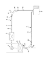
この発明に係る配管の制振構造が用いられる一例として、図1において、車両用空調装置の冷凍サイクル1が示されている。この冷凍サイクル1は、コンプレッサ2、コンデンサ3、膨張弁4、エバポレータ5が少なくとも配管接続されて構成されたもので、コンプレッサ2で圧縮されて高温高圧化した冷媒をコンデンサ3に送り、このコンデンサ3でかかる高温高圧の冷媒を放熱して凝縮した後、凝縮された冷媒を膨張弁4で膨張させ、さらにエバポレータ5で空調ダクト6内を流れる空気からの吸熱により冷媒を蒸発させて、コンプレッサ2に戻す作用をなす、それ自体は公知のものである。尚、冷媒の種類は、冷凍サイクル用冷媒、例えばR134a冷媒、CO2冷媒、その他の炭化水素系冷媒等が挙げられ、特に限定されない。また、コンプレッサ2、コンデンサ3、膨張弁4、エバポレータ5以外に、気相冷媒と液相冷媒とを分離する気液分離器や、高圧冷媒と低圧冷媒とを熱交換させる内部熱交換器等を有した構成であっても良い。
As an example in which the vibration damping structure for piping according to the present invention is used, a refrigeration cycle 1 of a vehicle air conditioner is shown in FIG. The refrigeration cycle 1 is configured by connecting a
そして、この実施形態では、コンデンサ3とコンプレッサ2及びコンプレッサ2とエバポレータ5とは、それぞれ配管7を用いて配管接続されたものとなっている。これらの配管7は、図2(b)に示されるように、第1の硬質パイプ8及び第2の硬質パイプ9と、フレキシブル部材10とを有して基本的に構成されている。
In this embodiment, the
このうち、第1の硬質パイプ8及び第2の硬質パイプ9は、例えば金属等の剛性の高い素材で形成されたものとなっているもので、配管のレイアウトが相対的に厳しいところに用いられている。フレキシブル部材10は、図4(b)に示されるように、例えばゴム等の可撓性を有する素材から構成された略円筒状のものである。
Among these, the first
そして、フレキシブル部材10は、第1の硬質パイプ8の長手方向に沿った一方側端部とは筒状のかしめ部材11を介して連結され、第2の硬質パイプの長手方向に沿った一方端側端部とは筒状のかしめ部材12を介して連結されていると共に、パイプ8、9の一方から他方へ(例えば、コンプレッサ2側の硬質パイプ9から硬質パイプ8へ)の振動の伝播を減衰すべく、図1では後述する制振部材14を外装した状態であるが、エンジン室の配管レイアウトに沿った角度Rで曲折された状態にて用いられる。
And the
制振部材14は、フレキシブル部材10の軸方向に沿った面に対し外周側に配置されているもので、発泡EPDM、ソリッドEPDM、発泡ゴム、発泡プラスチック等の相対的に比重の軽く、柔軟な素材が用いられる。そして、図2に示されるように、厚みが例えば3mmから5mmの制振部材14が単体でフレキシブル部材10の全周にわたって外装されるものであっても、図3に示されるように、厚みが例えば8mmの制振部材14、14が複数(この実施例では2つ)、フレキシブル部材10に外装されるものであっても良い。
The
図2の単体の制振部材14を用いる場合では、かしめ部材11、12が制振部材14のフレキシブル部材10に対してその軸方向へのずれを規制し、図3の2つの制振部材14、14を用いる場合では、かしめ部材11又は12と環状の締め付けバンド15とが制振部材14のフレキシブル部材10に対してその軸方向へのずれを規制したものとなっている。尚、単体の制振部材14を用いる場合において、図示しないが、制振部材14がフレキシブル部材10の全範囲を覆うものとせず、これに伴い、締め付けバンド15を用いて、かしめ部材11又は12と締め付けバンド15とで制振部材14のフレキシブル部材10に対してその軸方向へのずれを規制するものとしても良い。
When the single damping
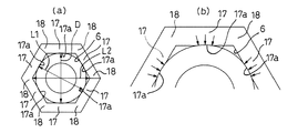
そして、制振部材14は、フレキシブル部材10に外装した際に、フレキシブル部材10の軸方向に沿った面と常時において接触する1以上の接触部分17と、複数の接触部分17の間又は1の接触部分17の両端の間に位置してフレキシブル部材10の軸方向に沿った面と接触しない離隔部分18とを有する構成のもので、この構成を採るべく、図4(a)においては、外形状が軸方向側から見て正六角形状をなすと共にフレキシブル部材10の軸方向に沿った側面と対峙する内側面で画成された内部空間Sも軸方向側から見て正六角形状をなしており、この内部空間Sの図4(a)で示される最小内径寸法L1はフレキシブル部材10の図4(b)で示される外径寸法Dよりも小さく、内部空間Sの図4(a)で示される最大内径寸法L2はフレキシブル部材10の図4(b)で示される外径寸法Dよりも大きくなるように設定されている。ここで、制振部材14は、6つの接触部分17と6つの離隔部分18とを有したものとなっている。
When the damping
これにより、制振部材14をフレキシブル部材10に外装した際に、制振部材14の離隔部分18が変形し、この離隔部分18の変形から元の状態に戻ろうとする力が、図5(b)に示されるように、この離隔部分18の両側に位置する接触部分17の面17aがフレキシブル部材10を押圧する力となる。よって、フレキシブル部材が振動するとフレキシブル部材10と制振部材14の接触部分17との接触部位に動摩擦が発生し、フレキシブル部材10の振動エネルギーが消費される。
Thereby, when the damping
すなわち、内部空間が軸方向から見て真円状で且つ当該内部空間の内径寸法がフレキシブル部材の外径寸法よりも小さな制振部材をフレキシブル部材に外装した場合には、内部空間の内径寸法及びフレキシブル部材の外径寸法について厳格に公差寸法管理をしないと、制振部材がその径方向外側に向けて過度に拡張されることにより制振部材のフレキシブル部材への押圧力が過大となって効果的な動摩擦が発生せず、制振効果が期待できないところ、本願に係る制振部材14ではこれらの不具合を解決している。
That is, when the damping member is sheathed on the flexible member with the inner space having a perfect circular shape when viewed from the axial direction and the inner diameter of the inner space being smaller than the outer diameter of the flexible member, If the tolerance dimension control is not strictly controlled for the outer diameter of the flexible member, the damping member is excessively expanded toward the outside in the radial direction, and the pressing force of the damping member on the flexible member is excessive. However, in the
そして、この内部空間Sの図4(a)で示される最小内径寸法L1の数値はフレキシブル部材10の図4(b)で示される外径寸法Dよりも小さければ良く、内部空間Sの図4(a)で示される最大内径寸法L2の数値はフレキシブル部材10の図4(b)で示される外径寸法Dよりも大きければ良いもので、図6に示されるように、制振部材14の内部空間Sの形状が変化することでこの寸法誤差を吸収することが可能であるので、制振部材14の最小内径寸法L1、最大内径寸法L2の寸法精度をあまり厳格に採る必要がない。
The numerical value of the minimum inner diameter dimension L1 shown in FIG. 4A of the internal space S only needs to be smaller than the outer diameter dimension D shown in FIG. 4B of the
次に、制振部材14のフレキシブル部材10への装着手順の一例について説明すると、制振部材14は、図7に示されるように、軸方向に沿って延びる破断線Bにより一枚の板状に展開することが可能となっているもので、第1の硬質パイプ8、第2の硬質パイプ9とかしめ部材11又は12を介して接続された状態のフレキシブル部材10に対して、制振部材14を展開した状態にして、フレキシブル部材10の径方向に沿った側から覆った後、制振部材14の破断線Bにより分けられた端面同士を接着剤等により接着することで装着する。尚、破断線Bは、制振部材14のうち離隔部分18の角の頂点にあたる部位を切れ目の位置とするのが好適であり、これにより切れ目に接着剤を塗布した際にフレキシブル部材10の外周面に接着剤が付着するのを防止することが可能である。
Next, an example of a procedure for mounting the
その一方で、制振部材14の接触部分17がフレキシブル部材10の軸方向に沿った側面を複数箇所において押圧することによる締め付けと振動の減衰との関係を確認すべく、制振部材14を有しない場合、制振部材14がフレキシブル部材10に対し、きつく締め付ける場合、及び制振部材14がフレキシブル部材10に対し、緩く締め付ける場合の3つの態様にて実験した。この実験は、図8(a)の矢印に示されるように、第2の硬質パイプ9に対し0から1000Hzまでの範囲で周波数が生ずるように振動を与え、第1の硬質パイプ8と第2の硬質パイプ9とでそれぞれで振動数を計測して比較し、第1の硬質パイプ8での振動の減衰量を認定するという方法でおこなった。尚、図8(a)では、フレキシブル部材10に制振部材14を装着した状態の構成のみが示されているがこれは便宜上のもので、フレキシブル部材10に制振部材14を装着しない構成についても同様の態様で実験がなされている。
On the other hand, in order to confirm the relationship between tightening and vibration attenuation due to the
この実験の結果、図8(b)に示されるように、制振部材14をフレキシブル部材10に対し相対的に緩く装着した構成では、制振部材14を装着しない構成に比べ、周波数帯が0ヘルツから1000ヘルツまでの全範囲で振動の減衰量が大きく、且つ制振部材14をフレキシブル部材10に対し相対的にきつく装着した構成に比べ、車両自体の振動、配管を流れる冷媒等の流体の振動乃至はかかる配管が締結されているポンプやコンプレッサから伝わる振動や脈動で生ずる振動の主な周波数帯たる200ヘルツから500ヘルツまでの範囲で、振動の減衰量が相対的に大きいことが認められた。
As a result of this experiment, as shown in FIG. 8B, in the configuration in which the damping
これに伴い、制振部材14をフレキシブル部材10に対し相対的に緩く装着するにあたり、制振部材14の接触部分17がフレキシブル部材10をどの程度の力で押圧するのが適当であるかを確認すべく、外径寸法が23mm、長手方向に沿った寸法が320mmのフレキシブル部材を備える配管7に、外径寸法が38mm〜40mm、内径寸法が22mm、厚みが7.5mm〜8mm、長手方向に沿った寸法が320mmの円筒状の制振部材を装着したまま、第1のパイプ部材8に対して第2のパイプ部材9を45度の角度で曲折させた場合と、90度の角度で曲折させた場合との2つのパターンで、且つ、上記制振部材をフレキシブル部材の軸方向に沿って引っ張り、かかる制振部材とフレキシブル部材との間で生ずる最大静止摩擦力を計測するかたちで実験を行った。尚、曲折される角度をこのように設定したのは、45度より小さい角度ではフレキシブル部材の振動減衰効果が得られ難く車両に組付けられる事例が少ないことと、90度よりも大きい角度ではフレキシブル部材の振動減衰効果が得られやすく制振部材の必要性が低くなるためである。
Accordingly, when attaching the damping
制振部材をその全周に装着したままフレキシブル部材を45度の角度で曲折した構成での実験の結果、図9の2点鎖線による枠に示されるように、200ヘルツから500ヘルツまでの周波数帯のいずれについても、最大静止摩擦力が35ニュートンから75ニュートンとなるように、制振部材がフレキシブル部材を押圧する場合に、相対的減衰量が大きくなった。特に、図9の1点鎖線による枠に示されるように、自動車で最も生じやすい周波数帯の300ヘルツの周波数では、50ニュートンから60ニュートンとなるように、制振部材の接触部分がフレキシブル部材を押圧する場合に、相対的に振動の減衰量が大きくなった。 As a result of an experiment in a configuration in which the flexible member is bent at an angle of 45 degrees with the damping member attached to the entire circumference, as shown in the frame by the two-dot chain line in FIG. 9, the frequency from 200 to 500 hertz In any of the bands, the relative damping amount increased when the damping member pressed the flexible member so that the maximum static frictional force was 35 Newtons to 75 Newtons. In particular, as shown in the frame by the one-dot chain line in FIG. 9, the contact portion of the damping member is made of a flexible member so that the frequency is from 50 Newtons to 60 Newtons at a frequency of 300 Hertz that is most likely to occur in an automobile. When pressing, the amount of vibration attenuation was relatively large.
また、制振部材をその全周に装着したままフレキシブル部材を90度の角度で曲折した構成での実験の結果でも、図10の2点鎖線による枠に示されるように、200ヘルツから500ヘルツまでの周波数帯のいずれについても、最大静止摩擦力が35ニュートンから75ニュートンとなるように、制振部材の接触部分がフレキシブル部材を押圧する場合に、相対的減衰量が大きくなった。特に、図10の1点鎖線による枠に示されるように、自動車で最も生じやすい周波数帯の300ヘルツの周波数では、50ニュートンから60ニュートンとなるように、制振部材の接触部分がフレキシブル部材を押圧する場合に、相対的に振動の減衰量が大きくなった。 Further, even in the result of the experiment in the configuration in which the flexible member is bent at an angle of 90 degrees with the vibration damping member mounted on the entire circumference, as shown in the frame by the two-dot chain line in FIG. In any of the frequency bands up to, when the contact portion of the damping member pressed the flexible member so that the maximum static frictional force was 35 to 75 Newton, the relative attenuation amount was increased. In particular, as shown in the frame by the one-dot chain line in FIG. 10, the contact portion of the vibration damping member is a flexible member so that the frequency is from 50 Newton to 60 Newton at a frequency of 300 Hertz that is most likely to occur in an automobile. When pressing, the amount of vibration attenuation was relatively large.
しかるに、制振部材14の最小内径寸法L1及び最大内径寸法L2の数値の設定は、図2に示される制振部材14がフレキシブル部材10に装着された際に、制振部材14の接触部分17がフレキシブル部材10を押圧して、制振部材14とフレキシブル部材10との間に最大静止摩擦力として35ニュートンから75ニュートン、より好適には50ニュートンから60ニュートンの数値が計測される力が生ずる構成とすることが求められる。
However, the numerical values of the minimum inner diameter dimension L1 and the maximum inner diameter dimension L2 of the
もっとも、制振部材14の構成は、図4(a)及び図7に示されるものに限定されず、制振部材14の内部空間Sにおける最小内径寸法L1がフレキシブル部材10の外径寸法Dよりも小さく最大内径寸法L2がフレキシブル部材10の外径寸法Dよりも大きく、これにより、制振部材14が接触部分17と離隔部分18とを有し、制振部材14がフレキシブル部材10に装着された際に、制振部材14の離隔部分18が変形して接触部分17がフレキシブル部材10を押圧し、これにより制振材14とフレキシブル部材10との間で最大静止摩擦力の計測値が35ニュートンから75ニュートン、より望ましくは50ニュートンから60ニュートンの数値が計測されれば良い。
However, the configuration of the damping
以下、制振部材14の変形例について、図11から図16を用いて説明する。但し、先の制振部材14と同様の構成については同一の符号を付してその説明を省略する。
Hereinafter, modified examples of the damping
図11に示される制振部材14は、外形状がその軸方向から見て正八角形状をなしていると共に、その内部空間Sも軸方向から見て正八角形状をなしているもので、この内部空間Sの最小内径寸法L1はフレキシブル部材10の外径寸法Dよりも小さく、当該内部空間Sの最大内径寸法L2はフレキシブル部材10の外径寸法Dよりも大きくなっている。これにより、制振部材14は、フレキシブル部材10と組み付けた際に、フレキシブル部材10の外周面と常時において接触する8つの接触部分17と、この接触部分17の間に位置してフレキシブル部材10の外周面と接触しない8つの離隔部分18とを有し、且つ離隔部分18の変形により接触部分17の面17aがフレキシブル部材10を相対的に緩く押圧するものとなっている。すなわち、制振部材14とフレキシブル部材10との間で最大静止摩擦力が35ニュートンから75ニュートン、より望ましくは50ニュートンから60ニュートンの計測値となっている。
The damping
図12に示される制振部材14は、外形状がその軸方向から見て真円状をなしていると共にその内部空間Sは軸方向から見て正六角形状をなしている。この制振部材14の内部空間Sの最小内径寸法L1はフレキシブル部材10の外径寸法Dよりも小さく、当該内部空間Sの最大内径寸法L2はフレキシブル部材10の外径寸法Dよりも大きくなっている。これにより、制振部材14は、フレキシブル部材10と組み付けた際に、フレキシブル部材10の外周面と常時において接触する6つの接触部分17と、接触部分17の間に位置してフレキシブル部材10の外周面と接触しない6つの離隔部分18とを有し、且つ離隔部分18の変形により接触部分17の面17aがフレキシブル部材10を相対的に緩く押圧するものとなっている。すなわち、制振部材14とフレキシブル部材10との間で最大静止摩擦力が35ニュートンから75ニュートン、より望ましくは50ニュートンから60ニュートンの計測値となっている。
The damping
図13に示される制振部材14は、外形状がその軸方向から見て真円部分とこの真円部分からその径方向に突出した突出部分とを組み合わせた不均衡な形状をなしていると共に、その内部空間Sも軸方向から見て真円部分とこの真円部分からその径方向に突出した突出部分とを組み合わせた不均衡な形状をなしているもので、バネとなる部分を有している。この制振部材14の内部空間Sの突出部分と真円部分の中心とを結ぶ最大内径寸法L2はフレキシブル部材10の外径寸法Dよりも大きく、当該内部空間Sの真円部分の内径寸法でもある最小内径寸法L1はフレキシブル部材10の外径寸法Dよりも小さくなっている。これにより、制振部材14は、フレキシブル部材10と組み付けた際に、フレキシブル部材10の外周面と常時において接触する1つの接触部分17と、この接触部分17の両端の間に位置してフレキシブル部材10の外周面と接触しない1つの離隔部分18とを有し、且つ離隔部分18の変形により接触部分17の面17aがフレキシブル部材10を相対的に緩く押圧するものとなっている。すなわち、制振部材14とフレキシブル部材10との間で最大静止摩擦力が35ニュートンから75ニュートン、より望ましくは50ニュートンから60ニュートンの計測値となっている。
The damping
図14に示される制振部材14は、外形状がその軸方向から見て真円状をなしていると共に内部空間Sは軸方向から見て真円部分とこの真円部分からその径方向に沿って放射状に突出した複数(この実施例では12)の突出部分とを組み合わせた形状をなしている。
この制振部材14の内部空間Sの突出部分と真円部分の中心を経て反対側の突出部分とを結ぶ最大内径寸法L2はフレキシブル部材10の外径寸法Dよりも大きく、当該内部空間Sの真円部分の内径寸法でもある最小内径寸法L1はフレキシブル部材10の外径寸法Dよりも小さくなっている。これにより、制振部材14は、フレキシブル部材10と組み付けた際に、フレキシブル部材10の外周面と常時において接触する12の接触部分17と、接触部分17の間に位置してフレキシブル部材10の外周面と接触しない12の離隔部分18とを有し、且つ離隔部分18の変形により接触部分17の面17aがフレキシブル部材10を相対的に緩く押圧するものとなっている。すなわち、制振部材14とフレキシブル部材10との間で最大静止摩擦力が35ニュートンから75ニュートン、より望ましくは50ニュートンから60ニュートンの計測値となっている。
The damping
The maximum inner diameter L2 connecting the protruding portion of the internal space S of the
図15に示される制振部材14は、外形状がその軸方向から見てフレキシブル部材10の円周方向に沿って複数の凹部と凸部(この実施例では8つの凹部と8つの凸部)とが繰り返し並ぶ形状を有すると共に、内部空間Sも軸方向から見て制振部材14の外形状と相似形としつつフレキシブル部材10の円周方向に沿って複数の凹部と凸部(この実施例では8つの凹部と8つの凸部)とが繰り返し並ぶ形状をなしている。この制振部材14の内部空間Sの凸部と当該内部空間Sの中心点を経て反対側の凸部とを結ぶ最大内径寸法L2はフレキシブル部材10の外径寸法Dよりも大きく、当該内部空間Sの凹部と当該内部空間Sの中心点を経て反対側の凹部とを結ぶ最小内径寸法L1はフレキシブル部材10の外径寸法Dよりも大きくなっている。これにより、制振部材14は、フレキシブル部材10と組み付けた際に、フレキシブル部材10の外周面と常時において接触する8つの接触部分17と、接触部分17の間に位置してフレキシブル部材10の外周面と接触しない18つの離隔部分18とを有し、且つ離隔部分18の変形により接触部分17の面17aがフレキシブル部材10を相対的に緩く押圧するものとなっている。すなわち、制振部材14とフレキシブル部材10との間で生ずる最大静止摩擦力が35ニュートンから75ニュートン、より望ましくは50ニュートンから60ニュートンの計測値となっている。
The damping
そして、図16に示される制振部材14は、外形状がその軸方向から見て半円部分と四角形部分とを組み合わせた、2つの角を有する不均衡な形状をなしていると共に、内部空間Sも軸方向から見て制振部材14の外形状と相似形としつつ半円部分と四角形部分とを組み合わせた、2つの角部を有する不均衡な形状をなしている。この制振部材14の内部空間Sの四角形部分の角と当該内部空間Sの中心点を経て半円部分側端とを結ぶ最大内径寸法L2はフレキシブル部材10の外径寸法Dよりも大きく、当該内部空間Sの半円部分の直径方向寸法でもある最小内径寸法L1はフレキシブル部材10の外径寸法Dよりも大きくなっている。これにより、制振部材14は、フレキシブル部材10と組み付けた際に、フレキシブル部材10の外周面と常時において接触する2つの接触部分17(接触部分17の1つは半円部分の縁線と同じ)、接触部分17の間に位置してフレキシブル部材10の外周面と接触しない2つの離隔部分18とを有し、且つ離隔部分18の変形により接触部分17の面17aがフレキシブル部材10を相対的に緩く押圧するものとなっている。すなわち、制振部材14とフレキシブル部材10との間で最大静止摩擦力が35ニュートンから75ニュートン、より望ましくは50ニュートンから60ニュートンの計測値となっている。
The damping
よって、これらの図11から図16に示される制振部材14によっても、図4(a)及び図7に示される制振部材14の図9、図10に示される実験結果と同様に、第2の硬質パイプ9から第1の硬質パイプ8にコンプレッサ2等が発生源の振動が伝播するのを、減衰させることが可能である。
Therefore, even with the
更に、制振部材14をフレキシブル部材10の外面に装着するための構造として、当該制振部材14の軸方向に沿って直線状に延びる破断線Bを示してきたが必ずしもこれに限定されず、図17に示されるように、制振部材14に対しその軸方向に沿って一方端から他方端まで螺旋状に延びる破断線Bが形成されたものとしても良い。これによれば、フレキシブル部材10に外装することで変形した制振部材14は元の状態に戻ろうとする力が生じ、この力により制振部材14がフレキシブル部材10に対し相対的に緩い押圧を行うことができるものとなる。従って、破断線Bが図17に示されるように螺旋状の場合には、図示しないが内部空間Sの形状は真円状であっても良い。
Furthermore, as a structure for mounting the damping
更にまた、制振部材14は、図示しないがフレキシブル部材10に対しその円周方向においてその全範囲を覆う形状でなくても良く、その軸方向から見て略C字形状であっても良い。そして、制振部材14は、例えば図12に示される部位の外周側に当該部位よりも硬質な素材で形成された円筒状の拘束層部位を有するものとしても良い。この場合には、例えば、制振部材14の内側部位は発泡EPDM、拘束層部位にはソリッドEPDMが用いられる。このような構成の制振部材14とすることにより、制振部材14はフレキシブル部材10の振動により生じた振動エネルギーの消費をより効果的に行うことができ、振動の減衰量も相対的に大きくなる。
Furthermore, although not shown, the damping
7 配管
8 第1の硬質パイプ(第1のパイプ部材)
9 第2の硬質パイプ(第2のパイプ部材)
10 フレキシブル部材
14 制振部材
17 接触部分
18 離隔部分
S 制振部材の内部空間
B 制振部材の破断線
L1 制振部材の内部空間の最小内径寸法
L2 制振部材の内部空間の最大内径寸法
7 Piping 8 First hard pipe (first pipe member)
9 Second hard pipe (second pipe member)
DESCRIPTION OF
Claims (7)
この制振部材は、前記フレキシブル部材と当該制振部材との間で生ずる最大静止摩擦力の数値が、35ニュートンから75ニュートン、より好ましくは50ニュートンから60ニュートンになるように、前記フレキシブル部材に対し相対的に緩く押圧することが可能に、前記フレキシブル部材に外装されていることを特徴とする配管制振構造。 A flexible member that is elastic and can be bent in any direction and allows fluid to pass through the inside thereof; a first pipe member connected to one end in the longitudinal direction of the flexible portion; and A pipe comprising at least a second pipe member connected to the other end in the longitudinal direction of the flexible member, and an internal space formed of an elastic body and open on both sides so as to be mounted on the outer peripheral side of the flexible member Consisting of damping members,
The vibration damping member is arranged on the flexible member so that the numerical value of the maximum static frictional force generated between the flexible member and the vibration damping member is 35 to 75 newtons, more preferably 50 to 60 newtons. A piping vibration damping structure characterized in that the flexible member is sheathed so that it can be pressed relatively loosely.
この制振部材は、前記内部空間の最小内径寸法が前記フレキシブル部材の外径寸法よりも小さく、前記内部空間の最大内径寸法が前記フレキシブル部材の外径寸法よりも大きくなるように設定されて、前記フレキシブル部材と組み付けた際に、前記フレキシブル部材の外周面と常時において接触する1以上の接触部分と、複数の接触部分の間又は1の接触部分の両端の間に位置して前記フレキシブル部材の外周面と常時において接触しない離隔部分とを有すると共に、
前記内部空間は、前記接触部分を前記フレキシブル部材に組み付けた際に前記離隔部分が変形し、この変形により生じた力を、前記接触部分が前記フレキシブル部材の外周面を内側に押し付ける力に変えることで、前記制振部材が前記フレキシブル部材を相対的に緩く押圧することが可能に画成されていることを特徴とする配管制振構造。 A flexible member that is elastic and can be bent in any direction and allows fluid to pass through the inside thereof; a first pipe member connected to one end in the longitudinal direction of the flexible portion; and A pipe comprising at least a second pipe member connected to the other end in the longitudinal direction of the flexible member, and an internal space formed of an elastic body and open on both sides so as to be mounted on the outer peripheral side of the flexible member Consisting of damping members,
The vibration damping member is set such that the minimum inner diameter dimension of the inner space is smaller than the outer diameter dimension of the flexible member, and the maximum inner diameter dimension of the inner space is larger than the outer diameter dimension of the flexible member, When assembled with the flexible member, the flexible member is positioned between one or more contact portions that are always in contact with the outer peripheral surface of the flexible member, and between the plurality of contact portions or both ends of the one contact portion. Having a separation portion that does not always contact the outer peripheral surface,
In the internal space, when the contact portion is assembled to the flexible member, the separation portion is deformed, and the force generated by the deformation is changed to a force by which the contact portion presses the outer peripheral surface of the flexible member inward. The piping damping structure is characterized in that the damping member is configured to be able to press the flexible member relatively loosely.
この制振部材について、その内部空間の最小内径寸法が前記フレキシブル部材の外径寸法よりも大きく、前記内部空間の最大内径寸法が前記フレキシブル部材の外径寸法よりも小さくなるように形成して、前記フレキシブル部材と組み付けた際に、前記フレキシブル部材の外周面と常時において接触する接触部分と、当該接触部分の間に位置して前記フレキシブル部材の外周面と接触しない離隔部分とを有するものとして、前記フレキシブル部材と前記制振部材とを組み付けて、前記制振部材の接触部分を前記フレキシブル部材に対し相対的に緩く押圧させることを特徴とする配管制振方法。 A flexible member that is elastic and can be bent in any direction and allows fluid to pass through the inside, a first pipe member connected to one end in the longitudinal direction of the flexible member, and A pipe consisting of at least a second pipe member connected to the other end in the longitudinal direction of the flexible member, and a damping member formed of an elastic body and disposed on the outer peripheral side of the flexible member are used.
About this vibration damping member, the minimum inner diameter dimension of the inner space is larger than the outer diameter dimension of the flexible member, and the maximum inner diameter dimension of the inner space is smaller than the outer diameter dimension of the flexible member, When assembled with the flexible member, it has a contact portion that is always in contact with the outer peripheral surface of the flexible member, and a separation portion that is located between the contact portions and does not contact the outer peripheral surface of the flexible member, A piping vibration damping method comprising assembling the flexible member and the vibration damping member and pressing a contact portion of the vibration damping member relatively loosely against the flexible member.
前記制振部材に前記フレキシブル部材を通す工程と、前記かしめ部材に前記フレキシブル部材と前記第1又は第2のパイプ部材を挿入してかしめる工程とを有することを特徴とする請求項5に記載の配管制振方法。 A caulking member into which the flexible member can be inserted and the first or second pipe member can be inserted is further used.
6. The method according to claim 5, further comprising: passing the flexible member through the damping member; and inserting and caulking the flexible member and the first or second pipe member into the caulking member. Piping vibration control method.
前記フレキシブル部材に前記制振部材を巻き付ける工程を有することを特徴とする請求項6に記載の配管制振方法。
The damping member has a cut extending from one end in the axial direction of the damping member toward the other end, and is configured to develop so that the cut becomes an end face.
The pipe damping method according to claim 6, further comprising a step of winding the damping member around the flexible member.
Priority Applications (1)
| Application Number | Priority Date | Filing Date | Title |
|---|---|---|---|
| JP2008133625A JP2009281482A (en) | 2008-05-21 | 2008-05-21 | Pipe vibration damping structure and pipe vibration damping method |
Applications Claiming Priority (1)
| Application Number | Priority Date | Filing Date | Title |
|---|---|---|---|
| JP2008133625A JP2009281482A (en) | 2008-05-21 | 2008-05-21 | Pipe vibration damping structure and pipe vibration damping method |
Publications (1)
| Publication Number | Publication Date |
|---|---|
| JP2009281482A true JP2009281482A (en) | 2009-12-03 |
Family
ID=41452150
Family Applications (1)
| Application Number | Title | Priority Date | Filing Date |
|---|---|---|---|
| JP2008133625A Pending JP2009281482A (en) | 2008-05-21 | 2008-05-21 | Pipe vibration damping structure and pipe vibration damping method |
Country Status (1)
| Country | Link |
|---|---|
| JP (1) | JP2009281482A (en) |
Cited By (5)
| Publication number | Priority date | Publication date | Assignee | Title |
|---|---|---|---|---|
| CN102312905A (en) * | 2010-07-07 | 2012-01-11 | 南通瑞和船舶配件有限公司 | Assembly method for external reinforcing ring type wound gasket |
| JP2016160829A (en) * | 2015-03-02 | 2016-09-05 | 株式会社デンソー | Vibration suppressing device and refrigeration cycle device including the same |
| KR20190120488A (en) * | 2018-04-16 | 2019-10-24 | 한온시스템 주식회사 | Pipe structure for vibration damping |
| CN113187849A (en) * | 2021-04-23 | 2021-07-30 | 重庆锐锦科技有限公司 | Road construction buried pipeline protection device easy to maintain |
| JP2021113522A (en) * | 2020-01-17 | 2021-08-05 | いすゞ自動車株式会社 | Reinforcing structure |
Citations (2)
| Publication number | Priority date | Publication date | Assignee | Title |
|---|---|---|---|---|
| JP2001032884A (en) * | 1999-07-21 | 2001-02-06 | Tokyo Gas Co Ltd | Flexible pipe with vibration restraining function |
| JP2003307294A (en) * | 2002-04-16 | 2003-10-31 | Kinugawa Rubber Ind Co Ltd | Vibration prevention tool for pipe |
-
2008
- 2008-05-21 JP JP2008133625A patent/JP2009281482A/en active Pending
Patent Citations (2)
| Publication number | Priority date | Publication date | Assignee | Title |
|---|---|---|---|---|
| JP2001032884A (en) * | 1999-07-21 | 2001-02-06 | Tokyo Gas Co Ltd | Flexible pipe with vibration restraining function |
| JP2003307294A (en) * | 2002-04-16 | 2003-10-31 | Kinugawa Rubber Ind Co Ltd | Vibration prevention tool for pipe |
Cited By (6)
| Publication number | Priority date | Publication date | Assignee | Title |
|---|---|---|---|---|
| CN102312905A (en) * | 2010-07-07 | 2012-01-11 | 南通瑞和船舶配件有限公司 | Assembly method for external reinforcing ring type wound gasket |
| JP2016160829A (en) * | 2015-03-02 | 2016-09-05 | 株式会社デンソー | Vibration suppressing device and refrigeration cycle device including the same |
| KR20190120488A (en) * | 2018-04-16 | 2019-10-24 | 한온시스템 주식회사 | Pipe structure for vibration damping |
| KR102497671B1 (en) * | 2018-04-16 | 2023-02-10 | 한온시스템 주식회사 | Pipe structure for vibration damping |
| JP2021113522A (en) * | 2020-01-17 | 2021-08-05 | いすゞ自動車株式会社 | Reinforcing structure |
| CN113187849A (en) * | 2021-04-23 | 2021-07-30 | 重庆锐锦科技有限公司 | Road construction buried pipeline protection device easy to maintain |
Similar Documents
| Publication | Publication Date | Title |
|---|---|---|
| JP2009281482A (en) | Pipe vibration damping structure and pipe vibration damping method | |
| JP5556624B2 (en) | Piping joint | |
| JP4529873B2 (en) | Air conditioning unit | |
| JP2013513767A (en) | Tube with improved connection suitable for air conditioning system | |
| KR101664070B1 (en) | Pipe fixing unit for vehicle | |
| JP2000337572A (en) | Refrigerant duct for air-conditioner | |
| JPH044393A (en) | Vibration control element of piping, piping with vibration control element, and pressure transmitting apparatus with vibration control element | |
| KR20070081239A (en) | Clip structure for fixing refrigerant pipe | |
| JP6406065B2 (en) | Vibration suppression apparatus and refrigeration cycle apparatus including the same | |
| JP5496131B2 (en) | Piping damping structure and refrigeration cycle apparatus equipped with the piping damping structure | |
| JP7135601B2 (en) | Joint | |
| JP2008089238A (en) | Air conditioner for vehicle | |
| JPH11182980A (en) | Refrigerant piping | |
| JP4211134B2 (en) | Piping fixing structure | |
| KR200436382Y1 (en) | vibration-proof apparatus for an air conditioner piping for a vehicle | |
| JP2009197919A (en) | Method of manufacturing piping joint | |
| WO2010142614A9 (en) | Integrated hydraulic damping device | |
| JP4144124B2 (en) | Heat exchanger | |
| JP2008002629A (en) | Liquid-filled vibration damper | |
| JP2009085373A (en) | Piping joint structure and refrigerating cycle unit for vehicle | |
| KR20200003952A (en) | Structure for vibration isolation in air conditioner compressor of vehicle | |
| KR102246426B1 (en) | Protector for air conditioning hose of vehicle | |
| CN112780864A (en) | Vibration reduction bent pipe, compressor and air conditioning system | |
| JP6567062B2 (en) | Air conditioner outdoor unit | |
| JPH01181046A (en) | Pressure reducing device for freezing cycle of air conditioner |
Legal Events
| Date | Code | Title | Description |
|---|---|---|---|
| A621 | Written request for application examination |
Free format text: JAPANESE INTERMEDIATE CODE: A621 Effective date: 20110509 |
|
| A977 | Report on retrieval |
Free format text: JAPANESE INTERMEDIATE CODE: A971007 Effective date: 20120312 |
|
| A131 | Notification of reasons for refusal |
Free format text: JAPANESE INTERMEDIATE CODE: A131 Effective date: 20120709 |
|
| A521 | Written amendment |
Effective date: 20120904 Free format text: JAPANESE INTERMEDIATE CODE: A523 |
|
| A131 | Notification of reasons for refusal |
Free format text: JAPANESE INTERMEDIATE CODE: A131 Effective date: 20130128 |
|
| A02 | Decision of refusal |
Free format text: JAPANESE INTERMEDIATE CODE: A02 Effective date: 20130527 |