JP2009274663A - Vehicle energy absorbing structure - Google Patents
Vehicle energy absorbing structure Download PDFInfo
- Publication number
- JP2009274663A JP2009274663A JP2008129742A JP2008129742A JP2009274663A JP 2009274663 A JP2009274663 A JP 2009274663A JP 2008129742 A JP2008129742 A JP 2008129742A JP 2008129742 A JP2008129742 A JP 2008129742A JP 2009274663 A JP2009274663 A JP 2009274663A
- Authority
- JP
- Japan
- Prior art keywords
- vehicle
- region
- width direction
- pair
- energy absorption
- Prior art date
- Legal status (The legal status is an assumption and is not a legal conclusion. Google has not performed a legal analysis and makes no representation as to the accuracy of the status listed.)
- Pending
Links
Images


Abstract
Description
本発明は、車両エネルギ吸収構造に係り、特にエネルギ吸収部材を備えた車両エネルギ吸収構造に関する。 The present invention relates to a vehicle energy absorption structure, and more particularly to a vehicle energy absorption structure including an energy absorption member.
従来、この種の車両エネルギ吸収構造としては、次のものが知られている(例えば、特許文献1参照)。すなわち、特許文献1には、エネルギ吸収部材として円筒状CFRPを備えた例が開示されている。
しかしながら、特許文献1に記載の例では、円筒状CFRPが円筒状に形成されている。このため、円筒状CFRPに衝撃荷重が作用し、この衝撃荷重を円筒状CFRPが破壊されることで吸収させる際に、円筒状CFRPの内部に粉砕くずが溜まって詰まる虞がある。そして、この場合には、内部に詰まった粉砕くずによって円筒状CFRPの衝撃吸収性能が損なわれる虞がある。 However, in the example described in Patent Document 1, the cylindrical CFRP is formed in a cylindrical shape. For this reason, an impact load acts on the cylindrical CFRP, and when the impact load is absorbed by the destruction of the cylindrical CFRP, there is a possibility that crushing waste accumulates inside the cylindrical CFRP and becomes clogged. In this case, there is a possibility that the impact absorbing performance of the cylindrical CFRP may be impaired by the crushing waste clogged inside.
これを解決する手段としては、例えば、エネルギ吸収部材を車両前後方向視にて開断面状に形成することが考えられる。ところが、一般的に、エネルギ吸収部材が車両前後方向視にて開断面状に形成された場合には、閉断面状に形成された場合に比して、エネルギ吸収部材の耐力が減少する傾向にある。 As a means for solving this, for example, it is conceivable to form the energy absorbing member in an open cross-sectional shape when viewed in the vehicle front-rear direction. However, in general, when the energy absorbing member is formed in an open cross-sectional shape when viewed in the vehicle front-rear direction, the proof stress of the energy absorbing member tends to decrease compared to the case where it is formed in a closed cross-sectional shape. is there.
このため、エネルギ吸収部材が車両前後方向視にて開断面状に形成された場合、車両前後方向に対して角度のある方向からエネルギ吸収部材に衝撃荷重が作用したときに曲げモーメントが最大となるエネルギ吸収部材の根元部(つまり、エネルギ吸収部材における車両骨格部材との結合部)に折れが生じることを抑制するために、この部分の耐力を十分に確保する必要がある。 For this reason, when the energy absorbing member is formed in an open cross-sectional shape when viewed in the vehicle longitudinal direction, the bending moment is maximized when an impact load is applied to the energy absorbing member from a direction at an angle with respect to the vehicle longitudinal direction. In order to suppress the occurrence of breakage in the root portion of the energy absorbing member (that is, the joint portion of the energy absorbing member with the vehicle skeleton member), it is necessary to sufficiently ensure the proof strength of this portion.
このエネルギ吸収部材の根元部の耐力を十分に確保する対策としては、例えば、根元部の板厚を増加したり、根元部を部分的に閉断面状に形成したりすることも考えられる。ところが、この場合には、エネルギ吸収部材の質量が増加する。 As measures for sufficiently securing the proof strength of the root portion of the energy absorbing member, for example, increasing the plate thickness of the root portion or partially forming the root portion in a closed cross-sectional shape may be considered. However, in this case, the mass of the energy absorbing member increases.
本発明は、上記課題に鑑みてなされたものであって、エネルギ吸収部材の質量を増加させずに、エネルギ吸収部材の根元部の折れを抑制でき、軽量で高効率なエネルギ吸収部材によりエネルギ吸収させることができる車両エネルギ吸収構造を提供することを目的とする。 The present invention has been made in view of the above-described problems, and can suppress the bending of the root portion of the energy absorbing member without increasing the mass of the energy absorbing member, and can absorb energy by a light and highly efficient energy absorbing member. It is an object of the present invention to provide a vehicle energy absorption structure that can be made to operate.
前記課題を解決するために、請求項1に記載の車両エネルギ吸収構造は、車両幅方向に延在された荷重入力部材と、それぞれ車両前後方向に延在されて、前記荷重入力部材の車両幅方向中央部に対する車両幅方向両側で且つ車両前後方向一方側に配置された一対の車両骨格部材と、それぞれ車両前後方向における前記荷重入力部材と前記車両骨格部材との間に設けられて、車両前後方向一方側が前記車両骨格部材に結合され、車両前後方向他方側が前記荷重入力部材に結合されると共に、車両前後方向視にて開断面状に形成され、且つ、車両前後方向視における一対の自由端のうち少なくとも一方が、前記開断面の図心に対する車両幅方向外側の領域に配置された一対のエネルギ吸収部材と、を備えている。 In order to solve the above-mentioned problem, the vehicle energy absorption structure according to claim 1 includes a load input member extending in the vehicle width direction and a vehicle width of the load input member extending in the vehicle longitudinal direction. A pair of vehicle skeleton members disposed on both sides in the vehicle width direction with respect to the center in the direction and on one side in the vehicle longitudinal direction, and provided between the load input member and the vehicle skeleton member in the vehicle longitudinal direction, respectively. One side in the direction is coupled to the vehicle skeleton member, the other side in the vehicle front-rear direction is coupled to the load input member, and is formed in an open cross-sectional shape when viewed from the vehicle front-rear direction. At least one of them includes a pair of energy absorbing members disposed in a region outside the centroid of the open section in the vehicle width direction.
請求項1に記載の車両エネルギ吸収構造では、車両前後方向における荷重入力部材と車両骨格部材との間にエネルギ吸収部材が設けられている。そして、例えば、荷重入力部材に対して車両前後方向一方側へ相対移動する衝突体が車両前後方向他方側から荷重入力部材へ衝突し、荷重入力部材に車両前後方向一方側へ衝撃荷重が入力されると、この衝撃荷重がエネルギ吸収部材に伝達され、このエネルギ吸収部材が破壊されることで衝撃荷重のエネルギが吸収される。 In the vehicle energy absorption structure according to the first aspect, the energy absorption member is provided between the load input member and the vehicle skeleton member in the vehicle front-rear direction. For example, a colliding body that moves relative to the load input member in one side in the vehicle front-rear direction collides with the load input member from the other side in the vehicle front-rear direction, and an impact load is input to the load input member in one side in the vehicle front-rear direction. Then, the impact load is transmitted to the energy absorbing member, and the energy of the impact load is absorbed by breaking the energy absorbing member.
ここで、請求項1に記載の車両エネルギ吸収構造では、エネルギ吸収部材が車両前後方向視にて開断面状に形成されている。従って、エネルギ吸収部材に衝撃荷重が作用し、この衝撃荷重をエネルギ吸収部材が破壊されることで吸収させる際に、エネルギ吸収部材の内部に粉砕くずが溜まって詰まることを抑制することができる。これにより、エネルギ吸収部材の衝撃吸収性能を確保することができる。 Here, in the vehicle energy absorption structure according to the first aspect, the energy absorption member is formed in an open cross-sectional shape as viewed in the vehicle front-rear direction. Therefore, when an impact load is applied to the energy absorbing member and this impact load is absorbed by breaking the energy absorbing member, it is possible to suppress crushing dust from accumulating inside the energy absorbing member. Thereby, the impact absorption performance of the energy absorbing member can be ensured.
ところで、車両の衝突形態には、例えば、衝突体が荷重入力部材に垂直に衝突する場合や、衝突体が荷重入力部材に車両前後方向に対して車両幅方向外側に角度のある方向から斜めに衝突する場合等がある。そして、例えば、衝突体が荷重入力部材に車両前後方向に対して車両幅方向外側に角度のある方向から斜めに衝突する場合には、曲げモーメントが最大となるエネルギ吸収部材の根元部(エネルギ吸収部材における車両骨格部材との結合部)のうち車両幅方向内側の部分に最大圧縮応力が発生する。 By the way, in the collision mode of the vehicle, for example, when the colliding body collides perpendicularly with the load input member, or when the colliding body is oblique to the load input member with respect to the vehicle front-rear direction from the direction having an angle outward in the vehicle width direction. There may be a collision. For example, when the colliding body obliquely collides with the load input member from a direction with an angle outward in the vehicle width direction with respect to the vehicle front-rear direction, the base portion of the energy absorbing member (energy absorption) that maximizes the bending moment. The maximum compressive stress is generated in the inner part of the member in the vehicle width direction among the connecting part of the member to the vehicle skeleton member).
この点、請求項1に記載の車両エネルギ吸収構造では、エネルギ吸収部材の車両前後方向視における一対の自由端のうち少なくとも一方が、開断面の図心に対する車両幅方向外側の領域に配置されており、すなわち換言すれば、上述の曲げモーメントが最大となるエネルギ吸収部材の根元部のうち最大圧縮応力が発生する車両幅方向内側の部分以外の部分に配置されている。従って、例えば、断面崩れに対する耐力の小さい一対の自由端の両方がエネルギ吸収部材の根元部のうち最大圧縮応力が発生する車両幅方向内側の部分に配置された構成に比して、エネルギ吸収部材の根元部に折れが生じることを抑制することができる。 In this regard, in the vehicle energy absorbing structure according to claim 1, at least one of the pair of free ends of the energy absorbing member as viewed in the vehicle front-rear direction is disposed in a region outside the vehicle width direction with respect to the centroid of the open section. In other words, in other words, it is disposed in a portion other than the portion on the inner side in the vehicle width direction where the maximum compressive stress is generated in the root portion of the energy absorbing member where the bending moment is maximized. Therefore, for example, compared to a configuration in which both of the pair of free ends having a low yield strength against cross-sectional deformation are arranged in the vehicle width direction inner side portion where the maximum compressive stress is generated in the root portion of the energy absorbing member, the energy absorbing member It is possible to suppress the occurrence of folds at the root portion.
しかも、請求項1に記載の車両エネルギ吸収構造では、上述のように、車両前後方向視にて開断面状に形成されたエネルギ吸収部材の一対の自由端の位置を最適に設定しただけであり、根元部の板厚を増加したり根元部を部分的に閉断面状に形成したりしていないので、エネルギ吸収部材の質量の増加も防止できる。 Moreover, in the vehicle energy absorption structure according to claim 1, as described above, only the positions of the pair of free ends of the energy absorption member formed in an open cross-sectional shape when viewed in the vehicle longitudinal direction are set optimally. Further, since the thickness of the base portion is not increased or the base portion is not partially formed in a closed cross section, an increase in the mass of the energy absorbing member can be prevented.
このように、請求項1に記載の車両エネルギ吸収構造によれば、エネルギ吸収部材の質量を増加させずに、エネルギ吸収部材の根元部の折れを抑制でき、軽量で高効率なエネルギ吸収部材によりエネルギ吸収させることができる。 As described above, according to the vehicle energy absorption structure of the first aspect, the bending of the root portion of the energy absorption member can be suppressed without increasing the mass of the energy absorption member, and the energy absorption member is lightweight and highly efficient. Energy can be absorbed.
請求項2に記載の車両エネルギ吸収構造は、請求項1に記載の車両エネルギ吸収構造において、一対の自由端が開断面の図心に対する車両幅方向内側且つ車両上下方向下側の領域以外の領域に配置されている、構成である。
The vehicle energy absorption structure according to
例えば、荷重入力部材の位置が衝突体に対して相対的に低い等により、車両前後方向に対して車両幅方向外側に角度があるだけでなく車両上下方向上側にも角度がある方向から衝突体が荷重入力部材に斜めに衝突する場合がある。この場合には、曲げモーメントが最大となるエネルギ吸収部材の根元部のうち車両幅方向内側且つ車両上下方向下側の部分に最大圧縮応力が発生する。 For example, when the position of the load input member is relatively low with respect to the collision body, the collision body not only has an angle on the outer side in the vehicle width direction with respect to the vehicle longitudinal direction but also has an angle on the upper side in the vehicle vertical direction. May collide diagonally with the load input member. In this case, the maximum compressive stress is generated in the vehicle width direction inner side and the vehicle vertical direction lower side of the root part of the energy absorbing member where the bending moment is maximized.
この点、請求項2に記載の車両エネルギ吸収構造では、エネルギ吸収部材の車両前後方向視における一対の自由端が、開断面の図心に対する車両幅方向内側且つ車両上下方向下側の領域以外の領域、すなわち換言すれば、上述の曲げモーメントが最大となるエネルギ吸収部材の根元部のうち最大圧縮応力が発生する車両幅方向内側且つ車両上下方向下側の部分以外の部分に配置されている。従って、例えば、断面崩れに対する耐力の小さい一対の自由端の少なくとも一方がエネルギ吸収部材の根元部のうち最大圧縮応力が発生する車両幅方向内側且つ車両上下方向下側の部分に配置された構成に比して、エネルギ吸収部材の根元部に折れが生じることを抑制することができる。
In this regard, in the vehicle energy absorption structure according to
請求項3に記載の車両エネルギ吸収構造は、請求項1に記載の車両エネルギ吸収構造において、前記一対の自由端が前記開断面の図心に対する車両幅方向内側且つ車両上下方向上側の領域以外の領域に配置されている、構成である。 The vehicle energy absorption structure according to claim 3 is the vehicle energy absorption structure according to claim 1, wherein the pair of free ends is other than the region on the vehicle width direction inner side and the vehicle vertical direction upper side with respect to the centroid of the open section. This is a configuration arranged in the area.
例えば、荷重入力部材の位置が衝突体に対して相対的に高い等により、車両前後方向に対して車両幅方向外側に角度があるだけでなく車両上下方向下側にも角度がある方向から衝突体が荷重入力部材に斜めに衝突する場合がある。この場合には、曲げモーメントが最大となるエネルギ吸収部材の根元部のうち車両幅方向内側且つ車両上下方向上側の部分、すなわち、開断面の図心に対する車両幅方向内側且つ車両上下方向上側の領域に最大圧縮応力が発生する。 For example, when the position of the load input member is relatively high with respect to the collision body, the vehicle collides from not only the angle in the vehicle width direction outside the vehicle longitudinal direction but also the angle in the vehicle vertical direction lower side. The body may collide with the load input member at an angle. In this case, in the root portion of the energy absorbing member where the bending moment is maximized, the portion on the vehicle width direction inner side and the vehicle vertical direction upper side, that is, the vehicle width direction inner side and the vehicle vertical direction upper side in the centroid of the open section Maximum compressive stress is generated.
この点、請求項3に記載の車両エネルギ吸収構造では、エネルギ吸収部材の車両前後方向視における一対の自由端が、開断面の図心に対する車両幅方向内側且つ車両上下方向上側の領域以外の領域、すなわち換言すれば、上述の曲げモーメントが最大となるエネルギ吸収部材の根元部のうち最大圧縮応力が発生する車両幅方向内側且つ車両上下方向上側の部分以外の部分に配置されている。従って、例えば、断面崩れに対する耐力の小さい一対の自由端の少なくとも一方がエネルギ吸収部材の根元部のうち最大圧縮応力が発生する車両幅方向内側且つ車両上下方向上側の部分に配置された構成に比して、エネルギ吸収部材の根元部に折れが生じることを抑制することができる。 In this respect, in the vehicle energy absorbing structure according to claim 3, the pair of free ends of the energy absorbing member in the vehicle front-rear direction view is a region other than the region on the vehicle width direction inner side and the vehicle vertical direction upper side with respect to the centroid of the open section That is, in other words, the energy absorbing member having the maximum bending moment is disposed at a portion other than the portion on the vehicle width direction inner side and the vehicle vertical direction upper side where the maximum compressive stress is generated. Therefore, for example, at least one of a pair of free ends having a low yield strength against cross-sectional deformation is compared with a configuration in which the maximum compressive stress is generated in the root portion of the energy absorbing member and the vehicle width direction inner side and the vehicle vertical direction upper side part. And it can suppress that a fold arises in the root part of an energy absorption member.
請求項4に記載の車両エネルギ吸収構造は、請求項1〜請求項3のいずれか一項に記載の車両エネルギ吸収構造において、前記一対の自由端の一方が前記開断面の図心に対する車両幅方向外側且つ車両上下方向上側の領域に配置され、前記一対の自由端の他方が前記開断面の図心に対する車両幅方向外側且つ車両上下方向下側の領域に配置されている、構成である。 The vehicle energy absorption structure according to claim 4 is the vehicle energy absorption structure according to any one of claims 1 to 3, wherein one of the pair of free ends is a vehicle width with respect to the centroid of the open section. This is a configuration in which the other of the pair of free ends is arranged in a vehicle width direction outside and a vehicle vertical direction lower side with respect to the centroid of the open section.
請求項4に記載の車両エネルギ吸収構造によれば、一対の自由端が、開断面の図心に対する車両幅方向外側且つ車両上下方向上側の領域と、車両幅方向外側且つ車両上下方向下側の領域とに配置されており、すなわち換言すれば、エネルギ吸収部材の根元部のうち圧縮応力の小さい車両幅方向外側の部分に配置されている。従って、例えば、一対の自由端の一方のみがエネルギ吸収部材の根元部のうち圧縮応力の小さい車両幅方向外側の部分に配置された構成(又は、例えば、一対の自由端がエネルギ吸収部材の根元部のうち圧縮応力の大きい車両幅方向内側の部分に配置された構成)に比して、エネルギ吸収部材の根元部に折れが生じることを効果的に抑制することができる。 According to the vehicle energy absorption structure of the fourth aspect, the pair of free ends are located on the vehicle width direction outer side and the vehicle vertical direction upper side with respect to the centroid of the open section, and on the vehicle width direction outer side and the vehicle vertical direction lower side. In other words, in other words, it is disposed in the vehicle width direction outside portion where the compressive stress is small in the root portion of the energy absorbing member. Therefore, for example, a configuration in which only one of the pair of free ends is disposed in the vehicle width direction outer side where the compressive stress is small in the root portion of the energy absorbing member (or, for example, the pair of free ends is the root of the energy absorbing member. It is possible to effectively prevent the root portion of the energy absorbing member from being bent as compared with a configuration in which the portion of the energy absorbing member is disposed in the portion in the vehicle width direction having a large compressive stress.
請求項5に記載の車両エネルギ吸収構造は、請求項4に記載の車両エネルギ吸収構造において、前記エネルギ吸収部材が、車両上下方向における前記一対の自由端の間で前記開断面の図心に対する車両幅方向外側の領域に配置された少なくとも一つの山部と、車両上下方向における前記自由端の一方と前記山部との間で前記開断面の図心に対する車両幅方向内側且つ車両上下方向上側の領域に配置された第一谷部と、車両上下方向における前記自由端の他方と前記山部との間で前記開断面の図心に対する車両幅方向内側且つ車両上下方向下側の領域に配置された第二谷部とを有する、構成である。 The vehicle energy absorbing structure according to claim 5 is the vehicle energy absorbing structure according to claim 4, wherein the energy absorbing member is a vehicle with respect to the centroid of the open section between the pair of free ends in the vehicle vertical direction. Between at least one peak portion disposed in the outer region in the width direction and one of the free ends in the vehicle vertical direction and the peak portion, the vehicle width direction inner side and the vehicle vertical direction upper side with respect to the centroid of the open section. Between the first valley portion disposed in the region, the other free end in the vehicle vertical direction and the mountain portion, the vehicle is disposed in the vehicle width direction inner side and the vehicle vertical direction lower side with respect to the centroid of the open section. And having a second trough.
請求項5に記載の車両エネルギ吸収構造によれば、エネルギ吸収部材には少なくとも一つの山部と第一谷部と第二谷部とが形成されている。従って、これら山部と第一谷部と第二谷部とによってエネルギ吸収部材の剛性が向上されるので、これにより、エネルギ吸収部材の根元部に折れが生じることをより一層効果的に抑制することができる。 According to the vehicle energy absorption structure of the fifth aspect, at least one peak portion, the first valley portion, and the second valley portion are formed in the energy absorption member. Therefore, since the rigidity of the energy absorbing member is improved by the peak portion, the first valley portion, and the second valley portion, it is possible to more effectively suppress the bending of the root portion of the energy absorbing member. be able to.
特に、第一谷部と第二谷部とは、開断面の図心に対する車両幅方向内側且つ車両上下方向上側の領域と車両幅方向内側且つ車両上下方向下側の領域、すなわち換言すれば、エネルギ吸収部材の根元部のうち圧縮応力の大きい車両幅方向内側の部分に配置されている。従って、この第一谷部と第二谷部によってエネルギ吸収部材の根元部のうち車両幅方向内側の部分の耐力を確保することができる。 In particular, the first valley portion and the second valley portion are the vehicle width direction inner side and the vehicle vertical direction upper side region and the vehicle width direction inner side and the vehicle vertical direction lower side region with respect to the centroid of the open section, in other words, It arrange | positions in the vehicle width direction inside part with a big compressive stress among the root parts of an energy absorption member. Therefore, the proof stress of the inner part in the vehicle width direction of the root part of the energy absorbing member can be ensured by the first valley part and the second valley part.
以上詳述したように、本発明によれば、エネルギ吸収部材の質量を増加させずに、エネルギ吸収部材の根元部の折れを抑制でき、軽量で高効率なエネルギ吸収部材によりエネルギ吸収させることができる。 As described above in detail, according to the present invention, it is possible to suppress the bending of the root portion of the energy absorbing member without increasing the mass of the energy absorbing member, and to absorb energy by the light energy efficient member. it can.
[第一実施形態]
はじめに、本発明の第一実施形態について説明する。
[First embodiment]
First, a first embodiment of the present invention will be described.
図1には、本発明の第一実施形態に係る車両エネルギ吸収構造10が斜視図にて示されている。なお、これらの図及び以下に説明する各図において示される矢印UP、矢印FR、矢印OUTは、車両上下方向上側、車両前後方向前側、車両幅方向外側をそれぞれ示している。
FIG. 1 is a perspective view of a vehicle
図1に示されるように、本発明の第一実施形態に係る車両エネルギ吸収構造10は、車両の前部に適用されており、荷重入力部材としてのバンパリインフォースメント12と、一対の車両骨格部材としてのサイドメンバ14(フロントサイドメンバ)と、エネルギ吸収部材としてのクラッシュボックス16とを主要な構成として備えている。
As shown in FIG. 1, a vehicle
バンパリインフォースメント12は、図示しないフロントバンパカバーを支持するためのものであり、車両幅方向に延在されている。サイドメンバ14は、それぞれ車両前後方向に延在されて、バンパリインフォースメント12の車両幅方向中央部に対する車両幅方向両側で且つ車両前後方向後側に配置されている。
The
クラッシュボックス16は、それぞれ車両前後方向におけるバンパリインフォースメント12とサイドメンバ14との間に設けられており、その車両前後方向後側は、サイドメンバ14に結合され、その車両前後方向前側は、バンパリインフォースメント12に結合されている。このクラッシュボックス16は、例えば、CFRP製とされており、車両前後方向に作用する衝撃荷重のエネルギを吸収可能な構成とされている。
The
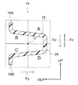
ここで、図2には、図1の2−2線断面によってクラッシュボックス16の断面が詳細に示されている。この図に示されるように、クラッシュボックス16は、車両前後方向視にて、所謂、波形状を成しており、車両前後方向視における一対の自由端16A,16Bを有する車両前後方向視にて開断面状に形成されている。
Here, in FIG. 2, the cross section of the
すなわち、一方の自由端16Aは、開断面の図心Oに対する車両幅方向外側且つ車両上下方向上側の領域(以下、領域Bという)に配置されており、他方の自由端16Bは、開断面の図心Oに対する車両幅方向外側且つ車両上下方向下側の領域(以下、領域Cという)に配置されている。
That is, one
また、車両上下方向における一対の自由端16A,16Bの間には、領域B及び領域Cを跨ぐように山部18が配置されている。一方、車両上下方向における一方の自由端16Aと山部18との間には、開断面の図心Oに対する車両幅方向内側且つ車両上下方向上側の領域(以下、領域Aという)に位置するように、第一谷部20が配置されている。また、車両上下方向における他方の自由端16Bと山部18との間には、開断面の図心Oに対する車両幅方向内側且つ車両上下方向下側の領域(以下、領域Dという)に位置するように、第二谷部22が配置されている。
Moreover, the
次に、本発明の第一実施形態の作用及び効果について説明する。 Next, the operation and effect of the first embodiment of the present invention will be described.
本発明の第一実施形態に係る車両エネルギ吸収構造10では、車両前後方向におけるバンパリインフォースメント12とサイドメンバ14との間にクラッシュボックス16が設けられている。そして、例えば、バンパリインフォースメント12に対して車両前後方向後側へ相対移動する衝突体70が車両前後方向前側からバンパリインフォースメント12へ衝突し、バンパリインフォースメント12に車両前後方向後側へ衝撃荷重が入力されると、この衝撃荷重がクラッシュボックス16に伝達され、このクラッシュボックス16が破壊されることで衝撃荷重のエネルギが吸収される。
In the vehicle
ここで、本発明の第一実施形態に係る車両エネルギ吸収構造10では、クラッシュボックス16が車両前後方向視にて開断面状に形成されている。従って、クラッシュボックス16に衝撃荷重が作用し、この衝撃荷重をクラッシュボックス16が破壊されることで吸収させる際に、クラッシュボックス16の内部に粉砕くずが溜まって詰まることを抑制することができる。これにより、エネルギ吸収部材の衝撃吸収性能を確保することができる。
Here, in the vehicle
ところで、車両の衝突形態には、例えば、衝突体70がバンパリインフォースメント12に垂直に衝突する場合や、衝突体70がバンパリインフォースメント12に車両前後方向に対して車両幅方向外側に角度のある方向から斜めに衝突する場合等がある。そして、例えば、バンパリインフォースメント12と略同一高さの位置で衝突体70がバンパリインフォースメント12に車両前後方向に対して車両幅方向外側に角度のある方向から斜めに衝突する場合には、クラッシュボックス16の根元部(クラッシュボックス16におけるサイドメンバ14との結合部)に対して、車両前後方向への軸圧縮荷重Fxと、車両幅方向内側への曲げ荷重Fyが作用する。これにより、この曲げ荷重Fyによる曲げモーメントが最大となるクラッシュボックス16の根元部うち車両幅方向内側の部分、すなわち、領域A及び領域Dには、以下の表1に示す如く、最大圧縮応力が発生する。
By the way, as the collision mode of the vehicle, for example, when the

この点、本発明の第一実施形態に係る車両エネルギ吸収構造10では、クラッシュボックス16の車両前後方向視における一対の自由端16A,16Bが、領域B及び領域Cにそれぞれ配置されており、すなわち換言すれば、最大圧縮応力が発生する領域A及び領域D以外の領域に配置されている。従って、断面崩れに対する耐力の小さい一対の自由端16A,16Bが領域A及び領域Dに配置された構成(例えば、図14に示される比較例のクラッシュボックス116)に比して、クラッシュボックス16の根元部に折れが生じることを抑制することができる。
In this regard, in the vehicle
しかも、本発明の第一実施形態に係る車両エネルギ吸収構造10では、上述のように、車両前後方向視にて開断面状に形成されたクラッシュボックス16の一対の自由端16A,16Bの位置を最適に設定しただけであり、根元部の板厚を増加したり根元部を部分的に閉断面状に形成したりしていないので、クラッシュボックス16の質量の増加も防止できる。
Moreover, in the vehicle
このように、本発明の第一実施形態に係る車両エネルギ吸収構造10によれば、クラッシュボックス16の質量を増加させずに、クラッシュボックス16の根元部の折れを抑制でき、軽量で高効率なクラッシュボックス16によりエネルギ吸収させることができる。
Thus, according to the vehicle
また、本発明の第一実施形態に係る車両エネルギ吸収構造10によれば、クラッシュボックス16には山部18と第一谷部20と第二谷部22とが形成されている。従って、これら山部18と第一谷部20と第二谷部22とによってクラッシュボックス16の剛性が向上されるので、これにより、クラッシュボックス16の根元部に折れが生じることをより一層効果的に抑制することができる。
Moreover, according to the vehicle
特に、第一谷部20と第二谷部22とは、領域Aと領域Dにそれぞれ配置されているので、この第一谷部20と第二谷部22によってクラッシュボックス16の根元部のうち圧縮応力の大きい領域Aと領域Dが位置する部分の耐力を確保することができる。
In particular, since the
ところで、例えば、バンパリインフォースメント12の位置が衝突体70に対して相対的に低い等により、車両前後方向に対して車両幅方向外側に角度があるだけでなく車両上下方向上側にも角度がある方向から衝突体70がバンパリインフォースメント12に斜めに衝突する場合がある。この場合には、クラッシュボックス16の根元部に対して、車両前後方向への軸圧縮荷重Fxと、車両幅方向内側への曲げ荷重Fyと、車両上下方向下側への曲げ荷重Fzが作用する。これにより、この曲げ荷重Fy,Fzによる曲げモーメントが最大となるクラッシュボックス16の根元部のうち車両幅方向内側且つ車両上下方向下側の部分、すなわち、領域Dには、以下の表2に示す如く、最大圧縮応力が発生する。
By the way, for example, because the position of the
また、その一方で、例えば、バンパリインフォースメント12の位置が衝突体70に対して相対的に高い等により、車両前後方向に対して車両幅方向外側に角度があるだけでなく車両上下方向下側にも角度がある方向から衝突体70がバンパリインフォースメント12に斜めに衝突する場合がある。この場合には、クラッシュボックス16の根元部に対して、車両前後方向への軸圧縮荷重Fxと、車両幅方向内側への曲げ荷重Fyと、車両上下方向上側への曲げ荷重−Fzが作用する。これにより、この曲げ荷重Fy,−Fzによる曲げモーメントが最大となるクラッシュボックス16の根元部のうち車両幅方向内側且つ車両上下方向上側の部分、すなわち、領域Aには、以下の表3に示す如く、最大圧縮応力が発生する。
On the other hand, for example, the position of the
この点、本発明の第一実施形態に係る車両エネルギ吸収構造10では、上述のように、一対の自由端16A,16Bが、圧縮応力の大きい領域A及び領域D以外の領域、すなわち換言すれば、圧縮応力の小さい領域B及び領域Cにそれぞれ配置されている。従って、車両前後方向に対して車両幅方向外側に角度があるだけでなく車両上下方向上側又は下側にも角度がある方向から衝突体70がバンパリインフォースメント12に斜めに衝突する場合にも、クラッシュボックス16の根元部に折れが生じることを抑制することができる。
In this regard, in the vehicle
以上、本発明の第一実施形態について説明したが、本発明は、上記に限定されるものでなく、その主旨を逸脱しない範囲内において種々変形して実施することが可能であることは勿論である。 As mentioned above, although 1st embodiment of this invention was described, this invention is not limited above, Of course, it can change and implement variously in the range which does not deviate from the main point. is there.
例えば、上記実施形態において、車両エネルギ吸収構造10は、車両の前部に適用されていたが、車両の後部に適用されても良い。
For example, in the said embodiment, although the vehicle
また、上記実施形態において、クラッシュボックス16は、一つの山部18と、第一谷部20及び第二谷部22とを有する構成とされていたが、複数の山部18と、複数の第一谷部20及び第二谷部22とを有する構成とされていても良い。
Moreover, in the said embodiment, although the
また、上記実施形態において、クラッシュボックス16は、図3に示されるように、領域A及び領域Dに跨るように配置された谷部24を有する構成とされていても良い。
Moreover, in the said embodiment, the
また、上記実施形態において、クラッシュボックス16は、一対の自由端16A,16Bが領域B及び領域Cにそれぞれ配置されていれば、その他の形状とされていても良い。
Moreover, in the said embodiment, as long as a pair of
[第二実施形態]
次に、本発明の第二実施形態について説明する。
[Second Embodiment]
Next, a second embodiment of the present invention will be described.
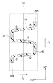
図4には、本発明の第二実施形態に係る車両エネルギ吸収構造30が断面図にて示されている。本発明の第二実施形態に係る車両エネルギ吸収構造30は、本発明の第一実施形態に係る車両エネルギ吸収構造10に対して、クラッシュボックス16の代わりにクラッシュボックス36を備えた構成とされている。
FIG. 4 is a sectional view showing a vehicle
この本発明の第二実施形態に係る車両エネルギ吸収構造30において、クラッシュボックス36は、一対の自由端36A,36Bが領域D以外の領域に配置された構成とされており、一例として、一対の自由端36A,36Bが領域A及び領域Bにそれぞれ配置された構成とされている。また、クラッシュボックス36は、領域C及び領域Dに跨るように配置された谷部38を有する構成とされている。なお、クラッシュボックス36が、例えば、CFRP製とされ、且つ、車両前後方向に作用する衝撃荷重のエネルギを吸収可能な構成とされていることは、上述のクラッシュボックス16と同一である。
In the vehicle
次に、本発明の第二実施形態の作用及び効果について説明する。 Next, the operation and effect of the second embodiment of the present invention will be described.
例えば、本発明の第二実施形態に係る車両エネルギ吸収構造30が適用された車両が車高の低いスポーツタイプ等の車種とされることにより、バンパリインフォースメント12の位置が衝突体70に対して相対的に低い場合には、車両前後方向に対して車両幅方向外側に角度があるだけでなく車両上下方向上側にも角度がある方向から衝突体70がバンパリインフォースメント12に斜めに衝突する場合がある。この場合には、クラッシュボックス36の根元部に対して、車両前後方向への軸圧縮荷重Fxと、車両幅方向内側への曲げ荷重Fyと、車両上下方向下側への曲げ荷重Fzが作用する。これにより、この曲げ荷重Fy,Fzによる曲げモーメントが最大となるクラッシュボックス36の根元部のうち車両幅方向内側且つ車両上下方向下側の部分、すなわち、領域Dには、上述の表2に示す如く、最大圧縮応力が発生する。
For example, the vehicle to which the vehicle
この点、本発明の第二実施形態に係る車両エネルギ吸収構造30では、上述のように、一対の自由端36A,36Bが領域D以外の領域に配置されている。従って、衝突体70が車両前後方向に対して車両幅方向外側且つ車両上下方向上側に角度がある方向からバンパリインフォースメント12に斜めに衝突する場合でも、クラッシュボックス36の根元部に折れが生じることを抑制することができる。
In this regard, in the vehicle
しかも、本発明の第二実施形態に係る車両エネルギ吸収構造30では、上述のように、車両前後方向視にて開断面状に形成されたクラッシュボックス36の一対の自由端36A,36Bの位置を最適に設定しただけであり、根元部の板厚を増加したり根元部を部分的に閉断面状に形成したりしていないので、クラッシュボックス36の質量の増加も防止できる。
Moreover, in the vehicle
このように、本発明の第二実施形態に係る車両エネルギ吸収構造30によれば、クラッシュボックス36の質量を増加させずに、クラッシュボックス36の根元部の折れを抑制でき、軽量で高効率なクラッシュボックス36によりエネルギ吸収させることができる。
Thus, according to the vehicle
また、本発明の第二実施形態に係る車両エネルギ吸収構造30によれば、クラッシュボックス36には谷部38が形成されている。従って、この谷部38によってクラッシュボックス36の剛性が向上されるので、これにより、クラッシュボックス36の根元部に折れが生じることをより一層効果的に抑制することができる。
Further, according to the vehicle
特に、谷部38は、領域Dを跨ぐように配置されているので、この谷部38によってクラッシュボックス36の根元部のうち圧縮応力の大きい領域Dが位置する部分の耐力を確保することができる。
In particular, since the
以上、本発明の第二実施形態について説明したが、本発明は、上記に限定されるものでなく、その主旨を逸脱しない範囲内において種々変形して実施することが可能であることは勿論である。 As mentioned above, although 2nd embodiment of this invention was described, this invention is not limited above, Of course, it can change and implement variously within the range which does not deviate from the main point. is there.
例えば、上記実施形態において、クラッシュボックス36は、一対の自由端36A,36Bが領域D以外の領域として領域A及び領域Bにそれぞれ配置された構成とされていたが、例えば、図5に示されるように、一対の自由端36A,36Bが領域D以外の領域として領域A及び領域Cにそれぞれ配置された構成とされても良い。
For example, in the above embodiment, the
なお、この図5に示される変形例では、クラッシュボックス36が、主として領域Bに配置された山部40と、主として領域Dに配置された谷部42とを有する構成とされている。このように構成されていても、クラッシュボックス36の剛性を向上させることができる。
In the modification shown in FIG. 5, the
また、特に、谷部42は、領域Dに主として配置されているので、この谷部42によってクラッシュボックス36の根元部のうち圧縮応力の大きい領域Dが位置する部分の耐力を確保することができる。
In particular, since the
また、クラッシュボックス36は、上述の図5に示される変形例以外にも、例えば、図6に示されるように、一対の自由端36A,36Bが領域D以外の領域として領域Aにそれぞれ配置された構成とされても良く、また、例えば、図7に示されるように、一対の自由端36A,36Bが領域D以外の領域として領域Bにそれぞれ配置された構成とされても良く、また、例えば、図8に示されるように、一対の自由端36A,36Bが領域D以外の領域として領域Cにそれぞれ配置された構成とされても良い。
In addition to the modified example shown in FIG. 5 described above, the
なお、本発明の第二実施形態に係る車両エネルギ吸収構造30についても、車両の後部に適用されても良いことは勿論である。
Of course, the vehicle
[第三実施形態]
次に、本発明の第三実施形態について説明する。
[Third embodiment]
Next, a third embodiment of the present invention will be described.
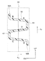
図9には、本発明の第三実施形態に係る車両エネルギ吸収構造50が断面図にて示されている。本発明の第三実施形態に係る車両エネルギ吸収構造50は、本発明の第一実施形態に係る車両エネルギ吸収構造10に対して、クラッシュボックス16の代わりにクラッシュボックス56を備えた構成とされている。
FIG. 9 is a sectional view showing a vehicle
この本発明の第三実施形態に係る車両エネルギ吸収構造50において、クラッシュボックス56は、一対の自由端56A,56Bが領域A以外の領域に配置された構成とされており、一例として、一対の自由端56A,56Bが領域C及び領域Dにそれぞれ配置された構成とされている。また、クラッシュボックス56は、領域A及び領域Bに跨るように配置された山部58を有する構成とされている。なお、クラッシュボックス56が、例えば、CFRP製とされ、且つ、車両前後方向に作用する衝撃荷重のエネルギを吸収可能な構成とされていることは、上述のクラッシュボックス16と同一である。
In the vehicle
次に、本発明の第三実施形態の作用及び効果について説明する。 Next, the operation and effect of the third embodiment of the present invention will be described.
例えば、本発明の第三実施形態に係る車両エネルギ吸収構造50が適用された車両が車高の高いSUVやRV等の車種とされることにより、バンパリインフォースメント12の位置が衝突体70に対して相対的に高い場合には、車両前後方向に対して車両幅方向外側に角度があるだけでなく車両上下方向下側にも角度がある方向から衝突体70がバンパリインフォースメント12に斜めに衝突する場合がある。この場合には、クラッシュボックス56の根元部に対して、車両前後方向への軸圧縮荷重Fxと、車両幅方向内側への曲げ荷重Fyと、車両上下方向上側への曲げ荷重−Fzが作用する。これにより、この曲げ荷重Fy,−Fzによる曲げモーメントが最大となるクラッシュボックス56の根元部のうち車両幅方向内側且つ車両上下方向上側の部分、すなわち、領域Aには、上述の表3に示す如く、最大圧縮応力が発生する。
For example, when the vehicle to which the vehicle
この点、本発明の第三実施形態に係る車両エネルギ吸収構造50では、上述のように、一対の自由端56A,56Bが領域A以外の領域に配置されている。従って、衝突体70が車両前後方向に対して車両幅方向外側且つ車両上下方向下側に角度がある方向からバンパリインフォースメント12に斜めに衝突する場合でも、クラッシュボックス56の根元部に折れが生じることを抑制することができる。
In this regard, in the vehicle
しかも、本発明の第三実施形態に係る車両エネルギ吸収構造50では、上述のように、車両前後方向視にて開断面状に形成されたクラッシュボックス56の一対の自由端56A,56Bの位置を最適に設定しただけであり、根元部の板厚を増加したり根元部を部分的に閉断面状に形成したりしていないので、クラッシュボックス56の質量の増加も防止できる。
Moreover, in the vehicle
このように、本発明の第三実施形態に係る車両エネルギ吸収構造50によれば、クラッシュボックス56の質量を増加させずに、クラッシュボックス56の根元部の折れを抑制でき、軽量で高効率なクラッシュボックス56によりエネルギ吸収させることができる。
As described above, according to the vehicle
また、本発明の第三実施形態に係る車両エネルギ吸収構造50によれば、クラッシュボックス56には山部58が形成されている。従って、この山部58によってクラッシュボックス56の剛性が向上されるので、これにより、クラッシュボックス56の根元部に折れが生じることをより一層効果的に抑制することができる。
Moreover, according to the vehicle
特に、山部58は、領域Aを跨ぐように配置されているので、この山部58によってクラッシュボックス56の根元部のうち圧縮応力の大きい領域Aが位置する部分の耐力を確保することができる。
In particular, since the
以上、本発明の第三実施形態について説明したが、本発明は、上記に限定されるものでなく、その主旨を逸脱しない範囲内において種々変形して実施することが可能であることは勿論である。 The third embodiment of the present invention has been described above. However, the present invention is not limited to the above, and it is needless to say that various modifications can be made without departing from the spirit of the present invention. is there.
例えば、上記実施形態において、クラッシュボックス56は、一対の自由端56A,56Bが領域A以外の領域として領域C及び領域Dにそれぞれ配置された構成とされていたが、例えば、図10に示されるように、一対の自由端56A,56Bが領域A以外の領域として領域B及び領域Dにそれぞれ配置された構成とされても良い。
For example, in the above-described embodiment, the
なお、この図10に示される変形例では、クラッシュボックス56が、主として領域Aに配置された谷部60と、主として領域Cに配置された山部62とを有する構成とされている。このように構成されていても、クラッシュボックス56の剛性を向上させることができる。
In the modification shown in FIG. 10, the
また、特に、谷部60は、領域Aに主として配置されているので、この谷部60によってクラッシュボックス56の根元部のうち圧縮応力の大きい領域Aが位置する部分の耐力を確保することができる。
In particular, since the
また、クラッシュボックス56は、上述の図10に示される変形例以外にも、例えば、図11に示されるように、一対の自由端56A,56Bが領域A以外の領域として領域Dにそれぞれ配置された構成とされても良く、また、例えば、図12に示されるように、一対の自由端56A,56Bが領域A以外の領域として領域Cにそれぞれ配置された構成とされても良く、また、例えば、図13に示されるように、一対の自由端56A,56Bが領域A以外の領域として領域Bにそれぞれ配置された構成とされても良い。
In addition to the modified example shown in FIG. 10 described above, the
なお、本発明の第三実施形態に係る車両エネルギ吸収構造50についても、車両の後部に適用されても良いことは勿論である。
Needless to say, the vehicle
10,30,50 車両エネルギ吸収構造
12 バンパリインフォースメント(荷重入力部材)
14 サイドメンバ(車両骨格部材)
16 クラッシュボックス(エネルギ吸収部材)
16A,16B 自由端
18 山部
20 第一谷部
22 第二谷部
10, 30, 50 Vehicle
14 Side member (vehicle frame member)
16 Crash box (energy absorbing member)
16A,
Claims (5)
それぞれ車両前後方向に延在されて、前記荷重入力部材の車両幅方向中央部に対する車両幅方向両側で且つ車両前後方向一方側に配置された一対の車両骨格部材と、
それぞれ車両前後方向における前記荷重入力部材と前記車両骨格部材との間に設けられて、車両前後方向一方側が前記車両骨格部材に結合され、車両前後方向他方側が前記荷重入力部材に結合されると共に、車両前後方向視にて開断面状に形成され、且つ、車両前後方向視における一対の自由端のうち少なくとも一方が、前記開断面の図心に対する車両幅方向外側の領域に配置された一対のエネルギ吸収部材と、
を備えた車両エネルギ吸収構造。 A load input member extending in the vehicle width direction;
A pair of vehicle skeleton members, each extending in the vehicle longitudinal direction, disposed on both sides in the vehicle width direction with respect to the vehicle width direction central portion of the load input member and on one side in the vehicle longitudinal direction;
Each provided between the load input member and the vehicle skeleton member in the vehicle longitudinal direction, one side in the vehicle longitudinal direction is coupled to the vehicle skeleton member, and the other side in the vehicle longitudinal direction is coupled to the load input member; A pair of energies that are formed in an open cross-sectional shape when viewed in the vehicle longitudinal direction and at least one of the pair of free ends when viewed in the vehicle longitudinal direction is disposed in a region outside the vehicle width direction with respect to the centroid of the open cross-section. An absorbent member;
A vehicle energy absorption structure.
請求項1に記載の車両エネルギ吸収構造。 The pair of free ends are arranged in a region other than the region on the vehicle width direction inner side and the vehicle vertical direction lower side with respect to the centroid of the open section,
The vehicle energy absorption structure according to claim 1.
請求項1に記載の車両エネルギ吸収構造。 The pair of free ends are arranged in a region other than the region on the vehicle width direction inner side and the vehicle vertical direction upper side with respect to the centroid of the open section,
The vehicle energy absorption structure according to claim 1.
前記一対の自由端の他方は、前記開断面の図心に対する車両幅方向外側且つ車両上下方向下側の領域に配置されている、
請求項1〜請求項3のいずれか一項に記載の車両エネルギ吸収構造。 One of the pair of free ends is disposed in a region on the vehicle width direction outer side and the vehicle vertical direction upper side with respect to the centroid of the open section,
The other of the pair of free ends is disposed in a vehicle width direction outer side and a vehicle vertical direction lower side with respect to the centroid of the open section,
The vehicle energy absorption structure according to any one of claims 1 to 3.
車両上下方向における前記一対の自由端の間で前記開断面の図心に対する車両幅方向外側の領域に配置された少なくとも一つの山部と、
車両上下方向における前記自由端の一方と前記山部との間で前記開断面の図心に対する車両幅方向内側且つ車両上下方向上側の領域に配置された第一谷部と、
車両上下方向における前記自由端の他方と前記山部との間で前記開断面の図心に対する車両幅方向内側且つ車両上下方向下側の領域に配置された第二谷部と、を有する、
請求項4に記載の車両エネルギ吸収構造。 The energy absorbing member is
At least one peak portion disposed in a region outside the vehicle width direction with respect to the centroid of the open section between the pair of free ends in the vehicle vertical direction;
A first trough disposed in a region on the vehicle width direction inner side and the vehicle vertical direction upper side with respect to the centroid of the open cross section between one of the free ends in the vehicle vertical direction and the mountain portion;
A second trough disposed in a vehicle width direction inner side and a vehicle vertical direction lower side region with respect to the centroid of the open cross section between the other free end in the vehicle vertical direction and the mountain portion,
The vehicle energy absorption structure according to claim 4.
Priority Applications (1)
| Application Number | Priority Date | Filing Date | Title |
|---|---|---|---|
| JP2008129742A JP2009274663A (en) | 2008-05-16 | 2008-05-16 | Vehicle energy absorbing structure |
Applications Claiming Priority (1)
| Application Number | Priority Date | Filing Date | Title |
|---|---|---|---|
| JP2008129742A JP2009274663A (en) | 2008-05-16 | 2008-05-16 | Vehicle energy absorbing structure |
Publications (1)
| Publication Number | Publication Date |
|---|---|
| JP2009274663A true JP2009274663A (en) | 2009-11-26 |
Family
ID=41440471
Family Applications (1)
| Application Number | Title | Priority Date | Filing Date |
|---|---|---|---|
| JP2008129742A Pending JP2009274663A (en) | 2008-05-16 | 2008-05-16 | Vehicle energy absorbing structure |
Country Status (1)
| Country | Link |
|---|---|
| JP (1) | JP2009274663A (en) |
Cited By (4)
| Publication number | Priority date | Publication date | Assignee | Title |
|---|---|---|---|---|
| WO2019117111A1 (en) | 2017-12-14 | 2019-06-20 | マツダ株式会社 | Shock absorbing structure for vehicles |
| WO2019117110A1 (en) | 2017-12-14 | 2019-06-20 | マツダ株式会社 | Shock absorbing structure for vehicles |
| JP2019104464A (en) * | 2017-12-14 | 2019-06-27 | マツダ株式会社 | Impact absorption structure for vehicle |
| JP2019151132A (en) * | 2018-02-28 | 2019-09-12 | マツダ株式会社 | Front-section vehicular body structure for vehicle |
Citations (5)
| Publication number | Priority date | Publication date | Assignee | Title |
|---|---|---|---|---|
| JPS49106036U (en) * | 1972-12-30 | 1974-09-11 | ||
| JPS59133351U (en) * | 1983-02-28 | 1984-09-06 | いすゞ自動車株式会社 | Mounting structure of automotive resin bumper |
| JPS6158146U (en) * | 1984-09-25 | 1986-04-18 | ||
| JPS62139858U (en) * | 1986-02-28 | 1987-09-03 | ||
| JP2007015626A (en) * | 2005-07-08 | 2007-01-25 | Toyota Industries Corp | Support structure for vehicle bumper |
-
2008
- 2008-05-16 JP JP2008129742A patent/JP2009274663A/en active Pending
Patent Citations (5)
| Publication number | Priority date | Publication date | Assignee | Title |
|---|---|---|---|---|
| JPS49106036U (en) * | 1972-12-30 | 1974-09-11 | ||
| JPS59133351U (en) * | 1983-02-28 | 1984-09-06 | いすゞ自動車株式会社 | Mounting structure of automotive resin bumper |
| JPS6158146U (en) * | 1984-09-25 | 1986-04-18 | ||
| JPS62139858U (en) * | 1986-02-28 | 1987-09-03 | ||
| JP2007015626A (en) * | 2005-07-08 | 2007-01-25 | Toyota Industries Corp | Support structure for vehicle bumper |
Cited By (7)
| Publication number | Priority date | Publication date | Assignee | Title |
|---|---|---|---|---|
| WO2019117111A1 (en) | 2017-12-14 | 2019-06-20 | マツダ株式会社 | Shock absorbing structure for vehicles |
| WO2019117110A1 (en) | 2017-12-14 | 2019-06-20 | マツダ株式会社 | Shock absorbing structure for vehicles |
| JP2019104464A (en) * | 2017-12-14 | 2019-06-27 | マツダ株式会社 | Impact absorption structure for vehicle |
| CN111479724A (en) * | 2017-12-14 | 2020-07-31 | 马自达汽车株式会社 | Impact absorbing structure for vehicle |
| CN111479725A (en) * | 2017-12-14 | 2020-07-31 | 马自达汽车株式会社 | Impact absorbing structure for vehicle |
| US11345295B2 (en) | 2017-12-14 | 2022-05-31 | Mazda Motor Corporation | Impact absorbing structure for vehicles |
| JP2019151132A (en) * | 2018-02-28 | 2019-09-12 | マツダ株式会社 | Front-section vehicular body structure for vehicle |
Similar Documents
| Publication | Publication Date | Title |
|---|---|---|
| JP6459839B2 (en) | Vehicle skeleton structure | |
| JP5556959B2 (en) | Vehicle hood structure | |
| JP6550419B2 (en) | Bumper beam structure | |
| JP5979084B2 (en) | Body front structure | |
| JP4059187B2 (en) | Vehicle hood structure | |
| JP6187447B2 (en) | Vehicle front structure | |
| JP2019051833A (en) | Bumper reinforcement | |
| JP2006015859A (en) | Front vehicle body structure of vehicle | |
| JP4200907B2 (en) | Vehicle hood structure | |
| JP5994321B2 (en) | Body front structure | |
| WO2014156065A1 (en) | Bumper joining structure and crush box | |
| JP5341607B2 (en) | Bumper beam structure for vehicles | |
| JP2009274663A (en) | Vehicle energy absorbing structure | |
| JP4728370B2 (en) | Body front structure | |
| JP5714967B2 (en) | Body shock absorbing structure | |
| JP6237290B2 (en) | Body front structure | |
| JP5803819B2 (en) | Vehicle front structure | |
| JP5875449B2 (en) | Bumper member for vehicles | |
| JP2011111036A (en) | Bumper device | |
| JP6520694B2 (en) | Vehicle front structure | |
| JP2008001149A (en) | Structure of side portion of vehicle | |
| JP2009113767A (en) | Vehicle body front structure | |
| JP6566018B2 (en) | Vehicle shock absorption structure | |
| JP2007176451A (en) | Bumper absorber | |
| JP6211502B2 (en) | Vehicle front structure |
Legal Events
| Date | Code | Title | Description |
|---|---|---|---|
| A621 | Written request for application examination |
Effective date: 20101013 Free format text: JAPANESE INTERMEDIATE CODE: A621 |
|
| A131 | Notification of reasons for refusal |
Effective date: 20120214 Free format text: JAPANESE INTERMEDIATE CODE: A131 |
|
| A977 | Report on retrieval |
Effective date: 20120216 Free format text: JAPANESE INTERMEDIATE CODE: A971007 |
|
| A02 | Decision of refusal |
Effective date: 20120710 Free format text: JAPANESE INTERMEDIATE CODE: A02 |