JP2009261122A - Motor drive device and servo motor - Google Patents

Motor drive device and servo motor Download PDF

Info

Publication number
JP2009261122A
JP2009261122A JP2008106731A JP2008106731A JP2009261122A JP 2009261122 A JP2009261122 A JP 2009261122A JP 2008106731 A JP2008106731 A JP 2008106731A JP 2008106731 A JP2008106731 A JP 2008106731A JP 2009261122 A JP2009261122 A JP 2009261122A
Authority
JP
Japan
Prior art keywords
motor drive
circuit
motor
power supply
rigid substrate
Prior art date
Legal status (The legal status is an assumption and is not a legal conclusion. Google has not performed a legal analysis and makes no representation as to the accuracy of the status listed.)
Pending
Application number
JP2008106731A
Other languages
Japanese (ja)
Inventor
Tomoo Yamagishi
智雄 山岸
Current Assignee (The listed assignees may be inaccurate. Google has not performed a legal analysis and makes no representation or warranty as to the accuracy of the list.)
Mitsuba Corp
Original Assignee
Mitsuba Corp
Priority date (The priority date is an assumption and is not a legal conclusion. Google has not performed a legal analysis and makes no representation as to the accuracy of the date listed.)
Filing date
Publication date
Application filed by Mitsuba Corp filed Critical Mitsuba Corp
Priority to JP2008106731A priority Critical patent/JP2009261122A/en
Publication of JP2009261122A publication Critical patent/JP2009261122A/en
Pending legal-status Critical Current

Links

Images

Abstract

<P>PROBLEM TO BE SOLVED: To provide a motor drive device and a servo motor capable of achieving reductions in size and weight. <P>SOLUTION: The motor drive device includes a motor drive part 44 that has a bridge circuit for switching excitation of each phase coil, and a power circuit part 45 that is connected with an external power supply and that supplies current to the motor drive part 44. The power circuit part 45 is a drive device 7 that is configured to supply a prescribed current to the motor drive part 44 at a prescribed excitation switching timing based on a control signal of an external control device. The motor drive part 44 is mounted on an annular first rigid substrate 41 into which a rotation shaft can be inserted, the power circuit part 45 is mounted on an annular second rigid substrate 42 into which the rotation shaft can be inserted, and the first rigid substrate 41 and the second rigid substrate 42 are connected through a flexible substrate. <P>COPYRIGHT: (C)2010,JPO&INPIT

Description

この発明は、モータ駆動装置、およびこれを用いたサーボモータに関するものである。   The present invention relates to a motor drive device and a servomotor using the same.

一般に、サーボモータを駆動させるモータ駆動装置は、サーボモータに通電するモータ駆動部と、外部電源をモータ駆動部に供給するための電源回路部と、サーボモータの回転軸の回転角度に応じて通電の切換えタイミングを制御する制御部とを有している。
ここで、サーボモータのモータケースの一端に回転軸の回転角度を検出するための回転角度検出装置を設け、さらに、この回転角度検出装置のサーボモータとは反対側の端面にモータ駆動装置を配置したものがある。このように構成することで、サーボモータ、回転角度検出装置、およびモータ駆動装置を一体化し、サーボモータのシステム全体の小型、軽量化を図ろうとしている(例えば、特許文献1、特許文献2参照)。
特開2004−201415号公報 特開2004−208415号公報
In general, a motor drive device that drives a servo motor is energized according to the rotation angle of the rotation shaft of the servo motor, a motor drive unit that energizes the servo motor, a power supply circuit unit that supplies external power to the motor drive unit, and the like. And a control unit for controlling the switching timing.
Here, a rotation angle detection device for detecting the rotation angle of the rotation shaft is provided at one end of the motor case of the servo motor, and a motor drive device is disposed on the end surface opposite to the servo motor of the rotation angle detection device. There is what I did. With this configuration, the servo motor, the rotation angle detection device, and the motor drive device are integrated to reduce the size and weight of the entire servo motor system (see, for example, Patent Document 1 and Patent Document 2). ).
JP 2004-201415 A JP 2004-208415 A

しかしながら、上述の従来技術にあっては、回転角度検出装置やモータ駆動装置をただ単にモータケースの一端に配置しただけであるので、サーボモータ全体としては、モータ軸長が増大したり、モータ外径が大型化したりする。このため、サーボモータのレイアウト性が悪化するという課題がある。   However, in the above-described prior art, since the rotation angle detection device and the motor drive device are simply arranged at one end of the motor case, the servo shaft as a whole increases the motor shaft length, The diameter increases. For this reason, there exists a subject that the layout property of a servomotor deteriorates.

そこで、この発明は、上述した事情に鑑みてなされたものであって、さらに小型、軽量化を図ることができるモータ駆動装置、およびサーボモータを提供するものである。   Therefore, the present invention has been made in view of the above-described circumstances, and provides a motor drive device and a servo motor that can be further reduced in size and weight.

上記の課題を解決するために、請求項1に記載した発明は、各相のコイルへの通電の切換えを行うブリッジ回路を有するモータ駆動部と、外部電源が接続され前記モータ駆動部に電流を供給する電源回路部とを備え、前記電源回路部は、外部制御装置の制御信号に基づいて前記モータ駆動部に所定の電流を所定の通電切換えタイミングで供給するように構成されているモータ駆動装置であって、前記モータ駆動部をモータ軸を挿通可能な環状の第一リジット基板に実装すると共に、前記電源回路部を前記モータ軸を挿通可能な環状の第二リジット基板に実装し、これら第一リジット基板と第二リジット基板とをフレキシブル基板を介して連結したことを特徴とする。
このように構成することで、モータ駆動部が実装されている第一リジット基板と、電源回路部が実装されている第二リジット基板とをモータ軸の各軸端内にモータ軸を取り囲むように配置することが可能になる。
In order to solve the above problems, the invention described in claim 1 is directed to a motor drive unit having a bridge circuit for switching energization to the coils of each phase, and an external power source connected to supply current to the motor drive unit. A motor driving device configured to supply a predetermined current to the motor driving unit at a predetermined energization switching timing based on a control signal of an external control device. The motor drive unit is mounted on an annular first rigid board through which the motor shaft can be inserted, and the power supply circuit unit is mounted on an annular second rigid board through which the motor shaft can be inserted. One rigid board and the second rigid board are connected via a flexible board.
With this configuration, the first rigid board on which the motor drive unit is mounted and the second rigid board on which the power supply circuit unit is mounted are surrounded by the motor shaft within each shaft end of the motor shaft. It becomes possible to arrange.

請求項2に記載した発明は、前記電源回路部に前記モータ軸の回転角度を検出するための回転角度検出装置を設け、前記回転角度検出装置の検出結果に基づいて、前記外部制御装置が通電切換えタイミングを決定することを特徴とする。
このように構成することで、モータ軸の回転角度を検出するための回転角度検出装置を別途設ける必要がなく、回転角度検出装置とモータ駆動装置とを一体化することができる。このため、回転角度検出装置の占有スペースを小さくすることができる。
According to a second aspect of the present invention, a rotation angle detection device for detecting a rotation angle of the motor shaft is provided in the power supply circuit unit, and the external control device is energized based on a detection result of the rotation angle detection device. The switching timing is determined.
With this configuration, it is not necessary to separately provide a rotation angle detection device for detecting the rotation angle of the motor shaft, and the rotation angle detection device and the motor drive device can be integrated. For this reason, the space occupied by the rotation angle detection device can be reduced.

請求項3に記載した発明は、請求項1または請求項2に記載のモータ駆動装置をモータハウジングの一端側に設け、前記フレキシブル基板を湾曲形成して前記第一リジット基板と前記第二リジット基板とを対向配置したことを特徴とするサーボモータとした。
このように構成することで、小型で軽量なサーボモータを提供することが可能になる。
According to a third aspect of the present invention, the motor drive device according to the first or second aspect is provided on one end side of the motor housing, and the flexible substrate is curved to form the first rigid substrate and the second rigid substrate. And a servo motor characterized by being arranged opposite to each other.
With this configuration, a small and lightweight servo motor can be provided.

請求項1に記載した発明によれば、モータ駆動部が実装されている第一リジット基板と、電源回路部が実装されている第二リジット基板とをモータ軸の各軸端内にモータ軸を取り囲むように配置することが可能になる。このため、モータ駆動装置をサーボモータの一端側に配置した場合であっても、従来よりもモータ軸長を短くすることができる。   According to the first aspect of the present invention, the motor shaft is mounted in each shaft end of the motor shaft by connecting the first rigid substrate on which the motor drive unit is mounted and the second rigid substrate on which the power supply circuit unit is mounted. It becomes possible to arrange so that it may surround. For this reason, even if it is a case where a motor drive device is arrange | positioned at the one end side of a servomotor, motor shaft length can be shortened conventionally.

請求項2に記載した発明によれば、モータ軸の回転角度を検出するための回転角度検出装置を別途設ける必要がなく、回転角度検出装置とモータ駆動装置とを一体化することができる。このため、回転角度検出装置の占有スペースを小さくすることができる。よって、モータ全体の小型化を図ることが可能になる。   According to the invention described in claim 2, it is not necessary to separately provide a rotation angle detection device for detecting the rotation angle of the motor shaft, and the rotation angle detection device and the motor drive device can be integrated. For this reason, the space occupied by the rotation angle detection device can be reduced. Therefore, it is possible to reduce the size of the entire motor.

請求項3に記載した発明によれば、小型で軽量なサーボモータを提供することが可能になる。   According to the invention described in claim 3, it is possible to provide a small and lightweight servo motor.

次に、この発明の実施形態を図面に基づいて説明する。
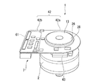
図1、図2に示すように、サーボモータ1は、筒状のハウジング2と、このハウジング2に内嵌固定された固定子3と、固定子3に対して回転自在に設けられた回転子4とを有し、ハウジング2の前端面(図1、図2における左側端)をフロントブラケット5で閉塞すると共に、ハウジング2の後端面(図1、図2における右側端)をエンドブラケット6で閉塞している。また、回転子4のエンドブラケット6側にサーボモータ1を駆動させるための駆動装置7が設けられている。
Next, embodiments of the present invention will be described with reference to the drawings.
As shown in FIGS. 1 and 2, the servo motor 1 includes a cylindrical housing 2, a stator 3 fitted and fixed to the housing 2, and a rotor provided to be rotatable with respect to the stator 3. 4, the front end surface of the housing 2 (the left end in FIGS. 1 and 2) is closed by the front bracket 5, and the rear end surface of the housing 2 (the right end in FIGS. 1 and 2) is closed by the end bracket 6. Blocked. A driving device 7 for driving the servo motor 1 is provided on the end bracket 6 side of the rotor 4.

ハウジング2の外周面には、フロントブラケット5側の周縁に段差によって縮径された縮径部15が形成されている一方、エンドブラケット6側の周縁に段差によって拡径された拡径部17が形成されている。   On the outer peripheral surface of the housing 2, a reduced diameter portion 15 having a diameter reduced by a step is formed on the peripheral edge on the front bracket 5 side, while an enlarged diameter portion 17 having a diameter increased by a step on the peripheral edge on the end bracket 6 side. Is formed.

固定子3は、磁性材料の板材を軸線方向に積層したり、磁性金属粉体を加圧したり(圧粉磁心)することで形成されたものであって、略円筒状の固定子鉄心8を有している。固定子鉄心8は、周壁を形成するコア本体9と、コア本体9から径方向内側に向かって突設された複数のティース部10とが一体成形されたものである。   The stator 3 is formed by laminating plate materials of magnetic material in the axial direction or pressurizing magnetic metal powder (powder magnetic core). The stator core 8 has a substantially cylindrical shape. Have. The stator core 8 is formed by integrally molding a core main body 9 that forms a peripheral wall and a plurality of teeth portions 10 that project from the core main body 9 inward in the radial direction.

コア本体9は、固定子鉄心8の環状の磁路を形成する部分であり、かつハウジング2の内周面に内嵌固定される部分である。
一方、各ティース部10は、巻線11を巻装する部分であって、周方向に等間隔で設けられている。ティース部10は、軸線方向平面視略T字状に形成されている。各ティース部10には、それぞれインシュレータ12が装着され、このインシュレータ12を介して各ティース部10に巻線11が巻装されている。
The core body 9 is a portion that forms an annular magnetic path of the stator core 8 and is a portion that is fitted and fixed to the inner peripheral surface of the housing 2.
On the other hand, each teeth part 10 is a part which winds the coil | winding 11, Comprising: It is provided in the circumferential direction at equal intervals. The teeth portion 10 is formed in a substantially T shape in an axial direction plan view. Each tooth portion 10 is provided with an insulator 12, and a winding 11 is wound around each tooth portion 10 via the insulator 12.

回転子4は、回転軸13と、この回転軸13に外嵌固定されている略円筒状のリングマグネット14とを備えている。回転軸13の一端には、センサマグネット28が取付け部材26を介して設けられている。センサマグネット28は、回転軸13の回転角度を検出するためのエンコーダ30の一方を構成するものであって、2極に着磁されている。取付け部材26は、回転軸13の外嵌固定されている筒部26aと、筒部26aの外側端に設けられた外フランジ部26bとが一体成形されたものである。外フランジ部26bは、センサマグネット28の軸線方向の位置決めを行うためのものである。センサマグネット28は、この一端面が外フランジ部26bに当接するようにして固定されている。   The rotor 4 includes a rotating shaft 13 and a substantially cylindrical ring magnet 14 that is externally fixed to the rotating shaft 13. A sensor magnet 28 is provided at one end of the rotating shaft 13 via an attachment member 26. The sensor magnet 28 constitutes one of the encoders 30 for detecting the rotation angle of the rotary shaft 13 and is magnetized in two poles. The mounting member 26 is formed by integrally molding a cylindrical portion 26a on which the rotary shaft 13 is fitted and fixed, and an outer flange portion 26b provided at the outer end of the cylindrical portion 26a. The outer flange portion 26b is for positioning the sensor magnet 28 in the axial direction. The sensor magnet 28 is fixed such that one end surface thereof is in contact with the outer flange portion 26b.

リングマグネット14は、周方向に磁極が順番に変わるように着磁されている。このような構成のもと、固定子3のティース部10に巻装されている巻線11に電流が流れると磁界が形成され、この磁界とリングマグネット14との間に生じる磁気的な吸引力や反発力によって回転軸13が回転する。   The ring magnet 14 is magnetized so that the magnetic poles change in order in the circumferential direction. Under such a configuration, when a current flows through the winding 11 wound around the tooth portion 10 of the stator 3, a magnetic field is formed, and a magnetic attractive force generated between the magnetic field and the ring magnet 14. The rotating shaft 13 rotates due to the repulsive force.

フロントブラケット5は略円盤状に形成されたものであって、外周縁にハウジング2の縮径部15に勘合する嵌合部20が設けられている。
また、フロントブラケット5には、雌ネジ部21が3箇所周方向に等間隔で刻設されている(図1参照)。フロントブラケット5の径方向中央には、軸受けハウジング23が形成されており、ここに回転軸13の他端を回転自在に支持するための軸受け22が設けられている。
The front bracket 5 is formed in a substantially disc shape, and is provided with a fitting portion 20 that fits into the reduced diameter portion 15 of the housing 2 on the outer peripheral edge.
The front bracket 5 is provided with female screw portions 21 at equal intervals in the circumferential direction (see FIG. 1). A bearing housing 23 is formed in the center of the front bracket 5 in the radial direction, and a bearing 22 for rotatably supporting the other end of the rotating shaft 13 is provided here.

エンドブラケット6は略円盤状に形成されたものであって、外周部に内側に向かって立ち上がるように形成された筒部27が設けられている。筒部27の先端には、ハウジング2の拡径部17に対応するようにインロー部31が形成されている。このインロー部31がハウジング2に内嵌されることにより、エンドブラケット6の位置決めが行われる。   The end bracket 6 is formed in a substantially disk shape, and is provided with a cylindrical portion 27 formed so as to rise inward on the outer peripheral portion. An inlay portion 31 is formed at the tip of the cylindrical portion 27 so as to correspond to the enlarged diameter portion 17 of the housing 2. The end bracket 6 is positioned by fitting the inlay portion 31 into the housing 2.

エンドブラケット6の筒部27よりも内側には、フロントブラケット5の雌ネジ部21に対応する部位にボルト孔(不図示)が形成されている。そして、エンドブラケット6、およびフロントブラケット5は、ボルト18をボルト孔側から挿入し、雌ネジ部21に螺入することによって、ハウジング2を挟持した形で締結固定されるようになっている。   A bolt hole (not shown) is formed in a portion corresponding to the female screw portion 21 of the front bracket 5 on the inner side of the cylindrical portion 27 of the end bracket 6. The end bracket 6 and the front bracket 5 are fastened and fixed in such a manner that the housing 2 is sandwiched by inserting the bolt 18 from the bolt hole side and screwing it into the female screw portion 21.

エンドブラケット6の径方向中央には軸受けハウジング33が形成されており、ここに回転軸13の一端側を回転自在に支持するための軸受け34が設けられている。
また、エンドブラケット6の外周寄りには、後述する駆動装置7のフレキシブル基板43を配索するための開口部35が形成されている。
A bearing housing 33 is formed at the center in the radial direction of the end bracket 6, and a bearing 34 for rotatably supporting one end side of the rotating shaft 13 is provided here.
Further, an opening 35 for routing a flexible substrate 43 of the driving device 7 to be described later is formed near the outer periphery of the end bracket 6.

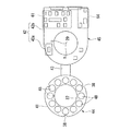
図2〜図6に示すように、駆動装置7は、略円環状に形成されガラスエポキシなどの硬い材質から成る第一リジット基板41と、円環部42aと矩形部42bとが一体成形されガラスエポキシなどの硬い材質から成る第二リジット基板42と、これらリジット基板41,42を連結する可撓可能なフレキシブル基板43とを有している。
なお、図3、図4は駆動装置7の平面図であって、図3は表面の構成を示し、図4は裏面の構成を示している。
As shown in FIGS. 2 to 6, the driving device 7 includes a first rigid substrate 41 made of a hard material such as glass epoxy formed in a substantially annular shape, and an annular portion 42 a and a rectangular portion 42 b that are integrally molded. It has the 2nd rigid board | substrate 42 which consists of hard materials, such as an epoxy, and the flexible substrate 43 which can connect these rigid boards 41 and 42.
3 and 4 are plan views of the driving device 7. FIG. 3 shows the configuration of the front surface, and FIG. 4 shows the configuration of the back surface.

第一リジット基板41は、回転軸13の各軸端内であって、かつエンドブラケット6よりも軸線方向内側に配置されており、固定子3のティース部10に巻装されている各巻線11の端末部(巻き始め端、および巻き終わり端)11aが接続されている。すなわち、第一リジット基板41の径方向中央に形成されている孔37の直径は、回転軸13を挿通可能な大きさに設定されていると共に、第一リジット基板41の外径は、エンドブラケット6の筒部27の内径よりも小さく設定されている。
また、第一リジット基板41には、周方向に等間隔で切り欠き部38が形成されており、これによって第一リジット基板41と各ブラケット5,6を固定するためのボルト18との干渉を回避できるようになっている。
The first rigid substrate 41 is disposed in each axial end of the rotating shaft 13 and on the inner side in the axial direction from the end bracket 6, and each winding 11 wound around the tooth portion 10 of the stator 3. Terminal portions (winding start end and winding end end) 11a are connected. That is, the diameter of the hole 37 formed in the center in the radial direction of the first rigid board 41 is set to a size that allows the rotation shaft 13 to be inserted, and the outer diameter of the first rigid board 41 is set to the end bracket. 6 is set to be smaller than the inner diameter of the cylindrical portion 27.
Further, the first rigid board 41 is formed with notches 38 at equal intervals in the circumferential direction, thereby preventing interference between the first rigid board 41 and the bolts 18 for fixing the brackets 5 and 6. It can be avoided.

一方、第二リジット基板42は、回転軸13の各軸端内であって、かつエンドブラケット6の軸線方向外側にあると共に、回転軸13の一端に設けられたセンサマグネット28よりも軸線方向内側に配置されている。第二リジット基板42は、スタッドボルト39を介してエンドブラケット6に固定されている。第二リジット基板42の円環部42aに形成されている孔40の直径も回転軸13を挿通可能な大きさに設定されている。   On the other hand, the second rigid substrate 42 is located in each axial end of the rotary shaft 13 and outside the end bracket 6 in the axial direction, and further inward in the axial direction than the sensor magnet 28 provided at one end of the rotary shaft 13. Is arranged. The second rigid board 42 is fixed to the end bracket 6 via stud bolts 39. The diameter of the hole 40 formed in the annular portion 42a of the second rigid substrate 42 is also set to a size that allows the rotation shaft 13 to be inserted.

フレキシブル基板43は、第一リジット基板41と第二リジット基板42の円環部42aとの間に配索されている。すなわち、第一リジット基板41と第二リジット基板42は、フレキシブル基板43を湾曲させることでエンドブラケット6を挟んで対向配置された状態になっている。   The flexible substrate 43 is routed between the first rigid substrate 41 and the annular portion 42 a of the second rigid substrate 42. In other words, the first rigid substrate 41 and the second rigid substrate 42 are arranged to face each other with the end bracket 6 sandwiched by curving the flexible substrate 43.

ここで、図3、図4、図7、図8に示すように、第一リジット基板41には、固定子3のティース部10に巻装された各巻線11へ電流を供給するモータ駆動部44が実装されている。
モータ駆動部44は、第一リジット基板41の表面に実装されている複数のプリドライブ回路46、および電流センサ47や、第一リジット基板41の裏面に実装されている複数のスイッチング素子48などを有している。
Here, as shown in FIGS. 3, 4, 7, and 8, a motor driving unit that supplies current to each winding 11 wound around the tooth portion 10 of the stator 3 is provided on the first rigid board 41. 44 is implemented.
The motor drive unit 44 includes a plurality of pre-drive circuits 46 mounted on the surface of the first rigid board 41, a current sensor 47, a plurality of switching elements 48 mounted on the back surface of the first rigid board 41, and the like. Have.

スイッチング素子48は、FET(Field Effect Transistor;電界効果型トランジスタ)等のトランジスタとFET(トランジスタ)のドレイン−ソース間の逆流を防止するダーオードとをモータ駆動電源E1に対して並列に接続した構成を有している(図7、図8参照)。FETとしてはベアチップが用いられ、このベアチップを樹脂モールドすることによって、FETの占有スペースの縮小化を図っている(図4参照)。   The switching element 48 has a configuration in which a transistor such as a field effect transistor (FET) and a diode that prevents reverse flow between the drain and source of the FET (transistor) are connected in parallel to the motor drive power supply E1. (See FIGS. 7 and 8). A bare chip is used as the FET, and the space occupied by the FET is reduced by resin molding the bare chip (see FIG. 4).

スイッチング素子48は、隣接する4つのスイッチング素子48を用いて相毎のHブリッジ回路を形成している。すなわち、図7に示すように、この実施形態のサーボモータ1は、U,V,W相の3相モータの駆動を想定しているので、U相の巻線11に電流を供給する第一ブリッジ回路51と、V相の巻線11に電流を供給する第二ブリッジ回路52と、W相の巻線11に電流を供給する第三ブリッジ回路53をそれぞれスイッチング素子48を4つずつ用いて形成している。   The switching element 48 forms an H-bridge circuit for each phase using four adjacent switching elements 48. That is, as shown in FIG. 7, since the servo motor 1 of this embodiment is supposed to drive a U-phase, V-, and W-phase three-phase motor, a first current is supplied to the U-phase winding 11. A bridge circuit 51, a second bridge circuit 52 that supplies current to the V-phase winding 11, and a third bridge circuit 53 that supplies current to the W-phase winding 11, each using four switching elements 48. Forming.

より具体的には、図8に示すように、第一ブリッジ回路51は、2つのスイッチング素子48をモータ駆動電源E1に対して直列に接続して1つのアーム54を形成し、このアーム54をモータ駆動電源E1に対して2つ並列に接続して構成されている。各アーム54,54のスイッチング素子48,48の間の中点には、U相の巻線11の端末部がそれぞれ接続されている。   More specifically, as shown in FIG. 8, the first bridge circuit 51 connects two switching elements 48 in series with the motor drive power source E1 to form one arm 54. Two motor drive power supplies E1 are connected in parallel. A terminal portion of the U-phase winding 11 is connected to a midpoint between the switching elements 48 of the arms 54 and 54, respectively.

各アーム54のスイッチング素子48は、それぞれプリドライブ回路46に接続されている。プリドライブ回路46は、各スイッチング素子48のON/OFFを制御するものである。U相の巻線11には、プリドライブ回路46によって各スイッチング素子48のONとOFFとを切換えることで所望の向きの電流が流れる。   The switching element 48 of each arm 54 is connected to the pre-drive circuit 46, respectively. The pre-drive circuit 46 controls ON / OFF of each switching element 48. A current in a desired direction flows through the U-phase winding 11 by switching each switching element 48 between ON and OFF by the pre-drive circuit 46.

第二ブリッジ回路52、および第三ブリッジ回路53も第一ブリッジ回路51と同様の構成を有している。第二ブリッジ回路52の各アーム54,54には、スイッチング素子48,48の間の中点にV相の巻線11の端末部がそれぞれ接続されている。第三ブリッジ回路53の各アーム54,54には、スイッチング素子48,48の間の中点にW相の巻線11の端末部がそれぞれ接続されている。   The second bridge circuit 52 and the third bridge circuit 53 have the same configuration as the first bridge circuit 51. Each arm 54, 54 of the second bridge circuit 52 is connected to the end of the V-phase winding 11 at the midpoint between the switching elements 48, 48, respectively. Each arm 54, 54 of the third bridge circuit 53 is connected to the end of the W-phase winding 11 at the midpoint between the switching elements 48, 48.

図7に示すように、巻線11の端末部と各ブリッジ回路51,52,53との間に電流センサ47が設けられている。この電流センサ47は、各相電流(巻線電流)を検出するためのものである。電流センサ47は、各相電流(巻線電流)の検出信号を第二リジット基板42に出力している。
この他に、モータ駆動部44には、温度センサ65が設けられている。温度センサ65は、第一リジット基板41の温度を検出するためのものである。
このように構成された第一リジット基板41は、スイッチング素子48を固定子3側に向けた状態で配設されている(図2参照)。
As shown in FIG. 7, a current sensor 47 is provided between the terminal portion of the winding 11 and each bridge circuit 51, 52, 53. The current sensor 47 is for detecting each phase current (winding current). The current sensor 47 outputs a detection signal of each phase current (winding current) to the second rigid board 42.
In addition, the motor drive unit 44 is provided with a temperature sensor 65. The temperature sensor 65 is for detecting the temperature of the first rigid substrate 41.
The first rigid board 41 configured in this manner is arranged with the switching element 48 facing the stator 3 (see FIG. 2).

第二リジット基板42には、モータ駆動部44に所望の電流を供給する電源回路部45が実装されている。このため、第一リジット基板41と第二リジット基板42は、互いがフレキシブル基板43で接続されている他に、モータ駆動電源E1の電力を電源回路部45からモータ駆動部44へと供給するためのリード線71が接続されている(図1、図2参照)。なお、リード線71に代わってピンヘッダを設けてもよい。
電源回路部45は、第二リジット基板42の表面に実装されているモータ駆動電源コネクタ56、制御回路電源コネクタ57、電源平滑用のアルミ電解コンデンサ58、絶縁インターフェイス回路59、および内部電源回路60や、第二リジット基板42の裏面に実装されている通信回路61、ホール素子29、回転角度検出回路63、過電流検出回路64などを有している。
A power supply circuit unit 45 that supplies a desired current to the motor drive unit 44 is mounted on the second rigid board 42. For this reason, the first rigid substrate 41 and the second rigid substrate 42 are connected to each other by the flexible substrate 43, and also supply power from the motor drive power supply E1 from the power supply circuit unit 45 to the motor drive unit 44. Lead wires 71 are connected (see FIGS. 1 and 2). A pin header may be provided in place of the lead wire 71.
The power supply circuit unit 45 includes a motor drive power supply connector 56, a control circuit power supply connector 57, an aluminum electrolytic capacitor 58 for smoothing the power supply, an insulating interface circuit 59, an internal power supply circuit 60, and the like mounted on the surface of the second rigid board 42. The communication circuit 61, the Hall element 29, the rotation angle detection circuit 63, the overcurrent detection circuit 64, and the like mounted on the back surface of the second rigid board 42 are provided.

また、電源回路部45には、モータ駆動電源コネクタ56を介してモータ駆動電源E1が接続され、制御回路電源コネクタ57を介して各回路を駆動させるための制御回路電源E2が接続されている。さらに、電源E1,E2の他にサーボモータ1の駆動を制御するECU回路基板55が接続されている。   Further, the motor drive power supply E1 is connected to the power supply circuit section 45 through a motor drive power supply connector 56, and a control circuit power supply E2 for driving each circuit is connected through a control circuit power supply connector 57. Further, in addition to the power sources E1 and E2, an ECU circuit board 55 for controlling the drive of the servo motor 1 is connected.

アルミ電解コンデンサ58は、整流された電流の中に含まれている脈流をより直流に近い状態に平滑化するための回路である。アルミ電解コンデンサ58は、モータ駆動電源コネクタ56と接続されている。すなわち、モータ駆動電源E1は、モータ駆動電源コネクタ56、およびアルミ電解コンデンサ58を介してモータ駆動部44の各ブリッジ回路51,52,53に平滑化された電流を供給するようになっている。   The aluminum electrolytic capacitor 58 is a circuit for smoothing the pulsating current contained in the rectified current to a state closer to direct current. Aluminum electrolytic capacitor 58 is connected to motor drive power connector 56. That is, the motor drive power supply E1 supplies a smoothed current to each bridge circuit 51, 52, 53 of the motor drive unit 44 via the motor drive power supply connector 56 and the aluminum electrolytic capacitor 58.

内部電源回路60は、駆動装置7を構成している各回路を駆動させるための回路であって、制御回路電源コネクタ57に接続されている。すなわち、制御回路電源E2は、制御回路電源コネクタ57、および内部電源回路60を介して各回路に電力を供給するようになっている。   The internal power supply circuit 60 is a circuit for driving each circuit constituting the drive device 7 and is connected to the control circuit power supply connector 57. In other words, the control circuit power supply E2 supplies power to each circuit via the control circuit power supply connector 57 and the internal power supply circuit 60.

ホール素子29は、回転軸13の回転角度を検出するためのエンコーダ30の他方を構成するものである。ホール素子29は、センサマグネット28に対応する部位であって、かつ回転軸13を中心に周方向に90°間隔をあけて第二リジット基板42の円環部42aに設けられている(図4参照)。すなわち、この実施形態のサーボモータ1は、回転軸13の回転角度を検出するためのエンコーダを別途設ける必要がなく、駆動装置7にエンコーダ30を組み込んだ状態になっている。   The hall element 29 constitutes the other of the encoder 30 for detecting the rotation angle of the rotary shaft 13. The hall element 29 is a portion corresponding to the sensor magnet 28 and is provided in the annular portion 42a of the second rigid substrate 42 with a 90 ° interval in the circumferential direction around the rotation shaft 13 (FIG. 4). reference). That is, the servo motor 1 of this embodiment does not need to separately provide an encoder for detecting the rotation angle of the rotary shaft 13, and is in a state where the encoder 30 is incorporated in the drive device 7.

ホール素子29は、センサマグネット28から発生する磁界の変化を示す情報として検出し、それぞれ90°位相のずれた正弦波アナログ信号を回転角度検出回路63に出力する。回転角度検出回路63は、ホール素子29からの出力信号に基づいて回転軸13の回転角度を検出し、通信回路61に出力する。
また、電源回路部45は、A/Dコンバータ回路66を備えており、モータ駆動部44に設けられた電流センサ47から出力される各相電流(巻線電流)の検出信号がA/Dコンバータ回路66を介して通信回路61に出力される。
The Hall element 29 detects information indicating a change in the magnetic field generated from the sensor magnet 28, and outputs a sine wave analog signal with a 90 ° phase shift to the rotation angle detection circuit 63. The rotation angle detection circuit 63 detects the rotation angle of the rotary shaft 13 based on the output signal from the hall element 29 and outputs it to the communication circuit 61.
In addition, the power supply circuit unit 45 includes an A / D converter circuit 66, and a detection signal of each phase current (winding current) output from a current sensor 47 provided in the motor drive unit 44 is an A / D converter. The data is output to the communication circuit 61 via the circuit 66.

通信回路61は、LVDS(Low Voltage Differential Signaling)方式に則った差動信号に変換して信号通信を行うものであって、回転角度検出回路63からの出力信号、温度センサ65からの出力信号、および電流センサ47からA/Dコンバータ回路66を介して出力される各相電流(巻線電流)の検出信号をECU回路基板55に出力すると共に、ECU回路基板55から出力される制御信号に基づいて絶縁インターフェイス回路59を介してPWM(パルス幅変調)信号をプリドライブ回路46に出力する。   The communication circuit 61 performs signal communication by converting into a differential signal conforming to the LVDS (Low Voltage Differential Signaling) method. The communication circuit 61 outputs an output signal from the rotation angle detection circuit 63, an output signal from the temperature sensor 65, And a detection signal of each phase current (winding current) output from the current sensor 47 via the A / D converter circuit 66 to the ECU circuit board 55 and based on a control signal output from the ECU circuit board 55. Then, a PWM (pulse width modulation) signal is output to the pre-drive circuit 46 via the insulation interface circuit 59.

ECU回路基板55は、駆動装置7とは別に外部に設けられた制御装置であって、LVDS方式に則った差動信号に変換して信号通信を行う通信回路67と、通信回路67に接続されたサーボ制御回路68とを有している。さらに、サーボ制御回路68は、通信回路69を介して上位制御装置に接続されている。
サーボ制御回路68は、回転角度検出回路63からの出力信号、温度センサ65からの出力信号、および電流センサ47からA/Dコンバータ回路66を介して出力される各相電流(巻線電流)の検出信号に基づいて適正なPWM(パルス幅変調)信号を通信回路67,61、絶縁インターフェイス回路59を介してプリドライブ回路46に出力している。
The ECU circuit board 55 is a control device provided outside the drive device 7. The ECU circuit board 55 is connected to the communication circuit 67, which converts the differential signal in accordance with the LVDS method to perform signal communication, and the communication circuit 67. And a servo control circuit 68. Further, the servo control circuit 68 is connected to the host control device via the communication circuit 69.
The servo control circuit 68 outputs an output signal from the rotation angle detection circuit 63, an output signal from the temperature sensor 65, and each phase current (winding current) output from the current sensor 47 via the A / D converter circuit 66. Based on the detection signal, an appropriate PWM (pulse width modulation) signal is output to the pre-drive circuit 46 via the communication circuits 67 and 61 and the insulation interface circuit 59.

絶縁インターフェイス回路59は、インターフェイス間(通信回路61−絶縁インターフェイス回路59間)の信号電圧系の縁を切るものである。
絶縁インターフェイス回路59には、通信回路61からの信号が入力される他に、過電流検出回路64からの出力信号が入力される。過電流検出回路64は、モータ駆動電源ラインに設けられた抵抗Rを有しており、ここで検出される電流値を絶縁インターフェイス回路59に出力している。絶縁インターフェイス回路59は、この過電流検出回路64により検出された電流値が予め設定されている閾値を超えた場合にプリドライブ回路46へのPWM信号の出力を停止するフェールセーフ回路の役割も有している。
The insulation interface circuit 59 cuts the edge of the signal voltage system between the interfaces (between the communication circuit 61 and the insulation interface circuit 59).
In addition to the signal from the communication circuit 61, the output signal from the overcurrent detection circuit 64 is input to the insulation interface circuit 59. The overcurrent detection circuit 64 has a resistor R provided in the motor drive power supply line, and outputs a current value detected here to the insulation interface circuit 59. The insulation interface circuit 59 also functions as a fail-safe circuit that stops the output of the PWM signal to the pre-drive circuit 46 when the current value detected by the overcurrent detection circuit 64 exceeds a preset threshold value. is doing.

プリドライブ回路46は、絶縁インターフェイス回路59からの出力信号に基づいて各スイッチング素子48のON/OFFを制御している。
このように構成された第二リジット基板42は、表面が第一リジット基板41側に向くように配設されている(図1、図3、図6参照)。
The pre-drive circuit 46 controls ON / OFF of each switching element 48 based on the output signal from the insulation interface circuit 59.
The second rigid board 42 configured in this way is disposed so that the surface faces the first rigid board 41 side (see FIGS. 1, 3, and 6).

ここで、エンドブラケット6には、第二リジット基板42に実装されているアルミ電解コンデンサ58に対応する部位に開口部70が形成されている。この開口部70を形成することによって、アルミ電解コンデンサ58とエンドブラケット6との干渉を回避することができると共に、第二リジット基板42をよりエンドブラケット6側に配設できるようになっている。   Here, an opening 70 is formed in the end bracket 6 at a portion corresponding to the aluminum electrolytic capacitor 58 mounted on the second rigid substrate 42. By forming the opening 70, interference between the aluminum electrolytic capacitor 58 and the end bracket 6 can be avoided, and the second rigid board 42 can be further disposed on the end bracket 6 side.

次に、この実施形態の作用について説明する。
駆動装置7には、モータ駆動電源E1、および制御回路電源E2から電源回路部45に電力が供給される。電源回路部45では、内部電源回路60を通して各回路に制御回路電源E2の電力が供給される。一方、モータ駆動電源E1はアルミ電解コンデンサ58を介してモータ駆動部44に供給される。
Next, the operation of this embodiment will be described.
Power is supplied to the power supply circuit unit 45 from the motor drive power supply E1 and the control circuit power supply E2. In the power supply circuit unit 45, the power of the control circuit power supply E2 is supplied to each circuit through the internal power supply circuit 60. On the other hand, the motor drive power supply E 1 is supplied to the motor drive unit 44 via the aluminum electrolytic capacitor 58.

モータ駆動部44の各ブリッジ回路51,52,53に電流を供給し、サーボモータ1の回転軸13を回転させると、U相、V相、W相の各巻線11に流れる電流がモータ駆動部44の電流センサ47で検出される。各相U,V,Wの電流値は、アナログ信号となってA/Dコンバータ回路66に入力される。A/Dコンバータ回路66は、アナログ信号をパルス状のデジタル信号に変換して通信回路61にシリアル出力する。
また、電流センサ47の電流検出と同時に電源回路部45のホール素子29から回転角度検出回路63を介して回転角度検出信号が通信回路61に出力される。さらに、温度センサ65による第一リジット基板41の温度検出信号も通信回路に出力される。
When current is supplied to each bridge circuit 51, 52, 53 of the motor drive unit 44 and the rotary shaft 13 of the servo motor 1 is rotated, the current flowing through the windings 11 of the U phase, V phase, and W phase is supplied to the motor drive unit. It is detected by 44 current sensors 47. The current values of the phases U, V, and W are input to the A / D converter circuit 66 as analog signals. The A / D converter circuit 66 converts the analog signal into a pulsed digital signal and serially outputs it to the communication circuit 61.
Simultaneously with the current detection of the current sensor 47, a rotation angle detection signal is output from the hall element 29 of the power supply circuit unit 45 to the communication circuit 61 via the rotation angle detection circuit 63. Further, a temperature detection signal of the first rigid board 41 by the temperature sensor 65 is also output to the communication circuit.

各出力信号は、通信回路11からECU回路基板55に出力される。ECU回路基板55では、通信回路67に入力された信号をサーボ制御回路68に出力する。サーボ制御回路68では、各出力信号に基づいて巻線11への通電切り替えのタイミングと通電相の決定とを行う。これによって、各相U,V,Wに対応したPWM信号が出力される。これらPWM信号は、通信回路67,61、および絶縁インターフェイス回路59を介してモータ駆動部44に出力される。   Each output signal is output from the communication circuit 11 to the ECU circuit board 55. In the ECU circuit board 55, the signal input to the communication circuit 67 is output to the servo control circuit 68. The servo control circuit 68 determines the energization switching timing and energization phase for the winding 11 based on each output signal. As a result, PWM signals corresponding to the phases U, V, and W are output. These PWM signals are output to the motor drive unit 44 via the communication circuits 67 and 61 and the insulation interface circuit 59.

モータ駆動部44では、絶縁インターフェイス回路59からプリドライブ回路46に各PWM信号が入力され、各ブリッジ回路51,52,53のスイッチング素子48のON、OFF制御が行われる。スイッチング素子48がONされた経路に接続されたサーボモータ1の巻線11には、モータ駆動電源E1からの電流が流れる。これによって、対応するサーボモータ1の所定の相U,V,Wに電流が流れて回転軸13が回転させられる。   In the motor drive unit 44, each PWM signal is input from the insulation interface circuit 59 to the pre-drive circuit 46, and ON / OFF control of the switching elements 48 of the bridge circuits 51, 52, 53 is performed. A current from the motor drive power source E1 flows through the winding 11 of the servo motor 1 connected to the path where the switching element 48 is turned on. As a result, current flows through the predetermined phases U, V, and W of the corresponding servo motor 1 to rotate the rotating shaft 13.

したがって、上述の実施形態によれば、モータ駆動部44が実装されている第一リジット基板41と、電源回路部45が実装されている第二リジット基板42とを回転軸13の各軸端内であって、回転軸13を取り囲むように配置することが可能になる。このため、駆動装置7を従来のようにサーボモータ1のハウジング2一端側に配置した場合であっても、モータ軸長を短くすることができる。   Therefore, according to the above-described embodiment, the first rigid board 41 on which the motor driving unit 44 is mounted and the second rigid board 42 on which the power supply circuit unit 45 is mounted are arranged in each shaft end of the rotary shaft 13. Thus, it can be arranged so as to surround the rotation shaft 13. For this reason, even if it is a case where the drive device 7 is arrange | positioned at the housing 2 one end side of the servomotor 1 conventionally, a motor shaft length can be shortened.

また、回転軸13の回転角度を検出するためのホール素子62、および回転角度検出回路63を第二リジット基板42に実装しているので、従来のように別体の回転角度検出装置(エンコーダ)を設ける必要がなく、エンコーダ30と駆動装置7とを一体化することができる(図2参照)。このため、エンコーダ30の占有スペースを小さくすることができる。よって、サーボモータ1全体の小型、軽量化を図ることが可能になる。   Further, since the Hall element 62 for detecting the rotation angle of the rotation shaft 13 and the rotation angle detection circuit 63 are mounted on the second rigid board 42, a separate rotation angle detection device (encoder) as in the prior art is provided. Therefore, the encoder 30 and the drive device 7 can be integrated (see FIG. 2). For this reason, the space occupied by the encoder 30 can be reduced. Therefore, it is possible to reduce the size and weight of the entire servo motor 1.

本発明の実施形態におけるサーボモータの分解斜視図である。It is a disassembled perspective view of the servomotor in embodiment of this invention. 本発明の実施形態におけるサーボモータの縦断面図である。It is a longitudinal cross-sectional view of the servomotor in embodiment of this invention. 本発明の実施形態における駆動装置の表面を示す平面図である。It is a top view which shows the surface of the drive device in embodiment of this invention. 本発明の実施形態における駆動装置の裏面を示す平面図である。It is a top view which shows the back surface of the drive device in embodiment of this invention. 本発明の実施形態におけるサーボモータの斜視図である。It is a perspective view of the servomotor in the embodiment of the present invention. 本発明の実施形態におけるサーボモータの斜視図である。It is a perspective view of the servomotor in the embodiment of the present invention. 本発明の実施形態における駆動装置のブロック図である。It is a block diagram of the drive device in the embodiment of the present invention. 本発明の実施形態におけるHブリッジ回路の回路図である。It is a circuit diagram of the H bridge circuit in the embodiment of the present invention.

符号の説明Explanation of symbols

1 サーボモータ
2 ハウジング
3 固定子
4 回転子
5 フロントブラケット
6 エンドブラケット
7 駆動装置(モータ駆動装置)
13 回転軸(モータ軸)
28 センサマグネット
29 ホール素子
30 エンコーダ(回転角度検出装置)
41 第一リジット基板
42 第二リジット基板
42a 円環部
42b 矩形部
43 フレキシブル基板
44 モータ駆動部
45 電源回路部
48 スイッチング素子
51 第一ブリッジ回路(ブリッジ回路)
52 第二ブリッジ回路(ブリッジ回路)
53 第三ブリッジ回路(ブリッジ回路)
54 アーム
55 ECU回路基板(外部制御装置)
E1 モータ駆動電源
E2 制御回路電源
DESCRIPTION OF SYMBOLS 1 Servo motor 2 Housing 3 Stator 4 Rotor 5 Front bracket 6 End bracket 7 Drive device (motor drive device)
13 Rotating shaft (motor shaft)
28 Sensor magnet 29 Hall element 30 Encoder (rotation angle detector)
41 First rigid substrate 42 Second rigid substrate 42a Ring portion 42b Rectangular portion 43 Flexible substrate 44 Motor drive portion 45 Power supply circuit portion 48 Switching element 51 First bridge circuit (bridge circuit)
52 Second bridge circuit (bridge circuit)
53 Third bridge circuit (bridge circuit)
54 Arm 55 ECU circuit board (external control device)
E1 Motor drive power supply E2 Control circuit power supply

Claims (3)

各相のコイルへの通電の切換えを行うブリッジ回路を有するモータ駆動部と、
外部電源が接続され前記モータ駆動部に電流を供給する電源回路部とを備え、
前記電源回路部は、外部制御装置の制御信号に基づいて前記モータ駆動部に所定の電流を所定の通電切換えタイミングで供給するように構成されているモータ駆動装置であって、
前記モータ駆動部をモータ軸を挿通可能な環状の第一リジット基板に実装すると共に、前記電源回路部を前記モータ軸を挿通可能な環状の第二リジット基板に実装し、
これら第一リジット基板と第二リジット基板とをフレキシブル基板を介して連結したことを特徴とするモータ駆動装置。
A motor drive unit having a bridge circuit for switching energization to the coils of each phase;
An external power supply is connected and a power supply circuit section for supplying current to the motor drive section,
The power supply circuit unit is a motor drive device configured to supply a predetermined current to the motor drive unit at a predetermined energization switching timing based on a control signal of an external control device,
The motor drive unit is mounted on an annular first rigid substrate that can be inserted through a motor shaft, and the power supply circuit unit is mounted on an annular second rigid substrate that can be inserted through the motor shaft.
A motor driving device characterized in that the first rigid substrate and the second rigid substrate are connected via a flexible substrate.
前記電源回路部に前記モータ軸の回転角度を検出するための回転角度検出装置を設け、
前記回転角度検出装置の検出結果に基づいて、前記外部制御装置が通電切換えタイミングを決定することを特徴とする請求項1に記載のモータ駆動装置。
A rotation angle detection device for detecting a rotation angle of the motor shaft is provided in the power supply circuit unit,
The motor drive device according to claim 1, wherein the external control device determines an energization switching timing based on a detection result of the rotation angle detection device.
請求項1または請求項2に記載のモータ駆動装置をモータハウジングの一端側に設け、
前記フレキシブル基板を湾曲形成して前記第一リジット基板と前記第二リジット基板とを対向配置したことを特徴とするサーボモータ。

The motor drive device according to claim 1 or 2 is provided on one end side of the motor housing,
A servo motor, wherein the flexible substrate is curved and the first rigid substrate and the second rigid substrate are arranged to face each other.

JP2008106731A 2008-04-16 2008-04-16 Motor drive device and servo motor Pending JP2009261122A (en)

Priority Applications (1)

Application Number Priority Date Filing Date Title
JP2008106731A JP2009261122A (en) 2008-04-16 2008-04-16 Motor drive device and servo motor

Applications Claiming Priority (1)

Application Number Priority Date Filing Date Title
JP2008106731A JP2009261122A (en) 2008-04-16 2008-04-16 Motor drive device and servo motor

Publications (1)

Publication Number Publication Date
JP2009261122A true JP2009261122A (en) 2009-11-05

Family

ID=41387822

Family Applications (1)

Application Number Title Priority Date Filing Date
JP2008106731A Pending JP2009261122A (en) 2008-04-16 2008-04-16 Motor drive device and servo motor

Country Status (1)

Country Link
JP (1) JP2009261122A (en)

Cited By (8)

* Cited by examiner, † Cited by third party
Publication number Priority date Publication date Assignee Title
JP2010099823A (en) * 2008-09-29 2010-05-06 Hitachi Koki Co Ltd Power tool
JP2013138610A (en) * 2013-04-10 2013-07-11 Denso Corp Electrically driven device
JP2014191854A (en) * 2013-03-28 2014-10-06 Rohm Co Ltd Motor drive device
WO2017046841A1 (en) * 2015-09-14 2017-03-23 ルネサスエレクトロニクス株式会社 Electronic device
WO2019065337A1 (en) * 2017-09-29 2019-04-04 日本電産サーボ株式会社 Motor
WO2019065336A1 (en) * 2017-09-29 2019-04-04 日本電産サーボ株式会社 Motor
JP2020099123A (en) * 2018-12-18 2020-06-25 Kyb株式会社 Rotary electric machine
JP2020115713A (en) * 2019-01-17 2020-07-30 日本電産モビリティ株式会社 Motor control device

Cited By (13)

* Cited by examiner, † Cited by third party
Publication number Priority date Publication date Assignee Title
JP2010099823A (en) * 2008-09-29 2010-05-06 Hitachi Koki Co Ltd Power tool
JP2014191854A (en) * 2013-03-28 2014-10-06 Rohm Co Ltd Motor drive device
JP2013138610A (en) * 2013-04-10 2013-07-11 Denso Corp Electrically driven device
WO2017046841A1 (en) * 2015-09-14 2017-03-23 ルネサスエレクトロニクス株式会社 Electronic device
JPWO2017046841A1 (en) * 2015-09-14 2017-11-16 ルネサスエレクトロニクス株式会社 Electronic equipment
US10566879B2 (en) 2015-09-14 2020-02-18 Renesas Electronics Corporation Electronic device
WO2019065336A1 (en) * 2017-09-29 2019-04-04 日本電産サーボ株式会社 Motor
WO2019065337A1 (en) * 2017-09-29 2019-04-04 日本電産サーボ株式会社 Motor
CN111052571A (en) * 2017-09-29 2020-04-21 日本电产伺服有限公司 Motor with a stator having a stator core
CN111052571B (en) * 2017-09-29 2022-06-28 日本电产伺服有限公司 Motor
JP2020099123A (en) * 2018-12-18 2020-06-25 Kyb株式会社 Rotary electric machine
JP7231398B2 (en) 2018-12-18 2023-03-01 Kyb株式会社 Rotating electric machine
JP2020115713A (en) * 2019-01-17 2020-07-30 日本電産モビリティ株式会社 Motor control device

Similar Documents

Publication Publication Date Title
JP2009261122A (en) Motor drive device and servo motor
US7663277B2 (en) Inner-rotor-type brushless motor having built-in bus bar
US10243432B2 (en) Rotation angle detection device
JP5942967B2 (en) Drive device
JP3614380B2 (en) Electric power steering device
JP2010104212A (en) Brushless motor
US9344023B2 (en) Motor device
US7323835B2 (en) Brushless DC motor actuator having remote commutation sensing apparatus
WO2012120588A1 (en) Motor drive device
JP2011200022A (en) Electric drive unit and electric power steering device equipped with the same
JP2010011637A (en) Permanent magnet rotary electric machine and elevator winding machine using the same
EP2715921B1 (en) Motor assembly comprising a brushless dc motor with control electronics
JP2007062433A (en) Electric power steering device
JP2005229721A (en) Motor for electric power steering device
JP2011041355A (en) Motor having built-in drive circuit
JP2007101480A (en) Resolver
JP2007101301A (en) Resolver reference position adjustment method
JP2011083063A (en) Drive controller and motor unit
JP2007132862A (en) Magnetic encoder
JP5204554B2 (en) motor
JP5125434B2 (en) Motor and electric power steering device
JP5523044B2 (en) Drive control device and motor unit
JP2009005530A (en) Brushless motor and printed circuit board therefor
JP5566470B2 (en) Electric power steering motor
KR101180560B1 (en) Brushless motor with built-in current sensors