JP2009242084A - Block moving method and apparatus by single turntable of rail mount type portal crane - Google Patents

Block moving method and apparatus by single turntable of rail mount type portal crane Download PDF

Info

Publication number
JP2009242084A
JP2009242084A JP2008094190A JP2008094190A JP2009242084A JP 2009242084 A JP2009242084 A JP 2009242084A JP 2008094190 A JP2008094190 A JP 2008094190A JP 2008094190 A JP2008094190 A JP 2008094190A JP 2009242084 A JP2009242084 A JP 2009242084A
Authority
JP
Japan
Prior art keywords
rail
block
turntable
rmt
crane
Prior art date
Legal status (The legal status is an assumption and is not a legal conclusion. Google has not performed a legal analysis and makes no representation as to the accuracy of the status listed.)
Withdrawn
Application number
JP2008094190A
Other languages
Japanese (ja)
Inventor
Shinya Kashiwasuga
信哉 栢菅
Current Assignee (The listed assignees may be inaccurate. Google has not performed a legal analysis and makes no representation or warranty as to the accuracy of the list.)
Mitsui Engineering and Shipbuilding Co Ltd
Original Assignee
Mitsui Engineering and Shipbuilding Co Ltd
Priority date (The priority date is an assumption and is not a legal conclusion. Google has not performed a legal analysis and makes no representation as to the accuracy of the date listed.)
Filing date
Publication date
Application filed by Mitsui Engineering and Shipbuilding Co Ltd filed Critical Mitsui Engineering and Shipbuilding Co Ltd
Priority to JP2008094190A priority Critical patent/JP2009242084A/en
Publication of JP2009242084A publication Critical patent/JP2009242084A/en
Withdrawn legal-status Critical Current

Links

Images

Abstract

<P>PROBLEM TO BE SOLVED: To provide a structure and a facility of high maintainability with less failure and to attain the efficient operation of an RMT (rail mount type portal crane) 1 in a container yard 15 by moving the RMT 1 between blocks with mobility in a short time. <P>SOLUTION: A block moving apparatus is provided with a turntable 60 which is a rotation body installed at the ends of inside rails 64 on the abutting side of the adjacent first and second blocks 21, 22, and a turning rail 62 connecting circularly outside rails 65 on the non-abutting side of the first and second blocks 21, 22. <P>COPYRIGHT: (C)2010,JPO&INPIT

Description

本発明は、例えば港湾等のコンテナヤード内において、コンテナの運搬を行うレールマウント式門型クレーン及びコンテナヤード内の設備に関するものである。   The present invention relates to a rail-mounted portal crane that transports containers in a container yard such as a harbor, and equipment in the container yard.

港湾等のコンテナヤードでは、クレーンによって船舶及びトレーラ間の、コンテナの積み下ろしを行っている。   In container yards such as harbors, containers are loaded and unloaded between ships and trailers by cranes.

図8にコンテナヤード15の概観を示す。   FIG. 8 shows an overview of the container yard 15.

コンテナ船等の船舶16によって運搬された20ftあるいは40ftコンテナ等のコンテナ31は、岸壁に設置されたコンテナクレーン17によって荷揚げされ、コンテナヤード15内を走行するトレーラ32に搭載される。トレーラ32に搭載されたコンテナ31は、レール13とコンテナ31を載置する場所であるコンテナスタック29からなる荷役ブロック30に、門型クレーン1によって複数列に整然と並べられ、荷揚げを完了する。これらのコンテナ31は他の船舶16に再び積まれたり、トレーラ32により他の場所へ運搬されたりする。   A container 31 such as a 20 ft or 40 ft container transported by a ship 16 such as a container ship is unloaded by a container crane 17 installed on a quay and mounted on a trailer 32 that travels in a container yard 15. The containers 31 mounted on the trailer 32 are regularly arranged in a plurality of rows by the portal crane 1 on the cargo handling block 30 including the rails 13 and the container stack 29 which is a place on which the containers 31 are placed, and the unloading is completed. These containers 31 are loaded again on other ships 16 or are transported to other places by trailers 32.

ここで、使用されている門型クレーン1は大きく分けて、タイヤにより移動するもの(以下、RTT)と、レール及び車輪の組み合わせで移動するレールマウント式門型クレーン(以下、RMT)がある。RTTはヤード15内を自在に移動することが可能であるが、クレーンは自重が増加すると、それを支えるためのタイヤの個数を多くする必要があり、さらに自重が大きい場合は、タイヤでは支えきれなくなるため、レール式のRMTが採用される。   Here, the portal crane 1 used is roughly classified into a crane that moves by tire (hereinafter, RTT) and a rail-mounted crane (hereinafter, RMT) that moves by a combination of rails and wheels. The RTT can move freely in the yard 15. However, if the weight of the crane increases, it is necessary to increase the number of tires to support it. In order to eliminate this, a rail type RMT is adopted.

また、RMTは、ヤード15内に敷設されたレール13上を移動することで、走行方向が規定され、位置決めが容易となり、吊荷移動の際は荷揺が少ない安定した運搬を実現している。さらに、レール13に沿って移動するため、RMTの側面図である図10に示すケーブルリール20等で給電することが可能となるため、エンジンを搭載したクレーンに比べメンテナンス性が高く、排気ガス等も発生しないため環境性能も高い。   In addition, the RMT moves on the rail 13 laid in the yard 15 so that the traveling direction is defined, positioning becomes easy, and stable transportation with little load fluctuation is realized when moving a suspended load. . Furthermore, since it moves along the rail 13, it is possible to supply power with the cable reel 20 shown in FIG. 10 which is a side view of the RMT. Environmental performance is also high.

他方、RMTは、コンテナヤード15において荷役作業の高効率化や作業の平準化を図るために、例えば図8に示した第1ブロック21の荷役作業量が少なく、第2ブロック22の作業量が多い場合に、第1ブロック21のクレーンC1を第2ブロック22に移動させるという要求があり、また、故障時の対策としてRMTをブロック間(例えば第1ブロック21と第2ブロック22)で移動させるという要求があるが、RMTはブロック間を移動する手段を持たないため、あらかじめひとつのブロックに多数のクレーンを配置しておくことで対応しなくてはならず、設備的に無駄が大きく、非効率であるという問題を抱えている。   On the other hand, in the RMT, in order to increase the efficiency and leveling of the work in the container yard 15, for example, the work load of the first block 21 shown in FIG. In many cases, there is a request to move the crane C1 of the first block 21 to the second block 22, and the RMT is moved between the blocks (for example, the first block 21 and the second block 22) as a countermeasure at the time of failure. However, since RMT does not have a means to move between blocks, it must be dealt with by placing a large number of cranes in one block in advance, which is wasteful in terms of equipment, I have the problem of efficiency.

これに対して、RMTのブロック間移動を行うための発明がなされてきた(例えば特許文献1参照)。   On the other hand, an invention for performing inter-block movement of RMT has been made (see, for example, Patent Document 1).

特許文献1に記載の発明によれば、RMTのブロック間移動を実現するために、図7に示すように、各ブロック(例えば第1ブロック21、第2ブロック22)に対して垂直に交わる方向に、ブロック間移動用レール33を敷設し、RMT37のブロック間移動を実現している。   According to the invention described in Patent Document 1, in order to realize the inter-block movement of the RMT, as shown in FIG. 7, the direction perpendicular to each block (for example, the first block 21 and the second block 22). In addition, an inter-block moving rail 33 is laid to realize the inter-block movement of the RMT 37.

この時、ブロック端部38に移動したRMT37は、前記RMT37下部に設置されたジャッキ36によりジャッキアップすることで、車輪11にかかる荷重を抜き、RMT37と車輪11の間に設置された図示しない旋回装置を作動させ、車輪11を90度回転させる。その後、車輪11がブロック間移動用レール33に乗るように、ジャッキアップしたRMT37を降ろすことで、RMT37の方向は変えずに車輪11のみブロック間移動用レール33の方向に回転させ、ブロック間移動用レール33上を移動するよう構成されている。
特開2004−175515号公報
At this time, the RMT 37 moved to the block end portion 38 is jacked up by the jack 36 installed at the lower portion of the RMT 37, thereby removing the load applied to the wheel 11 and turning (not shown) installed between the RMT 37 and the wheel 11. The device is activated and the wheel 11 is rotated 90 degrees. Thereafter, the RMT 37 that has been jacked up is lowered so that the wheel 11 is on the inter-block movement rail 33, so that only the wheel 11 is rotated in the direction of the inter-block movement rail 33 without changing the direction of the RMT 37, and the inter-block movement is performed. It is configured to move on the rail 33 for use.
JP 2004-175515 A

しかしながら、上記特許文献1の記載の方法においては、図7に示すようにRMT37をジャッキアップし、車輪11を旋回させた後、ブロック間移動用レール33を走行し、移動先であるブロックを走行するため再びジャッキアップ及び車輪11の旋回を行うため、ブロック間の移動に時間及び手間がかかるので、RMT37のブロック間移動を容易かつ機動的に行うことは困難である。   However, in the method described in Patent Document 1, after the RMT 37 is jacked up and the wheel 11 is turned as shown in FIG. 7, the vehicle travels on the inter-block moving rail 33 and travels on the block that is the destination. Therefore, since jack-up and turning of the wheel 11 are performed again, it takes time and labor to move between the blocks, so that it is difficult to easily and dynamically move the RMT 37 between blocks.

また、RMT37をジャッキアップするジャッキ36や、車輪11を旋回させるための旋回装置等の機構が必要となり、この旋回装置には重量物であるRMT37やコンテナ31の重量が常にかかるため、不具合が生じやすくなり、そのためメンテナンス性が低いという問題がある。特に、多忙な港湾で使用される場合は、複雑な機構が潮風の影響を受け、劣化が激しくなり故障の発生頻度が高くなる。   In addition, a mechanism such as a jack 36 for jacking up the RMT 37 and a turning device for turning the wheels 11 is required, and this turning device always takes the weight of the heavy load RMT 37 and the container 31, which causes problems. Therefore, there is a problem that maintenance is low. In particular, when used in a busy port, a complex mechanism is affected by the sea breeze, causing severe deterioration and increasing the frequency of failures.

更に、図7に示すようにレール13に切断部25が発生し、このレール切断部25をクレーンの車輪11が通過する際、レール切断部25の角で車輪11と接触する部分の摩耗が激しくなり、レール13及びブロック間移動用レール33の交換回数が増加してしまう。   Further, as shown in FIG. 7, a cutting portion 25 is generated in the rail 13, and when the crane wheel 11 passes through the rail cutting portion 25, wear of a portion in contact with the wheel 11 at the corner of the rail cutting portion 25 is intense. Thus, the number of exchanges of the rail 13 and the inter-block moving rail 33 is increased.

特に近年、港湾等のコンテナヤード15は24時間フル稼働となる場合も多く、RMT37のメンテナンス頻度が高くなると、コンテナヤード15の稼働率は著しく低下してしまい、さらに、レール磨耗に伴うレール交換作業中は、そのレール13に関わるRMT1の使用が不可能となるため、コンテナヤード15の稼働率の大幅低下は不可避となってしまう。   In particular, in recent years, container yards 15 such as harbors are often in full operation for 24 hours, and if the maintenance frequency of the RMT 37 is increased, the operation rate of the container yard 15 is significantly reduced, and further, rail replacement work accompanying rail wear is performed. Inside, it becomes impossible to use the RMT 1 related to the rail 13, so that a significant decrease in the operation rate of the container yard 15 is unavoidable.

そこで、本発明は上記の課題を解決するためになされたものであり、RMTのブロック間移動を、短時間で機動的に行え、故障が少なくメンテナンス性の高い構造及び設備により実現し、コンテナヤード15内におけるRMTの効率的な運用を実現することを目的とする。   Accordingly, the present invention has been made to solve the above-described problems, and the RMT can be moved between blocks in a short time, and can be realized by a structure and equipment with few failures and high maintainability. The purpose is to realize efficient operation of the RMT within the network.

上記課題を解決するため、請求項1に記載の発明に係る片ターンテーブルによるブロック移動装置は、海上輸送用コンテナの荷役に使用され、走行用レール(2本又は複数本のであってもよく、また平行に敷設してもよい)で構成されたレーンとコンテナを保管するコンテナスタックからなる荷役ブロックに沿って走行用車輪11の駆動力によって移動し、かつ前記車輪11を水平面で回転可能としたレールマウント式門型クレーン(RMT1)が、前記ブロックを複数設けた港湾等のコンテナヤード15で他のブロックに移動するブロック間移動装置であって、隣接した前記ブロック間の端部に設置したターンテーブル60上に片側の脚部の車輪11を停止させ、もう片方の脚部の車輪11を駆動することで、円弧を成した旋回レール62上を自力移動して、隣接したブロックへ(例えば第1ブロック21から第2ブロック22へ)の移動を行うことを特徴とする。   In order to solve the above-mentioned problem, a block moving device using a single turntable according to the invention described in claim 1 is used for cargo handling of a container for sea transportation, and may be a traveling rail (two or a plurality of rails may be used, It may be laid in parallel) and moved by a driving force of the traveling wheel 11 along a cargo handling block consisting of a lane composed of a container and a container stack for storing containers, and the wheel 11 is rotatable on a horizontal plane. A rail-mounted portal crane (RMT1) is an inter-block moving device that moves to another block in a container yard 15 such as a harbor provided with a plurality of the blocks, and is installed at the end between adjacent blocks By turning the wheel 11 on one leg on the table 60 and driving the wheel 11 on the other leg, a turning rail 62 having an arc is formed. The by self moving, and performing the movement of the adjacent blocks (e.g., from the first block 21 to the second block 22).

具体的には、隣り合う第1ブロック21と第2ブロック22の接する側である内側レール64端部にターンテーブル60を設置し、前記ターンテーブル60上にRMT1の車輪11のリムを嵌合して案内するように構成された案内部を形成し、第1ブロック21及び第2ブロック22の接しない側である外側レール65を連結して、前記ターンテーブル60を中心とした円弧状の旋回レール62を形成し、前記ターンテーブル60上にRMT1の一方の車輪11を載置し、他方の車輪11が前記旋回レール62上を自走することで、隣のブロックへの移動が可能となるように構成したことを特徴とする。   Specifically, the turntable 60 is installed at the end of the inner rail 64 that is the side where the adjacent first block 21 and second block 22 are in contact, and the rim of the wheel 11 of the RMT 1 is fitted on the turntable 60. A guide part configured to guide the first block 21 and the outer rail 65 on the side where the first block 21 and the second block 22 are not in contact with each other, and an arcuate swivel rail centering on the turntable 60 62, one wheel 11 of the RMT 1 is placed on the turntable 60, and the other wheel 11 is self-propelled on the turning rail 62 so that it can move to the next block. It is characterized by comprising.

請求項2に記載の発明に係る片ターンテーブルによるブロック移動装置は、隣接した前記ブロック(例えば21,22)間の端部に設置した前記ターンテーブル60上には、前記ブロックの走行レールが延長できる位置にターン用レール61を設け、そのレール上に前記車輪11を嵌合して、車輪の駆動力で移動することを特徴とする。   In the block moving device using a single turntable according to the second aspect of the present invention, a travel rail of the block extends on the turntable 60 installed at an end between adjacent blocks (for example, 21 and 22). A turn rail 61 is provided at a position where it can be formed, and the wheel 11 is fitted on the rail, and is moved by the driving force of the wheel.

具体的には前記ターンテーブル60上の前記案内部が、前記第1ブロック21及び第2ブロック22の内側レール64に連結し、短尺であるターン用レール61を具備し、前記車輪11のリムを嵌合して案内するよう構成したことを特徴とする。   Specifically, the guide portion on the turntable 60 is connected to the inner rails 64 of the first block 21 and the second block 22, and includes a short turn rail 61. It is configured to be fitted and guided.

請求項3に記載の発明に係る片ターンテーブルによるブロック移動装置は、前記ターンテーブル60には、ターンテーブル60上のターン用レール61の位置合わせを検知する位置合わせセンサ62と、位置合わせのための動力装置を備えた回転機構63を持つことを特徴とする。   According to a third aspect of the present invention, in the block moving device using a single turntable, the turntable 60 includes an alignment sensor 62 for detecting the alignment of the turn rail 61 on the turntable 60 and an alignment sensor 62. It has the rotation mechanism 63 provided with the power unit of.

具体的には、前記ターンテーブル60の案内部と前記内側レール64の、位置合わせを検知する位置合わせセンサ52と、前記ターンテーブル60に、位置合わせのための動力装置を伴う回転機構63を具備したことを特徴とする。   Specifically, an alignment sensor 52 for detecting alignment between the guide portion of the turntable 60 and the inner rail 64, and a rotation mechanism 63 with a power device for alignment are provided on the turntable 60. It is characterized by that.

請求項4に記載の発明に係る片ターンテーブルによるブロック移動装置は、前記ターンテーブル60、前記ターン用レール61、及びクレーン走行レール13の上面が、クレーン走行レール付近の地平面34と50mm以内の段差となるようにしたことを特徴とする。   According to a block moving device using a single turntable according to a fourth aspect of the present invention, the top surfaces of the turntable 60, the turn rail 61, and the crane travel rail 13 are within 50 mm from the ground plane 34 near the crane travel rail. It is characterized by a step.

本発明の片ターンテーブルによるブロック移動方法により、従来の方法に比べ、RMT1がブロック間を移動する際に、ジャッキアップや旋回等の必要な動作がなくなり、必要とする時間が短縮され、より機動的に、容易にRMT1のブロック間移動を実現することが可能となった。   According to the block moving method using the single turntable of the present invention, when the RMT 1 moves between the blocks, the necessary operations such as jacking up and turning are eliminated, and the required time is shortened and the maneuvering is performed. In particular, it is possible to easily realize the inter-block movement of RMT1.

RMT1が旋回装置やジャッキ36を具備する必要がないため、単純な機構で構成することが可能となった。そのため、RMT1の故障となる要因が減少し、メンテナンス性が向上した。特に港湾等のコンテナヤード15で使用されるRMT1は、潮風の影響等で金属の劣化が激しくなるため、より単純な構造で故障が少ない機械であることが望まれ、本発明はその要求を満たすものである。   Since it is not necessary for the RMT 1 to include the swivel device or the jack 36, it is possible to configure the RMT 1 with a simple mechanism. As a result, the factors causing the failure of RMT1 are reduced, and the maintainability is improved. In particular, the RMT 1 used in a container yard 15 such as a harbor is likely to be a machine with a simpler structure and less failure because the metal deteriorates severely due to the influence of sea breezes, etc., and the present invention satisfies this requirement. Is.

RMT1の片方の車輪11を、ターンテーブル60上でブレーキにより固定し、他方の車輪11を旋回レール62上で回転させることで、RMT1はブロック間を移動するように構成している。ここで、ターンテーブル60は、RMT1の移動に伴う方向転換の影響で、自動的に回転するため、特に大きな動力を必要とせず、結果、ターンテーブル60の構造は大きな動力装置を伴わない単純な構造とすることができ、メンテナンス性が向上する。   One wheel 11 of the RMT 1 is fixed on the turntable 60 by a brake, and the other wheel 11 is rotated on the turning rail 62 so that the RMT 1 moves between the blocks. Here, the turntable 60 automatically rotates due to the influence of the direction change accompanying the movement of the RMT 1, and therefore does not require particularly large power, and as a result, the structure of the turntable 60 is simple without a large power unit. The structure can be improved, and the maintainability is improved.

また、ターンテーブル60上に敷設されたターン用レール61及び旋回レール62上面をコンテナヤード15の地平面34と50mm以内の小さな段差となるように敷設することで、トレーラ32の走行に支障が出ないように構成している。   In addition, the upper surface of the turn rail 61 and the turning rail 62 laid on the turntable 60 is laid so as to have a small step within 50 mm from the ground plane 34 of the container yard 15, thereby hindering the travel of the trailer 32. It is configured so that there is no.

さらに、ターンテーブル60の案内部と、ブロックのレール13の位置合わせのための位置合わせセンサ52を設置することで、レールの連絡を正確なものとし、RMT1の脱線や脱輪等の事故を防ぐことを可能とした。   Furthermore, by installing the alignment sensor 52 for aligning the guide portion of the turntable 60 and the rail 13 of the block, the rail connection is made accurate and accidents such as derailment and derailment of the RMT 1 are prevented. Made it possible.

以下に、本発明の実施形態について、図面を参照して説明する。   Embodiments of the present invention will be described below with reference to the drawings.

図1は本発明の概略の平面図であり、RMT1が第1ブロック21から第2ブロック22に、ターンテーブル60を利用して移動する様子を示している。   FIG. 1 is a schematic plan view of the present invention, showing how the RMT 1 moves from the first block 21 to the second block 22 using the turntable 60.

図2はターンテーブル60の拡大平面図、図3は図2のA−A断面図である。   2 is an enlarged plan view of the turntable 60, and FIG. 3 is a cross-sectional view taken along the line AA of FIG.

図4及び図5は本発明である片ターンテーブルによるブロック移動方法及び装置の、コンテナヤード15内における実施例を示している。   4 and 5 show an embodiment in the container yard 15 of the block moving method and apparatus using the single turntable according to the present invention.

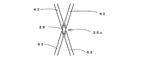
図6は旋回レール62交差部の拡大図を示している。   FIG. 6 shows an enlarged view of the intersection of the turning rails 62.

図9はRMT1の荷役時の概略図であり、レールマウント式門型クレーンであるRMT1がコンテナ31をトロリ12で吊り上げ、待機しているトレーラ32に搭載する様子を示している。RMT1は移動の際、車輪11を利用する。   FIG. 9 is a schematic view when the RMT 1 is loaded and shows a state in which the RMT 1 which is a rail-mounted portal crane lifts the container 31 with the trolley 12 and mounts it on the waiting trailer 32. The RMT 1 uses the wheels 11 when moving.

図10はRMT1の側面図である。RMT1は、下部に配置された支持部35を介して設置された複数の車輪11によりレール13上を移動する。   FIG. 10 is a side view of the RMT 1. The RMT 1 moves on the rail 13 by a plurality of wheels 11 installed via a support portion 35 disposed in the lower part.

図1に示すように、隣接する第1ブロック21と第2ブロック22の、外側レール65は円弧状の旋回レール62により連絡され、内側レール64はターンテーブル60のターン用レール61に連絡され、全体として略U字型になるように構成されている。   As shown in FIG. 1, the outer rail 65 of the adjacent first block 21 and second block 22 is connected by an arcuate swivel rail 62, and the inner rail 64 is connected to a turn rail 61 of the turntable 60, It is comprised so that it may become a substantially U shape as a whole.

例えば、第1ブロック21から第2ブロック22にRMT1を移動させる場合、まず第1ブロック21端部にRMT1を移動させ、RMT1の片方の車輪11をターンテーブル60上に載せる。この時、ターンテーブル60に載っている方の車輪11はブレーキによりロックし、他方の旋回レール62上の車輪11を回転させ、旋回レール62上を移動させる。   For example, when the RMT 1 is moved from the first block 21 to the second block 22, the RMT 1 is first moved to the end of the first block 21 and one wheel 11 of the RMT 1 is placed on the turntable 60. At this time, the wheel 11 on the turntable 60 is locked by the brake, and the wheel 11 on the other turning rail 62 is rotated to move on the turning rail 62.

RMT1は旋回レール62上を移動するとともに、RMT1が回転するため、その外力によりターンテーブル60は回転する。その後、RMT1が移動先ブロックである第2ブロック22正面に移動完了後、ターンテーブル60に載っている車輪11のブレーキを解除することで、第2ブロック22への移動を完了する。   Since RMT1 moves on the turning rail 62 and RMT1 rotates, the turntable 60 rotates by the external force. After that, after the RMT1 has finished moving to the front of the second block 22, which is the destination block, the movement of the wheel 11 placed on the turntable 60 is released, thereby completing the movement to the second block 22.

図2に示すように、内側レール64端部はレール切断部25を介して、ターン用レール61に連絡されており、この連絡を正確に行うための、位置合わせセンサ52を設置している。   As shown in FIG. 2, the end portion of the inner rail 64 is connected to the turn rail 61 via the rail cutting portion 25, and an alignment sensor 52 is installed to accurately perform this communication.

内側レール64とターン用レール61が直線上に位置していない場合、RMT1の脱線や転倒の原因となるため、位置合わせセンサ52は、ターンテーブル60の方向を監視している。   If the inner rail 64 and the turn rail 61 are not positioned on a straight line, the RMT 1 may be derailed or toppled over, so the alignment sensor 52 monitors the direction of the turntable 60.

また、車輪11がターンテーブル60からはみ出さない位置に搭載されているかを監視するための車輪センサ53を搭載してもよい。   Moreover, you may mount the wheel sensor 53 for monitoring whether the wheel 11 is mounted in the position which does not protrude from the turntable 60. FIG.

図3は、図2のA−A断面図を示している。ターン用レール61上面は、地平面34との段差が50mm以内となるように敷設することで、トレーラ32等のコンテナヤード15内を移動する他の移動体に与える影響を少なくしている。   FIG. 3 is a cross-sectional view taken along the line AA in FIG. By laying the upper surface of the turn rail 61 so that the level difference with the ground plane 34 is within 50 mm, the influence on other moving bodies moving in the container yard 15 such as the trailer 32 is reduced.

また、何らかの原因でターンテーブル60が回転してしまい、内側レール64とターン用レール61の位置がずれた場合、この位置ずれを解消するためにターンテーブル60を回転させる回転機構63を設置している。ターンテーブル60の位置合わせを行うための回転機構63であるため、併設される駆動装置の出力はそれほど大きなものを必要としない。   In addition, when the turntable 60 is rotated for some reason and the inner rail 64 and the turn rail 61 are displaced from each other, a rotation mechanism 63 that rotates the turntable 60 is installed to eliminate the displacement. Yes. Since it is the rotation mechanism 63 for aligning the turntable 60, the output of the drive device provided side by side does not need to be so large.

図4は、2つのブロック毎にターンテーブル60と旋回レール62を設けた際の実施例を示している。   FIG. 4 shows an embodiment in which a turntable 60 and a turning rail 62 are provided for every two blocks.

図5は、すべてのブロック間にターンテーブル60と旋回レール62を設けた際の実施例を示している。図5のように構成することで、敷設する旋回レール62及びターンテーブル60の量が図4の場合と比べ多くなるが、RMT1を任意のすべてのブロックに移動させることが可能となる。   FIG. 5 shows an embodiment in which a turntable 60 and a turning rail 62 are provided between all blocks. By configuring as shown in FIG. 5, the amount of the turning rail 62 and the turntable 60 to be laid increases compared to the case of FIG. 4, but the RMT 1 can be moved to any arbitrary block.

図6は旋回レール62交差部であるX状交差部25aの拡大図を示している。旋回レール62上をRMT1が通過可能なように、旋回レール62は斜めに切断され、短尺レール26により連結されるよう構成されている。   FIG. 6 shows an enlarged view of the X-shaped intersection 25a which is the intersection of the turning rails 62. The swing rail 62 is obliquely cut and connected by the short rail 26 so that the RMT 1 can pass over the swing rail 62.

上述のように、本発明の片ターンテーブルによるブロック移動方法及び装置により、RMT1のブロック間移動を、短時間で機動的に行え、故障が少なくメンテナンス性の高い構造及び設備により実現し、コンテナヤード15内におけるRMT1の効率的な運用が可能となった。   As described above, the block moving method and apparatus using the single turntable according to the present invention enables the movement of the RMT 1 between blocks in a short time, and is realized by a structure and equipment with less failure and high maintainability. 15 enables efficient operation of RMT1.

本発明の片ターンテーブルによるブロック移動装置の概略を示した平面図である。It is the top view which showed the outline of the block moving apparatus by the single turntable of this invention. 本発明の片ターンテーブル周辺部の拡大図である。It is an enlarged view of the one turntable periphery part of this invention. 本発明の片ターンテーブルの断面図である。It is sectional drawing of the single turntable of this invention. 本発明の実施例の概略図である。It is the schematic of the Example of this invention. 本発明の実施例の概略図である。It is the schematic of the Example of this invention. 旋回レール交差部の拡大図である。It is an enlarged view of a turning rail intersection. 従来のレーン間移動装置の概略図である。It is the schematic of the conventional interlane moving apparatus. 港湾等のコンテナヤード全体を示した概略図である。It is the schematic which showed the whole container yards, such as a port. RMTによる荷役の状態を示した概略図である。It is the schematic which showed the state of the cargo handling by RMT. RMTの側面図である。It is a side view of RMT.

符号の説明Explanation of symbols

1 レールマウント式門型クレーン(RMT)
11 車輪
15 コンテナヤード
29 コンテナスタック
30 荷役ブロック(ブロック)
52 位置合わせセンサ
53 車輪センサ
60 ターンテーブル
61 ターン用レール
62 旋回レール
63 回転機構
64 内側レール
65 外側レール
1 Rail-mounted portal crane (RMT)
11 Wheel 15 Container Yard 29 Container Stack 30 Cargo Handling Block (Block)
52 Position sensor 53 Wheel sensor 60 Turntable 61 Turn rail 62 Swivel rail 63 Rotating mechanism 64 Inner rail 65 Outer rail

Claims (4)

海上輸送用コンテナの荷役に使用され、走行用レールで構成されたレーンとコンテナを保管するコンテナスタックからなる荷役ブロックに沿って走行用車輪の駆動力によって移動し、かつ前記車輪を水平面で回転可能としたレールマウント式門型クレーンが、前記ブロックを複数設けた港湾等のコンテナヤードで他のブロックに移動するブロック間移動装置であって、隣接した前記ブロック間の端部に設置したターンテーブル上に片側の脚部の車輪を停止させ、もう片方の脚部の車輪を駆動することで、円弧を成した旋回レール上を自力移動して、隣接したブロックへの移動を行うことを特徴とする門型クレーンの荷役ブロック移動装置。   Used for cargo handling of marine transport containers, it can be moved by the driving force of traveling wheels along a cargo handling block consisting of a lane composed of traveling rails and a container stack for storing containers, and the wheels can be rotated in a horizontal plane. The rail-mounted gate crane is a block-to-block moving device that moves to another block in a container yard such as a harbor provided with a plurality of the blocks, on a turntable installed at an end between adjacent blocks The wheel of one leg is stopped and the wheel of the other leg is driven to move on an arcuate turning rail and move to an adjacent block. A cargo handling block moving device for portal cranes. 隣接した前記ブロック間の端部に設置した前記ターンテーブル上には、前記ブロックの走行レールが延長できる位置にターン用レールを設け、そのレール上に前記走行用車輪を嵌合して、車輪の駆動力で移動することを特徴とする請求項1に記載の門型クレーンの荷役ブロック移動装置。   On the turntable installed at the end between the adjacent blocks, a turn rail is provided at a position where the travel rail of the block can be extended, and the travel wheel is fitted on the rail, 2. The cargo handling block moving device for a portal crane according to claim 1, wherein the moving device moves by a driving force. 前記ターンテーブルには、ターンテーブル上のターン用レールの位置合わせを検知する位置合わせセンサと、位置合わせのための動力装置を備えた回転機構を持つことを特徴とする請求項1又は請求項2に記載の門型クレーンの荷役ブロック移動装置。   3. The turntable includes a rotation mechanism including an alignment sensor that detects alignment of a turn rail on the turntable, and a power device for alignment. The cargo handling block moving device of the portal crane described in 1. 前記ターンテーブル、前記ターン用レール、及びクレーン走行レールの上面が、クレーン走行レール付近の地平面と50mm以内の段差となるようにしたことを特徴とする請求項1乃至請求項3に記載の門型クレーンの荷役ブロック移動装置。   4. The gate according to claim 1, wherein upper surfaces of the turntable, the turn rail, and the crane traveling rail have a level difference within 50 mm from a ground plane near the crane traveling rail. Type crane load handling block moving device.
JP2008094190A 2008-03-31 2008-03-31 Block moving method and apparatus by single turntable of rail mount type portal crane Withdrawn JP2009242084A (en)

Priority Applications (1)

Application Number Priority Date Filing Date Title
JP2008094190A JP2009242084A (en) 2008-03-31 2008-03-31 Block moving method and apparatus by single turntable of rail mount type portal crane

Applications Claiming Priority (1)

Application Number Priority Date Filing Date Title
JP2008094190A JP2009242084A (en) 2008-03-31 2008-03-31 Block moving method and apparatus by single turntable of rail mount type portal crane

Publications (1)

Publication Number Publication Date
JP2009242084A true JP2009242084A (en) 2009-10-22

Family

ID=41304466

Family Applications (1)

Application Number Title Priority Date Filing Date
JP2008094190A Withdrawn JP2009242084A (en) 2008-03-31 2008-03-31 Block moving method and apparatus by single turntable of rail mount type portal crane

Country Status (1)

Country Link
JP (1) JP2009242084A (en)

Cited By (3)

* Cited by examiner, † Cited by third party
Publication number Priority date Publication date Assignee Title
JP2012206838A (en) * 2011-03-30 2012-10-25 Mitsui Eng & Shipbuild Co Ltd Container terminal and control method therefor
CN109019354A (en) * 2018-09-17 2018-12-18 袁攀峰 A kind of bridge crane
CN110467114A (en) * 2019-09-11 2019-11-19 中交第四航务工程局有限公司 A kind of gantry crane transverse-moving mechanism and construction method

Cited By (4)

* Cited by examiner, † Cited by third party
Publication number Priority date Publication date Assignee Title
JP2012206838A (en) * 2011-03-30 2012-10-25 Mitsui Eng & Shipbuild Co Ltd Container terminal and control method therefor
CN109019354A (en) * 2018-09-17 2018-12-18 袁攀峰 A kind of bridge crane
CN110467114A (en) * 2019-09-11 2019-11-19 中交第四航务工程局有限公司 A kind of gantry crane transverse-moving mechanism and construction method
CN110467114B (en) * 2019-09-11 2023-11-28 中交第四航务工程局有限公司 Portal crane traversing mechanism and construction method

Similar Documents

Publication Publication Date Title
KR100800227B1 (en) Arrangement scheme of a container wharf and the container loading and unloading process
JP5127535B2 (en) Shuttle type gate crane
JP5363330B2 (en) Plant for transporting cargo to and / or from the ship
JP2014507358A (en) Unloading and loading crane structures, container terminals, and methods for unloading and loading on ships
JP2015522496A (en) Elevated crane and assembly of at least two elevated cranes
WO2013169110A1 (en) Overhead crane, assembly of at least two overhead cranes, automated guided vehicle, and assembly thereof
CN110525578B (en) Pod installation device and method
US20100314346A1 (en) Rear yard crane for automatic terminal
JP2017502896A (en) Stacking crane with intermediate storage area for containers
JP2009242084A (en) Block moving method and apparatus by single turntable of rail mount type portal crane
JP2018100587A (en) Rail transport vehicle
JP2009242081A (en) Lane moving method and device using carriage of rail mount type portal crane
JP2009242085A (en) Switchback type lane moving method and apparatus for rail mount type portal crane
JP7393331B2 (en) transporter
JP2004175515A (en) Crane and container yard
JP2006282386A (en) Equipment arrangement structure in container yard
JP5890226B2 (en) Container terminal and its control method
KR20160134729A (en) Method for manufacturing crane and system for mounting superstructure of crane
JP5027015B2 (en) Cable conveyor
JP2010105773A (en) Block moving method and device by single turntable of rail mount type portal crane
JP2013212884A (en) Container terminal and method of controlling the same
JP2009242090A (en) Belt conveyor type lane moving method and device of rail mount type portal crane
JPH03159897A (en) Heavy cargo loading device for vessel
CN213834337U (en) Multidirectional-moving ship lifting and transferring platform applicable to various ship types
CN220055537U (en) Transportation device for intermodal loading and unloading of container molten iron

Legal Events

Date Code Title Description
A300 Withdrawal of application because of no request for examination

Free format text: JAPANESE INTERMEDIATE CODE: A300

Effective date: 20110607