JP2009238564A - Heating element unit - Google Patents

Heating element unit Download PDF

Info

Publication number
JP2009238564A
JP2009238564A JP2008082809A JP2008082809A JP2009238564A JP 2009238564 A JP2009238564 A JP 2009238564A JP 2008082809 A JP2008082809 A JP 2008082809A JP 2008082809 A JP2008082809 A JP 2008082809A JP 2009238564 A JP2009238564 A JP 2009238564A
Authority
JP
Japan
Prior art keywords
heating element
plate
element unit
reflecting plate
heat
Prior art date
Legal status (The legal status is an assumption and is not a legal conclusion. Google has not performed a legal analysis and makes no representation as to the accuracy of the status listed.)
Pending
Application number
JP2008082809A
Other languages
Japanese (ja)
Inventor
Akira Nishio
章 西尾
Masanori Konishi
政則 小西
Hiroaki Matsuoka
広彰 松岡
Current Assignee (The listed assignees may be inaccurate. Google has not performed a legal analysis and makes no representation or warranty as to the accuracy of the list.)
Panasonic Corp
Original Assignee
Panasonic Corp
Priority date (The priority date is an assumption and is not a legal conclusion. Google has not performed a legal analysis and makes no representation as to the accuracy of the date listed.)
Filing date
Publication date
Application filed by Panasonic Corp filed Critical Panasonic Corp
Priority to JP2008082809A priority Critical patent/JP2009238564A/en
Publication of JP2009238564A publication Critical patent/JP2009238564A/en
Pending legal-status Critical Current

Links

Images

Landscapes

  • Control Of Resistance Heating (AREA)
  • Resistance Heating (AREA)

Abstract

【課題】小型で効率が高く、寿命の長い、各種用途において容易に適応することができる汎用性の高い発熱体ユニットを提供すること目的とする。
【解決手段】発熱体ユニットは、第1のガラス管1を第2のガラス管9と保持部材により汚染物質等から第1のガラス管1を保護する構成とし、また第1のガラス管1と第2のガラス管9との間の空隙に反射板16aを配設し、反射板16aの少なくとも一部に弾性部を有することにより、熱膨張による反射板16aの歪を軽減するよう構成している。
【選択図】図1
An object of the present invention is to provide a highly versatile heating element unit that is small in size, has high efficiency, has a long life, and can be easily adapted to various applications.
A heating element unit is configured to protect a first glass tube from a contaminant or the like by the second glass tube and a holding member. The reflector 16a is disposed in the gap between the second glass tube 9 and an elastic portion is provided in at least a part of the reflector 16a so as to reduce distortion of the reflector 16a due to thermal expansion. Yes.
[Selection] Figure 1

Description

本発明は、熱源として使用される発熱体ユニットに関し、特に被加熱物からの飛散物等の影響を受ける環境下で使用される調理器、乾燥機、電気暖房器、電子装置(複写機、ファクシミリ、プリンタ等を含む)に用いられる発熱体ユニットに関する。 The present invention relates to a heating element unit used as a heat source, and in particular, a cooker, a dryer, an electric heater, an electronic device (a copying machine, a facsimile machine) used in an environment affected by scattered matter from an object to be heated. In addition, the present invention relates to a heating element unit used in a printer.

従来の調理器、乾燥機、電気暖房器、電子装置(複写機、ファクシミリ、プリンタ等を含む)に用いられる発熱体ユニットは、被加熱物からの飛散物等の影響を受ける環境下に対応する為に、第1の透熱管に形成された第1の内部空間内に発熱体構成部を収納し、その第1の透熱管をさらに第2の透熱管に形成された第2の内部空間内に収納する構成を用いた発熱体ユニットが開示されている。(例えば、特許文献1参照。)このように構成された従来の発熱体ユニットは、調理器、乾燥機、電気暖房器、電子装置(複写機、ファクシミリ、プリンタ等を含む)等の加熱装置構成上発熱体ユニットにおいても小型化、高効率化が要求され、第1の透熱管と第2の透熱管の間の狭スペース化及び反射板の薄板化が求められている。
特開2007−149649号公報
The heating element unit used in conventional cookers, dryers, electric heaters, and electronic devices (including copiers, facsimiles, printers, etc.) can be used in an environment that is affected by scattered matter from the object to be heated. For this purpose, the heating element component is housed in the first internal space formed in the first heat transfer tube, and the first heat transfer tube is further formed in the second internal space formed in the second heat transfer tube. There is disclosed a heating element unit using a configuration housed in the housing. (For example, refer to Patent Document 1.) The conventional heating element unit configured as described above has a heating device configuration such as a cooker, a dryer, an electric heater, and an electronic device (including a copying machine, a facsimile, a printer, and the like). The upper heating element unit is also required to be downsized and highly efficient, and the space between the first heat-transmitting tube and the second heat-transmitting tube is required to be narrowed and the reflecting plate is required to be thin.
JP 2007-149649 A

しかしながら、従来の構成において被加熱物からの飛散物等の影響を受けないように発熱体構成部を第1の内部空間に収納する第1の透熱管と、さらに前記第1の透熱管を第2の内部空間に収納する第2の透熱管を配設する構成を用いた発熱体ユニットとし、加熱装置たとえば、調理器、乾燥機、電気暖房器、電子装置(複写機、ファクシミリ、プリンタ等を含む)等に用いられているが、加熱装置構成上発熱体ユニットとして過酷な使用環境においても高寿命で且つ高効率であることはもちろん小型化が求められる。すなわち2重管構成である従来の発熱体ユニットの構成において、第1の透熱管と第2の透熱管の隙間は狭く、第1の透熱管と第2の透熱管の隙間に配置される反射板も薄板となる。したがって、薄板状の反射板は、発熱体からの輻射熱により反射板自体の温度が上昇(約700℃)し反射板の熱膨張によって生じた歪みにより反射板のシワや破損が発生し反射効率が損なわれると言う課題を有していた。   However, in the conventional configuration, the first heat transmission tube that houses the heating element component in the first internal space so as not to be affected by the scattered matter from the object to be heated, and further, the first heat transmission tube 2 is a heating element unit having a configuration in which a second heat-transmitting tube accommodated in the internal space 2 is provided, and a heating device such as a cooker, dryer, electric heater, electronic device (copy machine, facsimile, printer, etc.) However, it is required to be downsized as well as having a long life and high efficiency even in a severe use environment as a heating element unit due to the configuration of the heating device. That is, in the configuration of the conventional heating element unit having a double tube configuration, the gap between the first heat transmission tube and the second heat transmission tube is narrow, and the reflection disposed in the gap between the first heat transmission tube and the second heat transmission tube. The plate is also thin. Therefore, in the thin reflector, the temperature of the reflector itself rises (about 700 ° C.) due to the radiant heat from the heating element, and the reflection plate is wrinkled or damaged due to the distortion caused by the thermal expansion of the reflector. It had the problem of being damaged.

本発明の発熱体ユニットは、従来の課題を解決するもので、反射板の伸縮を吸収する手段を有することにより反射板自体の熱膨張によって生じた歪による反射板のシワや破損を防止し発熱体ユニットとしての寿命が長く、小型で効率が高く、そして各種用途において容易に適応することができる汎用性の高い熱源としての発熱体ユニットを提供すること目的とする。   The heating element unit of the present invention solves the conventional problems, and has a means for absorbing expansion and contraction of the reflecting plate to prevent wrinkles and breakage of the reflecting plate due to distortion caused by the thermal expansion of the reflecting plate itself. It is an object of the present invention to provide a heating element unit as a highly versatile heat source that has a long life as a body unit, is small and highly efficient, and can be easily adapted in various applications.

本発明に係る第1の観点の発熱体ユニットは、発熱部を有する発熱体と、その発熱体の長手方向に位置する端部に取付けられた保持具と、前記発熱体に直接あるいは間接に電気的に接続されて前記発熱体に外部からの電力を供給する電力供給部材と、前記発熱体、前記保持具、及び電力供給部材の一部を第1の内部空間に配置した第1の透熱管と、前記第1の透熱管を第2の内部空間に配置した第2の透熱管と、前記第1の透熱管と第2の透熱管とが所定の隙間を有して配設されるように設けられた保持部材と、前記第1の透熱管と前記第2の透熱管との隙間に配設された反射板とその反射板に設けられた弾性部とを有する反射用部材と、前記反射板を前記発熱体に対して所定の位置に配置されるように前記保持部材、第1の透熱管、あるいは第2の透熱管の少なくとも何れかに直接あるいは間接的
に設けられた位置規制部とによって構成されたものである。
A heating element unit according to a first aspect of the present invention includes a heating element having a heating part, a holder attached to an end located in the longitudinal direction of the heating element, and electric power directly or indirectly to the heating element. Power supply member for supplying external power to the heating element, and a first heat permeable tube in which the heating element, the holder, and a part of the power supply member are arranged in a first internal space And a second heat transfer tube in which the first heat transfer tube is disposed in the second internal space, and the first heat transfer tube and the second heat transfer tube are disposed with a predetermined gap. A reflection member having a holding member provided on the reflector, a reflector disposed in a gap between the first heat-permeable tube and the second heat-permeable tube, and an elastic portion provided on the reflector, and The holding member, the first heat transfer tube, or the reflector so that the reflector is disposed at a predetermined position with respect to the heating element Those constituted by a position regulating portion provided directly or indirectly to at least one of the second diathermic tube.

このように構成された本発明に係る第1の観点の発熱体ユニットは、通電された発熱体の熱により生じる前記反射板への熱ストレスを前記弾性部によって吸収するので、反射手段の破損を防止し高効率で長寿命の発熱体ユニットを可能とする。   The heating element unit according to the first aspect of the present invention configured as described above absorbs the heat stress to the reflecting plate caused by the heat of the energized heating element by the elastic portion, so that the reflecting means is not damaged. Prevents high-efficiency and long-life heating element units.

本発明に係る第2の観点の発熱体ユニットは、上記第1の観点において、前記反射用部材の弾性部は、前記発熱体の長手方向への伸縮を吸収するものである。このように構成された本発明の第2の観点の発熱体ユニットは、前記発熱体の長手方向に生じる前記反射板への熱ストレスを前記弾性部によって吸収するので、反射板の破損を防止し高効率で長寿命の発熱体ユニットを可能とする。   In the heating element unit according to a second aspect of the present invention, in the first aspect, the elastic portion of the reflecting member absorbs expansion and contraction in the longitudinal direction of the heating element. Since the heat generating unit according to the second aspect of the present invention configured as described above absorbs thermal stress to the reflecting plate generated in the longitudinal direction of the heat generating member by the elastic portion, it prevents the reflecting plate from being damaged. Enables a highly efficient and long-life heating element unit.

本発明に係る第3の観点の発熱体ユニットは、上記第1の観点乃至は第2の観点において、前記反射用部材の弾性部は、前記発熱体の長手方向への伸縮を吸収する弾性を有する弾性部材であり、その弾性部材は反射板に機械的に結合されている。このように構成された本発明の第3の観点の発熱体ユニットは、反射板に機械的に結合された前記弾性部材の弾性力等の特性を発熱体の仕様に応じて自由に選択することにより反射板の破損を防止しできるので高効率で長寿命の発熱体ユニットを得ることが出来るとともに、反射板の位置規制も可能な発熱体ユニットを実現できる。   In the heating element unit according to the third aspect of the present invention, in the first aspect or the second aspect, the elastic portion of the reflecting member has elasticity that absorbs expansion and contraction in the longitudinal direction of the heating element. An elastic member that is mechanically coupled to the reflector. The heating element unit according to the third aspect of the present invention configured as described above can freely select characteristics such as elastic force of the elastic member mechanically coupled to the reflector according to the specifications of the heating element. As a result, it is possible to prevent the reflector from being damaged, and thus it is possible to obtain a highly efficient and long-life heating element unit and to realize a heating element unit capable of regulating the position of the reflector.

本発明に係る第4の観点の発熱体ユニットは、上記第1の観点及至第3の観点において前記反射板は金属薄板で形成されている。このように構成された本発明の第4の観点の発熱体ユニットは寿命が長く高効率の発熱体ユニットを実現できる。   In the heating element unit according to the fourth aspect of the present invention, the reflecting plate is formed of a thin metal plate in the first to third aspects. The heat generating unit according to the fourth aspect of the present invention configured as described above can realize a heat generating unit with a long life and high efficiency.

本発明に係る第5の観点の発熱体ユニットは、上記第4の観点において、前記反射板がニッケル、ステンレス鋼(フェライト、オーステナイト等)、又はニクロムの金属薄板で形成されている。このように構成された本発明の第5の観点の発熱体ユニットは寿命が長く高効率の発熱体ユニットを実現できる。   The heating element unit according to a fifth aspect of the present invention is the heating element unit according to the fourth aspect, wherein the reflecting plate is formed of a metal thin plate of nickel, stainless steel (ferrite, austenite, etc.) or nichrome. The heating element unit according to the fifth aspect of the present invention configured as described above can realize a highly efficient heating element unit with a long life.

本発明に係る第6の観点の発熱体ユニットは、上記第3の観点において、前記弾性部材は板材を屈曲し形成されている。このように構成された第6の観点の発熱体ユニットは、反射板の破損を防止し高効率で長寿命な発熱体ユニットを実現できる。   In the heating element unit according to the sixth aspect of the present invention, in the third aspect, the elastic member is formed by bending a plate material. The heating element unit according to the sixth aspect configured as described above can realize a highly efficient and long-life heating element unit that prevents the reflector from being damaged.

本発明に係る第7の観点の発熱体ユニットは、上記第3の観点において、弾性部材は線材をコイル状に形成されている。このように構成された本発明の第7の観点の発熱体ユニットは、反射板の破損を防止し高効率で長寿命とさらには、反射板の位置規制も可能な発熱体ユニットを実現できる。   In the heating element unit according to the seventh aspect of the present invention, in the third aspect, the elastic member is formed of a wire rod in a coil shape. The heating element unit according to the seventh aspect of the present invention configured as described above can realize a heating element unit that prevents damage to the reflecting plate, is highly efficient, has a long life, and can also regulate the position of the reflecting plate.

本発明に係る第8の観点の発熱体ユニットは、上記第6の観点乃至は第7の観点において、前記弾性部材はモリブデンやタングステン、ニッケル、ステンレス鋼、又はニクロムなどの金属で形成されている。このように構成された本発明の第8の観点の発熱体ユニットは、反射板の破損を防止し高効率で長寿命とさらには、反射板の位置規制も可能な発熱体ユニットを実現できる。   In the heating element unit according to the eighth aspect of the present invention, in the sixth aspect to the seventh aspect, the elastic member is formed of a metal such as molybdenum, tungsten, nickel, stainless steel, or nichrome. . The heating element unit according to the eighth aspect of the present invention configured as described above can realize a heating element unit that prevents damage to the reflecting plate, is highly efficient, has a long life, and can also regulate the position of the reflecting plate.

本発明に係る第9の観点の発熱体ユニットは、上記第1の観点乃至第8の観点において、前記発熱体は炭素系物質を含み、かつ発熱体の長手方向に沿って形成された側壁の少なくとも一部に平面部を形成するとともに、その平面部に対向し、かつ前記発熱体を介した前記平面部の裏面側方向に前記発熱体側に向けて熱を反射せしめる前記反射用部材の反射面が配置されるように構成されたものである。このように構成された本発明の第9の観点の発熱体ユニットは、指向性を有する発熱体からの輻射熱の指向性をさらに高める効果があり、高効率で長寿命の発熱体ユニットを可能とする。   A heating element unit according to a ninth aspect of the present invention is the heating element unit according to any one of the first to eighth aspects, wherein the heating element includes a carbon-based material and the side wall formed along the longitudinal direction of the heating element. The reflecting surface of the reflecting member that forms a flat portion at least in part and that opposes the flat portion and reflects heat toward the heating element toward the back surface of the flat portion via the heating element. Is configured to be arranged. The heating element unit according to the ninth aspect of the present invention configured as described above has an effect of further enhancing the directivity of radiant heat from the heating element having directivity, and enables a highly efficient and long-life heating element unit. To do.

本発明に係る第10の観点の発熱体ユニットは、上記第1の観点乃至第8の観点において、前記発熱体は炭素系物質を含み、かつ発熱体の長手方向に沿って形成された側壁の少なくとも一部に平面部を形成するとともに、その平面部の仮想延長面に交差し、かつ前記平面部の裏面側方向に前記発熱体側に向けて反射される前記反射用部材の反射面が配置されるように構成されたものである。このように構成された本発明の第10の観点の発熱体ユニットは、指向性を有する発熱体からの輻射熱を前記反射用部材の反射面によって反射することにより、前記輻射熱の指向性の範囲を広めることができるので、広い範囲を暖めることができるようになるとともに、高効率で長寿命の発熱体ユニットを可能とする。   A heating element unit according to a tenth aspect of the present invention is the heating element unit according to any one of the first to eighth aspects, wherein the heating element includes a carbon-based material and the side wall formed along the longitudinal direction of the heating element. A reflecting surface of the reflecting member that is formed at least in part and intersects a virtual extension surface of the planar portion and is reflected toward the heating element in the rear surface side direction of the planar portion is disposed. It is comprised so that. The heating element unit according to the tenth aspect of the present invention configured in this manner reflects the radiant heat from the directional heating element by the reflecting surface of the reflecting member, thereby reducing the directional range of the radiant heat. Since it can be spread, a wide range can be warmed, and a highly efficient and long-life heating element unit is possible.

本発明の発熱体ユニットによれば、反射板の伸縮を吸収する弾性部が反射用部材に設けられることにより反射板自体の熱膨張によって生じた歪による反射板のシワや破損を防止しできるとともに、寿命が長く、小型で効率が高く、そして各種用途において容易に適応することができる汎用性の高い熱源としての発熱体ユニットを提供することが可能となる。   According to the heating element unit of the present invention, the elastic member that absorbs expansion and contraction of the reflecting plate is provided on the reflecting member, thereby preventing the reflecting plate from being wrinkled or damaged due to distortion caused by the thermal expansion of the reflecting plate itself. Thus, it is possible to provide a heating element unit as a highly versatile heat source that has a long life, is small and highly efficient, and can be easily adapted to various applications.

以下、本発明に係る発熱体ユニットの好適な実施の形態について添付の図面を参照しつつ説明する。   DESCRIPTION OF EMBODIMENTS Hereinafter, preferred embodiments of a heating element unit according to the present invention will be described with reference to the accompanying drawings.

(実施の形態1)
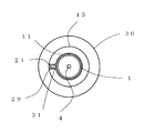
本発明に係る実施の形態1の発熱体ユニットについて図1乃至図9を用いて説明する。図1は実施の形態1の発熱体ユニットの構造を示す正面図、図2は同発熱体ユニットのZ−Z断面における接着剤を省略した場合の断側面図、図3は同発熱体ユニットにおける反射用部材の端部を示す切欠斜視図、図4は反射用部材を示す平面図、図5は同発熱体ユニットにおける反射用部材の異なる例を示す平面図、図6は同発熱体ユニットにおける反射用部材の他の異なる例を示す平面図、図7は同反射用部材の正面図、図8は同発熱体ユニットの一実施例における輻射強度曲線図、図9は同発熱体ユニットの他の実施例における輻射強度曲線図である。先ず、図1乃至図4を用いて実施の形態1の発熱体ユニットを説明する。
(Embodiment 1)
The heating element unit according to the first embodiment of the present invention will be described with reference to FIGS. FIG. 1 is a front view showing the structure of the heating element unit according to the first embodiment, FIG. 2 is a sectional side view when the adhesive in the ZZ cross section of the heating element unit is omitted, and FIG. FIG. 4 is a plan view showing the reflecting member, FIG. 5 is a plan view showing a different example of the reflecting member in the heating element unit, and FIG. 6 is a plan view showing the reflecting member in the same heating element unit. FIG. 7 is a front view of the reflecting member, FIG. 8 is a radiation intensity curve diagram in one embodiment of the heating element unit, and FIG. 9 is the other heating element unit. It is a radiation intensity curve figure in the Example of. First, the heating element unit according to the first embodiment will be described with reference to FIGS. 1 to 4.

図1において、実施の形態1の発熱体ユニットは、熱源である発熱体2aを有する発熱体構成部2を2重の透熱管により収納する構成を有している。実施の形態1の発熱体ユニットにおいて、第1の透熱管は石英ガラス管で形成された円筒形状からなる長尺の第1のガラス管1であり、第1のガラス管1の内部空間(以下、第1の内部空間という。)の長手方向中心軸上には外部からの電力を供給する電力供給部材を両端部にそれぞれ有した発熱体構成部2が配設されている。前記電力供給部材の一部は第1のガラス管1の両端部から外方に露出された状態で配置され、かつ第1のガラス管1の両端部はそれぞれ溶融されて平板状に押し潰されることにより、前記第1の内部空間は封止されている。前記第1の内部空間には発熱体構成部2の主要部品である炭素系物質からなる発熱体2aの酸化を防止するために、アルゴンガス、窒素ガス、又はアルゴンガスと窒素ガスの混合ガス等の不活性ガスが封入されている。尚、第1のガラス管1が発熱体2aの熱に品質上影響されないのであれば発熱体構成部2を前記第1のガラス管1の長手方向中心軸上に配置せず、前記長手方向中心軸に対し略並行な状態で偏芯しても良いことはいうまでも無い。   In FIG. 1, the heating element unit according to the first embodiment has a configuration in which a heating element component 2 having a heating element 2a as a heat source is accommodated by a double heat-transmitting tube. In the heating element unit according to the first embodiment, the first heat-transmitting tube is a long first glass tube 1 having a cylindrical shape formed of a quartz glass tube, and the internal space of the first glass tube 1 (hereinafter referred to as the first glass tube 1). , The first internal space) is provided with heating element constituting portions 2 each having a power supply member for supplying electric power from the outside at both ends. A part of the power supply member is disposed in a state of being exposed outward from both end portions of the first glass tube 1, and both end portions of the first glass tube 1 are melted and crushed into a flat plate shape. Thus, the first internal space is sealed. In the first inner space, argon gas, nitrogen gas, a mixed gas of argon gas and nitrogen gas, or the like is used to prevent oxidation of the heating element 2a made of a carbon-based material, which is a main component of the heating element component 2. The inert gas is enclosed. If the first glass tube 1 is not affected by the heat of the heating element 2a in terms of quality, the heating element component 2 is not disposed on the longitudinal center axis of the first glass tube 1, but the longitudinal center. Needless to say, the shaft may be eccentric in a state substantially parallel to the axis.

発熱体構成部2は、熱輻射体として略平板状からなる長尺の発熱体2aと、この発熱体2aの両端を挟持する保持具3と、前記発熱体2aに直接あるいは間接に電気的に接続されて前記発熱体2aに外部からの電力を供給する電力供給部材とにより構成されている。本実施例の前記電力供給部材は、保持具3の外側端部に取り付けられたコイル部5と、そのコイル部5の外方側他端部に内方側他端部を繋げるスプリング部6と、そのスプリング部6外方側他端部に内方側他端部を繋げる内部リード線4と、第1のガラス管1の両端部から外方側他端部がそれぞれ外方に導出する外部リード線8と、内部リード線部4の外方側他端部と外部リード線8の内方側他端部とを電気的に接続するモリブデン箔7とからなっている。尚、コイル部5、スプリング部6及び内部リード線4は、モリブデン線により一体的に形成されている。さらに、前記モリブデン箔7は第1のガラス管1の両端部をそれぞれ平板状に押し潰して形成された封止部分に挟まれた状態で埋設されている。   The heating element component 2 includes a long heating element 2a having a substantially flat plate shape as a heat radiator, a holder 3 for sandwiching both ends of the heating element 2a, and the heating element 2a directly or indirectly electrically. The power supply member is connected to supply power from the outside to the heating element 2a. The power supply member of the present embodiment includes a coil portion 5 attached to the outer end portion of the holder 3, and a spring portion 6 that connects the other end portion on the inner side to the other end portion on the outer side of the coil portion 5. The internal lead wire 4 connecting the other end on the inner side to the other end on the outer side of the spring part 6 and the outside where the other end on the outer side leads out from both ends of the first glass tube 1 respectively. The lead wire 8 is composed of a molybdenum foil 7 that electrically connects the other end portion on the outer side of the inner lead wire portion 4 and the other end portion on the inner side of the outer lead wire 8. In addition, the coil part 5, the spring part 6, and the internal lead wire 4 are integrally formed with the molybdenum wire. Further, the molybdenum foil 7 is embedded in a state of being sandwiched between sealing portions formed by crushing both end portions of the first glass tube 1 in a flat plate shape.

実施の形態1の発熱体ユニットにおける発熱体2aは、細長い平板状に形成された炭素系物質であり、黒鉛等の結晶化炭素の基材に窒素化合物の抵抗値調整物質、及びアモルファス炭素を加えた混合物により構成されている。この発熱体2aの形状寸法は、例えば、板幅Wが6.0mm、板厚Tが0.5mm、長さLが300mmである。発熱体2aにおいては、板幅Wと板厚Tとの比(W/T)が5以上、即ち板幅Wが板厚Tの5倍以上であるのが望ましい。板幅Wを板厚Tより5倍以上大きい平板状とすることにより、広い平面
(板幅Wを構成する面であり、以下、板幅面という。)から出る熱量が狭い長手方向に沿って形成された側面(板厚Tを構成する面であり、以下、板厚側面という。)から出る熱量より多くなり、平板状の発熱体2aの熱輻射は前記板幅面に対し垂直な方向への輻射となる指向性を持たすことが可能となる。
The heating element 2a in the heating element unit of the first embodiment is a carbon-based material formed in an elongated flat plate shape, and a resistance adjusting substance of a nitrogen compound and amorphous carbon are added to a crystallized carbon substrate such as graphite. Made up of a mixture. The shape of the heating element 2a is, for example, a plate width W of 6.0 mm, a plate thickness T of 0.5 mm, and a length L of 300 mm. In the heating element 2a, it is desirable that the ratio (W / T) between the plate width W and the plate thickness T is 5 or more, that is, the plate width W is 5 times or more of the plate thickness T. By forming the plate width W into a flat plate shape that is at least 5 times larger than the plate thickness T, the amount of heat generated from a wide plane (which is a surface constituting the plate width W, hereinafter referred to as the plate width surface) is formed along a narrow longitudinal direction. The amount of heat emitted from the formed side surface (which is a surface constituting the plate thickness T, hereinafter referred to as the plate thickness side surface) is larger, and the heat radiation of the flat heating element 2a is radiated in a direction perpendicular to the plate width surface. It becomes possible to have directivity that becomes.

実施の形態1の発熱体ユニットにおいては、コイル部5、スプリング部6及び内部リード線4をモリブデン線により形成した例で説明したが、モリブデン線の他にタングステン等の弾性を有する金属線を用いて構成しても良い。又、本例のようにコイル部5から保持具3を介して発熱体2aに電力を供給するようにコイル部5が保持具3の外周面に密着して螺旋状に巻き付けられた場合には、保持具3とコイル部5は電気的に確実に接続されていることが必要である。尚、本例ではコイル部5の外方側他端部(発熱体2aに対し離れた側に位置する端部)にスプリング部6の内方側一端部(発熱体2aに対し近づいた側に位置する端部)を繋ぎ、さらに、そのスプリング部6の外方側他端部に内部リード線4の内方側一端部を繋いだ構成を採用したが、コイル部5を保持具3に巻きつけ、かつコイル部5に繋がれていない内部リード線4の内方側一端を直接あるいはコイル部5以外の別部品を介して間接的に発熱体2aに電気接続するとともに、内部リード線4にスプリング部6を設ける構成でもよいことはいうまでもない。   In the heating element unit of the first embodiment, the coil part 5, the spring part 6 and the internal lead wire 4 are described as being formed of molybdenum wire. However, in addition to the molybdenum wire, an elastic metal wire such as tungsten is used. May be configured. Further, when the coil unit 5 is closely wound on the outer peripheral surface of the holder 3 and is spirally wound so as to supply electric power from the coil unit 5 to the heating element 2a via the holder 3 as in this example. The holder 3 and the coil part 5 need to be electrically and reliably connected. In this example, the other end on the outer side of the coil part 5 (the end located on the side away from the heating element 2a) and the one end on the inner side of the spring part 6 (on the side closer to the heating element 2a). The end portion of the inner lead wire 4 is connected to the other outer end portion of the spring portion 6, and the coil portion 5 is wound around the holder 3. In addition, the inner end of the internal lead wire 4 that is not connected to the coil portion 5 is electrically connected to the heating element 2a directly or indirectly through another component other than the coil portion 5, and the internal lead wire 4 Needless to say, the spring portion 6 may be provided.

又、弾性力を有して螺旋状に形成されたスプリング部6は、発熱体2aに対して張力を与えるものであり、発熱体2aが第1のガラス管1の内部で所望の位置に常に配置されるように位置規制している。このようにコイル部5と内部リード線4との間にスプリング部6を設けることにより、発熱体2aの熱膨張による寸法変化を吸収することが可能となるものである。又、実施の形態1の発熱体ユニットにおいては、スプリング部6を発熱体2aの両端側に設けた例で説明したが、発熱体ユニットの仕様あるいは発熱体2aが配置される状態によっては、スプリング部6を発熱体2aの一端部側すなわち片側端部だけに設けた構成でも可能であることは言うまでもない。又、内部リード線4の外方側他端部は溶接によりモリブデン箔7の内方側一端部に接合されており、モリブデン箔7の外方側他端部には発熱体構成部2に外部からの電力を供給する外部リード線8の内方側一端部が溶接により接合されている。   Further, the spring portion 6 formed in a spiral shape with an elastic force applies tension to the heating element 2 a, and the heating element 2 a is always in a desired position inside the first glass tube 1. The position is regulated so as to be arranged. Thus, by providing the spring part 6 between the coil part 5 and the internal lead wire 4, it becomes possible to absorb the dimensional change by the thermal expansion of the heat generating body 2a. Further, in the heating element unit of the first embodiment, the example in which the spring portions 6 are provided on both ends of the heating element 2a has been described. However, depending on the specifications of the heating element unit or the state in which the heating element 2a is arranged, the spring Needless to say, a configuration in which the portion 6 is provided only on one end portion side of the heating element 2a, that is, on one end portion is also possible. Further, the other end portion on the outer side of the internal lead wire 4 is joined to one end portion on the inner side of the molybdenum foil 7 by welding, and the other end portion on the outer side of the molybdenum foil 7 is externally connected to the heating element component 2. One end portion on the inner side of the external lead wire 8 that supplies electric power from is joined by welding.

上記のように構成された発熱体構成部2を前記第1の内部空間に配置する第1のガラス管1は、第1のガラス管1の外径寸法より内径寸法が大きく、かつ円筒形状からなる長尺の第2の透熱管の内部空間(以下、第2の内部空間という。)に配置される際には、第2のガラス管9の第2の内部空間側に位置することとなる内側壁に対して所定の空隙空間を有して配置されるために、第1のガラス管1の両端部側にそれぞれ位置する外側壁に装着された保持部材10を用いて位置規制を行っている。尚、実施の形態1の発熱体ユニットにおいては、発熱体構成部2(あるいは発熱体2a)、第1のガラス管1、及び第2のガラス管9の各長手方向中心軸は同軸あるいは偏芯し略並行な状態で配置されている。   The first glass tube 1 in which the heating element component 2 configured as described above is arranged in the first internal space has an inner diameter dimension larger than the outer diameter dimension of the first glass tube 1 and has a cylindrical shape. When it is arranged in the internal space of the long second heat-permeable tube (hereinafter referred to as the second internal space), it is located on the second internal space side of the second glass tube 9. In order to be arranged with a predetermined gap space with respect to the inner side wall, the position is regulated using the holding members 10 mounted on the outer side walls respectively positioned on both ends of the first glass tube 1. Yes. In the heating element unit of the first embodiment, the longitudinal axes of the heating element component 2 (or the heating element 2a), the first glass tube 1, and the second glass tube 9 are coaxial or eccentric. However, they are arranged in a substantially parallel state.

保持部材10は、第1のガラス管1及び第2のガラス管9の中心軸に対して交差する一対の対向する端面(一例を示す図1においては、前記中心軸に対して直交する方向(以下、ラジアル方向という)に立設した端面が形成されており、その両端面間を貫通する係合孔11が形成されている。その係合孔11には第1のガラス管1の端部が貫通した状態で係合することにより保持部材10によって第1のガラス管1の端部が保持されるようになっている。発熱体2a側に位置する保持部材10の前記端面すなわち内方側端面に位置する係合孔11の開口周縁部には係合孔11より外形寸法が大きい係止用凹部12が形成されており、その係止用凹部12は第2のガラス管9と係合して保持することとなる。すなわち、この係止用凹部12はその側壁面が第2のガラス管9の外側壁面に当接して第2のガラス管9の前記ラジアル方向への移動を規制し、かつ奥側に位置する底部面が第2のガラス管9の端部に当接して第2のガラス管9の前記長手方向への移動を規制することとなり、第2のガラス管9が保持されることとなる。   The holding member 10 has a pair of opposed end faces that intersect the central axes of the first glass tube 1 and the second glass tube 9 (in FIG. 1 showing an example, a direction orthogonal to the central axis ( Hereinafter, an end face standing in the radial direction is formed, and an engagement hole 11 penetrating between both end faces is formed in the end part of the first glass tube 1. The end of the first glass tube 1 is held by the holding member 10 by being engaged in a state where it penetrates the end face, that is, the inner side of the holding member 10 located on the heating element 2a side. A locking recess 12 having an outer dimension larger than that of the engagement hole 11 is formed at the opening peripheral edge of the engagement hole 11 located on the end surface. The locking recess 12 engages with the second glass tube 9. That is, the locking recess 12 is The side wall surface is in contact with the outer wall surface of the second glass tube 9 to restrict the movement of the second glass tube 9 in the radial direction, and the bottom surface located on the back side is the end of the second glass tube 9. The movement of the second glass tube 9 in the longitudinal direction is restricted by contacting the portion, and the second glass tube 9 is held.

さらに、前記前記係止用凹部12の開口周縁部には、前記係止用凹部12より大きい外形寸法を有する第1の保持用凹部13が形成され、その第1の保持用凹部13と第2のガラス管9の外側壁面との間に生じた第1の隙間空間に接着剤14が塗布されることにより第2のガラス管9は第1の保持用凹部13に固定されることとなる。又、保持部材10は、前記内方側端面に対向する他方の外方側端面(外部リード線8等が位置し、発熱体2aが位置しない側の端面)にも、前記係合孔11より大きい外形寸法を有する第2の保持用凹部15(図2参照)が形成され、その第2の保持用凹部15と第1のガラス管1との間に生じた第2の隙間空間に接着剤14が塗布されることにより第1のガラス管1は第2の保持用凹部15に固定されることとなる。したがって、第1の隙間空間及び第2の隙間空間に接着剤14が塗布されることにより第2のガラス管の第2の内部空間(前記所定の空隙空間を含む)を封止し、前記第2の内部空間への(汚染物質等の進入を防止することとなる。その結果、この保持部材10による第1のガラス管1と第2のガラス管9の保持により、第1のガラス管1と第2のガラス管9との間の隙間を正確に保持できることとなり、信頼性の高い発熱体ユニットを構成できる。   Further, a first holding recess 13 having an outer dimension larger than that of the locking recess 12 is formed at the opening peripheral edge of the locking recess 12, and the first holding recess 13 and the second holding recess 13 are formed. The second glass tube 9 is fixed to the first holding recess 13 by applying the adhesive 14 to the first gap space generated between the outer wall surface of the glass tube 9. In addition, the holding member 10 is also connected to the other outer end surface (the end surface on the side where the external lead wire 8 and the like are not positioned) on the other outer end surface facing the inner end surface. A second holding recess 15 (see FIG. 2) having a large outer dimension is formed, and an adhesive is formed in the second gap space formed between the second holding recess 15 and the first glass tube 1. By applying 14, the first glass tube 1 is fixed to the second holding recess 15. Therefore, the adhesive 14 is applied to the first gap space and the second gap space to seal the second internal space (including the predetermined gap space) of the second glass tube, and 2 (preventing entry of contaminants and the like into the internal space 2. As a result, the first glass tube 1 is retained by the holding of the first glass tube 1 and the second glass tube 9 by the holding member 10. And the second glass tube 9 can be accurately maintained, and a highly reliable heating element unit can be configured.

尚、実施の形態1の発熱体ユニットにおいては、保持部材10によって第1のガラス管1及び第2のガラス管9の保持をそれぞれ行ったが、第1のガラス管1と第2のガラス管9の相対的位置関係を保つことができる位置決め機能を有した保持手段からなる構造物(単数あるいは複数)であれば、図1に示す保持部材10に代えて採用してもよいことは言うまでもない。   In the heating element unit according to the first embodiment, the first glass tube 1 and the second glass tube 9 are respectively held by the holding member 10, but the first glass tube 1 and the second glass tube are respectively held. Needless to say, the structure may be employed in place of the holding member 10 shown in FIG. 1 as long as it is a structure (single or plural) made of holding means having a positioning function capable of maintaining the relative positional relationship 9. .

又、実施の形態1の発熱体ユニットにおいては、前記発熱体ユニットを搭載した加熱装置の構成が第2のガラス管9内の第2の内部空間に被加熱物から飛散する汚染物質等の進入の恐れがある場合を想定して、単品の保持部材10(あるいは第1の保持用凹部13)と第2のガラス管9との間に形成された第1の隙間空間、前記単品の保持部材10(あるいは第2の保持用凹部15)と第1のガラス管1との間に形成された第2の隙間空間にそれぞれに接着剤14を塗布して第2のガラス管9の第2の内部空間を前記発熱体ユニット外方の空間より封止したが、前記第2の内部空間を封止して汚染物質等の進入を防止する機能を有する構成、例えば、保持部材10の機能を分割して第1のガラス管1と第2のガラス管9の位置決めをする部材と、第2のガラス管9内部に汚染物質等の進入を防止する部材とを別々に構成する構造物であってもよいことは言うまでもない。   Further, in the heating element unit according to the first embodiment, the configuration of the heating device on which the heating element unit is mounted enters the second internal space in the second glass tube 9 and the entry of contaminants and the like scattered from the object to be heated. The first gap space formed between the single holding member 10 (or the first holding recess 13) and the second glass tube 9, and the single holding member. 10 (or the second holding recess 15) and the second gap space formed between the first glass tube 1 and the second adhesive of the second glass tube 9 by applying an adhesive 14 to each of the second gap spaces. Although the internal space is sealed from the space outside the heating element unit, the second internal space is sealed to prevent entry of contaminants, for example, the function of the holding member 10 is divided. And a member for positioning the first glass tube 1 and the second glass tube 9 Needless to say, the second glass tube 9 may be a structure that separately constitutes a member that prevents entry of contaminants and the like into the second glass tube 9.

尚、前記発熱体ユニットを有した加熱装置あるいは前記発熱体ユニット自体の構成(例えば、フィルター付き)により第2のガラス管の第2の隙間空間内に被加熱物から飛散する汚染物質等の進入を防止できる構造となるのであれば、前記第1の隙間空間及び前記第2の隙間空間の何れかに接着剤14を塗布しない、あるいは塗布しても前記第2の内部空間を完全に封止しないことが選択できることはいうまでもない。   Incidentally, the entry of contaminants or the like scattered from the heated object into the second gap space of the second glass tube by the heating device having the heating element unit or the configuration of the heating element unit itself (for example, with a filter). If the adhesive 14 is not applied to the first gap space or the second gap space, or the application is applied, the second internal space is completely sealed. Needless to say, you can choose not to.

第1のガラス管1は溶着により封止部分を形成する構成であるため、石英ガラス管等のガラス管が用いられており、このようなガラス管に汚染物質(アルカリ性金属等)が付着し高温度となると、失透という現象を起こしガラス管の破損に繋がるという問題がある。しかし、実施の形態1の発熱体ユニットにおいては第2のガラス管9が第1のガラス管1と所定の空隙空間を有して第1のガラス管1の外側壁周囲を覆うように設けられているため、第2のガラス管9は第1のガラス管1より温度が低く、失透という現象が起こり難いものとなる。また、第2のガラス管9の材料として結晶化ガラスを用いることにより、さらに失透という現象が起こり難いものとなる。   Since the first glass tube 1 has a configuration in which a sealed portion is formed by welding, a glass tube such as a quartz glass tube is used, and contaminants (alkaline metal or the like) are attached to such a glass tube. When the temperature is reached, there is a problem that a phenomenon called devitrification occurs and the glass tube is broken. However, in the heating element unit of the first embodiment, the second glass tube 9 is provided so as to cover the outer wall of the first glass tube 1 with the first glass tube 1 and a predetermined gap space. Therefore, the temperature of the second glass tube 9 is lower than that of the first glass tube 1, and the phenomenon of devitrification hardly occurs. Further, by using crystallized glass as the material of the second glass tube 9, the phenomenon of devitrification is less likely to occur.

尚、第2のガラス管9としては、その使用状態に応じて耐熱性を有するガラス管、例えば、石英ガラス管、高シリカガラス管、低アルカリホウケイ酸ガラス管、結晶化ガラス管、セラミックス管等を選択して用いることができる。使用状態における考慮条件としては、使用温度、熱の透過度、汚染物質としてのアルカリ性金属の発生の度合い、強度等があり、これらの条件を考慮して第2のガラス管9の材質が選択される。   As the second glass tube 9, a glass tube having heat resistance according to its use state, for example, a quartz glass tube, a high silica glass tube, a low alkali borosilicate glass tube, a crystallized glass tube, a ceramic tube, etc. Can be selected and used. The consideration conditions in the use state include the use temperature, the heat permeability, the degree of generation of alkaline metal as a contaminant, the strength, etc. The material of the second glass tube 9 is selected in consideration of these conditions. The

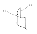
又、実施の形態1の発熱体ユニットにおいては、第1のガラス管1と第2のガラス管9の間に形成された前記所定の空隙空間(前記第2の内部空間の一部)には耐熱性に優れたフェライト系ステンレス鋼の板厚50μmの反射板16aが配置されている。この反射板16aの板面は発熱体2aの板幅面に対向し、かつ反射板16aの板面の長手方向は発熱体2aの長手方向に沿って対向し並列(図1においては平行)するように配置されている。さらに、反射板16aの板面に対し直交する方向に切断された場合の断面形状は、第2のガラス管9内に形成された前記所定の空隙空間に挿入可能となるように第1のガラス管1の外側壁面あるいは第2のガラス管9内側壁面に沿って湾曲(すなわち、第2のガラス管9内側壁面方向に突出)した湾曲形状となっている。その結果、反射板16aは熱輻射の指向性が高くなるとともに、反射板16aの汚染を防ぎ、高い輻射効率を維持することができる。   In the heating element unit according to the first embodiment, the predetermined gap space (a part of the second internal space) formed between the first glass tube 1 and the second glass tube 9 is not provided. A reflecting plate 16a made of ferritic stainless steel having a heat resistance and having a thickness of 50 μm is disposed. The plate surface of the reflecting plate 16a faces the plate width surface of the heating element 2a, and the longitudinal direction of the reflecting plate 16a faces the longitudinal direction of the heating member 2a and is parallel (parallel in FIG. 1). Is arranged. Furthermore, the cross-sectional shape when cut in the direction orthogonal to the plate surface of the reflecting plate 16a is such that the first glass can be inserted into the predetermined gap space formed in the second glass tube 9. The curved shape is curved along the outer wall surface of the tube 1 or the inner wall surface of the second glass tube 9 (that is, protruding toward the inner wall surface of the second glass tube 9). As a result, the reflecting plate 16a has high directivity of heat radiation, can prevent the reflecting plate 16a from being contaminated, and can maintain high radiation efficiency.

さらに、反射板16aは少なくとも一部に弾性部17(図4参照)が設けられることにより反射用部材16が構成されることとなる。本実施の形態1の発熱体ユニットのように、反射板16aとして板厚50μmの薄板を使用した場合には発熱体2aの輻射熱により昇温(例えば、約700℃)した反射板16aは熱膨張し、反射板16aに歪が発生し、シワ、ねじれや、及び破損が発生する恐れがある。反射板16aの少なくとも一部に弾性部17を設けることにより反射板16aの熱膨張を吸収して反射板16aの歪を生じなくできるので、反射板16aは所定の品質を保持した状態で寿命を長く保つことができる。   Furthermore, the reflecting member 16 is configured by providing the reflecting plate 16a with at least a portion of the elastic portion 17 (see FIG. 4). When a thin plate having a thickness of 50 μm is used as the reflecting plate 16a as in the heating unit of the first embodiment, the reflecting plate 16a heated by the radiant heat of the heating element 2a (for example, about 700 ° C.) is thermally expanded. In addition, the reflector 16a may be distorted, causing wrinkles, twists, and breakage. By providing the elastic portion 17 on at least a part of the reflecting plate 16a, it is possible to absorb the thermal expansion of the reflecting plate 16a and prevent the reflecting plate 16a from being distorted. Therefore, the reflecting plate 16a has a predetermined life while maintaining a predetermined quality. Can keep long.

ここで反射板16aの材料としてフェライト系ステンレス鋼を用いたが高温度で変色し難く反射率の高い金属、例えばニッケル(Ni)、ニクロム、金、白金、クロム合金等の材料を用いて構成しても同様の効果を得ることができる。又、発熱体ユニットが構成的に高温度にならない場合は、アルミニウム(AL)、アルミ合金、一般ステンレス鋼(例えば、オーステナイト)、銅合金等を用いても同様の効果が得られることは言うまでもない。   Here, ferritic stainless steel is used as the material of the reflecting plate 16a. However, the reflecting plate 16a is made of a material that is difficult to discolor at high temperatures and has a high reflectance, such as nickel (Ni), nichrome, gold, platinum, and a chromium alloy. However, the same effect can be obtained. Needless to say, if the heating unit is not structurally heated, the same effect can be obtained by using aluminum (AL), aluminum alloy, general stainless steel (for example, austenite), copper alloy, or the like. .

保持部材10の係合孔11の側壁には切欠状の反射板係合部18(図2参照)が形成されており、第1のガラス管1の外側壁面に対向する反射板係合部18の側壁面は、反射板16aの湾曲した板面を位置規制可能に対向するように湾曲形状した湾曲面で形成されている。又、その反射板係合部18には前記空隙空間に配置された反射板16aの長手方向に位置した端部が係合され、かつ前記反射板16aの端部が反射板16aの長手方向に貫通されるように形成されるとともに、発熱体2a及び第1のガラス管1の長手方向中心軸を回動中心として反射板16aが周方向に回動しないように、反射板16aの長手方向に沿って板厚部が形成される対向する一対の板厚側面にそれぞれ当接して位置規制する回動阻止部19が形成されている。   A notch-like reflecting plate engaging portion 18 (see FIG. 2) is formed on the side wall of the engaging hole 11 of the holding member 10, and the reflecting plate engaging portion 18 facing the outer wall surface of the first glass tube 1. The side wall surface is formed of a curved surface that is curved so as to oppose the curved plate surface of the reflecting plate 16a so as to be position-controllable. Further, the reflection plate engaging portion 18 is engaged with an end portion located in the longitudinal direction of the reflection plate 16a disposed in the gap space, and the end portion of the reflection plate 16a is extended in the longitudinal direction of the reflection plate 16a. The reflective plate 16a is formed in a longitudinal direction of the reflective plate 16a so that the reflective plate 16a does not rotate in the circumferential direction with the longitudinal axis of the heating element 2a and the first glass tube 1 as a rotational center. A rotation preventing portion 19 is formed that abuts against a pair of opposing plate thickness side surfaces along which the plate thickness portion is formed to regulate the position.

又、反射板16aの長手方向に位置する端部に設けられた外側方(発熱体2aから見て第2のガラス管9の方向)に突出する突起20(図3参照)は、反射板係合部18より外側方の位置で、かつ第2の保持用凹部15の底面(図1においては、第1のガラス管1の中心軸に直交するように位置する面)に形成された位置規制凹部21(図2参照)に係止され、反射板16aの長手方向の移動ができないように位置規制されることとなる。尚、突起20が位置規制凹部21から脱落して位置規制が解除されないように、前述した接着剤14を第2の隙間空間に塗布する際に突起20と位置規制凹部21とが接着剤14により接着され固定される。その結果、反射板16aあるいは反射用部材16は、保持部材10によって第1のガラス管1及び前記発熱体2aの長手方向を回動中心とした前記周方向の回動と反射板16aの長手方向への移動が規制されることとなる。   Further, a protrusion 20 (see FIG. 3) protruding outward (in the direction of the second glass tube 9 when viewed from the heating element 2a) provided at an end portion located in the longitudinal direction of the reflecting plate 16a is provided on the reflecting plate. A position restriction formed on the outer side of the joining portion 18 and on the bottom surface of the second holding recess 15 (in FIG. 1, the surface positioned so as to be orthogonal to the central axis of the first glass tube 1). The position is restricted so that the reflection plate 16a cannot be moved in the longitudinal direction by being locked by the recess 21 (see FIG. 2). In order to prevent the protrusion 20 from falling off the position restricting recess 21 and releasing the position restriction, the protrusion 20 and the position restricting recess 21 are formed by the adhesive 14 when the adhesive 14 is applied to the second gap space. Glued and fixed. As a result, the reflecting plate 16a or the reflecting member 16 is rotated by the holding member 10 in the circumferential direction around the longitudinal direction of the first glass tube 1 and the heating element 2a and the longitudinal direction of the reflecting plate 16a. Movement to is restricted.

したがって、本実施の形態1の発熱体ユニットにおいては、反射板16aを発熱体2aに対して所定の位置に配置されるための位置規制部として、突起20と位置規制凹部21が反射板16aの長手方向の位置規制を行い、かつ回動阻止部19が反射板16aの回動規制を行うとともに、反射板係合部18と第1のガラス管1が発熱体2aの離反距離を規制することとなる。尚、反射板16aを発熱体2aに対して所定の位置に配置されるための位置規制部は、前述した構成に限るものではなく、第1のガラス管1、第2のガラス管9及び保持部材10の少なくとも1つを利用して形成されれば良いことはいうまでもない。例えば、第1のガラス管1や第2のガラス管9を加熱して凸部を形成し、反射板16aと凸部を係合あるいは当接させることにより反射板16aの位置移動を規制することもできる。   Therefore, in the heat generating unit of the first embodiment, the protrusion 20 and the position restricting recess 21 of the reflecting plate 16a serve as a position restricting portion for disposing the reflecting plate 16a at a predetermined position with respect to the heat generating member 2a. The position restriction in the longitudinal direction is performed, the rotation prevention unit 19 regulates the rotation of the reflection plate 16a, and the reflection plate engagement unit 18 and the first glass tube 1 regulate the separation distance of the heating element 2a. It becomes. The position restricting portion for disposing the reflecting plate 16a at a predetermined position with respect to the heating element 2a is not limited to the configuration described above, and the first glass tube 1, the second glass tube 9, and the holding member. Needless to say, it may be formed using at least one of the members 10. For example, the first glass tube 1 or the second glass tube 9 is heated to form a convex portion, and the position movement of the reflective plate 16a is regulated by engaging or abutting the reflective plate 16a with the convex portion. You can also.

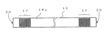
図4は実施の形態1における反射用部材16の一例を示すものであり、図面上では平面展開している。この反射用部材16の主要部である反射板16aはフェライト系ステンレス鋼で形成されており、その寸法は、例えば、長さ(長手方向)400mm、板幅(長手方向に直交する方向)15mm、厚み50μmであり、実際の反射板16aの板厚方向に切断された場合の断面形状は、第1のガラス管1の外側壁面あるいは第2のガラス管9内側壁面第2のガラス管9内に形成された前記所定の空隙空間に挿入可能な形状、例えば第1のガラス管1の外側壁面あるいは第2のガラス管9内側壁面に沿って湾曲した湾曲形状となっている。前記反射板16aの長手方向にある両端部には、上記で説明した保持部材10内面に固定するための突起20が形成され、また前記突起20の近傍には弾性部17となる切込み部が形成されている。   FIG. 4 shows an example of the reflecting member 16 in the first embodiment, which is developed in a plane on the drawing. The reflecting plate 16a which is the main part of the reflecting member 16 is made of ferritic stainless steel, and its dimensions are, for example, length (longitudinal direction) 400 mm, plate width (direction perpendicular to the longitudinal direction) 15 mm, The cross-sectional shape when the thickness is 50 μm and the actual reflector 16a is cut in the thickness direction is within the second glass tube 9 on the outer wall surface of the first glass tube 1 or the inner wall surface of the second glass tube 9. The shape can be inserted into the predetermined gap space formed, for example, a curved shape curved along the outer wall surface of the first glass tube 1 or the inner wall surface of the second glass tube 9. Protrusions 20 for fixing to the inner surface of the holding member 10 described above are formed at both ends in the longitudinal direction of the reflecting plate 16a, and incisions to be elastic portions 17 are formed in the vicinity of the protrusions 20. Has been.

この切込み部は第1の切り込み線と第2の切り込み線との組み合わせで構成されている。第1の切り込み線は、反射板16aの一対の板幅側辺(板幅面の長手方向に沿って形成される対向する1対の側辺)それぞれを起点として前記板幅側辺に交差(図4に示す例では直交)する方向に向けて対向する他の板幅側辺近傍まで切り込んで形成されるとともに、一方の板幅側辺に形成された第1の切り込み線と他方の板幅側辺に形成された第1の切り込み線とは交互すなわち千鳥状に配置され、かつそれらは前記長手方向に沿って所定の間隔を有して対向(図4においては平行)しながら複数配置され群を形成している。   This incision part is constituted by a combination of a first incision line and a second incision line. The first score line intersects the plate width side starting from each of a pair of plate width side sides (a pair of opposing sides formed along the longitudinal direction of the plate width surface) of the reflecting plate 16a (see FIG. In the example shown in Fig. 4, the first cut line formed on one side of the plate width side and the other side of the plate width side are formed by cutting to the vicinity of the other side of the plate width side facing in the direction that is orthogonal) The first cut lines formed on the sides are alternately arranged in a staggered manner, and a plurality of them are arranged while facing each other (parallel in FIG. 4) with a predetermined interval along the longitudinal direction. Is forming.

さらに、第2の切り込み線は、少なくとも反射板16aの一対の板幅側辺近傍を除いた反射板16aの板幅中央に第1の切り込み線に対向(図4においては平行)するように切り込んで形成されるとともに、反射板16aの一方の板幅側辺に形成された第1の切り込み線と他方の板幅側辺に形成された第1の切り込み線の中間(すなわち前記所定の間隔の中間)、及び、長手方向において複数の第1の切り込み線の群両端にそれぞれ位置する第1の切り込み線の外側にそれぞれ配置される。   Further, the second cut line is cut so as to face the first cut line (parallel in FIG. 4) at the center of the width of the reflecting plate 16a excluding at least the vicinity of the pair of plate width sides of the reflecting plate 16a. Between the first cut line formed on one plate width side of the reflecting plate 16a and the first cut line formed on the other plate width side (that is, at the predetermined interval). (Intermediate) and the first cut lines located at both ends of the group of the first cut lines in the longitudinal direction, respectively.

この反射板16aの材料がフェライト系ステンレス鋼であり、前述したように、寸法が長さ400mm、板幅15mm、厚み50μmである場合には、800℃で長手方向に約5mm程も熱膨張するため、取付け方法としては、予め反射板16aの長手方向に張力を加えるように前記弾性部17となる切込み部を変形せしめた状態(すなわち、2箇所に設けた弾性部17の全体の弾性変形で長手方向に約5mm伸ばした状態)で保持部材10に固定する。そうすることにより、発熱体2aからの熱輻射によって反射板16aが熱膨張したとしても、その熱膨張は反射板16aに張力を加えていた弾性部17となる切込み部への張力を減じて切込み部の変形が軽減される方向で吸収されることとなるので、反射板16aがシワや破損が生じることなく高寿命の発熱体ユニットが実現できる。尚、前述した弾性部17は、図4においては反射板16a両端部近傍に形成した例で説明したが、必ずしも両端部近傍である必要はなく、又、個数についても、反射板16aの形状、材質等により適宜設定することが可能であり限定するものではない。   When the material of the reflecting plate 16a is ferritic stainless steel and the dimensions are 400 mm in length, 15 mm in plate width, and 50 μm in thickness as described above, it thermally expands by about 5 mm in the longitudinal direction at 800 ° C. For this reason, as a mounting method, a state in which the cut portion that becomes the elastic portion 17 is deformed in advance so as to apply tension in the longitudinal direction of the reflecting plate 16a (that is, by the entire elastic deformation of the elastic portion 17 provided in two places). It is fixed to the holding member 10 in a state of being extended by about 5 mm in the longitudinal direction. By doing so, even if the reflector 16a thermally expands due to thermal radiation from the heating element 2a, the thermal expansion reduces the tension to the cut portion that becomes the elastic portion 17 that applied tension to the reflector 16a. Therefore, the heat generating unit with a long life can be realized without causing the reflector 16a to be wrinkled or damaged. In addition, although the elastic part 17 mentioned above demonstrated in the example formed in the reflector 16a both ends vicinity in FIG. 4, it does not necessarily need to be near both ends, and also about the number, the shape of the reflector 16a, It can be appropriately set depending on the material and the like, and is not limited.

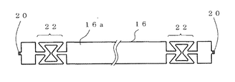
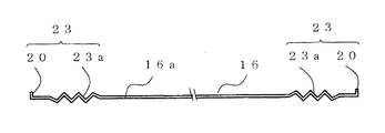
実施の形態1の発熱体ユニットにおいては、図4に示した反射用部材16の弾性部17は切込み部にて形成した例で説明したが、弾性部17の構成としては種々の形状・構成があり、その例を図5から図7に示す。   In the heat generating unit of the first embodiment, the example in which the elastic portion 17 of the reflecting member 16 shown in FIG. 4 is formed by a cut portion has been described. However, the elastic portion 17 has various shapes and configurations. An example is shown in FIGS.

図5において、図5は図4と同様に図面上では平面展開されている。前記弾性部17に代えて用いられた反射用部材16の弾性部22は、反射板16aの両端部側の位置に反射板16aの対向する一対の板幅側辺に切欠き部をそれぞれ形成することにより、反射板16aの長手方向の中心線上に細幅の帯体を形成するとともに、その帯体の長手方向中間部には、前記長手方向に沿って配置された互いに対向する一対の長手方向枠辺と、前記長手方向に直交するように配置された互いに対向する一対の板幅方向枠辺とにより構成された中央に孔部を有した四辺形の枠体が形成されたものである。さらに、前記枠体の一対の板幅方向枠辺はそれぞれ孔部方向に突出するようにくの字形状に形成されることにより、前記枠体は弾性変形可能となり弾性部22としての役割を果たすように構成したものである。   In FIG. 5, FIG. 5 is developed in a plan view on the drawing similarly to FIG. 4. The elastic portions 22 of the reflecting member 16 used in place of the elastic portions 17 are formed with notches on a pair of opposite sides of the reflecting plate 16a at positions on both ends of the reflecting plate 16a. Thus, a narrow strip is formed on the longitudinal center line of the reflecting plate 16a, and a pair of longitudinal directions disposed along the longitudinal direction at the middle portion in the longitudinal direction of the strip are opposed to each other. A quadrilateral frame having a hole in the center is formed by a frame side and a pair of frame width direction frame sides arranged opposite to each other so as to be orthogonal to the longitudinal direction. Further, the pair of plate width direction frame sides of the frame body are formed in a U-shape so as to protrude in the direction of the hole, respectively, so that the frame body can be elastically deformed and serve as the elastic portion 22. It is comprised as follows.

図6及び図7において、図6は図4と同様に図面上では平面展開されており、図7は前記平面展開された図6に対する正面図である。図6及び図7に示す反射用部材16の弾性部23は前記弾性部17に相当するものであり、反射板16aの両端部にそれぞれは配置されたものである。弾性部23は反射板16aの板幅を小幅な板体に形成し、その小幅の板体の中央側を波状、鋸歯状あるいは蛇腹状等に屈曲せしめて前記加えられる張力に応じて伸縮自在な屈曲部23aを形成したものである。さらに、屈曲部23aの外方に位置する遊端部には突起20が弾性部23の一部として形成されている。尚、図6に示す弾性部23あるいは屈曲部23aの板幅寸法は適度な伸縮自在性と反射用部材16の一部としての強度とを考慮しながら反射板16aの板幅寸法より小さく設定しているが、反射板16aの材質、発熱体ユニットの構成等の条件によって任意の寸法・形状にしてもよいことはいうまでもない。   6 and 7, FIG. 6 is developed in a plan view in the same manner as FIG. 4, and FIG. 7 is a front view with respect to FIG. The elastic part 23 of the reflecting member 16 shown in FIGS. 6 and 7 corresponds to the elastic part 17 and is arranged at both ends of the reflecting plate 16a. The elastic portion 23 is formed in a narrow plate body with the reflector plate 16a having a small width, and the central side of the narrow plate body is bent into a wave shape, a sawtooth shape, a bellows shape, or the like, and can be expanded and contracted in accordance with the applied tension. A bent portion 23a is formed. Further, a protrusion 20 is formed as a part of the elastic portion 23 at the free end located outside the bent portion 23a. The plate width dimension of the elastic portion 23 or the bent portion 23a shown in FIG. 6 is set smaller than the plate width size of the reflection plate 16a in consideration of appropriate stretchability and strength as a part of the reflection member 16. However, it goes without saying that the size and shape may be arbitrarily set depending on conditions such as the material of the reflecting plate 16a and the configuration of the heating element unit.

以上説明した弾性部17、弾性部22及び弾性部23は、上述した形状、材料、個数及び位置等に拘束されるのではなく、反射板16aの機能を阻害することなく反射用部材16の長手方向に弾性機能を得るものであれば、例えば反射用部材16の両端にそれぞれ設けず片端のみに設けることでもよいことはいうまでもない。   The elastic part 17, the elastic part 22, and the elastic part 23 described above are not restricted by the shape, material, number, position, etc. described above, but the length of the reflecting member 16 without impairing the function of the reflecting plate 16a. Of course, as long as an elastic function is obtained in the direction, for example, the reflecting member 16 may be provided only at one end without being provided at both ends.

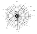
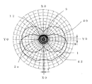
次に、図8乃至図9を用いて本発明に係る実施の形態1の発熱体ユニットの輻射強度の状態を説明する。図8は発熱体2a板幅面と反射板16aの板面が互いに平行的に対向するような関係に配置された状態において、発熱体2aと反射板16aの長手方向に対して直交する断平面上に示される輻射強度曲線図、図9は発熱体2a板幅面と反射板16aの板面が互いに直交するような関係に配置された状態において、発熱体2aと反射板16aの長手方向に対して直交する断平面上に示される輻射強度曲線図である。   Next, the state of radiation intensity of the heating element unit according to the first embodiment of the present invention will be described with reference to FIGS. FIG. 8 is a cross-sectional view orthogonal to the longitudinal direction of the heating element 2a and the reflecting plate 16a in a state where the heating element 2a plate width surface and the reflecting plate 16a face each other in parallel. FIG. 9 shows the radiation intensity curve shown in FIG. 9 with respect to the longitudinal direction of the heating element 2a and the reflecting plate 16a in the state where the heating element 2a plate width surface and the reflecting plate 16a are arranged so as to be orthogonal to each other. It is a radiation intensity curve figure shown on the orthogonal plane which intersects perpendicularly.

図8において、発熱体2aの板幅面すなわち板幅W方向(X0−X0)に対し反射板16aの板面が平行的に対向するような関係に配置されており、発熱体2aと反射板16aの長手方向に対して直交する断平面上に輻射強度曲線が示されている。図8においては発熱体2aの板厚Tを1、板幅Wを5としている。尚、発熱体2aの板幅Tに対する板幅Wを5倍以上とすることで発熱体2aの板幅方向の輻射強度に指向性を持たすことができる。   In FIG. 8, the heat generating element 2a and the reflecting plate 16a are arranged in such a relationship that the plate surface of the reflecting plate 16a faces the plate width surface of the heating element 2a, that is, the plate width W direction (X0-X0) in parallel. A radiation intensity curve is shown on a cross-sectional plane orthogonal to the longitudinal direction of. In FIG. 8, the plate thickness T of the heating element 2a is 1 and the plate width W is 5. In addition, directivity can be given to the radiation intensity of the plate | board width direction of the heat generating body 2a by making the plate width W with respect to the plate width T of the heat generating body 2a 5 times or more.

輻射強度曲線40は反射板16aが無い場合の輻射強度曲線を示すものであり、発熱体2aの板厚T方向(Y0−YO方向)において双方向、すなわち図において熱体2aの板幅面に直交する方向で、発熱体2aを起点に右方向と発熱体2aを起点に左方向の両方向に指向性を有する輻射強度曲線を示している。他方、輻射強度曲線41は反射板16aを配設した場合の輻射強度曲線を示すものであり、発熱体2aの板厚T方向(Y0−YO方向)の一方向で、かつ発熱体2aを起点に反射板16aが配置されていない前記右方向に指向性を有する輻射強度曲線を示している。輻射強度曲線40と輻射強度曲線41を比較すると、発熱体2aから反射板16aが配置されていない前記右方向への輻射は、反射板16aの無い場合と比較して指向性が20〜30%向上することが可能となることがわかる。   The radiation intensity curve 40 shows a radiation intensity curve in the absence of the reflecting plate 16a, and is bidirectional in the plate thickness T direction (Y0-YO direction) of the heating element 2a, that is, orthogonal to the plate width surface of the heating element 2a in the figure. The radiation intensity curve having directivity in both the right direction starting from the heating element 2a and the left direction starting from the heating element 2a is shown. On the other hand, the radiation intensity curve 41 shows a radiation intensity curve when the reflecting plate 16a is disposed, and is one direction of the thickness T direction (Y0-YO direction) of the heating element 2a and starts from the heating element 2a. The radiation intensity curve which has directivity in the said right direction where the reflecting plate 16a is not arrange | positioned is shown. Comparing the radiation intensity curve 40 and the radiation intensity curve 41, the radiation in the right direction from the heating element 2a where the reflecting plate 16a is not disposed has a directivity of 20 to 30% as compared with the case without the reflecting plate 16a. It can be seen that it can be improved.

図9は、反射板16aと発熱体2aの位置関係は図8に示す実施例とは異なり、発熱体2aの板幅W方向(X0−X0)に対し反射板16aの板面が直交する方向(Y0−Y0)に配置されるように、発熱体2aの板厚面と反射板16aの板面(図において、発熱体2aの上方向に位置する)とが対向して配置されており、発熱体2aと反射板16aの長手方向に対して直交する断平面上に輻射強度曲線が示されている。尚、発熱体2aの板厚Tと板幅Wの割合は図8に示す実施例と同様である。   In FIG. 9, the positional relationship between the reflecting plate 16a and the heating element 2a is different from the embodiment shown in FIG. 8, and the plate surface of the reflecting plate 16a is perpendicular to the plate width W direction (X0-X0) of the heating element 2a. As shown in (Y0-Y0), the plate thickness surface of the heating element 2a and the plate surface of the reflecting plate 16a (located in the upper direction of the heating element 2a in the figure) are arranged to face each other. A radiation intensity curve is shown on a section plane orthogonal to the longitudinal direction of the heating element 2a and the reflecting plate 16a. The ratio of the plate thickness T and the plate width W of the heating element 2a is the same as that of the embodiment shown in FIG.

図9において、反射板16aが無い場合を示す輻射強度曲線40は図8に示すと同様の曲線を示す。他方、反射板16aを配設した場合は、図8とは異なり発熱体2aの板厚T方向(Y0−YO方向)への輻射が反射板16aに反射される発熱体2aの板幅W方向(X0−X0)の一方向、かつ発熱体2aを起点に反射板16aが配置されていない図において下方向に幅広いく輻射される輻射強度曲線42となる。   In FIG. 9, the radiation intensity curve 40 showing the case where there is no reflecting plate 16a is the same curve as shown in FIG. On the other hand, when the reflecting plate 16a is provided, unlike in FIG. 8, the radiation in the plate thickness T direction (Y0-YO direction) of the heating element 2a is reflected by the reflecting plate 16a in the plate width W direction. A radiation intensity curve 42 is radiated in a wide range downward in one direction of (X0-X0) and in the drawing in which the reflecting plate 16a is not disposed starting from the heating element 2a.

したがって、局部的な輻射強度を必要とする場合においては、図8に示すように発熱体2aの板幅面に対し反射板16aの板面が平行的に対向するような関係に反射板16aを配置し、幅広い輻射強度を必要とする場合においては、図9に示すように発熱体2aの板幅面に対し反射板16aの板面が直交するように、発熱体2aの板厚面と反射板16aの板面とが対向する関係に反射板16aを配置することができるので、用途に応じ選択することが可能となる。   Therefore, when local radiation intensity is required, the reflector 16a is arranged in such a relationship that the plate surface of the reflector 16a faces the plate width surface of the heating element 2a in parallel as shown in FIG. When a wide radiant intensity is required, the plate thickness surface of the heating element 2a and the reflecting plate 16a are arranged so that the plate surface of the reflecting plate 16a is orthogonal to the plate width surface of the heating element 2a as shown in FIG. Since the reflecting plate 16a can be arranged in a relationship facing the plate surface, it can be selected according to the application.

(実施の形態2)
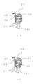
本発明に係る実施の形態2の発熱体ユニットについて図10乃至図18を用いて説明する。図10は実施の形態2の発熱体ユニットの構造を示す正面図、図11は同発熱体ユニットのY−Y断面における接着剤を省略した場合の断側面図、図12は同発熱体ユニットにおける反射板とコイル部とからなる反射用部材を示す切欠斜視図、図13は同反射用部材を示す平面図、図14は同反射用部材を示す正面図、図15は同発熱体ユニットにおける反射用部材の異なる例を示す平面図、図16は同反射用部材を示す正面図、図17は同発熱体ユニットにおける反射用部材の他の異なる例を示す平面図、図18は同反射用部材を示す正面図である。
(Embodiment 2)
A heating element unit according to Embodiment 2 of the present invention will be described with reference to FIGS. FIG. 10 is a front view showing the structure of the heating element unit according to the second embodiment, FIG. 11 is a sectional side view when the adhesive in the YY section of the heating element unit is omitted, and FIG. FIG. 13 is a plan view showing the reflecting member, FIG. 14 is a front view showing the reflecting member, and FIG. 15 is a reflection in the heating element unit. FIG. 16 is a front view showing the reflection member, FIG. 17 is a plan view showing another example of the reflection member in the heating element unit, and FIG. 18 is the reflection member. FIG.

先ず、図10乃至図14を用いて実施の形態2の発熱体ユニットを説明する。実施の形態2の説明及び図面において、前述の実施の形態1の発熱体ユニットと異なる構成は、反射板の一部を加工することにより形成された弾性体が反射板とは別体の部品で構成され、その別体の部品が保持部材に保持されることにより反射板が保持されている点である。尚、実施の形態2の説明及び図面において、前述の実施の形態1の発熱体ユニットと同じ機能、構成を有するものには同じ符号を付し、その説明を省略する。   First, the heating element unit according to the second embodiment will be described with reference to FIGS. In the description and drawings of the second embodiment, the configuration different from the heating element unit of the first embodiment is that the elastic body formed by processing a part of the reflector is a separate component from the reflector. The reflector is hold | maintained because it is comprised and the separate component is hold | maintained at a holding member. In the description and drawings of the second embodiment, components having the same functions and configurations as those of the heat generating unit of the first embodiment are denoted by the same reference numerals, and description thereof is omitted.

図10において、実施の形態2の発熱体ユニットにおける反射板24aは材料として、例えば、板厚50μmの耐熱性に優れたフェライト系ステンレス鋼を用いている。使用できる他の材料としては、高温度で変色し難く反射率の高い金属、例えばニッケル(Ni)、ニクロム、金、白金、クロム合金等の材料を用いて構成しても同様の効果を得ることができる。又、発熱体ユニットが構成的に高温度にならない場合は、アルミニウム(AL)、アルミ合金、一般ステンレス鋼(例えば、オーステナイト)、銅合金等を用いても同様の効果が得られることは言うまでもない。   In FIG. 10, the reflecting plate 24a in the heating element unit of Embodiment 2 is made of, for example, ferritic stainless steel having a plate thickness of 50 μm and excellent heat resistance. As other materials that can be used, the same effect can be obtained even if it is made of a material that is difficult to discolor at high temperatures and has a high reflectance, such as nickel (Ni), nichrome, gold, platinum, and a chromium alloy. Can do. Needless to say, if the heating unit is not structurally heated, the same effect can be obtained by using aluminum (AL), aluminum alloy, general stainless steel (for example, austenite), copper alloy, or the like. .

実施の形態2の発熱体ユニットにおける反射板24aは、実施の形態1の発熱体ユニットにおける反射板16aと同様に、第1のガラス管1と第2のガラス管9の間に形成された前記所定の空隙空間(前記第2の内部空間の一部)に配置されている。この反射板24aの板面は発熱体2aの板幅面に対向し、かつ反射板24aの板面の長手方向は発熱体2aの長手方向中心軸方向に沿って対向(図10においては平行)するように配置されている。さらに、反射板24aの板厚方向に切断された場合の切断断面形状(すなわち長手方向より見た断面形状)は、第2のガラス管9内に形成された前記所定の空隙空間に挿入可能となるように第1のガラス管1の外側壁面あるいは第2のガラス管9内側壁面に沿って湾曲(すなわち、第2のガラス管9内側壁面方向に突出)した湾曲形状となっている。又、反射板24aの長手方向の長さ及び板幅は少なくとも発熱体2aからの輻射される熱が反射板24aの前方(第1のガラス管1、第2のガラス管9、あるいは発熱体構成部2の方向)へ反射されるように設定されている。その結果、反射板24aは熱輻射の指向性が高くなるとともに、反射板24aの汚染を防ぎ、高い輻射効率を維持することができる。   The reflector 24a in the heating element unit of the second embodiment is formed between the first glass tube 1 and the second glass tube 9 in the same manner as the reflector 16a in the heating element unit of the first embodiment. It is arranged in a predetermined gap space (a part of the second internal space). The plate surface of the reflecting plate 24a is opposed to the plate width surface of the heating element 2a, and the longitudinal direction of the reflecting plate 24a is opposed along the central axis direction of the heating element 2a (parallel in FIG. 10). Are arranged as follows. Furthermore, the cut cross-sectional shape (that is, the cross-sectional shape seen from the longitudinal direction) when cut in the thickness direction of the reflecting plate 24a can be inserted into the predetermined gap space formed in the second glass tube 9. The curved shape is curved along the outer wall surface of the first glass tube 1 or the inner wall surface of the second glass tube 9 (that is, protrudes toward the inner wall surface of the second glass tube 9). The length and width of the reflecting plate 24a in the longitudinal direction are such that at least the heat radiated from the heating element 2a is in front of the reflecting plate 24a (the first glass tube 1, the second glass tube 9, or the heating element configuration). It is set to be reflected in the direction of part 2). As a result, the reflecting plate 24a has high directivity of heat radiation, prevents contamination of the reflecting plate 24a, and maintains high radiation efficiency.

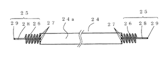
図13及び図14に示す反射用部材24は、弾性部25が反射板24aの両端部にそれぞれ位置するように設けられており、その内部には内径側空間を有するようにニクロム線等からなる線材を巻いて形成した弾性変形可能なコイル部26で構成されたものである。図13及び図14においては、反射板24aの寸法は板幅15mm、板厚50μm、長さ350mmであり、弾性部25の主要部の1つであるコイル部26の寸法は、長さ25mmであり、線材径φ0.4の線材を5ターン巻いている。この弾性部25と反射板24aとの取付け構造を図12の(a)を用いて説明すると、前記コイル部26の一端部は反射板24aの両端部にそれぞれ取付けられている。すなわち、反射板の一端部に位置する湾曲形状の板面が前記コイル部26の一端部に位置するコイル形状に形成された湾曲(曲線)形状の線材を覆った状態で当接しており、複数(図12の(a)においては3箇所)の溶接部27にて溶接することにより、反射板24aの一端部と前記コイル部26の一端部とが固定されるように保持され、反射用部材24が構成されている。尚、図12の(a)に示す実施の形態2の発熱体ユニットにおいては、溶接部27を3箇所としたが、反射板24aを固定できる強度を得ることが出来るのであれば数にこだわらないことはいうでもない。   The reflecting member 24 shown in FIGS. 13 and 14 is provided so that the elastic portions 25 are located at both ends of the reflecting plate 24a, respectively, and is made of a nichrome wire or the like so as to have an inner diameter side space therein. It is composed of an elastically deformable coil portion 26 formed by winding a wire. In FIG. 13 and FIG. 14, the reflecting plate 24 a has a plate width of 15 mm, a plate thickness of 50 μm, and a length of 350 mm, and the coil portion 26 that is one of the main parts of the elastic portion 25 has a length of 25 mm. Yes, a wire with a wire diameter of φ0.4 is wound for 5 turns. The attachment structure of the elastic portion 25 and the reflector 24a will be described with reference to FIG. 12A. One end of the coil portion 26 is attached to both ends of the reflector 24a. That is, the curved plate surface located at one end of the reflecting plate is in contact with the curved (curved) shaped wire formed in the coil shape located at one end of the coil portion 26, and is in contact with each other. By welding at the welded portions 27 (three places in FIG. 12A), one end of the reflector 24a and one end of the coil portion 26 are held so as to be fixed. 24 is configured. In addition, in the heating element unit of Embodiment 2 shown in FIG. 12A, the number of the welded portions 27 is three, but the number is not limited as long as the strength capable of fixing the reflecting plate 24a can be obtained. Not to mention.

又、前記コイル部26の他端部にはコイル外径と同位置の箇所よりコイル部26のスラスト軸方向に沿って対向するよう屈曲し、かつ反射板24aの端部面より離反する外方向に向かって延設されたコイル延端部28が形成されている。さらに、前記コイル延端部28の先端部はコイル部26の長手方向中心軸に対し直交する方向で、かつ前記長手方向中心軸より離反する方向に屈曲した屈曲部29が形成されている。   Further, the other end of the coil portion 26 is bent so as to be opposed along the thrust axis direction of the coil portion 26 from a position at the same position as the outer diameter of the coil, and is outwardly separated from the end surface of the reflecting plate 24a. A coil extended end portion 28 extending toward is formed. Further, a distal end portion of the coil extending end portion 28 is formed with a bent portion 29 that is bent in a direction orthogonal to the longitudinal central axis of the coil portion 26 and in a direction away from the longitudinal central axis.

又、上記弾性体25が保持される図10及び図11に示す実施の形態2の発熱体ユニットにおける保持部材30と図1及び図2に示す実施の形態1の発熱体ユニットにおける保持部材10との異なる点を説明すると、保持部材10に設けられている係合孔11の側壁に形成された反射板係合部18とその反射板係合部18に形成された回動阻止部19が不要となり、反射板係合部18に代えて切欠状のコイル延端係合部31が係合孔11の側壁に形成されている点である。このコイル延端係合部31は第2の保持用凹部15の底面に形成されている位置規制凹部21(図11参照)に連通している。   Further, the holding member 30 in the heating element unit of the second embodiment shown in FIGS. 10 and 11 where the elastic body 25 is held, and the holding member 10 in the heating element unit of the first embodiment shown in FIGS. In other words, the reflecting plate engaging portion 18 formed on the side wall of the engaging hole 11 provided in the holding member 10 and the rotation blocking portion 19 formed on the reflecting plate engaging portion 18 are unnecessary. Thus, instead of the reflector engaging portion 18, a notch-like coil extension end engaging portion 31 is formed on the side wall of the engaging hole 11. The coil extension end engaging portion 31 communicates with a position restricting recess 21 (see FIG. 11) formed on the bottom surface of the second holding recess 15.

以上説明した反射板24aに取り付けられた弾性部25のコイル部26は、保持部材30の係合孔11に保持されている。第1のガラス管1の端部側がコイル部26の内径側空間に貫通された状態で係合している。保持部材30の係合孔11の側壁面にはコイル延端係合部31が形成されており、そのコイル延端係合部31に弾性部25のコイル延端部28が挿入されて係合されている。コイル延端係合部31及び係合孔11を貫通せしめた屈曲部29はコイル延端係合部31より外側方の位置で、かつ第2の保持用凹部15の底面(図10においては、第1のガラス管1、第2のガラス管9、あるいは発熱体構成部2の長手方向中心軸に直交するように位置する面)に形成された位置規制凹部21に係合し係止される。   The coil portion 26 of the elastic portion 25 attached to the reflection plate 24 a described above is held in the engagement hole 11 of the holding member 30. The end side of the first glass tube 1 is engaged with the inner diameter side space of the coil portion 26. A coil extension end engagement portion 31 is formed on the side wall surface of the engagement hole 11 of the holding member 30, and the coil extension end portion 28 of the elastic portion 25 is inserted into the coil extension end engagement portion 31 to be engaged. Has been. The bent portion 29 penetrating the coil extension end engaging portion 31 and the engagement hole 11 is located on the outer side of the coil extension end engaging portion 31 and the bottom surface of the second holding recess 15 (in FIG. The first glass tube 1, the second glass tube 9, or a surface that is positioned perpendicular to the central axis in the longitudinal direction of the heating element component 2) is engaged and locked. .

又、前記位置規制凹部21に係止された屈曲部29は、第2のガラス管9内に被加熱物から飛散する汚染物質等の進入の恐れがある場合を想定して第2の保持用凹部15と第1のガラス管1との間に生じた第2の隙間空間に接着剤14が塗布される際に、接着剤14によって位置規制凹部21に接着されて固定保持されることとなり、反射板24aのスラスト軸方向の移動ができないように位置規制されることとなる。さらに、コイル部26の内径側空間に第1のガラス管1の端部が係合するととともに、保持部材28のコイル延端係合31にコイル延端部28が係合する、あるいは前記位置規制凹部21に屈曲部29が係合して係止されることになるので、反射板24a及び弾性部25は保持部材30によって第1のガラス管1及び前記発熱体2aの長手方方向中心軸を回動中心とした周方向の回動が規制されることとなる。   Further, the bent portion 29 locked to the position restricting recess 21 is used for the second holding in the case where there is a possibility that contaminants or the like scattered from the object to be heated enter the second glass tube 9. When the adhesive 14 is applied to the second gap space generated between the recess 15 and the first glass tube 1, the adhesive 14 adheres to the position restricting recess 21 and is fixed and held. The position of the reflector 24a is restricted so that it cannot be moved in the thrust axis direction. Further, the end portion of the first glass tube 1 is engaged with the inner diameter side space of the coil portion 26, and the coil extension end portion 28 is engaged with the coil extension end engagement 31 of the holding member 28, or the position restriction is performed. Since the bent portion 29 is engaged and locked with the concave portion 21, the reflecting plate 24a and the elastic portion 25 are caused to hold the central axis in the longitudinal direction of the first glass tube 1 and the heating element 2a by the holding member 30. The rotation in the circumferential direction around the rotation center is restricted.

したがって、本実施の形態2の発熱体ユニットにおいては、反射板24aが発熱体2aに対して所定の位置に配置されるための位置規制部として、屈曲部29と位置規制凹部21とはその係合により反射板24aの長手方向の位置規制を行い、屈曲部29と位置規制凹部21、あるいはコイル延端部28とコイル延端係合部31とは、その係合により反射板24aの回動規制を行い、コイル延端部28とコイル延端係合部31、あるいはコイル部26の内径側と第1のガラス管1とはその係合により反射板24aと発熱体2aとの離反距離を規制することとなる。尚、反射板24aが発熱体2aに対して所定の位置に配置されるための位置規制部は、前述した構成に限るものではなく、第1のガラス管1、第2のガラス管9及び保持部材30の少なくとも1つを利用して形成されれば良いことはいうまでも無い。例えば第1のガラス管1や第2のガラス管を加熱して凸部を形成し、凸部を係合あるいは当接させることにより反射板24aの位置移動を規制することもできる。   Therefore, in the heat generating unit of the second embodiment, the bent portion 29 and the position restricting concave portion 21 are related to the position restricting portion for arranging the reflector 24a at a predetermined position with respect to the heat generating member 2a. Accordingly, the position of the reflecting plate 24a is regulated in the longitudinal direction, and the bent portion 29 and the position regulating recess 21 or the coil extending end portion 28 and the coil extending end engaging portion 31 are rotated by the engagement of the reflecting plate 24a. The coil extending end portion 28 and the coil extending end engaging portion 31 or the inner diameter side of the coil portion 26 and the first glass tube 1 are engaged with each other so that the separation distance between the reflecting plate 24a and the heating element 2a is increased. It will be regulated. The position restricting portion for arranging the reflecting plate 24a at a predetermined position with respect to the heating element 2a is not limited to the configuration described above, and the first glass tube 1, the second glass tube 9, and the holding member. Needless to say, it may be formed using at least one of the members 30. For example, the first glass tube 1 or the second glass tube is heated to form a convex portion, and the positional movement of the reflecting plate 24a can be regulated by engaging or abutting the convex portion.

又、反射板24aを第1のガラス管1と第2のガラス管9との間に形成された所定の空隙空間内に配置するために保持部材30に保持された弾性部25のコイル部26は、常温状態では、外部より電力供給された発熱体2aの輻射熱により昇温して熱膨張した反射板24aの長さ変化が吸収できるように、反射板24aに張力を与えるように伸びた状態となっている。したがって、前述したように反射板24aの寸法が板幅15mm、板厚50μm、長さ350mmで構成され、かつ材料がフェライト系ステンレス鋼である場合には、反射板24aが800℃に昇温すれば反射板24aは長手方向に約4.5mm熱膨張するため、コイル部26は予めコイル部26の長手方向(反射板24aの長手方向と同じ方向)に張力が加えられて4.5mm伸ばした状態で保持部材30に固定する。その結果、発熱体2aからの熱輻射によって反射板16aが熱膨張して反射板24aの長さが変化したとしても、その熱膨張による反射板24aの長さ変化は反射板24aに張力を加えていた弾性部25となるコイル部26の伸び変形が軽減される方向で吸収されることとなるので、反射板16aがシワや破損が生じることなく高寿命の発熱体ユニットが実現できる。   In addition, the coil portion 26 of the elastic portion 25 held by the holding member 30 in order to arrange the reflecting plate 24a in a predetermined gap space formed between the first glass tube 1 and the second glass tube 9. In a normal temperature state, the reflector 24a is stretched so as to give a tension so as to absorb the change in length of the reflector 24a that has been heated and expanded by the radiant heat of the heating element 2a supplied with power from the outside. It has become. Therefore, as described above, when the reflector 24a has a plate width of 15 mm, a plate thickness of 50 μm, and a length of 350 mm, and the material is ferritic stainless steel, the reflector 24 a is heated to 800 ° C. For example, since the reflecting plate 24a thermally expands in the longitudinal direction by about 4.5 mm, the coil portion 26 is stretched 4.5 mm by applying a tension in the longitudinal direction of the coil portion 26 in advance (the same direction as the longitudinal direction of the reflecting plate 24a). It fixes to the holding member 30 in a state. As a result, even if the reflecting plate 16a is thermally expanded by heat radiation from the heating element 2a and the length of the reflecting plate 24a is changed, the change in the length of the reflecting plate 24a due to the thermal expansion applies tension to the reflecting plate 24a. Since the extension deformation of the coil portion 26 that becomes the elastic portion 25 is absorbed in a direction to be reduced, a long-life heating element unit can be realized without causing the reflector 16a to be wrinkled or damaged.

尚、前述した図10乃至図14を用いて説明した実施の形態2の発熱体ユニットの一例においては、反射板24aの両端部に弾性体25がそれぞれ設けられ場合を説明したが、必ずしも両端部近傍である必要はなく、個数についても、反射板24aの形状、材質等により適宜設定することが可能であり限定するものではない。   In the example of the heating element unit according to Embodiment 2 described with reference to FIGS. 10 to 14, the case where the elastic bodies 25 are provided at both ends of the reflector 24a has been described. There is no need to be in the vicinity, and the number can be appropriately set depending on the shape, material, etc. of the reflector 24a, and is not limited.

又、実施の形態2の発熱体ユニットを有した加熱装置あるいは前記発熱体ユニット自体の構成(例えば、フィルター付き)により第2のガラス管の第2の隙間空間内に被加熱物から飛散する汚染物質等の進入を防止できる構造となるのであれば、第1の隙間空間及び第2の隙間空間の何れかに接着剤14を塗布しない、あるいは塗布しても前記第2の内部空間を完全に封止しないことが選択できることはいうまでもない。さらに、第2の隙間空間に接着剤14が塗布されない場合には、接着剤14の塗布にて位置規制凹部21と屈曲部29とを保持するか否かは、位置規制凹部21と屈曲部29との保持構成、保持強度、及び保持の信頼性等を考慮して決定すればよいことである。   Further, the contamination scattered from the object to be heated in the second gap space of the second glass tube by the heating device having the heating element unit of the second embodiment or the configuration of the heating element unit itself (for example, with a filter). If the structure can prevent the entry of a substance or the like, the adhesive 14 is not applied to either the first gap space or the second gap space, or the second inner space is completely removed even if applied. Needless to say, it can be selected not to seal. Further, when the adhesive 14 is not applied to the second gap space, whether or not the position restricting recess 21 and the bent portion 29 are held by the application of the adhesive 14 depends on whether the position restricting recess 21 and the bent portion 29 are held. It may be determined in consideration of the holding configuration, holding strength, holding reliability, and the like.

実施の形態2の発熱体ユニットにおいては、反射用部材24は図12(a)に示したように反射板24aの一端部とコイル部26の一端部に位置するコイル形状に形成された湾曲形状の線材との保持構成として溶接のみにより固定した例を用いて説明したが、反射板24aとコイル部26の配置関係が維持できるのであれば公知の保持構造でもよく、又、それらと溶接の併用により保持を行ってもよい。例えば、図12(b)に示す反射用部材24のように、湾曲した反射板24aの端部において反射板24aの板面に対し湾曲中心側(発熱体2aが位置する発熱体ユニットの内径側)に立設するように折り曲がった規制用係止片32により反射板24aの裏面側に配置するコイル部26の一端部の位置決めを行いながら溶接部27にて溶接するものである。   In the heating element unit according to the second embodiment, the reflecting member 24 has a curved shape formed in a coil shape located at one end of the reflecting plate 24a and one end of the coil portion 26 as shown in FIG. However, as long as the arrangement relationship between the reflecting plate 24a and the coil portion 26 can be maintained, a known holding structure may be used, or a combination of them and welding may be used. You may hold | maintain by. For example, like the reflecting member 24 shown in FIG. 12B, the curved center side with respect to the plate surface of the reflecting plate 24a at the end of the curved reflecting plate 24a (the inner diameter side of the heating element unit where the heating element 2a is located). The welding portion 27 is welded while positioning one end portion of the coil portion 26 disposed on the back surface side of the reflecting plate 24a by the restriction locking piece 32 bent so as to stand upright.

又、別の構成として、前記規制係止片32の遊端がさらに反射板24aの裏面側に折り曲げられて反射板24aの裏面と対向するようにL字状に規制用係止片32を形成することにより、規制用係止片32、前記折り曲げられた規制用係止片32の遊端及び反射板24aの板面の裏面とによってコ字状のコイル線材係合部を形成し、そのコイル線材係合部にコイル部26の一端部に位置するコイル線材を挿入して係合せしめた仮止め状態とし、その仮止め状態で位置決めを行いながら溶接部27にて反射板24aとコイル部26の一端部に位置するコイル線材を溶接することもできる。   As another configuration, the free end of the restriction locking piece 32 is further bent to the back side of the reflecting plate 24a, and the restricting locking piece 32 is formed in an L shape so as to face the back side of the reflecting plate 24a. By doing so, a U-shaped coil wire engaging portion is formed by the regulating locking piece 32, the free end of the bent regulating locking piece 32 and the back surface of the reflection plate 24a, and the coil A coil wire positioned at one end of the coil portion 26 is inserted into and engaged with the wire engaging portion, and the welding portion 27 performs positioning in the temporarily fixed state while positioning the reflector 24a and the coil portion 26. It is also possible to weld a coil wire located at one end of the wire.

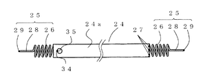
又、実施の形態2の発熱体ユニットにおいて、図12及至図14に示す反射用部材24を構成する反射板24aと弾性部25との取付け構造が異なる例として、図15及び図16に示す引っ掛け保持構造について述べる。図15及び図16において、図12及至図14に示した例と異なる点は、反射板24aの一端部側は図10及至図14に示した例と同様に溶接部27にて溶接を行っているが、反射板24aの他端部側は反射板24aの他端部とコイル部26の一端部を溶接部27にて溶接しない構造となっていることである。すなわち、反射板24aの他端部側において、溶接に代わって、弾性部25の一部であるコイル部26のコイル延端部28が位置する一端部に対向した他端側に、コイル部26を形成するコイル線材の端部を加工してフック部34が形成され、かつ反射板24aの一端部にフック係止用孔35が形成されたものであり、そのフック係止用孔35にフック部34が挿入されて引っ掛けられることによりフック部34がフック係止用孔35に係止されて反射板24aに弾性部25が取り付けられるものである。   Further, in the heating unit of the second embodiment, as an example in which the mounting structure of the reflecting plate 24a and the elastic portion 25 constituting the reflecting member 24 shown in FIGS. 12 to 14 is different, the hook shown in FIGS. The holding structure will be described. 15 and 16, the difference from the example shown in FIG. 12 to FIG. 14 is that the one end side of the reflector 24a is welded at the welded portion 27 in the same manner as the example shown in FIG. 10 to FIG. However, the other end portion side of the reflecting plate 24 a has a structure in which the other end portion of the reflecting plate 24 a and one end portion of the coil portion 26 are not welded by the welding portion 27. That is, on the other end side of the reflecting plate 24a, instead of welding, on the other end side facing the one end where the coil extended end portion 28 of the coil portion 26 that is a part of the elastic portion 25 is positioned, The hook portion 34 is formed by processing the end portion of the coil wire material forming the hook, and the hook locking hole 35 is formed at one end portion of the reflecting plate 24a. When the portion 34 is inserted and hooked, the hook portion 34 is locked in the hook locking hole 35 and the elastic portion 25 is attached to the reflecting plate 24a.

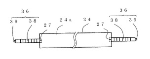
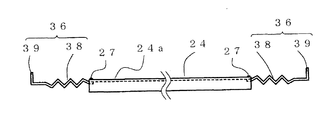
この弾性部25は図10及至図14に示した例と同様に、前記コイル延端部28の先端部はコイル部26の巻き中心軸に対し直交する方向で、かつ前記巻き中心軸より離反する方向に屈曲した屈曲部29が形成されているので、図10及至図14に示した例と同様に、保持部材28のコイル延端係合31にコイル延端部28が係合し、保持部材28の位置規制凹部21に屈曲部29が係合して係止されることになり、同様な効果を有するものである。又、実施の形態2の発熱体ユニットにおいて、図12及至図14に示す反射用部材24の一部を構成する弾性部25が異なる場合の他の例を図17及び図18に示し説明する。図17及び図18において、図12及至図14に示した例と異なる点は、弾性部25に代えて弾性力を有する金属板からなる弾性部36が設けられ点であり、さらに、この弾性部36は、図6及び図7に示す弾性部23と同様な屈曲形状で形成している。   As in the example shown in FIGS. 10 to 14, the elastic portion 25 has a distal end portion of the coil extended end portion 28 in a direction perpendicular to the winding center axis of the coil portion 26 and away from the winding center axis. Since the bent portion 29 that is bent in the direction is formed, the coil extension end portion 28 is engaged with the coil extension end engagement 31 of the holding member 28 in the same manner as in the example shown in FIGS. The bent portion 29 is engaged and locked to the position restricting recess 21 of 28, and has the same effect. Further, in the heating element unit of the second embodiment, another example in which the elastic portion 25 constituting a part of the reflecting member 24 shown in FIGS. 12 to 14 is different will be described with reference to FIGS. 17 and 18, the difference from the example shown in FIGS. 12 to 14 is that an elastic portion 36 made of a metal plate having an elastic force is provided instead of the elastic portion 25, and this elastic portion. 36 is formed in the same bent shape as the elastic part 23 shown in FIG.6 and FIG.7.

図17及至図18に示す反射用部材24の弾性部36は図6乃至図7に示す弾性部23と同様に反射板24aの板幅より小幅に形成された板体として形成され、その板体の一端部は板体の長手方向が第1のガラス管1、第2のガラス管9、あるいは発熱体構成部2の長手方向に沿って配置されるように反射板24aの一端部の溶接部27にて溶接されている。さらに、板体の長手方向の中央側には図6乃至図7に示す弾性部23と同様な波状、鋸歯状あるいは蛇腹状等の屈曲部38が形成されることにより、屈曲部38は反射板24aの伸縮によって発生した張力に応じて伸縮自在な弾性変形を行うこととなる。又、反射板24aに溶接された前記一端部と対向して位置する他端部には、図12乃至図16に示すコイル延端部29あるいは図6乃至図7に示す弾性部23の突起20と同様な役割を果たす突起39が板体の板面に対し垂直方向で、かつ外側方向(スラスト軸方向より離反する方向)に屈曲されて形成され、位置規制凹部21に係止されることとなる。尚、弾性部36あるいは屈曲部38の板幅寸法は適度な伸縮自在性と反射用部材24の一部としての強度とを考慮しながら反射板24aの板幅寸法より小さく、かつ同幅寸法形状で設定しているが、反射板24aの材質、発熱体ユニットの構成等の条件によって任意の寸法・形状にしてもよいことはいうまでもない。   The elastic portion 36 of the reflecting member 24 shown in FIGS. 17 to 18 is formed as a plate formed smaller than the plate width of the reflecting plate 24a in the same manner as the elastic portion 23 shown in FIGS. The welded portion at one end of the reflector 24a is arranged so that the longitudinal direction of the plate is arranged along the longitudinal direction of the first glass tube 1, the second glass tube 9, or the heating element component 2 It is welded at 27. Further, a bent portion 38 having a wave shape, a sawtooth shape, a bellows shape or the like similar to the elastic portion 23 shown in FIGS. 6 to 7 is formed on the center side in the longitudinal direction of the plate body. The elastic deformation is performed according to the tension generated by the expansion / contraction of 24a. Further, at the other end portion facing the one end portion welded to the reflecting plate 24a, the coil extension end portion 29 shown in FIGS. 12 to 16 or the protrusion 20 of the elastic portion 23 shown in FIGS. A projection 39 having the same function as that of the plate is formed by being bent in a direction perpendicular to the plate surface of the plate body and in an outward direction (a direction away from the thrust axis direction) and locked to the position regulating recess 21. Become. The plate width size of the elastic portion 36 or the bent portion 38 is smaller than the plate width size of the reflecting plate 24a in consideration of appropriate stretchability and strength as a part of the reflecting member 24, and has the same width size shape. However, it goes without saying that the size and shape may be arbitrarily determined depending on conditions such as the material of the reflector 24a and the configuration of the heating element unit.

以上説明した弾性部25、弾性部36は、上述した形状、材料、個数及び位置等に拘束されるのではなく、反射板24aの機能を阻害することなく反射板24aの長手方向に弾性機能を得るものであれば、例えば反射板24aの両端にそれぞれ設けず片端のみに設けることでもよいことはいうまでもない。   The elastic part 25 and the elastic part 36 described above are not restricted by the shape, material, number, position, etc. described above, but have an elastic function in the longitudinal direction of the reflecting plate 24a without hindering the function of the reflecting plate 24a. It goes without saying that, for example, it may be provided only at one end without being provided at both ends of the reflecting plate 24a.

又、実施の形態2の発熱体ユニットの輻射強度の状態は、実施の形態1の発熱体ユニットにおいて図8及び図9を用いて説明した内容と同様であることは言うまでもない。   Needless to say, the radiation intensity of the heating element unit according to the second embodiment is the same as that described with reference to FIGS. 8 and 9 in the heating element unit according to the first embodiment.

以上のように、実施の形態1及び実施の形態2の発熱体ユニットにおいて弾性部17,22,23,25,36を説明したが、それらの構成に限定されるのではなく、反射板16a,24a,の熱膨張を吸収することができれば公知の構成を用いてもよい。   As described above, the elastic portions 17, 22, 23, 25, and 36 have been described in the heating element units according to the first and second embodiments. However, the elastic portions 17, 22, 23, 25, and 36 are not limited to those configurations. A known configuration may be used as long as the thermal expansion of 24a can be absorbed.

尚、実施の形態1乃至2の発熱体ユニットにおいては、発熱体2aは平面を有する板状体で説明したが、この板状体は硬質あるいは軟質なものでもよく、前記軟質なものとして、例えば、炭素繊維等を含む繊維状の帯状体や、その帯状体に切れ込みが入っている形状等の場合でも良く、また、平面は凸凹面であっても平均的に略平面を有する発熱体であれば本願発明と同様の効果が得られる。   In the heating element units of the first and second embodiments, the heating element 2a has been described as a flat plate, but this plate may be hard or soft. In addition, it may be a fibrous strip containing carbon fiber or the like, or a shape in which the strip is cut, or a heating element having an average plane even if the plane is uneven. Thus, the same effect as the present invention can be obtained.

また、各実施の形態における発熱体2aとして指向性のある板状体のものを用いて説明したが、発熱体2aとして、前記帯状体を螺旋状に丸巻きされた指向性のない形状、丸棒形状、あるいは略四角の角柱形状のものであっても反射板12aあるいは反射板24aを用いることにより、一方向への指向性を高めることができる。   Further, although the heat generating element 2a in each embodiment has been described using a directional plate-like object, the heat generating element 2a has a non-directional shape, a round shape, which is formed by spirally winding the belt-like element. Directivity in one direction can be enhanced by using the reflecting plate 12a or the reflecting plate 24a even if it has a rod shape or a substantially rectangular prism shape.

本発明にかかる発熱体ユニットは、反射板を有する反射板用部材の少なくとも一部に弾性部を設けることにより、寿命が長く、小型で効率が高く、そして各種用途において容易に適応することができる汎用性の高い熱源としての発熱体ユニットを提供することが可能である。   The heating element unit according to the present invention has a long life, a small size, high efficiency, and can be easily adapted to various applications by providing an elastic portion on at least a part of the reflecting plate member having the reflecting plate. It is possible to provide a heating element unit as a highly versatile heat source.

実施の形態1の発熱体ユニットの構造を示す正面図The front view which shows the structure of the heat generating body unit of Embodiment 1. FIG. 同発熱体ユニットのZ−Z断面における断側面図Sectional side view in the ZZ cross section of the same heating element unit 同発熱体ユニットにおける反射板の端部を示す切欠斜視図Cutaway perspective view showing end of reflector in same heating element unit 同反射板を示す平面図Plan view showing the reflector 同発熱体ユニットにおける反射板の異なる例を示す平面図The top view which shows the example from which the reflecting plate in the same heat generating unit differs 同発熱体ユニットにおける反射板の他の異なる例を示す平面図The top view which shows the other different example of the reflecting plate in the same heating element unit 同反射板の正面図Front view of the reflector 同発熱体ユニットの一実施例における輻射強度曲線図Radiation intensity curve in one embodiment of the heating element unit 同発熱体ユニットの他の実施例における輻射強度曲線図Radiation intensity curve diagram in another embodiment of the same heating element unit 実施の形態2の発熱体ユニットの構造を示す正面図The front view which shows the structure of the heat generating body unit of Embodiment 2. FIG. 同発熱体ユニットのY−Y断面における断側面図Sectional side view in YY section of the heating element unit 同発熱体ユニットにおける反射用部材を示す切欠斜視図Cutaway perspective view showing a reflecting member in the heating element unit 同反射用部材を示す平面図Plan view showing the reflection member 同反射用部材を示す正面図Front view showing the reflection member 同発熱体ユニットにおける反射用部材の異なる例を示す平面図The top view which shows the example from which the member for reflection in the same heat generating unit differs 同反射用部材を示す正面図Front view showing the reflection member 同発熱体ユニットにおける反射用部材の他の異なる例を示す平面図The top view which shows the other different example of the member for reflection in the same heat generating body unit 同反射用部材を示す正面図Front view showing the reflection member

符号の説明Explanation of symbols

1 第1のガラス管
2 発熱体構成部
2a 発熱体
3 保持具
4 内部リード線
5 コイル部
6 スプリング部
7 モリブデン箔
8 外部リード線
9 第2のガラス管
10 保持部材
11 係合孔
12 係止用凹部
13 第1の保持用凹部
14 接着剤
15 第2の保持用凹部
16 反射板用部材
16a 反射板
17 弾性部
18 反射板係合部
19 回動阻止部
20 突起
21 位置規制凹部
22 弾性部
23 弾性部
24 反射板用部材
24a 反射板
25 弾性部
26 コイル部
27 溶接部
28 コイル延端部
29 屈曲部
30 保持部材
31 コイル延端係合部
32 規制係止片
34 フック部
35 フック係止用孔
36 弾性部
38 屈曲部
39 突起
40 輻射強度曲線
41 輻射強度曲線
42 輻射強度曲線
DESCRIPTION OF SYMBOLS 1 1st glass tube 2 Heating body structure part 2a Heating body 3 Holder 4 Internal lead wire 5 Coil part 6 Spring part 7 Molybdenum foil 8 External lead wire 9 2nd glass tube 10 Holding member 11 Engagement hole 12 Locking Concave portion 13 first holding concave portion 14 adhesive 15 second holding concave portion 16 reflecting plate member 16a reflecting plate 17 elastic portion 18 reflecting plate engaging portion 19 rotation preventing portion 20 protrusion 21 position regulating concave portion 22 elastic portion DESCRIPTION OF SYMBOLS 23 Elastic part 24 Reflector member 24a Reflector 25 Elastic part 26 Coil part 27 Welding part 28 Coil extended end part 29 Bending part 30 Holding member 31 Coil extended end engaging part 32 Restriction locking piece 34 Hook part 35 Hook locking Hole 36 Elastic part 38 Bent part 39 Projection 40 Radiation intensity curve 41 Radiation intensity curve 42 Radiation intensity curve

Claims (10)

発熱部を有する発熱体と、その発熱体の長手方向に位置する端部に取付けられた保持具と、前記発熱体に直接あるいは間接に電気的に接続されて前記発熱体に外部からの電力を供給する電力供給部材と、前記発熱体、前記保持具、及び電力供給部材の一部を第1の内部空間に配置した第1の透熱管と、前記第1の透熱管を第2の内部空間に配置した第2の透熱管と、前記第1の透熱管と第2の透熱管とが所定の空隙空間を有して配設されるように設けられた保持部材と、前記第1の透熱管と前記第2の透熱管との隙間に配設された反射板とその反射板に設けられた弾性部とを有する反射用部材と、前記反射板を前記発熱体に対して所定の位置に配置されるように前記保持部材、第1の透熱管、あるいは第2の透熱管の少なくとも何れかに直接あるいは間接的に設けられた位置規制部とによって構成され、通電された発熱体の熱により生じる前記反射板への熱ストレスを前記弾性部によって吸収することを特徴とする発熱体ユニット。   A heating element having a heating part, a holder attached to an end located in the longitudinal direction of the heating element, and an electric power source connected to the heating element directly or indirectly to supply electric power to the heating element from the outside A power supply member to be supplied, a first heat permeable tube in which a part of the heating element, the holder, and the power supply member are arranged in a first internal space, and the first heat permeable tube in a second internal space A second heat-permeable tube disposed on the holding member, a holding member provided so that the first heat-permeable tube and the second heat-permeable tube have a predetermined gap space, and the first heat-permeable tube. A reflecting member having a reflecting plate disposed in a gap between the heat pipe and the second heat-transmitting tube and an elastic portion provided on the reflecting plate, and the reflecting plate at a predetermined position with respect to the heating element It is directly attached to at least one of the holding member, the first heat transfer tube, and the second heat transfer tube so as to be disposed. The heating element unit is constituted by a position restricting portion provided indirectly, and absorbs thermal stress to the reflecting plate caused by heat of the energized heating element by the elastic portion. 前記反射用部材の弾性部は、前記発熱体の長手方向への伸縮を吸収することを特徴とする請求項1に記載の発熱体ユニット。   The heating element unit according to claim 1, wherein the elastic portion of the reflecting member absorbs expansion and contraction in the longitudinal direction of the heating element. 前記反射用部材の弾性部は、前記発熱体の長手方向への伸縮を吸収する弾性を有する弾性部材であり、その弾性部材は反射板に機械的に結合されていることを特徴とする請求項1または2に記載の発熱体ユニット。   The elastic part of the reflection member is an elastic member having elasticity that absorbs expansion and contraction in the longitudinal direction of the heating element, and the elastic member is mechanically coupled to a reflection plate. The heating element unit according to 1 or 2. 前記反射板は金属薄板で形成されることを特徴とする請求項1乃至3のいずれか一項に記載の発熱体ユニット。   The heating element unit according to any one of claims 1 to 3, wherein the reflecting plate is formed of a thin metal plate. 前記反射板はニッケル、ステンレス鋼、又はニクロムの金属薄板で形成されることを特徴とする請求項4に記載の発熱体ユニット。   The heating element unit according to claim 4, wherein the reflection plate is formed of a thin metal plate of nickel, stainless steel, or nichrome. 前記弾性部材は板材を屈曲し形成されることを特徴とする請求項3に記載の発熱体ユニット。   The heating element unit according to claim 3, wherein the elastic member is formed by bending a plate material. 前記弾性部材は線材をコイル状に形成されることを特徴とする請求項3に記載の発熱体ユニット。   The heating element unit according to claim 3, wherein the elastic member is formed of a wire in a coil shape. 前記弾性部材はモリブデンやタングステン、ニッケル、ステンレス鋼、又はニクロムなどの金属で形成されることを特徴とする請求項6乃至請求項7のいずれか一項に記載の発熱体ユニット。   The heating element unit according to any one of claims 6 to 7, wherein the elastic member is formed of a metal such as molybdenum, tungsten, nickel, stainless steel, or nichrome. 前記発熱体は炭素系物質を含み、かつ発熱体の長手方向に沿って形成された側壁の少なくとも一部に平面部を形成するとともに、その平面部に対向し、かつ前記発熱体を介した前記平面部の裏面側方向に前記発熱体側に向けて熱を反射せしめる前記反射用部材の反射面が配置されることを特徴とする請求項1乃至請求項8のいずれか一項に記載の発熱体ユニット。   The heating element includes a carbon-based material, and forms a flat portion on at least a part of a side wall formed along the longitudinal direction of the heating element, faces the flat portion, and passes through the heating element. The heating element according to any one of claims 1 to 8, wherein a reflecting surface of the reflecting member that reflects heat toward the heating element side is arranged in a back surface side direction of the flat portion. unit. 前記発熱体は炭素系物質を含み、かつ発熱体の長手方向に沿って形成された側壁の少なくとも一部に平面部を形成するとともに、その平面部の仮想延長面に交差し、かつ前記平面部の裏面側方向に前記発熱体側に向けて反射される前記反射用部材の反射面が配置されることを特徴とする請求項1乃至請求項8のいずれか一項に記載の発熱体ユニット。   The heating element includes a carbon-based material, and forms a plane portion on at least a part of a side wall formed along the longitudinal direction of the heating element, intersects with a virtual extension surface of the plane portion, and the plane portion The heating element unit according to any one of claims 1 to 8, wherein a reflection surface of the reflecting member that is reflected toward the heating element side is disposed in a rear surface side direction of the heating element unit.
JP2008082809A 2008-03-27 2008-03-27 Heating element unit Pending JP2009238564A (en)

Priority Applications (1)

Application Number Priority Date Filing Date Title
JP2008082809A JP2009238564A (en) 2008-03-27 2008-03-27 Heating element unit

Applications Claiming Priority (1)

Application Number Priority Date Filing Date Title
JP2008082809A JP2009238564A (en) 2008-03-27 2008-03-27 Heating element unit

Publications (1)

Publication Number Publication Date
JP2009238564A true JP2009238564A (en) 2009-10-15

Family

ID=41252260

Family Applications (1)

Application Number Title Priority Date Filing Date
JP2008082809A Pending JP2009238564A (en) 2008-03-27 2008-03-27 Heating element unit

Country Status (1)

Country Link
JP (1) JP2009238564A (en)

Cited By (1)

* Cited by examiner, † Cited by third party
Publication number Priority date Publication date Assignee Title
CN114270480A (en) * 2019-08-21 2022-04-01 琳科技股份有限公司 Gasifier

Cited By (2)

* Cited by examiner, † Cited by third party
Publication number Priority date Publication date Assignee Title
CN114270480A (en) * 2019-08-21 2022-04-01 琳科技股份有限公司 Gasifier
CN114270480B (en) * 2019-08-21 2025-02-11 琳科技股份有限公司 Gasifier

Similar Documents

Publication Publication Date Title
KR100914814B1 (en) Heating unit and heating apparatus
TWI723949B (en) Heat dissipation device having irregular shape
JP2005085682A (en) Infrared light bulb, heating device and electronic device
KR100382658B1 (en) Fusing roller apparatus of electrophotographic image forming apparatus
JP2009238564A (en) Heating element unit
JP5383741B2 (en) Heating element unit
JP2008218267A (en) Heating unit and heating device
JP2006286372A (en) Infrared ray carbon heater
JP4340677B2 (en) Heat generating unit and heating device
JP4733099B2 (en) Heating unit and heating device
JP4741924B2 (en) Infrared bulb and heating device
JP2007122893A (en) Infrared bulb and heating device
JP2005085698A (en) Electric heater
JP2001249332A (en) Liquid crystal display
JP3834320B2 (en) Heating equipment, drying equipment, cooking equipment, copiers, printing machines, and industrial paint dryers with infrared bulbs
JP3334711B1 (en) Electric stove
JP2007200798A (en) Heat generating structure, heat generating unit, and heating device
JP2007200640A (en) Heat generating unit and heating device
JP2007103292A (en) Infrared bulb and heating device
JP4741929B2 (en) Infrared bulb and heating device
JP3555586B2 (en) Lamp device
JP4107205B2 (en) Electric heater
JP7485581B2 (en) Infrared sensor element and infrared sensor
JP2003035422A (en) Electric stove
JP3834319B2 (en) Infrared bulb, heating / heating device, and method of manufacturing infrared bulb