JP2007200640A - Heat generation unit and heating device - Google Patents
Heat generation unit and heating device Download PDFInfo
- Publication number
- JP2007200640A JP2007200640A JP2006016033A JP2006016033A JP2007200640A JP 2007200640 A JP2007200640 A JP 2007200640A JP 2006016033 A JP2006016033 A JP 2006016033A JP 2006016033 A JP2006016033 A JP 2006016033A JP 2007200640 A JP2007200640 A JP 2007200640A
- Authority
- JP
- Japan
- Prior art keywords
- heat generating
- heating element
- generating unit
- lead wire
- heating
- Prior art date
- Legal status (The legal status is an assumption and is not a legal conclusion. Google has not performed a legal analysis and makes no representation as to the accuracy of the status listed.)
- Pending
Links
Images


Landscapes
- Resistance Heating (AREA)
- Electric Stoves And Ranges (AREA)
Abstract
Description
本発明は、ガラス管に収納した発熱体を有する発熱ユニット及びその発熱ユニットを用いた加熱装置に関し、特に発熱体に対して電力供給を行うリード線の改良に関するものである。 The present invention relates to a heating unit having a heating element housed in a glass tube and a heating device using the heating unit, and more particularly to an improvement in a lead wire that supplies power to the heating element.
従来の発熱ユニットにおいては、長尺の発熱体の端部にリード線を電気的に接続するための巻付け部と、この巻付け部に電力供給を行うとともに、発熱体の伸縮動作を吸収するコイル状部とを有して構成されている(例えば、特許文献1参照。)。 In a conventional heating unit, a winding part for electrically connecting a lead wire to the end of a long heating element, power is supplied to the winding part, and the expansion and contraction operation of the heating element is absorbed. A coil-shaped part is included (see, for example, Patent Document 1).
図8は、従来の発熱ユニットの一般的な構成を示す正面図である。図8に示した従来の発熱ユニットおいては、丸棒状に形成された長尺の発熱体101と、発熱体101が封入された円管状のガラス管102と、発熱体101の両端部に固着され、外部導入線107にモリブデン箔106を介して電気的に接続されたリード線103とを有して構成されている。リード線103には、発熱体101の端部に固着するための巻付け部104と、発熱体101の伸縮動作を吸収するコイル状部105が形成されている。
図8に示すように、従来の発熱ユニットの構成では、発熱体101の両端部に固着された巻付け部104から外側(発熱ユニットの長手方向の両端部側)に導出するようコイル状部105が形成されている。従来の発熱ユニットにおいては、発熱体101の配設位置が発熱領域aであり、巻付け部104から外側(長手方向における外側)の部分が非発熱領域bである。すなわち、非発熱領域bにはリード線103のコイル状部105及びモリブデン箔106を有する封止部分が配設されている。
As shown in FIG. 8, in the configuration of the conventional heat generating unit, the coil-
上記のように構成された従来の発熱ユニットにおいて、非発熱領域bの長さを短くし、発熱ユニット全体の長さに対する発熱領域aの配設比率を高くすることが要望されており、このように非発熱領域bの長さを短くすることにより、結果的にはこの発熱ユニットを組み込んだ加熱装置の小型化を達成することが可能となる。したがって、発熱ユニットにおける非発熱領域bの長さを短くすることが、この分野において解決すべき課題であった。 In the conventional heat generating unit configured as described above, it is desired to shorten the length of the non-heat generating region b and increase the arrangement ratio of the heat generating region a with respect to the entire length of the heat generating unit. In addition, by reducing the length of the non-heat generating region b, it is possible to achieve a reduction in the size of the heating device incorporating this heat generating unit. Therefore, shortening the length of the non-heat generating region b in the heat generating unit has been a problem to be solved in this field.
また、発熱ユニットが組み込まれた加熱装置においては、転倒などによる衝撃が発熱ユニットに加えられた場合、発熱ユニットの全長が長いほど、衝撃力が大きく伝播し、結果としてガラス管の破損や発熱体の断線につながるという問題を有していた。このような問題を解決して安全性及び信頼性の高い発熱ユニット及び加熱装置を提供することがこの分野における解決すべき課題であった。 In addition, in a heating device with a built-in heat generating unit, when an impact due to a fall or the like is applied to the heat generating unit, the longer the total length of the heat generating unit, the larger the impact force propagates, resulting in glass tube breakage or heat Had the problem of leading to disconnection. It was a problem to be solved in this field to solve such problems and to provide a heat generating unit and a heating device with high safety and reliability.
本発明は、従来の発熱ユニット及び加熱装置における課題を解決するものであり、非発熱領域bの長さを短くすることにより、発熱ユニットが組み込まれる加熱装置の小型化を図ると共に、ガラス管の破損や発熱体の断線が生じにくい構成の発熱ユニット及び加熱装置を提供することを目的とする。 The present invention solves the problems in the conventional heat generating unit and heating device, and by reducing the length of the non-heat generating region b, the heating device in which the heat generating unit is incorporated is miniaturized, and the glass tube It is an object of the present invention to provide a heat generating unit and a heating device having a configuration in which breakage and disconnection of the heat generating body are unlikely to occur.
本発明に係る第1の観点の発熱ユニットは、前記目的を達成するために、
長手方向に延設された発熱体と、
前記発熱体を収納するガラス管と、
前記発熱体に電気的に接続され、当該発熱体に電力供給を行うリード線構成部と、を有して構成され、
前記リード線構成部は、前記発熱体の端部に電気的に接続された固定部と、
前記発熱体の伸縮動作を吸収する弾性部と、を有して構成され、
前記発熱体の長手方向の位置において、前記固定部と前記弾性部の少なくとも一部が重なるよう構成されている。
このように構成された、発熱ユニットは非発熱領域が大幅に縮小され、小型化を達成することができる。
In order to achieve the above object, the heat generating unit according to the first aspect of the present invention provides:
A heating element extending in the longitudinal direction;
A glass tube that houses the heating element;
A lead wire component electrically connected to the heating element and supplying power to the heating element,
The lead wire constituting portion includes a fixing portion electrically connected to an end portion of the heating element,
An elastic part that absorbs the expansion and contraction operation of the heating element,
At a position in the longitudinal direction of the heating element, at least a part of the fixed portion and the elastic portion are configured to overlap each other.
In the heat generating unit configured as described above, the non-heat generating region is greatly reduced, and the size reduction can be achieved.
本発明に係る第2の観点の発熱ユニットは、第1の観点の構成における前記リード線構成部の弾性部がコイル状に形成されており、前記弾性部における実質的中心部分に固定部の少なくとも一部が配設されている。このように構成された発熱ユニットは、弾性部において外部からの振動が緩和され、固定部への振動伝搬が大幅に抑制される。 In the heat generating unit according to the second aspect of the present invention, the elastic part of the lead wire constituting part in the structure of the first aspect is formed in a coil shape, and at least a fixed part is provided at a substantially central part of the elastic part. A part is arranged. In the heat generating unit configured as described above, vibration from the outside is reduced in the elastic portion, and vibration propagation to the fixed portion is greatly suppressed.
本発明に係る第3の観点の発熱ユニットは、第1の観点の構成における前記リード線構成部の固定部と弾性部が、1本の金属線により連続して形成されている。このように構成された発熱体ユニットは、部品点数が少なく、製造時において優れた作業性を有する。 In the heat generating unit according to the third aspect of the present invention, the fixed part and the elastic part of the lead wire constituting part in the structure of the first aspect are continuously formed by one metal wire. The heating element unit configured as described above has a small number of parts and has excellent workability during manufacturing.
本発明に係る第4の観点の発熱ユニットは、第1の観点の構成における前記リード線構成部が、発熱体の端部に固着された板状の固定部と、前記固定部の少なくとも一部を内包するコイル状の弾性部で構成されている。このように構成された発熱体ユニットは、発熱体に対する固定部の取付けが容易となり、製造時において優れた作業性を有する。 A heat generating unit according to a fourth aspect of the present invention includes a plate-shaped fixing portion in which the lead wire constituting portion in the configuration according to the first aspect is fixed to an end portion of the heating element, and at least a part of the fixing portion. It is comprised by the coil-shaped elastic part which encloses. The heating element unit configured as described above makes it easy to attach the fixing portion to the heating element, and has excellent workability during manufacturing.
本発明に係る第5の観点の発熱ユニットは、第1の観点から第4の観点の構成における前記リード線構成部の弾性部が、モリブデン線又はタングステン線で形成されている。このように構成された発熱体ユニットは、高温時の電力供給を確実に行えると共に、発熱体の伸縮を確実に吸収できる構成となる。 In the heat generating unit according to the fifth aspect of the present invention, the elastic part of the lead wire constituting part in the constitutions of the first to fourth aspects is formed of a molybdenum wire or a tungsten wire. The heating element unit configured as described above can reliably supply power at a high temperature and can reliably absorb expansion and contraction of the heating element.
本発明に係る第6の観点の発熱ユニットは、第1の観点から第5の観点の構成における前記リード線構成部の弾性部が、前記ガラス管の内壁に近接して配置されている。このように構成された発熱ユニットは、ガラス管からの振動が弾性部において吸収され固定部の振動が大幅に抑制される。 In the heat generating unit according to the sixth aspect of the present invention, the elastic part of the lead wire constituting part in the constitution of the first aspect to the fifth aspect is arranged close to the inner wall of the glass tube. In the heat generating unit configured as described above, the vibration from the glass tube is absorbed by the elastic portion, and the vibration of the fixed portion is greatly suppressed.
本発明に係る第7の観点の発熱ユニットは、第1の観点から第6の観点の構成における前記発熱体と前記リード線構成部との間に電気伝導性及び放熱性を有する保持部材を設けている。このように構成された発熱ユニットは、発熱体に対して効率高く給電できると共に、発熱体から伝導する熱が保持部材で放散され、リード線構成部への伝熱が抑制される。 A heat generating unit according to a seventh aspect of the present invention is provided with a holding member having electrical conductivity and heat dissipation between the heat generating element and the lead wire component in the structure according to the first to sixth aspects. ing. The heat generating unit configured as described above can efficiently supply power to the heat generating element, and heat conducted from the heat generating element is dissipated by the holding member, so that heat transfer to the lead wire constituting part is suppressed.
本発明に係る第8の観点の発熱ユニットは、第1の観点から第7の観点の構成における前記発熱体が炭素系物質を含む材料で形成されている。このように構成された発熱ユニットは、効率の高い発熱手段となる。 In the heat generating unit according to the eighth aspect of the present invention, the heat generating element in the configuration according to the first aspect to the seventh aspect is formed of a material containing a carbon-based substance. The heat generating unit configured in this way becomes a highly efficient heat generating means.
本発明に係る第9の観点の発熱ユニットは、第1の観点から第8の観点の構成における前記発熱体が、モリブデン又はタングステンの棒状形成品である。このように構成された発熱ユニットは、製造時の取扱いが容易で、製造が容易となる。 In the heat generating unit according to the ninth aspect of the present invention, the heat generating element in the configuration according to the first aspect to the eighth aspect is a rod-shaped product of molybdenum or tungsten. The heat generating unit configured in this way is easy to handle during manufacture and easy to manufacture.
本発明に係る第10の観点の発熱ユニットは、第8の観点から第9の観点の構成における前記ガラス管の両端を封着し、前記ガラス管内に不活性ガスが封入されて構成されている。このように構成された発熱ユニットは、効率の高い発熱手段となる。 A heat generating unit according to a tenth aspect of the present invention is configured by sealing both ends of the glass tube in the configuration of the eighth aspect to the ninth aspect and enclosing an inert gas in the glass tube. . The heat generating unit configured in this way becomes a highly efficient heat generating means.
本発明に係る第11の観点の発熱ユニットは、第1の観点から第7の観点の構成における前記発熱体が、珪化モリブデン、炭化珪素、ランタンクロマイト、鉄・クロム・アルミ系合金又はニッケル・クロム系合金から選ばれた少なくとも1つの材料による形成品である。このように構成された発熱ユニットは、製造時の取扱いが容易で、製造が容易となる。 According to an eleventh aspect of the present invention, in the heat generating unit according to the first to seventh aspects, the heating element according to the constitution of the seventh aspect is molybdenum silicide, silicon carbide, lanthanum chromite, iron / chromium / aluminum alloy or nickel / chromium. It is a formed article made of at least one material selected from a series alloy. The heat generating unit configured in this way is easy to handle during manufacture and easy to manufacture.
本発明に係る第12の観点の加熱装置においては、第1の観点から第11の観点の構成を有する発熱ユニットと、前記発熱ユニットの背面に配設された反射板と、前記発熱ユニットと前記反射板とを取付ける筐体と、を具備している。このように構成された加熱装置は、小型化が図られ信頼性の高い発熱ユニットを用いているため、小型化と信頼性を有する加熱手段となる。 In a heating apparatus according to a twelfth aspect of the present invention, a heat generating unit having the structure of the first aspect to the eleventh aspect, a reflector disposed on the back surface of the heat generating unit, the heat generating unit, A housing for mounting the reflector. Since the heating device configured in this way is downsized and uses a highly reliable heat generating unit, it becomes a heating means having downsizing and reliability.
本発明によれば、発熱ユニットにおける非発熱領域を小さく構成することが可能となり、当該発熱ユニットが組み込まれた加熱装置の小型化を達成することができると共に、信頼性及び安全性の高い発熱ユニット及び加熱装置を提供することが可能となる。 According to the present invention, it is possible to configure a non-heat generating region in the heat generating unit to be small, and it is possible to achieve downsizing of a heating device in which the heat generating unit is incorporated, and also a highly reliable and safe heat generating unit. And a heating device can be provided.
以下、本発明に係る発熱ユニット及び加熱装置の好適な実施例を添付の図面を参照しつつ説明する。 Hereinafter, preferred embodiments of a heat generating unit and a heating device according to the present invention will be described with reference to the accompanying drawings.
《実施例1》
図1及び図2を用いて、本発明に係る実施例1の発熱ユニットについて説明する。図1は本発明に係る実施例1の発熱ユニットの構成を示す正面図である。図2は本発明に係る実施例1の発熱ユニットのリード線構成部を拡大して示す図である。
Example 1
The heat generating unit according to the first embodiment of the present invention will be described with reference to FIGS. 1 and 2. FIG. 1 is a front view showing the configuration of the heat generating unit according to the first embodiment of the present invention. FIG. 2 is an enlarged view showing a lead wire constituent part of the heat generating unit according to the first embodiment of the present invention.
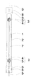
実施例1の発熱ユニットは、炭素系物質を含む材料により長手方向に延びる丸棒状に形成された発熱体1と、この発熱体1を収納するガラス管2と、発熱体1に電気的に接続され、発熱ユニットの外部に設けられた電源(図示省略)から発熱体1に電力供給を行うリード線構成部3で構成されている。実施例1における発熱体1は、炭素系物質を含む材料により形成されているが、例えば黒鉛などの結晶化炭素、抵抗値調整物質、及びアモルファス炭素の混合物からなる炭素系物質の材料により形成されており、直径2mm、長さ300mmの丸棒状に形成されている。リード線構成部3は、発熱体1に電気的に接続し固着するための固定部4と、発熱体1の伸縮を吸収するための弾性部5とを有している。弾性部5は固定部4を内包し、固定部4と弾性部5が発熱体1の長手方向の位置において重なるよう構成されている。
The heat generating unit of Example 1 is electrically connected to the heat generating
図1に示すように、実施例1の発熱ユニットにおいて、ガラス管2の両端は封止するよう溶着されており、リード線構成部3に接続されたモリブデン箔8を埋設した封止部6が形成されている。ガラス管2の内部には、発熱体1及びリード線構成部3とともにアルゴン、窒素などの不活性ガス7が封入されている。リード線構成部3の固定部4は発熱体1の端部に直接的に接合されており、リード線構成部3の弾性部5はモリブデン箔8を介して外部導入線9に接続されている。
As shown in FIG. 1, in the heat generation unit of Example 1, both ends of the
図2は実施例1の発熱ユニットにおけるリード線構成部3の拡大図である。リード線構成部3は一本のモリブデン線で形成されており、固定部4と弾性部5が連続して形成されている。固定部4は、弾性部5の内周側に配置されており、発熱体1の両端部に巻回部分が装着されて固定されている。固定部4の巻回部分は、発熱体1の直径より多少細く形成されたコイル状であり、この巻回部分に発熱体1の端部をねじ込み挿入することにより互いに固着するよう構成されている。弾性部5は加熱時に生じる発熱体1の伸張と、電源遮断時に生じる発熱体1の収縮の各動作を吸収する。実施例1の発熱ユニットにおいては、巻回部分である固定部4を構成したモリブデン線が、そのまま弾性部5を形成している。固定部4の巻回部分の外周部分から所定距離を有した外側の位置にコイル状の弾性部5が形成されている。すなわち、弾性部5のコイル状と実質的に同軸上に固定部4の巻回部分が所定距離を有して形成されており、固定部4と弾性部5の位置は発熱体1の長手方向においてほとんど重なった位置となっている。
この結果、実施例1の発熱ユニットにおいては、従来の発熱ユニットに比して非発熱領域を小さく形成することが可能となる。
FIG. 2 is an enlarged view of the lead
As a result, in the heat generating unit of the first embodiment, it is possible to form a non-heat generating region smaller than the conventional heat generating unit.
以上のように、本発明に係る実施例1の発熱ユニットにおいて、リード線構成部3の固定部4と弾性部5が発熱体1の長手方向における位置において重なるよう構成することにより、従来の発熱ユニットと同じ発熱体1を用いても発熱ユニットの長手方向の全長を短くすることが可能となる。したがって、当該発熱ユニットが組み込まれた加熱装置は小型化を達成することができる。
また、実施例1の発熱ユニットを組み込んだ加熱装置が転倒などにより当該発熱ユニットに対して衝撃が加えられた場合でも、当該発熱ユニットの長手方向の全長が短く形成されているため、発熱ユニットに加わる衝撃力は小さくなり、結果としてガラス管2などの破損が起こりにくい構成の発熱ユニットの実現が可能となる。
As described above, in the heat generating unit according to the first embodiment of the present invention, the fixing
Even when the heating device incorporating the heat generating unit of Example 1 is subjected to an impact on the heat generating unit due to a fall or the like, the heat generating unit has a short overall length in the longitudinal direction. The applied impact force is reduced, and as a result, it is possible to realize a heat generating unit having a configuration in which the
さらに、加熱装置が転倒などにより衝撃を受けた発熱ユニットの内部の発熱体1においては、発熱体1の両端部の外周側に直径の大きなコイル状の弾性部5が形成されているため、ガラス管2からの衝撃は弾性部5によりある程度吸収されると共に、発熱体1自体の振幅はガラス管2の内壁と弾性部5の外周により規制されて小さく抑制される。なお、発熱体1の両端部に配置される弾性部5の間の距離を可能な限り短くすると共に、弾性部5の外周をガラス管2の内壁に近接、若しくは接触させることにより、上記のような衝撃による発熱体1の振幅はさらに小さくなり、発熱体1がガラス管2の内壁に衝突することによる断線をさらに軽減することが可能となる。
Further, in the
なお、実施例1の発熱体1は炭素系物質を含む材料で形成された丸棒状の形成品で説明したが、材料として炭素系物質を含む織物や不織布、又はモリブデンやタングステンなどの各種発熱材料を用いることが可能であり、これらの材料により形成された発熱体であっても本発明の効果に影響するものではない。特に、織物や不織布で発熱体を形成した場合には、発熱体の端部に固定部となる金属線を巻き付けることにより容易に固着することが可能となる。
In addition, although the
また、実施例1のリード線構成部3は1本のモリブデン線により形成した例で説明したが、タングステン線又はニッケル線などの1本の金属線を用いて固定部4と弾性部5とを形成してもよい。
また、発熱体1の形状についても丸棒状に限定されるものではなく、板状や、断面が多角形状であってもよい。ただし、板状の発熱体を用いた場合には、リード線構成部の固定部は発熱体の端部に直接巻付ける巻回部分を用いる必要はない、この場合には、例えば発熱体の端部を挟み付ける固定部材を取り付け、その固定部材の外側に弾性部5を設ける構成でも良い。このように、板状の発熱体を用いることにより、指向性を有する加熱手段となり、被加熱物に対する加熱効率が高くなるという効果を有する。
In addition, although the lead
Further, the shape of the
さらに、実施例1ではガラス管2の両端に封止部6を形成し、ガラス管2の内部に不活性ガス7を封入した例で説明したが、ガラス管の両端を開口して、ガラス管の内部に空気が流通する構成とすると共に、発熱体1を珪化モリブデン、炭化珪素、ランタンクロマイト、鉄・クロム・アルミ系合金又はニッケル・クロム系合金などの材料により形成してもよい。
Furthermore, in Example 1, although the sealing
なお、実施例1の発熱ユニットにおいて、リード線構成部3を発熱体1の両端に設けた例で説明したが、リード線構成部3を発熱体1の一方に設け、他方にはリード線構成部3の固定部4だけで弾性部5を設けない構成でも同様の効果を奏する。
また、実施例1の発熱ユニットにおいては、弾性部5の内部に固定部4を配設した例で説明したが、固定部と弾性部が並行に設けられた構成でも、同様の効果を奏する。
In the heat generating unit according to the first embodiment, the lead
In the heat generating unit of the first embodiment, the example in which the fixing
《実施例2》
以下、本発明に係る実施例2の発熱ユニットについて図3及び図4を用いて説明する。図3は本発明に係る実施例2の発熱ユニットの構成を示す正面図である。図4は本発明に係る実施例2の発熱ユニットのリード線構成部を拡大して示した図である。
Example 2
Hereinafter, the heat generating unit according to the second embodiment of the present invention will be described with reference to FIGS. 3 and 4. FIG. 3 is a front view showing the configuration of the heat generating unit according to the second embodiment of the present invention. FIG. 4 is an enlarged view of the lead wire constituting portion of the heat generating unit according to the second embodiment of the present invention.
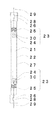
実施例2の発熱ユニットは、炭素系物質を含む材料により長手方向に延びる板状に形成された発熱体21と、この発熱体21を収納するガラス管22と、発熱体21に電気的に接続され、発熱ユニットの外部に設けられた電源(図示省略)から発熱体21に電力供給を行うリード線構成部23で構成されている。実施例2における発熱体21は、炭素系物質を含む材料により形成されているが、例えば黒鉛などの結晶化炭素、抵抗値調整物質、及びアモルファス炭素の混合物からなる炭素系物質の材料により形成されている。リード線構成部23は発熱体21に電気的に接続し固着するためのニッケル板で形成された固定部24と、発熱体21の伸縮を吸収するための弾性部25を有している。弾性部25は固定部24の一部を内包し、固定部24と弾性部25が発熱体21の長手方向の位置において重なるよう構成されている。
The heat generating unit of Example 2 is electrically connected to the
図3に示すように、実施例2の発熱ユニットにおいて、ガラス管22の両端は封止するよう溶着されており、リード線構成部23に接続されたモリブデン箔28を埋設した封止部26が形成されている。ガラス管22の内部には、発熱体21及びリード線構成部23とともに不活性ガス27が封入されている。リード線構成部23の固定部24は発熱体21の端部を挟み込み接合されており、リード線構成部23の弾性部25はモリブデン箔28を介して外部導入線29に接続されている。
As shown in FIG. 3, in the heat generation unit of Example 2, both ends of the
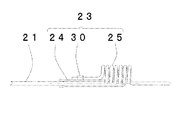
図4は実施例2の発熱ユニットにおけるリード線構成部23の拡大図である。リード線構成部23は、発熱体21の端部に固着された固定部24と、コイル状の弾性部25が接続されて構成されている。弾性部25は、モリブデン線で形成され、加熱時に生じる発熱体1の伸張と、電源遮断時に生じる発熱体1の収縮の各動作を吸収する。固定部24は発熱体21の端部を挟み込んで接合するよう構成されたニッケル板で形成されている。弾性部25は固定部24の一部を内包している。
FIG. 4 is an enlarged view of the lead
実施例2においては、弾性部25の端部を固定部24の一部に形成された突出片30に挟んでかしめることにより、固定部24と弾性部25とを固着し電気的に接続している。なお、固定部24と弾性部25との接合方法としては、かしめ接合に限るものではなく、各種接合方法が適用可能である。
In the second embodiment, the fixing
以上のように、本発明に係る実施例2の発熱ユニットにおいて、リード線構成部23の固定部24と弾性部25が発熱体21の長手方向における位置において重なるよう構成することにより、従来の発熱ユニットと同じ発熱体1を用いても実施例2の発熱ユニットの長手方向の全長を短くすることができる。したがって、当該発熱ユニットが組み込まれた加熱装置は小型化を達成することができる。
また、実施例2の発熱ユニットを組み込んだ加熱装置が転倒などにより当該発熱ユニットに対して衝撃が加えられた場合でも、当該発熱ユニットの長手方向の全長が短かく構成されているため、発熱ユニットに加わる衝撃力は大幅に小さくなり、結果としてガラス管22などの破損が起こりにくい構成の発熱ユニットの実現が可能となる。
As described above, in the heat generating unit according to the second embodiment of the present invention, the
Even when the heating device incorporating the heat generating unit of Example 2 is subjected to an impact on the heat generating unit due to overturning or the like, the heat generating unit is configured to have a short overall length in the longitudinal direction. As a result, it is possible to realize a heat generating unit having a configuration in which the
さらに、加熱装置の転倒などにより衝撃を受けた発熱ユニットの内部の発熱体21においては、発熱体21の両端部の外周側に直径の大きなコイル状の弾性部25が形成されているため、ガラス管22からの衝撃は弾性部25によりある程度吸収されると共に、発熱体21自体の振幅はガラス管22の内壁と弾性部25の外周により規制されて小さく抑制される。なお、発熱体21の両端部に配置される弾性部25の間の距離を可能な限り短くすると共に、弾性部25の外周をガラス管22の内壁に近接、若しくは接触させることにより、上記のような衝撃による発熱体21の振幅はさらに小さくなり、発熱体21がガラス管22の内壁に衝突することによる断線をさらに軽減することが可能となる。
Furthermore, in the
なお、本実施例2の発熱体21は炭素系物質を含む板状の形成品で説明したが、材料として炭素系物質を含む織物や不織布、又はモリブデンやタングステンなどの各種発熱材料を用いることが可能であり、これらの材料により形成された発熱体であっても本発明の効果に影響するものではない。特に、織物や不織布で発熱体を形成した場合には、発熱体の端部と固定部との接合をかしめ接合により容易に行うことが可能となり、作業性のさらなる改善が図られる。
また、発熱体21の形状についても板状に限定されるものではなく、丸棒状や、断面が多角形状であってもよい。
In addition, although the
Further, the shape of the
また、実施例2の弾性部25はモリブデン線により形成した例で説明したが、タングステン線又はニッケル線などの金属線を用いて形成してもよい。
また、実施例2の固定部24は板状のニッケル板を用いて説明したが、モリブデン板又はニッケル・クロム系板などの金属板を用いて形成してもよい。
Moreover, although the
Moreover, although the fixing
さらに、実施例2ではガラス管22の両端に封止部26を形成し、ガラス管22の内部に不活性ガス27を封入した例で説明したが、ガラス管22の両端を開口して、ガラス管の内部に空気が流通する構成とすると共に、発熱体21を珪化モリブデン、炭化珪素、ランタンクロマイト、鉄・クロム・アルミ系合金又はニッケル・クロム系合金などの材料により形成してもよい。
なお、実施例2の発熱ユニットにおいて、リード線構成部23を発熱体21の両端に設けた例で説明したが、リード線構成部23を発熱体21の一方に設け、他方にはリード線構成部23の固定部24だけで弾性部25を設けない構成でも同様の効果を奏する。
Further, in the second embodiment, the sealing
In the heat generation unit according to the second embodiment, the lead
《実施例3》
以下、本発明に係る実施例3の発熱ユニットについて図5及び図6を用いて説明する。図5は本発明に係る実施例3の発熱ユニットの構成を示す正面図である。図6は本発明に係る実施例3の発熱ユニットのリード線構成部を拡大して示した図である。
Example 3
Hereinafter, the heat generating unit according to the third embodiment of the present invention will be described with reference to FIGS. 5 and 6. FIG. 5 is a front view showing the configuration of the heat generating unit according to the third embodiment of the present invention. FIG. 6 is an enlarged view of the lead wire constituting portion of the heat generating unit according to the third embodiment of the present invention.
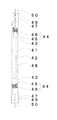
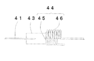
実施例3の発熱ユニットは、炭素系物質を含む材料により長手方向に延びる板状に形成された発熱体41と、この発熱体41を収納するガラス管42と、発熱体41の端部を保持すると共に電気接合された保持部材43と、保持部材43に電気的に接続され、発熱ユニットの外部に設けられた電源(図示省略)から発熱体41に電力供給を行うリード線構成部44で構成されている。実施例3における発熱体41は、炭素系物質を含む材料により形成されているが、例えば黒鉛などの結晶化炭素、抵抗値調整物質、及びアモルファス炭素の混合物からなる炭素系物質の材料で形成されている。リード線構成部44は、保持部材43に電気的に接続し固着するための固定部45と、発熱体41の伸縮を吸収するための弾性部46とを有している。弾性部46が固定部45を内包し、固定部45と弾性部46が発熱体41の長手方向における位置において重なり合うよう構成されている。発熱体41の両端に設けられた保持部材43は、熱伝導性に優れた炭素棒で形成されており、発熱体41から伝導した熱を放熱し、リード線構成部44への熱伝搬を抑制している。
The heat generating unit of Example 3 holds a heating element 41 formed in a plate shape extending in the longitudinal direction with a material containing a carbon-based material, a glass tube 42 that houses the heating element 41, and an end of the heating element 41. And a holding
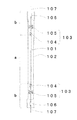
図5に示すように、実施例3の発熱ユニットにおいて、ガラス管42の両端は溶着されており、リード線構成部44に接続されたモリブデン箔49を埋設した封止部47が形成されている。ガラス管42の内部には、発熱体41、保持部材43及びリード線構成部44とともに不活性ガス48が封入されている。リード線構成部44の固定部45は保持部材43を介して発熱体41と電気接合され、リード線構成部44の弾性部46はモリブデン箔49を介して外部導入線50に接続されている。
As shown in FIG. 5, in the heat generating unit of the third embodiment, both ends of the glass tube 42 are welded, and a sealing portion 47 in which
なお、発熱体41と保持部材43の接合方法は、円筒状の保持部材43のスリットに発熱体41の端部を挿入することにより接合されている。この接合において、耐熱性を有する炭素系接着剤を用いてもよい。炭素系接着剤としては、カーボンブラックを熱硬化性樹脂(ポリエステル樹脂やポリイミド樹脂が望ましい)にブレンドし、ペースト状にしたものが好ましい。
The heating element 41 and the holding
図6は実施例3の発熱ユニットにおけるリード線構成部44の拡大図である。リード線構成部44は一本のモリブデン線で形成されており、固定部45と弾性部46が連続して形成されている。固定部45は、弾性部46の内周側に配置されており、発熱体41の両端部に巻回部分が装着されて固定されている。固定部45の巻回部分は、保持部材43の直径より多少細く形成されたコイル状であり、この巻回部分に保持部材43の端部をねじ込み挿入することにより互いに固着するよう構成されている。弾性部46は加熱時に生じる発熱体41の伸張と、電源遮断時に生じる発熱体41の収縮の各動作を吸収する。実施例3の発熱ユニットにおいては、巻回部分である固定部45を構成したモリブデン線が、そのまま弾性部46を形成している。固定部45の巻回部分の外周部分から所定距離を有した外側の位置にコイル状の弾性部46が形成されている。すなわち、弾性部46のコイル状と実質的に同軸上に固定部45の巻回部分が所定距離を有して形成されており、固定部45と弾性部46の位置は発熱体41の長手方向においてほとんど重なった位置となっている。
FIG. 6 is an enlarged view of the lead wire constituting portion 44 in the heat generating unit of the third embodiment. The lead wire constituting portion 44 is formed of a single molybdenum wire, and a fixed
以上のように、本発明に係る実施例3の発熱ユニットにおいて、リード線構成部44の固定部45と弾性部46が発熱体41の長手方向における位置において重なり合うよう構成することにより、従来の発熱ユニットと同じ発熱体41を用いても発熱ユニットの長手方向の全長を短くすることが可能となる。したがって、当該発熱ユニットが組み込まれた加熱装置は小型化を達成することができる。
また、発熱体41とリード線構成部44の間に電気伝導性の良い炭素棒で形成された保持部材43を設けることにより、発熱体41の熱が弾性部46に伝導することを大幅に低減でき、弾性部46のバネ性が保持される。
As described above, in the heat generating unit according to the third embodiment of the present invention, the fixing
Further, by providing a holding
さらに、発熱ユニットを有する加熱装置が転倒などにより衝撃を受けた発熱ユニットの内部の発熱体41においては、発熱体41の両端部の外周側に直径の大きなコイル状の弾性部46が形成されているため、ガラス管42からの衝撃は弾性部46によりある程度吸収されると共に、発熱体41自体の振幅はガラス管42の内壁と弾性部46の外周により規制されて小さく抑制される。なお、発熱体41の両端部に配置される弾性部46の間の距離を可能な限り短くすると共に、弾性部46の外周をガラス管42の内壁に近接、若しくは接触させることにより、上記のような衝撃による発熱体41の振幅はさらに小さくなり、発熱体41がガラス管42の内壁に衝突することによる断線を軽減することが可能となる。 Furthermore, in the heating element 41 inside the heating unit that has been shocked by the heating device having the heating unit falling or the like, coil-shaped elastic portions 46 having large diameters are formed on the outer peripheral sides of both ends of the heating element 41. Therefore, the impact from the glass tube 42 is absorbed to some extent by the elastic portion 46, and the amplitude of the heating element 41 itself is restricted by the inner wall of the glass tube 42 and the outer periphery of the elastic portion 46, and is suppressed to a small extent. In addition, while shortening the distance between the elastic parts 46 arrange | positioned at the both ends of the heat generating body 41 as much as possible, and making the outer periphery of the elastic part 46 adjoin or contact the inner wall of the glass tube 42 as mentioned above. The amplitude of the heat generating element 41 due to an impact is further reduced, and it is possible to reduce the disconnection due to the heat generating element 41 colliding with the inner wall of the glass tube 42.
なお、実施例3の発熱体41は炭素系物質を含む材料で形成された板状の形成品で説明したが、材料として炭素系物質を含む織物や不織布、又はモリブデンやタングステンなどの各種発熱材料を用いることが可能であり、これらの材料により形成された発熱体であっても本発明の効果に影響するものではない。特に、織物や不織布で発熱体を形成した場合には、発熱体の端部に固定部となる金属線を巻き付けることにより容易に固着することが可能となる。また、発熱体41の形状についても板状に限定されるものではなく、丸棒状や、断面が多角形状であってもよい。 In addition, although the heat generating body 41 of Example 3 demonstrated with the plate-shaped formation product formed with the material containing a carbonaceous material, the various heat generating materials, such as the textile fabric and nonwoven fabric which contain a carbonaceous material as a material, or molybdenum, tungsten, etc. The heating element formed of these materials does not affect the effects of the present invention. In particular, when the heating element is formed of a woven fabric or a non-woven fabric, it can be easily fixed by winding a metal wire serving as a fixed portion around the end of the heating element. Further, the shape of the heating element 41 is not limited to a plate shape, but may be a round bar shape or a polygonal cross section.
また、実施例3の保持部材43は炭素棒の形成品としたが、炭素材と同等の優れた電気伝導性や放熱性を有する金属素材で形成してもよい。また、保持部材43に放熱効果を高めるために冷却フィン相当部分を形成してもよい。
また、実施例3のリード線構成部44は一本のモリブデン線により形成した例で説明したが、タングステン線又はニッケル線などの金属線を用いて固定部45と弾性部46とを形成してもよい。
Moreover, although the holding
In addition, the lead wire constituting portion 44 of the third embodiment has been described as an example in which the lead wire constituting portion 44 is formed of a single molybdenum wire. However, the fixing
さらに、実施例3ではガラス管42の両端に封止部47を形成し、ガラス管42の内部に不活性ガス48を封入した例で説明したが、ガラス管の両端を開口して、ガラス管の内部に空気が流通する構成とすると共に、発熱体41を珪化モリブデン、炭化珪素、ランタンクロマイト、鉄・クロム・アルミ系合金又はニッケル・クロム系合金などの材料により形成してもよい。
なお、実施例3の発熱ユニットにおいて、リード線構成部44を発熱体41の両端側に設けた例で説明したが、リード線構成部44を発熱体41の一方側に設け、他方側にはリード線構成部44の固定部45だけで弾性部46を設けない構成でも同様の効果を奏する。
Further, in the third embodiment, the sealing portion 47 is formed at both ends of the glass tube 42 and the inert gas 48 is sealed inside the glass tube 42. However, both ends of the glass tube are opened, and the glass tube is opened. The heat generating element 41 may be made of a material such as molybdenum silicide, silicon carbide, lanthanum chromite, iron / chromium / aluminum alloy, or nickel / chromium alloy.
In the heat generating unit of the third embodiment, the lead wire constituting portion 44 is provided on both ends of the heat generating body 41. However, the lead wire constituting portion 44 is provided on one side of the heat generating body 41 and on the other side. The same effect can be obtained with a configuration in which the elastic portion 46 is not provided only by the fixing
《実施例4》
以下、本発明に係る加熱装置の一例である実施例4の電気ストーブについて図7を用いて説明する。
図7は電気ストーブの構成を示す図であり、図7の(a)は本発明の実施例1の発熱ユニットを組み込んだ電気ストーブの構成を示しており、(b)は比較用として図8に示した従来の発熱ユニットを組み込んだ電気ストーブの構成を示している。なお、図7において、図面の上側に記載した電気ストーブが平面図であり、下側に記載した電気ストーブが正面図である。図7の各正面図においては、筐体64,71内に配置された発熱ユニット61,68の相対位置を示すために、各発熱ユニット61,68を実線で示している。
Example 4
Hereinafter, the electric stove of Example 4 which is an example of the heating apparatus which concerns on this invention is demonstrated using FIG.
FIG. 7 is a diagram showing the configuration of the electric stove, FIG. 7A shows the configuration of the electric stove incorporating the heat generating unit of Example 1 of the present invention, and FIG. The structure of the electric stove incorporating the conventional heat-generating unit shown in FIG. In addition, in FIG. 7, the electric stove described in the upper side of drawing is a top view, and the electric stove described in the lower side is a front view. In each front view of FIG. 7, in order to show the relative position of the heat generating units 61 and 68 arrange | positioned in the housing | casing 64 and 71, each heat generating unit 61 and 68 is shown as the continuous line.
実施例4の電気ストーブは、図7の(a)に示すように、前述の実施例1の発熱ユニット61と、この発熱ユニット61の背面に配置され、発熱ユニット61から放射された熱を反射する反射板62と、発熱ユニット61の正面側に設けられた防護ガード63と、発熱ユニット61と反射板62と防護ガード63とが取り付けられた筐体64と、この筐体64の底面側に設けられ、当該電気ストーブを床面へ置くための台座65と、有して構成されている。
発熱ユニット61は、加熱に寄与する発熱領域Aと、加熱にほとんど寄与しない非発熱領域Bに分けられる。すなわち、発熱領域Aは発熱体1が設けられている対向位置であり、それ以外の領域が非発熱領域Bである。この非発熱領域Bにリード線構成部3や封止部6が設けられている。
As shown in FIG. 7A, the electric heater of the fourth embodiment is disposed on the heat generating unit 61 of the first embodiment and the back surface of the heat generating unit 61, and reflects the heat radiated from the heat generating unit 61. A reflecting plate 62, a protective guard 63 provided on the front side of the heat generating unit 61, a housing 64 to which the heat generating unit 61, the reflecting plate 62, and the protective guard 63 are attached, and a bottom surface side of the housing 64. And a pedestal 65 for placing the electric stove on the floor.
The heat generating unit 61 is divided into a heat generating area A that contributes to heating and a non-heat generating area B that hardly contributes to heating. That is, the heat generation area A is a facing position where the
一方、図7の(b)に示すように、従来の電気ストーブは、従来の発熱ユニット68(図8参照)と、発熱ユニット68から背面側に放射された熱を反射する反射板69と、防護ガード70と、発熱ユニット68と反射板69と防護ガード70とが取り付けられた筐体71と、当該電気ストーブを床面へ置くための台座72と、を有して構成されている。また、前述の図8を用いて説明したように従来の発熱ユニット68は、加熱に寄与する発熱領域aと、加熱にほとんど寄与しない非発熱領域bを有している。
On the other hand, as shown in FIG. 7B, the conventional electric stove includes a conventional heat generating unit 68 (see FIG. 8), a reflecting
以上のように、本発明の実施例1の発熱ユニット61を用いた実施例4の電気ストーブの発熱領域Aは、従来の発熱ユニット68を用いた電気ストーブにおける発熱領域aと同じ大きさの領域で発熱するが、実施例4の電気ストーブの非発熱領域Bは従来の加熱装置の非発熱領域bに比べて狭く(図7において上下方向が短く)なっている。したがって、実施例4の電気ストーブである加熱装置は、その加熱性能を変更することなく、小型化を図ることが可能となる。
なお、実施例4の加熱装置は、実施例1の発熱ユニット61を組み込んだ電気ストーブの例で説明したが、他の実施例の発熱ユニットを組み込んだ加熱装置であっても同様の効果を奏する。
As described above, the heat generation area A of the electric stove according to the fourth embodiment using the heat generation unit 61 according to the first embodiment of the present invention is an area having the same size as the heat generation area a in the electric heater using the conventional heat generation unit 68. However, the non-heating area B of the electric heater of Example 4 is narrower (the vertical direction in FIG. 7 is shorter) than the non-heating area b of the conventional heating device. Therefore, the heating device that is the electric heater of the fourth embodiment can be downsized without changing the heating performance.
In addition, although the heating apparatus of Example 4 demonstrated in the example of the electric heater which integrated the heat generating unit 61 of Example 1, it has the same effect, even if it is a heating apparatus incorporating the heat generating unit of another Example. .
本発明の発熱ユニットを組み込んだ加熱装置が転倒などにより当該発熱ユニットに対して衝撃が加えられた場合でも、当該発熱ユニットの長手方向の全長が短かく構成されているため、発熱ユニットに加わる衝撃力は大幅に小さくなり、結果として発熱ユニット等の破損が起こりにくい構成の加熱装置の実現が可能となる。 Even when a heating device incorporating the heat generating unit of the present invention is subjected to an impact on the heat generating unit due to a fall or the like, the entire length in the longitudinal direction of the heat generating unit is configured to be short. The force is greatly reduced, and as a result, it is possible to realize a heating device having a configuration in which a heat generating unit or the like is hardly damaged.
なお、実施例4においては、本発明の発熱ユニットを組み込んだ電気ストーブを用いて加熱装置として説明したが、電気浴室乾燥暖房機、電気調理器又は電気乾燥機などの小型化を達成することによりメリットが大きな加熱装置に適用することができる。 In addition, in Example 4, although demonstrated as a heating apparatus using the electric stove incorporating the heat generating unit of this invention, by achieving size reduction, such as an electric bathroom drying heater, an electric cooker, or an electric dryer. It can be applied to a heating device having a great merit.
本発明は、発熱手段の小型化が必要な装置に適用でき、装置の小型化と共に装置の信頼性を高めることができ有用である。 The present invention can be applied to a device that requires downsizing of the heat generating means, and is useful because it can reduce the size of the device and improve the reliability of the device.
1 発熱体
2 ガラス管
3 リード線構成部
4 固定部
5 弾性部
6 封止部
7 不活性ガス
8 モリブデン箔
9 外部導入線
DESCRIPTION OF
Claims (12)
前記発熱体を収納するガラス管と、
前記発熱体に電気的に接続され、当該発熱体に電力供給を行うリード線構成部と、を有して構成され、
前記リード線構成部は、前記発熱体の端部に電気的に接続された固定部と、
前記発熱体の伸縮動作を吸収する弾性部と、を有して構成され、
前記発熱体の長手方向の位置において、前記固定部と前記弾性部の少なくとも一部が重なるよう構成された発熱ユニット。 A heating element extending in the longitudinal direction;
A glass tube that houses the heating element;
A lead wire component electrically connected to the heating element and supplying power to the heating element,
The lead wire constituting portion includes a fixing portion electrically connected to an end portion of the heating element,
An elastic part that absorbs the expansion and contraction operation of the heating element,
A heat generating unit configured such that at least a part of the fixed portion and the elastic portion overlap at a position in a longitudinal direction of the heat generating element.
A heating apparatus comprising: the heat generating unit according to any one of claims 1 to 11, a reflector disposed on a back surface of the heat generating unit, and a housing for attaching the heat generating unit and the reflector. .
Priority Applications (1)
| Application Number | Priority Date | Filing Date | Title |
|---|---|---|---|
| JP2006016033A JP2007200640A (en) | 2006-01-25 | 2006-01-25 | Heat generation unit and heating device |
Applications Claiming Priority (1)
| Application Number | Priority Date | Filing Date | Title |
|---|---|---|---|
| JP2006016033A JP2007200640A (en) | 2006-01-25 | 2006-01-25 | Heat generation unit and heating device |
Publications (1)
| Publication Number | Publication Date |
|---|---|
| JP2007200640A true JP2007200640A (en) | 2007-08-09 |
Family
ID=38455048
Family Applications (1)
| Application Number | Title | Priority Date | Filing Date |
|---|---|---|---|
| JP2006016033A Pending JP2007200640A (en) | 2006-01-25 | 2006-01-25 | Heat generation unit and heating device |
Country Status (1)
| Country | Link |
|---|---|
| JP (1) | JP2007200640A (en) |
Cited By (2)
| Publication number | Priority date | Publication date | Assignee | Title |
|---|---|---|---|---|
| KR101054654B1 (en) * | 2011-01-28 | 2011-08-04 | 이운용 | Carbon heating element and heating lamp having the same |
| WO2012102457A1 (en) * | 2011-01-28 | 2012-08-02 | Woo Yong Lee | Carbon heating element, manufacturing method thereof, heating lamp having the same and heating lamp with supporting part and flexible part |
-
2006
- 2006-01-25 JP JP2006016033A patent/JP2007200640A/en active Pending
Cited By (2)
| Publication number | Priority date | Publication date | Assignee | Title |
|---|---|---|---|---|
| KR101054654B1 (en) * | 2011-01-28 | 2011-08-04 | 이운용 | Carbon heating element and heating lamp having the same |
| WO2012102457A1 (en) * | 2011-01-28 | 2012-08-02 | Woo Yong Lee | Carbon heating element, manufacturing method thereof, heating lamp having the same and heating lamp with supporting part and flexible part |
Similar Documents
| Publication | Publication Date | Title |
|---|---|---|
| ES2541460T3 (en) | Heating device | |
| KR100914814B1 (en) | Heating unit and heating apparatus | |
| JP2006040898A (en) | Carbon heater | |
| JP6568951B2 (en) | Variable hardness actuator | |
| KR100549698B1 (en) | Heating structure using porous carbon fiber activated and Heater having the structure | |
| KR200492882Y1 (en) | Flexible heater for heating device | |
| JP2007200640A (en) | Heat generation unit and heating device | |
| EP1744594A2 (en) | Heating body | |
| JP2007125967A (en) | On-vehicle heater | |
| JP2002015842A (en) | Infrared lamp and device using the same | |
| CN209131850U (en) | A kind of anticreep temperature sensor for electric cooker | |
| JP2008218267A (en) | Heating element unit and heating device | |
| JP2007122893A (en) | Infrared bulb and heating device | |
| KR102292835B1 (en) | Radiant Heat Emitting Electric Heater | |
| JP3805620B2 (en) | Infrared light bulb, method for manufacturing the same, and heating or heating device using the same | |
| JP3128996U (en) | Electrically connected structure of heating element of hot air heater | |
| JP4340677B2 (en) | Heat generating unit and heating device | |
| KR101417327B1 (en) | Heating structure for a hair drier with carbon heating element | |
| JP2007200798A (en) | Exothermic formation, exothermic unit, and heating device | |
| JP3835961B2 (en) | Infrared bulb | |
| JP2007171417A (en) | Image forming apparatus | |
| JP4165184B2 (en) | Actuator | |
| JP4741924B2 (en) | Infrared bulb and heating device | |
| KR100637317B1 (en) | Band adhesion plate heater of automatic packing machine | |
| KR101773500B1 (en) | Pre-heater for welding |