JP2009208036A - Backwashing filter - Google Patents
Backwashing filter Download PDFInfo
- Publication number
- JP2009208036A JP2009208036A JP2008056012A JP2008056012A JP2009208036A JP 2009208036 A JP2009208036 A JP 2009208036A JP 2008056012 A JP2008056012 A JP 2008056012A JP 2008056012 A JP2008056012 A JP 2008056012A JP 2009208036 A JP2009208036 A JP 2009208036A
- Authority
- JP
- Japan
- Prior art keywords
- filter
- chamber
- pressure
- filter element
- air
- Prior art date
- Legal status (The legal status is an assumption and is not a legal conclusion. Google has not performed a legal analysis and makes no representation as to the accuracy of the status listed.)
- Granted
Links
Images


Landscapes
- Filtration Of Liquid (AREA)
Abstract
Description
本発明は工作機械等のクーラントの濾過を行う逆洗フィルタの改良に関し、特に蓄圧器を備えた逆洗フィルタに関する。 The present invention relates to an improvement of a backwash filter for filtering coolant of a machine tool or the like, and more particularly to a backwash filter provided with a pressure accumulator.
従来、工作機械等において、潤滑液による切削、研削性能の向上や、機械及びワークの冷却、切削屑や研削屑の排出のため、水溶性や油性のクーラントが用いられる。クーラントは切削屑や研削屑が含まれるため、沈殿槽、チップコンベヤ、スクリュウコンベア、金網、油水分離器、フィルタ等によりクーラントと切削屑等を分離し、清浄なクーラントを再利用している。 Conventionally, in machine tools and the like, water-soluble and oil-based coolants are used for cutting with a lubricating liquid, improving grinding performance, cooling a machine and a workpiece, and discharging cutting waste and grinding waste. Since the coolant contains cutting waste and grinding waste, the coolant is separated from the cutting waste by a sedimentation tank, a chip conveyor, a screw conveyor, a wire net, an oil / water separator, a filter, etc., and the clean coolant is reused.
かかるクーラントの濾過は、フィルタによる濾過が濾過効率、濾過精度が高いが、フィルタは目詰まりしやすく、清掃や交換が必要でメンテナンスも容易でないという問題があった。 The filtration of the coolant has a problem that the filtration by the filter is high in filtration efficiency and filtration accuracy, but the filter is easily clogged, needs cleaning and replacement, and is not easy to maintain.
そこで、フィルタに金網や、セラミック、高分子化合物等の強度の高い材料を用い、フィルタ表面が研削屑等により目詰まりした場合に、逆方向にエアーや清浄液を送り込んでフィルタ表面から研削屑等を除去し、フィルタ機能を再生させる逆洗フィルタが知られている。特許文献1においては、フィルタを濾過室に設け、濾過された清浄液を清浄室に貯留し、単に空気を通すだけでなく、清浄室に貯留された清浄液を空気圧で逆洗することにより逆洗の効果を上げている。また、特許文献2の図10乃至12に示すように、濾過室と清浄室を上下垂直に隣接配置し床面積を減じた例が開示されている。
Therefore, when high strength materials such as wire mesh, ceramics, and polymer compounds are used for the filter, and the filter surface is clogged with grinding debris etc., air or cleaning liquid is fed in the reverse direction to remove debris from the filter surface. There is known a backwash filter that removes water and regenerates the filter function. In Patent Document 1, a filter is provided in a filtration chamber, the filtered cleaning solution is stored in the cleaning chamber, and not only air is passed, but the cleaning solution stored in the cleaning chamber is backwashed by air pressure. The effect of washing is increased. Moreover, as shown to FIG. 10 thru | or 12 of
一方、逆洗時の試料液と濾過液との混合をさけるため(特許文献3)、あるいは、逆洗時の空気の確保のため(特許文献4、5)、空気圧供給側に蓄圧器(アキュムレータ)を用いている。
しかし、特許文献1、2のものは蓄圧器を設けていない。特許文献2のものは蓄圧器は別置きであり、バネや隔壁を用いている。また、特許文献3のものは、加圧ブラダを有する本格的なアキュムレータであり高価で、大きく、構造も複雑である。特許文献4のものは、フィルタ本体に設けられているが、鋳物一体型であり、構造も複雑であり、さらに、蓄圧器の手前に圧力制御弁が設けられており、蓄圧能力が低く、フィルタの一部の逆洗は可能であるが、フィルタ全体の逆洗に必要な大容量の空気圧の確保は困難であるという問題があった。
However,
本発明の課題は、前述した問題点に鑑みて、構造が簡単で充分な空気を蓄圧する逆洗用蓄圧器を備えた床面積の小さい逆洗フィルタを提供することである。 In view of the above-described problems, an object of the present invention is to provide a backwash filter having a small floor area and having a backwash pressure accumulator that has a simple structure and accumulates sufficient air.
本発明においては、円筒状のフィルタエレメントを備え処理液を濾過するようにされた濾過室と、前記濾過室で濾過された清浄液を一次貯留する清浄室と、を有し、定常運転時には前記フィルタエレメントの外側から内側へ処理液を通し、前記処理液を濾過し、前記清浄室へ清浄液を供給し、さらに外部へ清浄液を排出し、前記フィルタエレメントの清浄時には、前記清浄室へ空気圧を送り、前記清浄室内の清浄液又は空気を前記フィルタエレメント内へ逆流させ、前記フィルタエレメントを逆洗し、前記濾過室から排出するようにされた逆洗フィルタにおいて、前記濾過室及び前記清浄室は、垂直方向に伸びる筒状容器内に上下に隣接して配置形成されており、前記筒状容器の外周の長手方向に沿って管状の蓄圧管が取付けられ、前記蓄圧管は空気圧源と接続可能にされ、かつ、前記蓄圧管と前記清浄室とが圧力調整弁及び逆洗時空気供給用開閉弁を介して連通するようにされている逆洗フィルタを提供することにより前述した課題を解決した。 In the present invention, it has a filtration chamber provided with a cylindrical filter element so as to filter the treatment liquid, and a clean chamber that primarily stores the cleaning liquid filtered in the filtration chamber, and during normal operation, The processing liquid is passed from the outside to the inside of the filter element, the processing liquid is filtered, the cleaning liquid is supplied to the cleaning chamber, the cleaning liquid is discharged to the outside, and the air is supplied to the cleaning chamber when the filter element is cleaned. In the backwashing filter, the cleaning liquid or the air in the cleaning chamber is caused to flow back into the filter element, the filter element is backwashed, and discharged from the filtration chamber. Are arranged adjacent to each other vertically in a cylindrical container extending in the vertical direction, and a tubular accumulator tube is attached along the longitudinal direction of the outer periphery of the cylindrical container. By providing a backwash filter that can be connected to an air pressure source, and that the accumulator tube and the clean chamber communicate with each other via a pressure regulating valve and a backwash air supply opening / closing valve. Solved the problem mentioned above.
即ち、濾過室と清浄室を垂直方向に伸びる筒状容器内に上下に配置し、床面積を小さくする。同時に、容器の外周の長手方向に沿って管状の蓄圧管を取付けこれを蓄圧器としたのである。これにより、改めて床面積の増加を大きくすることなく、蓄圧量を大きくし、さらには、蓄圧器及び圧力調整弁、逆洗時空気供給用開閉弁の位置を清浄室に近接して配置できるので、大量の安定した空気を清浄室に供給できる。また、蓄圧管は鋼管をそのまま使用すればよい。 That is, the filtration area and the clean room are vertically arranged in a cylindrical container extending in the vertical direction to reduce the floor area. At the same time, a tubular accumulator was attached along the longitudinal direction of the outer periphery of the container, and this was used as an accumulator. As a result, the amount of accumulated pressure can be increased without increasing the floor area again, and further, the position of the pressure accumulator, the pressure regulating valve, and the on / off valve for backwashing air supply can be arranged close to the clean room. A large amount of stable air can be supplied to the clean room. The accumulator tube may be a steel tube as it is.
本発明においては、濾過室と清浄室を筒状容器内に上下に配置し、同時に、容器の外周に蓄圧管を取付け、床面積の増加を大きくすることなく、蓄圧量を大きくできるので、蓄圧器を備えた床面積の小さい逆洗フィルタとなった。さらに、大量の安定した空気を清浄室に供給できるので、逆洗能力の高いものとなった。さらに、蓄圧管は鋼管をそのまま使用できるので、構造も簡単でコストも低いものとなった。 In the present invention, the filtration chamber and the clean chamber are arranged one above the other in the cylindrical container, and at the same time, an accumulator pipe is attached to the outer periphery of the container, and the amount of accumulated pressure can be increased without increasing the floor area. It became a backwash filter with a small floor area equipped with a vessel. Furthermore, since a large amount of stable air can be supplied to the clean room, the backwashing ability is high. Furthermore, since the accumulator pipe can be a steel pipe as it is, the structure is simple and the cost is low.
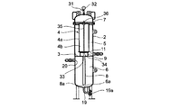
本発明の実施の形態について説明する。図1は本発明の実施の形態を示す正面図、図2は平面図、図3は背面図、図4は図2のA−A線断面図、図5は図2のB−B線部分拡大断面図、図6は回路図である。図に示すように、本発明の逆洗フィルタ1は、筒状の本体(筒状容器)2を仕切板3により、上下に仕切り、上側に筒状のフィルタエレメント4を取付け濾過室5とし、下側を清浄室6としたものである。濾過室5の上部に上蓋7がボルト30で螺着され、濾過室5が閉塞されている。上蓋7には濾過室用コック31が取り付けられ、濾過室5と外気とが開閉可能にされ、また、上蓋に圧力計32が設けられ濾過室圧力が測定可能にされ、フィルタエレメント4の目詰まり状態を知ることができる。濾過室用コックに圧力スイッチや圧力検知器を接続することにより、圧力の自動検知を行いフィルタエレメント4の目詰まり状態を自動検知することができる。この場合圧力計を校正用に用いるとよい。また、単にメンテナンス時等の濾過室の圧抜きに用いてもよい。
Embodiments of the present invention will be described. 1 is a front view showing an embodiment of the present invention, FIG. 2 is a plan view, FIG. 3 is a rear view, FIG. 4 is a cross-sectional view taken along line AA in FIG. 2, and FIG. FIG. 6 is an enlarged sectional view and FIG. 6 is a circuit diagram. As shown in the figure, a backwash filter 1 according to the present invention has a cylindrical main body (cylindrical container) 2 divided vertically by a
図4に示すように、仕切板3の中央部に下方に向かって伸びる濾過管8が両端を開口して設けられ、上側にフィルタエレメント取付座9が設けられている。フィルタエレメント4が取付座9上に置かれ、取付座9には開口穴33が設けられフィルタエレメント4の内側4bと濾過管8とが連通するようにされている。取付座9の中央のねじ穴34に長ボルト35が螺着されダブルナット36でフィルタエレメント4が取付座9に固定されている。フィルタエレメント4は外側4aから内側4bへ液体を通すことにより濾過を行え、逆流も可能な強度を有し、金網等の金属フィルタ、セラミック、高分子化合物材料を用いたフィルタを使用する。
As shown in FIG. 4, a
図1乃至図4及び図6に示すように、濾過室5の下方には、供給口10とドレン口11が対向して設けられている。供給口はダーティタンクからの濾過すべきクーラントが供給される処理液供給接続口12に3方弁13を介して接続されている。3方弁の残りの接続口14は図示しない安全弁を介してダーティタンク側に接続されている。ドレン口11はドレン開閉弁15を介して図示しないダーティタンクに接続されている。
As shown in FIGS. 1 to 4 and 6, a
図5に示すように、濾過室5の上方には、空気供給口16が設けられ、一方が曲がり管17に接続され上蓋7内上方から空気を供給可能にされている。さらに、空気供給口16の他方は空気供給用開閉弁18に接続されている。
As shown in FIG. 5, an
図4、図6に示すように、清浄室6は下部が鏡板で閉塞され、最下部に清浄室ドレン管19が接続され蓋19aにより閉塞されている。清浄室6の鏡板中央部6aと濾過管8の先端開口8aとは濾過管直径の1.5〜3倍離隔している。清浄室6の上方には、清浄液排出口20と逆洗用空気供給口21が直角位置に設けられている。清浄液排出口20は清浄液用開閉弁22を介して、図示しないクリーンタンクへ接続されている。逆洗用空気供給口21は逆洗時空気供給用開閉弁23に接続されている。
As shown in FIGS. 4 and 6, the lower part of the
図1乃至図3及び図6に示すように、本体2の側面に上下方向に蓄圧管40が取付けられている。蓄圧管の下部にはドレン排出バルブ41が設けられ上部にはレデューサ40aが設けられさらにコック42を介して図示しない空気圧源と接続されている。コック42は使用時は常時開とされ蓄圧管内に常時圧力が供給されている。レデューサ40aとコック42との間で空気管43が分岐し、供給用圧力調整弁(減圧弁)44と、制御用圧力調整弁(減圧弁)45に接続されている。
As shown in FIGS. 1 to 3 and 6, a
制御用圧力調整弁45はさらに、制御バルブ46に接続されている。制御バルブ46は別途制御盤47からの電気信号により切り替わり、それぞれ接続された開閉弁を空気圧により開閉するようにされている。
The control
供給用圧力調整弁44はさらに、前述した空気供給用開閉弁18、逆洗時空気供給用開閉弁23に接続され、制御盤、制御バルブからの空気圧制御により、それぞれ濾過室5、清浄室6に空気圧を供給できるようにされている。
The supply
次に本発明の実施の形態による作動について述べる。通常の濾過状態においては、3方弁13は処理液供給接続口12と供給口10とが連通し、清浄液用開閉弁22及びコック42が開とされ、その他は閉とされる。供給された処理液は濾過室5のフィルタエレメント4で濾過され、濾過された清浄液は取付座の開口穴33、濾過管8を通って清浄室6に貯留される。清浄室6より溢れ出た清浄液は清浄液排出口20、清浄液用開閉弁22を通ってクリーンタンクへ戻される。
Next, the operation according to the embodiment of the present invention will be described. In a normal filtration state, the three-
フィルタエレメント4が目詰まりを生じた場合は、逆洗を行う。逆洗を行う場合は、3方弁13は処理液供給接続口12を閉塞し、安全弁側の残りの接続口14と供給口10とを連通させ、ドレン開閉弁15を開、清浄液用開閉弁22を閉、空気供給用開閉弁18を開、コック42はそのまま開とされ、その他は閉のままとされる。空気供給用開閉弁18が開となると、蓄圧管40に蓄圧された空気が供給用圧力調整弁44、空気供給用開閉弁18、濾過室5に供給され、この空気圧により濾過室内の処理液がドレン口11、ドレン開閉弁15を通ってダーティタンクへ戻され、濾過室内から液体が排出される。
When the
次に、空気供給用開閉弁18を閉とし、逆洗時空気供給用開閉弁23を開とする。逆洗時空気供給用開閉弁23が開となると、蓄圧管40に蓄圧された空気が供給用圧力調整弁44、逆洗時空気供給用開閉弁23、清浄室6に供給され、この空気圧により清浄液が押し上げられ、濾過管8、開口穴33、フィルタエレメント4の内側4bから外側4aを通って、フィルタエレメントに付着した屑等を離脱させフィルタエレメントの目詰まりを解消する。濾過室内の液はドレン口11、ドレン開閉弁15を通ってダーティタンクへ戻される。特に、濾過室5内の残留液体が少ないので、濾過室側の抵抗が少ない。このため、非常に効率よく清浄液がフィルタエレメント4を通過逆洗浄することができる。また、蓄圧管40内には高圧大容量で空気が蓄圧されているので、十分な圧力、量の空気を清浄室6に送り込み清浄液を濾過室5に送れるので、フィルタエレメント4の目詰まりを確実、短時間に解消できる。
Next, the air supply opening / closing
より好ましくは、再度濾過室へ処理液を注入し、清浄液を清浄室に送り込み、再度濾過室からの液体の排出、清浄室からの清浄液の供給によりフィルタエレメント4を逆洗するとよい。このように、少なくとも2回逆洗するのが好ましい。なお、濾過室からの液体の排出は逆洗サイクルの短縮に役立つが必ずしも必須ではない。
More preferably, the treatment liquid is again injected into the filtration chamber, the cleaning liquid is sent to the cleaning chamber, and the
また、逆洗タイミングはタイマ等により行うのが制御も簡単で確実である。また、目詰まりの検知や状況等については、圧力計32により判断してもよい。さらに、コック31に取り付けてプレッシャスイッチや圧力検知器、検出器を用いて自動化してもよい。
In addition, it is easy and reliable to control the backwash timing with a timer or the like. In addition, the clogging detection and status may be determined by the
1 逆洗フィルタ。
2 筒状容器(本体)
4 フィルタエレメント
4a フィルタエレメントの外側
4b フィルタエレメントの内側
5 濾過室
6 清浄室
23 逆洗時空気供給用開閉弁
40 蓄圧管
44 圧力調整弁
1 Backwash filter.
2 Tubular container (main body)
4
Claims (1)
前記濾過室及び前記清浄室は、垂直方向に伸びる筒状容器内に上下に隣接して配置形成されており、前記筒状容器の外周の長手方向に沿って管状の蓄圧管が取付けられ、前記蓄圧管は空気圧源と接続可能にされ、かつ、前記蓄圧管と前記清浄室とが圧力調整弁及び逆洗時空気供給用開閉弁を介して連通するようにされていることを特徴とする逆洗フィルタ。 A filtration chamber provided with a cylindrical filter element and configured to filter the treatment liquid; and a clean chamber that primarily stores the cleaning liquid filtered in the filtration chamber, and from the outside of the filter element during normal operation. Pass the processing liquid to the inside, filter the processing liquid, supply the cleaning liquid to the cleaning chamber, discharge the cleaning liquid to the outside, and send air pressure to the cleaning chamber when cleaning the filter element, In the backwashing filter configured to backflow indoor cleaning liquid or air into the filter element, backwash the filter element, and discharge the filter element from the filtration chamber.
The filtration chamber and the clean chamber are arranged adjacent to each other vertically in a cylindrical container extending in the vertical direction, and a tubular accumulator is attached along the longitudinal direction of the outer periphery of the cylindrical container, The pressure accumulating pipe is connectable to an air pressure source, and the pressure accumulating pipe and the clean chamber communicate with each other via a pressure regulating valve and a backwashing air supply opening / closing valve. Wash filter.
Priority Applications (1)
| Application Number | Priority Date | Filing Date | Title |
|---|---|---|---|
| JP2008056012A JP4614370B2 (en) | 2008-03-06 | 2008-03-06 | Backwash filter |
Applications Claiming Priority (1)
| Application Number | Priority Date | Filing Date | Title |
|---|---|---|---|
| JP2008056012A JP4614370B2 (en) | 2008-03-06 | 2008-03-06 | Backwash filter |
Publications (2)
| Publication Number | Publication Date |
|---|---|
| JP2009208036A true JP2009208036A (en) | 2009-09-17 |
| JP4614370B2 JP4614370B2 (en) | 2011-01-19 |
Family
ID=41181709
Family Applications (1)
| Application Number | Title | Priority Date | Filing Date |
|---|---|---|---|
| JP2008056012A Expired - Fee Related JP4614370B2 (en) | 2008-03-06 | 2008-03-06 | Backwash filter |
Country Status (1)
| Country | Link |
|---|---|
| JP (1) | JP4614370B2 (en) |
Cited By (1)
| Publication number | Priority date | Publication date | Assignee | Title |
|---|---|---|---|---|
| JP2013104199A (en) * | 2011-11-11 | 2013-05-30 | Nagaoka International Corp | Intake structure of intake well |
Citations (5)
| Publication number | Priority date | Publication date | Assignee | Title |
|---|---|---|---|---|
| JPS6380814A (en) * | 1986-07-04 | 1988-04-11 | Totoku Electric Co Ltd | Filter apparatus |
| JPH034909A (en) * | 1989-05-30 | 1991-01-10 | Nippon Parkerizing Co Ltd | System for removing sludge in treatment liquid |
| JPH0513508U (en) * | 1991-03-14 | 1993-02-23 | 株式会社エフエスケー | Pressure filtration device |
| JPH05137908A (en) * | 1990-10-16 | 1993-06-01 | Graver Co:The | Method and device for back washing |
| JP2007038205A (en) * | 2005-06-28 | 2007-02-15 | Yamada Tetsuzo | Filtering apparatus |
-
2008
- 2008-03-06 JP JP2008056012A patent/JP4614370B2/en not_active Expired - Fee Related
Patent Citations (5)
| Publication number | Priority date | Publication date | Assignee | Title |
|---|---|---|---|---|
| JPS6380814A (en) * | 1986-07-04 | 1988-04-11 | Totoku Electric Co Ltd | Filter apparatus |
| JPH034909A (en) * | 1989-05-30 | 1991-01-10 | Nippon Parkerizing Co Ltd | System for removing sludge in treatment liquid |
| JPH05137908A (en) * | 1990-10-16 | 1993-06-01 | Graver Co:The | Method and device for back washing |
| JPH0513508U (en) * | 1991-03-14 | 1993-02-23 | 株式会社エフエスケー | Pressure filtration device |
| JP2007038205A (en) * | 2005-06-28 | 2007-02-15 | Yamada Tetsuzo | Filtering apparatus |
Cited By (1)
| Publication number | Priority date | Publication date | Assignee | Title |
|---|---|---|---|---|
| JP2013104199A (en) * | 2011-11-11 | 2013-05-30 | Nagaoka International Corp | Intake structure of intake well |
Also Published As
| Publication number | Publication date |
|---|---|
| JP4614370B2 (en) | 2011-01-19 |
Similar Documents
| Publication | Publication Date | Title |
|---|---|---|
| KR20140023680A (en) | Multi-cage type ballast water filter equipment auto-controlling simultaneously back-washing and method thereof | |
| JP2007038205A (en) | Filtering apparatus | |
| KR20160005319A (en) | Water Purifier Capable of Reducing Water Consumption | |
| RU2008139806A (en) | FILTER DEVICE AND FILTRATION METHOD | |
| DK2756874T3 (en) | A filter device | |
| KR200475293Y1 (en) | filter type sample pretreatment system using high pressure air | |
| RU2317841C9 (en) | Device for filtering food liquids, mainly milk | |
| KR101135951B1 (en) | Cleaning Method of Water Purifier | |
| CN209752297U (en) | Reverse flow back-flushing filter | |
| JP4614370B2 (en) | Backwash filter | |
| JP5768391B2 (en) | Filtration device | |
| JP2008284464A (en) | Filtering method and apparatus therefor with excellent intermittent backwashing | |
| KR100314211B1 (en) | Chip filter apparatus of cutting oil and method thereof | |
| CN215249730U (en) | Water purifying device | |
| KR100884643B1 (en) | Measuring Apparatus of Filter Exchange Period in A Water Purifier | |
| WO2014054086A1 (en) | Fluid purification device | |
| CN210356240U (en) | Lathe cutting fluid filter equipment | |
| RU53585U1 (en) | DEVICE FOR FILTRATION OF FOOD LIQUIDS, PREVIOUSLY OF MILK | |
| KR20090106961A (en) | Self-cleaning filter system | |
| TW452519B (en) | Multi-class filteration device | |
| JP5773259B2 (en) | Faucet mounted water purifier | |
| CN205569937U (en) | Large capacity easily washes water filter | |
| EP0542092B1 (en) | Device for separating solid particles from waste water in a dental apparatus | |
| JP2011011266A (en) | Apparatus for purifying coolant | |
| KR101394229B1 (en) | Multi-cage type ballast water filter equipment having discharge pipe which can be attached and detached |
Legal Events
| Date | Code | Title | Description |
|---|---|---|---|
| RD02 | Notification of acceptance of power of attorney |
Free format text: JAPANESE INTERMEDIATE CODE: A7422 Effective date: 20100507 |
|
| A977 | Report on retrieval |
Free format text: JAPANESE INTERMEDIATE CODE: A971007 Effective date: 20100628 |
|
| A131 | Notification of reasons for refusal |
Free format text: JAPANESE INTERMEDIATE CODE: A131 Effective date: 20100727 |
|
| A521 | Request for written amendment filed |
Free format text: JAPANESE INTERMEDIATE CODE: A523 Effective date: 20100818 |
|
| TRDD | Decision of grant or rejection written | ||
| A01 | Written decision to grant a patent or to grant a registration (utility model) |
Free format text: JAPANESE INTERMEDIATE CODE: A01 Effective date: 20101005 |
|
| A01 | Written decision to grant a patent or to grant a registration (utility model) |
Free format text: JAPANESE INTERMEDIATE CODE: A01 |
|
| A61 | First payment of annual fees (during grant procedure) |
Free format text: JAPANESE INTERMEDIATE CODE: A61 Effective date: 20101015 |
|
| R150 | Certificate of patent or registration of utility model |
Ref document number: 4614370 Country of ref document: JP Free format text: JAPANESE INTERMEDIATE CODE: R150 Free format text: JAPANESE INTERMEDIATE CODE: R150 |
|
| FPAY | Renewal fee payment (event date is renewal date of database) |
Free format text: PAYMENT UNTIL: 20131029 Year of fee payment: 3 |
|
| S531 | Written request for registration of change of domicile |
Free format text: JAPANESE INTERMEDIATE CODE: R313531 |
|
| R350 | Written notification of registration of transfer |
Free format text: JAPANESE INTERMEDIATE CODE: R350 |
|
| LAPS | Cancellation because of no payment of annual fees |