JP2009201343A - Permanent magnet rotating electrical machine - Google Patents
Permanent magnet rotating electrical machine Download PDFInfo
- Publication number
- JP2009201343A JP2009201343A JP2008129530A JP2008129530A JP2009201343A JP 2009201343 A JP2009201343 A JP 2009201343A JP 2008129530 A JP2008129530 A JP 2008129530A JP 2008129530 A JP2008129530 A JP 2008129530A JP 2009201343 A JP2009201343 A JP 2009201343A
- Authority
- JP
- Japan
- Prior art keywords
- permanent magnet
- array
- rotor
- stator
- permanent
- Prior art date
- Legal status (The legal status is an assumption and is not a legal conclusion. Google has not performed a legal analysis and makes no representation as to the accuracy of the status listed.)
- Pending
Links
Images


Abstract
Description
本発明は、電機子巻線を有する固定子に対し回転可能に支持された回転子にハルバッハ配列された永久磁石を有する永久磁石回転電機に関する。 The present invention relates to a permanent magnet rotating electric machine having permanent magnets arranged in a Halbach array on a rotor that is rotatably supported by a stator having an armature winding.
永久磁石をハルバッハ配列した永久磁石回転電機は、径方向にN極とS極とを交互に配置した主磁極磁石と、この主磁極磁石の周方向両面に径方向以外(例えば周方向)に着磁された補助磁石を備えたものである(例えば、特許文献1、2参照)。永久磁石をハルバッハ配列した永久磁石回転電機の主磁極磁石と補助磁石とは、全体で略円筒状をなしており、永久磁石をハルバッハ配列にすると、特定の方向の磁力を強めることができる。このハルバッハ配列された永久磁石を有する回転電機は、大きくすることなく高出力化を図ることが可能になる。
A permanent magnet rotating electrical machine in which permanent magnets are arranged in a Halbach arrangement is provided with a main magnetic pole magnet in which N poles and S poles are alternately arranged in the radial direction and on both sides of the main magnetic pole magnet in a direction other than the radial direction (for example, in the circumferential direction). It is provided with a magnetized auxiliary magnet (see, for example,
図18は、従来のハルバッハ配列した永久磁石列を有する回転電機の磁束密度分布を示した磁束密度分布図である。ヨーク鉄心15に電機子巻線4が巻かれており、永久磁石16、電機子巻線4、ヨーク鉄心15の間に磁束が形成される。
しかし、特許文献1のものでは、固定子や回転子に鉄心を用いているため回転電機の質量が重くなり、高出力を図るには、回転電機の軸方向若しくは径方向に長くする必要がある。また、特許文献2のものにおいても、固定子に鉄心を用いているため回転電機の質量が重くなり、高出力を図るには、回転電機の軸方向若しくは径方向に長くする必要がある。
However, in the thing of
本発明の目的は、回転電機の形状を軸方向に薄くし軽量化を図り、しかも高出力が得られる永久磁石回転電機を提供することである。 An object of the present invention is to provide a permanent magnet rotating electrical machine that can reduce the weight by reducing the shape of the rotating electrical machine in the axial direction and can obtain a high output.
本発明の永久磁石回転電機は、電機子巻線を有する固定子と、前記固定子に対し回転可能に支持されハルバッハ配列された永久磁石を有する回転子とからなる永久磁石回転電機において、前記回転子の回転中心から周方向にハルバッハ配列された2列の永久磁石列を設け、前記永久磁石列の間に前記固定子の電機子巻線を設け、前記永久磁石列は、永久磁石列の外側永久磁石の磁極の向きと永久磁石列の内側永久磁石の磁極の向きとが、径方向の磁極の向きについては同一方向で、周方向の磁極向きについては逆方向に向いていることを特徴とする。 The permanent magnet rotating electrical machine of the present invention is a permanent magnet rotating electrical machine comprising a stator having armature windings and a rotor having permanent magnets supported rotatably with respect to the stator and arranged in a Halbach array. Two rows of permanent magnets arranged in Halbach in the circumferential direction from the center of rotation of the child are provided, and the armature winding of the stator is provided between the permanent magnet rows, and the permanent magnet row is arranged outside the permanent magnet row. The direction of the magnetic poles of the permanent magnets and the direction of the magnetic poles of the inner permanent magnets of the permanent magnet array are the same in the direction of the radial magnetic poles, and are opposite in the direction of the magnetic poles in the circumferential direction. To do.
回転子にハルバッハ配列された永久磁石列は、外側に配置した永久磁石列が内側に配置した永久磁石列より径方向に長く、または、内側に配置した永久磁石列が外側に配置した永久磁石列より径方向に長く形成される。 The permanent magnet row arranged on the rotor in Halbach is longer in the radial direction than the permanent magnet row arranged on the outer side, or the permanent magnet row arranged on the outer side. It is formed longer in the radial direction.
ハルバッハ配列された永久磁石列を配置した回転子は、非磁性金属部材または樹脂部材で形成される。また、固定子は、非磁性金属部材または樹脂部材で形成される。さらに、固定子に配置した電機子巻線は、集中巻きの巻線またはプリント基板で形成される。また、固定子に配置した電機子巻線は、その電機子巻線に対向する永久磁石面の幅より広く形成される。 The rotor having the permanent magnet array arranged in Halbach is formed of a nonmagnetic metal member or a resin member. The stator is formed of a nonmagnetic metal member or a resin member. Furthermore, the armature windings arranged on the stator are formed by concentrated windings or printed boards. Further, the armature winding disposed on the stator is formed wider than the width of the permanent magnet surface facing the armature winding.
固定子に配置した電機子巻線は、炭素線、超電導線または高温超電導線のいずれかを用いる。外側に配置したハルバッハ配列の永久磁石列の外側、または内側に配置したハルバッハ配列の永久磁石列の内側、または外側に配置したハルバッハ配列の永久磁石列の外側及び内側に配置したハルバッハ配列の永久磁石列の内側の双方に強磁性部材を備える。 As the armature winding arranged on the stator, any one of a carbon wire, a superconducting wire, and a high-temperature superconducting wire is used. The permanent magnets of the Halbach array arranged outside and inside the permanent magnet rows of the Halbach array arranged on the outside or inside of the permanent magnet array of the Halbach arrangement arranged on the outside or inside the permanent magnet array of the Halbach arrangement arranged on the outside. Ferromagnetic members are provided on both inside rows.
回転子に配置された永久磁石列は、回転子の周方向または軸方向に非磁性部材で構成された永久磁石押さえ機構で保持され、または永久磁石を非磁性部材で形成されたケースに収納して保持される。回転子に配置された永久磁石列の永久磁石押さえ機構は、帯状の板、または、ワイヤーで構成される。 The permanent magnet array arranged on the rotor is held by a permanent magnet pressing mechanism made of a nonmagnetic member in the circumferential direction or the axial direction of the rotor, or the permanent magnet is stored in a case formed of a nonmagnetic member. Held. The permanent magnet holding mechanism of the permanent magnet row arranged on the rotor is constituted by a belt-like plate or a wire.
電機子巻線は、非磁性部材で形成された巻線の巻取り部材に集中巻きされ、集中巻きされた巻取り部材ごと固定子に取付けられる構造である。また、巻線の巻取り部材に集中巻きされた巻線は、集中巻きされた巻取り部材ごと樹脂で含浸し、固定子に固定する構造である。 The armature winding has a structure in which concentrated winding is performed on a winding member formed of a nonmagnetic member, and the concentrated winding member is attached to the stator. In addition, the winding wound around the winding member of the winding has a structure in which the concentrated winding member is impregnated with resin and fixed to the stator.
永久磁石列の永久磁石は、希土類磁石(例えばネオジム磁石)で形成されていること、または、ネオジム磁石の中にジスプロシウムを添加させたもので形成されている。永久磁石列の個々の永久磁石は、磁極の向きが周方向に向いた磁石と磁極の向きが径方向に向いた磁石とを別々に回転子に取付ける。磁極の向きが周方向に向いた永久磁石を回転子に取付ける場合、磁極の向きが径方向に向いた永久磁石を取付ける位置に非磁性部材で形成された磁石取付けサポートを用い、磁石取付けサポートをガイドに永久磁石を取付ける。 The permanent magnets of the permanent magnet array are formed of rare earth magnets (for example, neodymium magnets), or are formed by adding dysprosium to neodymium magnets. The individual permanent magnets of the permanent magnet array are each attached to the rotor with a magnet whose magnetic pole is oriented in the circumferential direction and a magnet whose magnetic pole is oriented in the radial direction separately. When mounting a permanent magnet with the magnetic pole facing in the circumferential direction on the rotor, use a magnet mounting support formed of a non-magnetic member at the position where the permanent magnet with the magnetic pole facing in the radial direction is installed. Attach a permanent magnet to the guide.
本発明によれば、回転電機の形状を軸方向に薄くし軽量化を図り、しかも高出力が得られる永久磁石回転電機を提供できる。 According to the present invention, it is possible to provide a permanent magnet rotating electrical machine that can reduce the weight by reducing the shape of the rotating electrical machine in the axial direction and can obtain a high output.
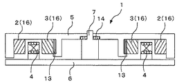
図1は本発明の実施の形態に係わる永久磁石回転電機の一例の軸方向断面図である。永久磁石回転電機1は、固定子6に電機子巻線4及びとシャフト7が形成され、回転子5に永久磁石列2、3及び軸受14が形成されて構成される。
FIG. 1 is an axial sectional view of an example of a permanent magnet rotating electrical machine according to an embodiment of the present invention. The permanent magnet rotating
固定子6には、中心にシャフト7と電機子巻線4を取付けるための凸部とが形成されている。電機子巻線4は、例えば三相交流を用いる場合、U相−V相−W相の順に巻かれている。固定子6と回転子5との間には、軸受14が構成されており、回転子5は固定子6の上で回転する構造になっている。回転子5にはハルバッハの配列で構成された略円筒形状の2列の永久磁石列2、3が周方向に設けられている。回転子5は、固定子6に対向する側に凸部を2列有し、回転子5の外側の凸部には永久磁石列(外側)2の永久磁石16を、内側の凸部には永久磁石列(内側)3の永久磁石16が例えば接着等により取付けられている。そして、回転子5に取り付けられた永久磁石列2、3の間に電機子巻線4を配置するように構成されている。
The
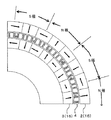
図2は、本発明の実施の形態の永久磁石回転電機の一例の径方向断面図である。回転子5に取り付けられた永久磁石列2,3は、図2に示すような磁極の配列とする。つまり、径方向に着磁された磁極については、外側の永久磁石列2の磁極と内側の永久磁石列3の永久磁石の磁極とが同一方向になるように構成する。径方向に着磁された磁極の間にある周方向に着磁された永久磁石については、外側の永久磁石列2の磁極と内側の永久磁石列3の磁極とが反対方向になるように構成する。
FIG. 2 is a radial cross-sectional view of an example of the permanent magnet rotating electric machine according to the embodiment of the present invention. The
次に、図3は本発明の実施の形態に係わる永久磁石回転電機の磁束密度分布の一例を示す磁束密度分布図、図4は本発明の実施の形態に係わる永久磁石回転電機の磁力線分布の一例を示す磁力線分布図である。 Next, FIG. 3 is a magnetic flux density distribution diagram showing an example of the magnetic flux density distribution of the permanent magnet rotating electric machine according to the embodiment of the present invention, and FIG. 4 is a diagram of the magnetic force line distribution of the permanent magnet rotating electric machine according to the embodiment of the present invention. It is a magnetic force line distribution map which shows an example.
図3に示すように、永久磁石列2、3の磁束が電機子巻線4を鎖交する様子が分かる。電機子巻線4に例えば三相交流を流すことで回転子5が回転する。図3及び図4から分かるように、径方向に着磁された永久磁石に多くの磁束が発生していることが分かる。つまり、電機子巻線4に鎖交することにより大きなトルクを得ることが可能になる。周方向に着磁された永久磁石の磁束は、外側の永久磁石列2と内側の永久磁石列3とでは反対の向きになり、互いの磁束をキャンセルする働きをする。径方向の磁束密度分布について、従来例の図18と対比すると、図3の磁束密度分布は、図18の磁束密度分布に比べ約2倍の磁束が得られることが分かる。また、図18ではヨーク鉄心15に電機子巻線4を巻いた結果であり、質量増大の要因になっている。
As shown in FIG. 3, it can be seen that the magnetic fluxes of the
このように、回転子5にハルバッハ配列した略円筒形状の2列の永久磁石列2、3を設け、略円筒形状の永久磁石列2、3の間に固定子6の電機子巻線4を設けることで、永久磁石回転電機1の軸方向の幅を薄くすることができる。また、ハルバッハ配列した略円筒形状の永久磁石列を2列構成することで、従来例に比べ磁束密度が大きいことから、永久磁石回転電機の形状を大きくすることなく高出力化が可能になる。
In this way, the
図5は本発明の実施の形態に係わる永久磁石回転電機の他の一例の軸方向断面図である。この図5に示した一例は、図1に示した一例に対し、回転子5にハルバッハ配列した略円筒形状の永久磁石列2、3において、外側の永久磁石列2の径方向の寸法を内側の永久磁石列3の径方向の寸法より長くしたものである。図1と同一要素には同一符号を付し重複する説明は省略する。
FIG. 5 is an axial sectional view of another example of the permanent magnet rotating electrical machine according to the embodiment of the present invention. The example shown in FIG. 5 differs from the example shown in FIG. 1 in that the radial dimension of the outer
外側の永久磁石列2の径方向の寸法を内側の永久磁石列3の径方向の寸法より長くしたことで、外側の永久磁石列2の永久磁石16の磁束密度を大きくできるため、回転電機の出力(トルク)を大きくすることができる。
Since the radial dimension of the outer
図6は本発明の実施の形態に係わる永久磁石回転電機の別の他の一例の軸方向断面図である。この図6に示した一例は、図1に示した一例に対し、回転子5にハルバッハ配列した略円筒形状の永久磁石列2、3の永久磁石16の体積をほぼ同じになるように内側の永久磁石列3の径方向の寸法を外側の永久磁石列2の径方向の寸法より長くしたものである。図1と同一要素には同一符号を付し重複する説明は省略する。
FIG. 6 is an axial sectional view of another example of the permanent magnet rotating electrical machine according to the embodiment of the present invention. The example shown in FIG. 6 is different from the example shown in FIG. 1 in that the volume of the
回転子5にハルバッハ配列した略円筒形状の永久磁石列2、3の体積をほぼ同じになるようにしたことで、それぞれの永久磁石列2、3のエネルギー密度がほぼ同じになり、電機子巻線4を鎖交する磁束が均一化される。これにより、大きい出力(トルク)を得ることができる。
By making the volumes of the substantially cylindrical
次に、ハルバッハ配列された永久磁石列2、3を配置した回転子5は、非磁性金属部材や樹脂部材で形成される。一般的には回転子5は薄い電磁鋼板を積層して構成されるが、加工が容易な非磁性金属部材や樹脂部材とし、回転子5への永久磁石列2、3の取付けを容易にし、さらに軽量化を図るとともに製造コストを削減する。
Next, the
また、電機子巻線4を配置した固定子6についても、非磁性金属部材または樹脂部材で形成する。一般的には固定子6は回転子5と同様に薄い電磁鋼板を積層して構成されるが、加工が容易な非磁性金属部材や樹脂部材とし、軽量化を図るとともに製造コストを削減する。
The
次に、固定子6に配置した電機子巻線4は、集中巻きの巻線またはプリント基板で形成する。図7は、電機子巻線4を集中巻きで形成した場合の永久磁石回転電機の一部切欠径方向断面図である。図7に示すように、電機子巻線4を集中巻にすることで、巻線を永久磁石列2と永久磁石列3との間に収めることが可能になる。これにより永久磁石回転電機1は電機子巻線4が軸方向に広がらない。また、永久磁石回転電機1の軸方向の長さを薄くすることができる。さらに、予めボビン(図示省略)に電機子巻線4を巻いて置き、固定子6に装着することができるので、製造コストを削減することができる。
Next, the armature winding 4 disposed on the
図8は、電機子巻線4をプリント基板で形成した場合の永久磁石回転電機の軸方向断面図である。図8に示すように、電機子巻線4をプリント基板11で形成しているので、従来例で用いられる銅線に比べ軽量化することができる。従って、永久磁石回転電機の小型化や軽量化が図れる。
FIG. 8 is an axial cross-sectional view of a permanent magnet rotating electrical machine when the armature winding 4 is formed of a printed board. As shown in FIG. 8, since the armature winding 4 is formed of the printed
また、固定子6に配置した電機子巻線4は、その電機子巻線に対向する永久磁石面の幅より広く形成してもよい。図9は、電機子巻線4をそれに対向する永久磁石面の幅より広く形成した場合の永久磁石回転電機の軸方向断面図である。図9に示すように、電機子巻線4の軸方向長さを対向する永久磁石列2、3面の幅より長く(広く)形成している。電機子巻線4の軸方向長さを対向する永久磁石列2、3面の幅より長く(広く)したことで、電機子巻線4に対し、永久磁石列2、3の磁界が鎖交する量を多くすることができ、永久磁石列2、3の磁束を効率よく得ることができる。従って、永久磁石回転電機1の高出力化が図れる。
Further, the armature winding 4 disposed on the
さらに、固定子6に配置した電機子巻線4は、炭素線、超電導線または高温超電導線のいずれかを用いて形成する。電機子巻線4の巻線材料に炭素線を用いた場合には、従来例で用いられる銅線に比べ軽量化することができるため、永久磁石回転電機の軽量化が図れる。図10は電機子巻線4に超電導線もしくは高温超電導線を用いた場合の永久磁石回転電機の軸方向断面図である。図10に示すように、超電導線または高温超電導線の電機子巻線は、クライオ8の中に配置されており、クライオ8には低温配管9が接続されている。低温配管9の端部は冷凍機10に接続され、冷凍機10を駆動することでクライオ8の内部が超電導状態を維持できる構成になっている。電機子巻線4の巻線材料に超電導線もしくは高温超電導線を用いていることで、電機子巻線4の電気抵抗をゼロにでき、電流の損失をなくすことができ、永久磁石回転電機の高出力化が図れる。
Further, the armature winding 4 disposed on the
次に、ハルバッハ配列の永久磁石列に漏れ磁束を減少させるための強磁性部材を設けるようにしてもよい。図11は外側に配置したハルバッハ配列の永久磁石列2の外側に強磁性部材12を備えた場合の永久磁石回転電機の軸方向断面図である。図11に示すように、外側に配置したハルバッハ配列の永久磁石列2の外側に強磁性部材12が設けられている。
Next, a ferromagnetic member for reducing leakage magnetic flux may be provided in the permanent magnet array in the Halbach array. FIG. 11 is a sectional view in the axial direction of a permanent magnet rotating electrical machine when the
図12は内側に配置したハルバッハ配列の永久磁石列3の内側に強磁性部材13を備えた場合の永久磁石回転電機の軸方向断面図である。図12に示すように、内側に配置したハルバッハ配列の永久磁石列3の内側に強磁性部材13が設けられている。
FIG. 12 is a sectional view in the axial direction of a permanent magnet rotating electrical machine when the
また、図13は外側に配置したハルバッハ配列の永久磁石列2の外側及び内側に配置したハルバッハ配列の永久磁石列3の内側の双方に強磁性部材12、13を備えた場合の永久磁石回転電機の軸方向断面図である。図13に示すように、外側に配置したハルバッハ配列の永久磁石列2の外側、及び内側に配置したハルバッハ配列の永久磁石列3の内側の双方に強磁性部材12、13が設けられている。強磁性部材12、13及び永久磁石列2、3は、例えば接着により回転子5に接続されている。
FIG. 13 shows a permanent magnet rotating electrical machine in which
図3に示す磁束密度分布では、外側の永久磁石列2の径方向外側と、内側の永久磁石列2の径方向内側とに、若干ではあるが磁束が発生していることが分かる。つまり、若干ではあるが、漏れ磁束が生じている。そこで、外側強磁性部材12と内側強磁性部材13とを永久磁石列2、3に取付けることで、漏れ磁束は強磁性部材12、13を経由するため、磁束の漏れを減少させることができる。漏れ磁束が減少すれば永久磁石列2、3と電機子巻線4間のギャップ中の磁束を増やすことができる。これにより、漏れ磁束が減少し、ギャップ中の磁束が増加するので、永久磁石回転電機の高出力化が図れる。
In the magnetic flux density distribution shown in FIG. 3, it can be seen that a small amount of magnetic flux is generated on the radially outer side of the outer
次に、永久磁石列2、3が回転による遠心力で回転子5から剥がれを防止するため非磁性部材で形成した永久磁石押さえ機構17を設けてもよい。図14はハルバッハ配列の永久磁石列2、3の永久磁石16に非磁性部材で形成した永久磁石押さえ機構17を備えた場合の永久磁石回転電機の軸方向断面図である。図14に示すように、ハルバッハ配列の永久磁石列2、3の永久磁石16は非磁性部材で形成した永久磁石押さえ機構17により回転子5に保持されている。永久磁石押さえ機構17は、例えば、非磁性部材で形成された帯状の板もしくはワイヤーで構成されている。これにより、永久磁石回転電機1が回転中に永久磁石16が回転子5から剥がれたりすることを防止でき安定的に高出力が得られる。
Next, a permanent magnet
次に、永久磁石列2、3の永久磁石16は、非磁性部材で形成されたケース18の中に収められてもよい。図15はハルバッハ配列の永久磁石列2、3の永久磁石16が非磁性部材で形成されたケース18の中に収められた場合の永久磁石回転電機の軸方向断面図である。図15に示すように、ハルバッハ配列の永久磁石列2、3が非磁性部材で形成されたケース18の中に収められている。ケースは回転子5に取り付けられている。この場合、永久磁石16をケース18に挿入して製造することから製造コストの低減が図れる。さらに、ケース18を容易に回転子5に取付けられるため製造コストの低減が図れる。
Next, the
次に、電機子巻線4は、非磁性部材で形成された巻線の巻取り部材19に集中巻きされ、集中巻きされた巻取り部材19ごと固定子6に取付けられるようにしてもよい。図16は永久磁石列2、3の永久磁石16と巻線の巻取り部材19の配置の一例を示した永久磁石回転電機の径方向断面図である。予め電機子巻線4を非磁性部材で形成された巻取り部材19に集中巻きし、その後、固定子6に取付けることで製造が容易になり、製造コストの低減が図れる。
Next, the armature winding 4 may be concentratedly wound around a winding
また、集中巻きされた複数の電機子巻線4は、樹脂で含浸して一体化してもよい。一体化することで取扱いを容易にできるとともに、固定子6への固定も容易にできる。
The plurality of
次に、永久磁石列2、3の永久磁石16は、希土類磁石(例えばネオジム磁石)で形成してもよい。または、ネオジム磁石の中にジスプロシウムを添加させたもので形成してもよい。永久磁石に希土類磁石を用いることで磁力が増し、高出力を得ることができる。さらにジスプロシウムはネオジム磁石の磁力を高める働きがあり、ネオジム磁石の中にジスプロシウムを添加した永久磁石16を用いることで高出力化が図れる。
Next, the
次に、永久磁石列2、3の個々の永久磁石16は、磁極の向きが周方向に向いた磁石と磁極の向きが径方向に向いた磁石を別々に回転子5に取付ける製造方法としてもよい。一例として回転子5に永久磁石16の磁極の向きが周方向の永久磁石16を接着等により取付ける。そして、周方向の永久磁石16が回転子5に取付いた後、径方向の永久磁石16を接着等により取付ける。この製造方法によれば、隣接する永久磁石16の磁力の影響を受けることなく永久磁石16を回転子5に取付けることができ、製造コストの削減が図れる。
Next, the individual
また、一例として、磁極の向きが周方向に向いた永久磁石16を回転子5に取付ける場合、磁極の向きが径方向に向いた永久磁石16を取付ける位置に非磁性部材で形成された磁石取付けサポート20、21を備え、磁石取付けサポート20、21をガイドに永久磁石16を取付ける製造方法としてもよい。図17は永久磁石16を回転子5に取付けるための磁石取付けサポート20、21の一例を示した永久磁石回転電機の径方向断面図である。磁石取付けサポート20、21をガイドに永久磁石16を取付ける製造方法を用いることで隣接する永久磁石16の磁力の影響を受けることなく、容易に永久磁石16を回転子5に取付けることができ、製造コストの削減が図れる。
Further, as an example, when the
本発明の実施の形態によれば、永久磁石回転電機の回転子5と固定子6に鉄心を用いないので軽量化が図れる。ハルバッハ配列された略円筒形状の永久磁石を2列配置し、その永久磁石2、3の間に電機子巻線4を配置するので軸方向の幅を薄くすることができる。また、ハルバッハ配列された略円筒形状の永久磁石を2列配置し、効率の良い磁束密度分布にしたことで高出力化が図れる。回転子5と固定子6に鉄心を用いないので、製造が容易になり製造コストを低減することができる。
According to the embodiment of the present invention, an iron core is not used for the
1…永久磁石回転電機、2…永久磁石(外側)、3…永久磁石(内側)、4…電機子巻線、5…回転子、6…固定子、7…シャフト、8…クライオ、9…低温配管、10…冷凍機、11…プリント基板、12…強磁性部材(外側)、13…強磁性部材(内側)、14…軸受、15…ヨーク鉄心、16…永久磁石、17…永久磁石押さえ機構、18…ケース、19…巻線の巻取り部材、20…永久磁石取付けサポート(外側)、21…永久磁石取付けサポート(内側)
DESCRIPTION OF
Claims (6)
Priority Applications (1)
| Application Number | Priority Date | Filing Date | Title |
|---|---|---|---|
| JP2008129530A JP2009201343A (en) | 2008-01-23 | 2008-05-16 | Permanent magnet rotating electrical machine |
Applications Claiming Priority (2)
| Application Number | Priority Date | Filing Date | Title |
|---|---|---|---|
| JP2008012847 | 2008-01-23 | ||
| JP2008129530A JP2009201343A (en) | 2008-01-23 | 2008-05-16 | Permanent magnet rotating electrical machine |
Publications (1)
| Publication Number | Publication Date |
|---|---|
| JP2009201343A true JP2009201343A (en) | 2009-09-03 |
Family
ID=41144248
Family Applications (1)
| Application Number | Title | Priority Date | Filing Date |
|---|---|---|---|
| JP2008129530A Pending JP2009201343A (en) | 2008-01-23 | 2008-05-16 | Permanent magnet rotating electrical machine |
Country Status (1)
| Country | Link |
|---|---|
| JP (1) | JP2009201343A (en) |
Cited By (14)
| Publication number | Priority date | Publication date | Assignee | Title |
|---|---|---|---|---|
| WO2011045842A1 (en) * | 2009-10-15 | 2011-04-21 | 株式会社 東芝 | Permanent magnet dynamo-electric machine |
| JP2012010466A (en) * | 2010-06-23 | 2012-01-12 | Toshiba Corp | Rotating electrical machine |
| JP2012010565A (en) * | 2010-06-28 | 2012-01-12 | Toshiba Corp | Permanent magnet rotary electric machine |
| JP2012019605A (en) * | 2010-07-07 | 2012-01-26 | Toshiba Corp | Permanent magnet rotating electrical machine |
| JP2012175755A (en) * | 2011-02-18 | 2012-09-10 | Toshiba Corp | Permanent magnet rotary electric machine |
| WO2015173734A1 (en) * | 2014-05-12 | 2015-11-19 | Stellenbosch University | Radial flux permanent magnet machine |
| KR20160091057A (en) | 2015-01-23 | 2016-08-02 | 에이텍 코퍼레이션 | Electromagnetic induction apparatus |
| CN106246784A (en) * | 2016-09-27 | 2016-12-21 | 北京理工大学 | A kind of eddy-current damping magnetic spring based on multiple halbach permanent magnet arrays |
| CN108988530A (en) * | 2018-07-25 | 2018-12-11 | 中山市特斯拉克磁电科技有限公司 | Improve the method and its magnetic shoe rotor combining structure of magnetic element magnetic field utilization rate |
| EP2451059B1 (en) * | 2010-11-04 | 2019-01-23 | Xap | Brushless electromagnetic motor. |
| JP2020137387A (en) * | 2019-02-26 | 2020-08-31 | 橘コンサルタンツ株式会社 | Rotary motor and linear motor |
| WO2021054472A1 (en) * | 2019-09-20 | 2021-03-25 | 学校法人工学院大学 | Magnetic field generating device, and rotating electrical machine |
| US11239715B2 (en) | 2017-08-30 | 2022-02-01 | Kogakuin University | Electromagnetic device |
| JP7468753B1 (en) | 2023-05-24 | 2024-04-16 | 富士電機株式会社 | Encoder |
-
2008
- 2008-05-16 JP JP2008129530A patent/JP2009201343A/en active Pending
Cited By (16)
| Publication number | Priority date | Publication date | Assignee | Title |
|---|---|---|---|---|
| WO2011045842A1 (en) * | 2009-10-15 | 2011-04-21 | 株式会社 東芝 | Permanent magnet dynamo-electric machine |
| JP2012010466A (en) * | 2010-06-23 | 2012-01-12 | Toshiba Corp | Rotating electrical machine |
| JP2012010565A (en) * | 2010-06-28 | 2012-01-12 | Toshiba Corp | Permanent magnet rotary electric machine |
| JP2012019605A (en) * | 2010-07-07 | 2012-01-26 | Toshiba Corp | Permanent magnet rotating electrical machine |
| EP2451059B1 (en) * | 2010-11-04 | 2019-01-23 | Xap | Brushless electromagnetic motor. |
| JP2012175755A (en) * | 2011-02-18 | 2012-09-10 | Toshiba Corp | Permanent magnet rotary electric machine |
| WO2015173734A1 (en) * | 2014-05-12 | 2015-11-19 | Stellenbosch University | Radial flux permanent magnet machine |
| KR20160091057A (en) | 2015-01-23 | 2016-08-02 | 에이텍 코퍼레이션 | Electromagnetic induction apparatus |
| CN106246784A (en) * | 2016-09-27 | 2016-12-21 | 北京理工大学 | A kind of eddy-current damping magnetic spring based on multiple halbach permanent magnet arrays |
| US11239715B2 (en) | 2017-08-30 | 2022-02-01 | Kogakuin University | Electromagnetic device |
| CN108988530A (en) * | 2018-07-25 | 2018-12-11 | 中山市特斯拉克磁电科技有限公司 | Improve the method and its magnetic shoe rotor combining structure of magnetic element magnetic field utilization rate |
| JP2020137387A (en) * | 2019-02-26 | 2020-08-31 | 橘コンサルタンツ株式会社 | Rotary motor and linear motor |
| JP7372640B2 (en) | 2019-02-26 | 2023-11-01 | 橘コンサルタンツ株式会社 | Rotary motor and linear motor |
| WO2021054472A1 (en) * | 2019-09-20 | 2021-03-25 | 学校法人工学院大学 | Magnetic field generating device, and rotating electrical machine |
| JPWO2021054472A1 (en) * | 2019-09-20 | 2021-03-25 | ||
| JP7468753B1 (en) | 2023-05-24 | 2024-04-16 | 富士電機株式会社 | Encoder |
Similar Documents
| Publication | Publication Date | Title |
|---|---|---|
| JP2009201343A (en) | Permanent magnet rotating electrical machine | |
| JP5491484B2 (en) | Switched reluctance motor | |
| US8643240B2 (en) | Superconducting rotating electrical machine and stator for use with superconducting rotating electrical machine | |
| JP5576246B2 (en) | Axial gap type brushless motor | |
| JP2010110128A (en) | Permanent magnet rotating electrical machine | |
| US20130026864A1 (en) | Traversal switched reluctance motor | |
| US20110163618A1 (en) | Rotating Electrical Machine | |
| JP2009540788A (en) | Ring coil motor | |
| US9356479B2 (en) | Hybrid excitation rotating electrical machine | |
| KR101263350B1 (en) | axial flux permanent magnet generator | |
| JP4758703B2 (en) | Superconducting device and axial gap type superconducting motor | |
| JP2011078202A (en) | Axial gap motor | |
| JP2010004634A (en) | Axial-gap type rotating electrical machine | |
| WO2018193969A1 (en) | Dynamo-electric machine | |
| JP2008035639A (en) | Motor | |
| JP2010284035A (en) | Permanent magnet rotating electrical machine | |
| JP2006166679A (en) | Structure of stator for axial gap type dynamo-electric machine | |
| WO2011045842A1 (en) | Permanent magnet dynamo-electric machine | |
| JP2012019605A (en) | Permanent magnet rotating electrical machine | |
| JP2010284036A (en) | Permanent magnet rotating electrical machine | |
| JP7259798B2 (en) | axial gap motor | |
| JP2016129447A (en) | Rotary electric machine | |
| JP2008187863A (en) | Axial gap rotary electric machine and compressor | |
| WO2021210119A1 (en) | Magnetic-geared motor | |
| JP5894414B2 (en) | Generator |