JP2009168564A - Overflow prevention device, overflow prevention method, and pool reconstruction method - Google Patents

Overflow prevention device, overflow prevention method, and pool reconstruction method Download PDF

Info

Publication number
JP2009168564A
JP2009168564A JP2008005688A JP2008005688A JP2009168564A JP 2009168564 A JP2009168564 A JP 2009168564A JP 2008005688 A JP2008005688 A JP 2008005688A JP 2008005688 A JP2008005688 A JP 2008005688A JP 2009168564 A JP2009168564 A JP 2009168564A
Authority
JP
Japan
Prior art keywords
plate
overflow prevention
pool
support
overflow
Prior art date
Legal status (The legal status is an assumption and is not a legal conclusion. Google has not performed a legal analysis and makes no representation as to the accuracy of the status listed.)
Granted
Application number
JP2008005688A
Other languages
Japanese (ja)
Other versions
JP5058830B2 (en
JP2009168564A5 (en
Inventor
Takuma Hatano
琢磨 羽田野
Masataka Nakajima
政隆 中島
Takashi Ueki
孝 植木
Yoshinori Nagashima
慶典 長島
Tomokazu Higuchi
智一 樋口
Atsuo Teranishi
厚雄 寺西
Shunichi Hatano
俊一 羽田野
Kaoru Takagi
薫 高木
Hideo Hirai
秀男 平井
Current Assignee (The listed assignees may be inaccurate. Google has not performed a legal analysis and makes no representation or warranty as to the accuracy of the list.)
Toshiba Corp
Original Assignee
Toshiba Corp
Priority date (The priority date is an assumption and is not a legal conclusion. Google has not performed a legal analysis and makes no representation as to the accuracy of the date listed.)
Filing date
Publication date
Application filed by Toshiba Corp filed Critical Toshiba Corp
Priority to JP2008005688A priority Critical patent/JP5058830B2/en
Publication of JP2009168564A publication Critical patent/JP2009168564A/en
Publication of JP2009168564A5 publication Critical patent/JP2009168564A5/ja
Application granted granted Critical
Publication of JP5058830B2 publication Critical patent/JP5058830B2/en
Expired - Fee Related legal-status Critical Current
Anticipated expiration legal-status Critical

Links

Images

Classifications

    • YGENERAL TAGGING OF NEW TECHNOLOGICAL DEVELOPMENTS; GENERAL TAGGING OF CROSS-SECTIONAL TECHNOLOGIES SPANNING OVER SEVERAL SECTIONS OF THE IPC; TECHNICAL SUBJECTS COVERED BY FORMER USPC CROSS-REFERENCE ART COLLECTIONS [XRACs] AND DIGESTS
    • Y02TECHNOLOGIES OR APPLICATIONS FOR MITIGATION OR ADAPTATION AGAINST CLIMATE CHANGE
    • Y02EREDUCTION OF GREENHOUSE GAS [GHG] EMISSIONS, RELATED TO ENERGY GENERATION, TRANSMISSION OR DISTRIBUTION
    • Y02E30/00Energy generation of nuclear origin
    • Y02E30/30Nuclear fission reactors

Landscapes

  • Buildings Adapted To Withstand Abnormal External Influences (AREA)
  • Level Indicators Using A Float (AREA)

Abstract

<P>PROBLEM TO BE SOLVED: To solve a problem wherein a conventional device for preventing overflow stream of a fuel storage pool inhibits visibility and workability in a pool. <P>SOLUTION: A plurality of rails 1 are disposed at constant intervals on a sidewall 11 of a fuel storage pool 10, and overflow preventing plates 2 formed of a ponding plate 3 and a float 4 are arranged between the plurality of rails 1, thereby forming this overflow prevention device 60. A part of the float 4 is above the water surface. When water level is raised locally by sloshing, the float 4 above the water surface goes under the water, the buoyancy of the overflow preventing plates 2 increases, and the overflow preventing plates project upwardly slidably along the rails 1 and function as a dam for preventing the overflow. <P>COPYRIGHT: (C)2009,JPO&INPIT

Description

本発明は、液体を収容するプールに設けられ、プール内の液体が地震によるスロッシングなどで溢水することを防止する溢水防止装置、溢水防止方法、および既存のプールに溢水防止装置を設けるプール改造方法に関わる。   The present invention provides an overflow prevention device, a flood prevention method, and a pool remodeling method for providing an existing pool with an overflow prevention device, which is provided in a pool for storing liquid and prevents the liquid in the pool from overflowing due to sloshing caused by an earthquake. Involved.

例えば、原子力発電所内に設置される燃料貯蔵プールにおいて、地震時にスロッシング現象が発生すると、プール水がスロッシング現象によって大きく揺動し、水位が局所的に上昇してプール水がフロアに溢水することがある。   For example, in a fuel storage pool installed in a nuclear power plant, if a sloshing phenomenon occurs during an earthquake, the pool water may greatly fluctuate due to the sloshing phenomenon, and the water level rises locally and the pool water overflows to the floor. is there.

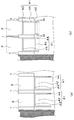
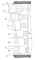
従来、このような溢水の防止を目的として、燃料貯蔵プールの内壁に平板を設けるなどしてスロッシングによる揺動を抑制する装置(例えば、特許文献1参照。)がある。このような装置について、図20を用いて以下説明する。   2. Description of the Related Art Conventionally, for the purpose of preventing such overflow, there is a device that suppresses rocking caused by sloshing by providing a flat plate on the inner wall of a fuel storage pool (see, for example, Patent Document 1). Such an apparatus will be described below with reference to FIG.

図20(a)、図20(b)はそれぞれ、原子炉使用済燃料が貯蔵される使用済燃料プール101におけるスロッシングを抑制する装置の概要を示す縦断面図であり、図20(a)は水面が揺動している状態を、図20(b)は水面が揺動していない平常時の状態を示している。   20 (a) and 20 (b) are longitudinal sectional views showing an outline of an apparatus for suppressing sloshing in the spent fuel pool 101 in which spent reactor fuel is stored. FIG. FIG. 20B shows a state where the water surface is oscillating, and FIG. 20B shows a state where the water surface is not oscillating.

使用済燃料プール101の側壁110に取り付けられたヒンジ102、ヒンジ102によって回動自在に支持された平板103、平板103の一端に取り付けられた索104を介して板103を支持するアクチュエータ105から構成されている。図20(b)に示す平常時においては、板103は側壁110に沿って折り畳まれている。スロッシングによる水面の揺動が発生した場合は、アクチュエータ105を操作して索104を巻き上げる。索104の巻き上げにより、板103は図20(a)に示すように水平方向に固定され、水の運動を妨げることで水面の揺動を抑制する。   A hinge 102 attached to the side wall 110 of the spent fuel pool 101, a flat plate 103 rotatably supported by the hinge 102, and an actuator 105 that supports the plate 103 via a cord 104 attached to one end of the flat plate 103. Has been. In the normal state shown in FIG. 20B, the plate 103 is folded along the side wall 110. When the water surface swings due to sloshing, the actuator 105 is operated to wind up the rope 104. As the rope 104 is rolled up, the plate 103 is fixed in the horizontal direction as shown in FIG. 20A, and the movement of the water is prevented, thereby suppressing the fluctuation of the water surface.

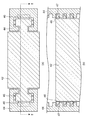
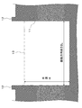
また、従来の溢水を防止する技術として、燃料貯蔵プールを取り囲むプールカーブや燃料取替え床に柵を設けて溢水を防止する装置(例えば、特許文献2参照。)がある。このような装置について、図21を用いて以下説明する。   Further, as a conventional technique for preventing overflow, there is an apparatus for preventing flooding by providing a fence on a pool curve surrounding a fuel storage pool or a fuel replacement floor (see, for example, Patent Document 2). Such an apparatus will be described below with reference to FIG.

図21は燃料貯蔵プールとしての容器201における溢水を防止する装置の概要を示す縦断面図である。容器201の上に起立壁202、横向き片203を有する移動壁204、起立壁202と移動壁204を連結する連結具205から構成された柵状の治具206が設けられている。移動壁204は連結具205が起立壁202から外れない範囲で上下方向に移動可能であり、普段は治具206を低くして作業の妨げにならないようにし、溢水を防止する際には治具206を高くすることによって溢水を防止する。
特開平8−101296号公報 特開2006−329799号公報
FIG. 21 is a longitudinal sectional view showing an outline of an apparatus for preventing overflow in the container 201 as a fuel storage pool. On the container 201, there is provided a fence-like jig 206 composed of a standing wall 202, a moving wall 204 having a lateral piece 203, and a connecting tool 205 that connects the standing wall 202 and the moving wall 204. The moving wall 204 can move in the vertical direction within a range in which the connector 205 does not come off the standing wall 202. Usually, the jig 206 is lowered so as not to hinder the work, and when the overflow is prevented, the jig Overflow is prevented by raising 206.
JP-A-8-101296 JP 2006-329799 A

上述のような溢水を防止する装置は一定の効果があると推定される。   It is estimated that the apparatus for preventing overflow as described above has a certain effect.

しかし、図20に示した燃料貯蔵プールの内壁に平板を設けた装置は、溢水を防止するためにアクチュエータの操作を必要とするため、地震発生からアクチュエータを操作し、平板が水平方向に固定されるまでに時間を要し、またアクチュエータの操作が行われなかったり、アクチュエータで故障が発生したりすると効果が得られない。   However, since the apparatus provided with a flat plate on the inner wall of the fuel storage pool shown in FIG. 20 requires the operation of the actuator to prevent overflow, the actuator is operated from the occurrence of an earthquake, and the flat plate is fixed in the horizontal direction. It takes time to complete the operation, and if the operation of the actuator is not performed or a failure occurs in the actuator, the effect cannot be obtained.

また、図21に示したプールカーブや燃料取替え床に柵状の治具を設けた装置は、治具の高さを最大限低くしても、作業性やプール内の視認性はある程度低下せざるを得ず、このような影響を小さくすることが求められている。   In addition, the apparatus provided with a fence-like jig on the pool curve or fuel replacement floor shown in FIG. 21 reduces the workability and visibility in the pool to some extent even if the jig height is reduced to the maximum. Inevitably, there is a need to reduce this effect.

また、燃料貯蔵プールは四角形であるため、四隅においては特に顕著な波高上昇が生じるが、従来の装置では四隅における波高上昇が考慮されていない。   In addition, since the fuel storage pool has a quadrangular shape, the wave height rises particularly noticeably at the four corners, but the conventional apparatus does not consider the wave height rise at the four corners.

従って、本発明は、水面の揺動発生に対して受動的に溢水を防止するように機能し、作業性、プール内の視認性への影響が小さく、プール四隅での局所的な波高上昇に対応しうる溢水防止装置の提供を目的とする。   Therefore, the present invention functions to passively prevent flooding against the occurrence of water surface fluctuation, has little effect on workability and visibility in the pool, and increases the local wave height at the four corners of the pool. The purpose is to provide an overflow prevention device that can be used.

上記目的を達成するため、本発明による溢水防止装置は、液体を収容するプールの側壁に設けられたガイドと、前記ガイドに沿って前記側壁に対して上下方向に摺動自在に設けられた堰止板と、前記堰止板に取り付けられ少なくとも一部が前記プールに収容された液体の液面上にあるように設定されるフロートと、前記側壁に取り付けられ前記板を支持する支持体と、を備えることを特徴とする。   In order to achieve the above object, an overflow prevention apparatus according to the present invention includes a guide provided on a side wall of a pool that stores liquid, and a weir provided slidably in the vertical direction with respect to the side wall along the guide. A stop plate, a float attached to the dam plate and set to be at least partially on the liquid level of the liquid contained in the pool, a support attached to the side wall and supporting the plate; It is characterized by providing.

また、本発明による溢水防止方法は、プールに収容された液体の外部への流出を防ぐ溢水防止方法であって、前記プールの側壁に配設された板を前記プールに収容された液体の液面の揺動に伴う波高上昇による前記板が受ける浮力の増大によって前記板を前記プールの縁よりも高位置へ上昇させて堰とするステップを備えることを特徴とする。   The overflow prevention method according to the present invention is an overflow prevention method for preventing the liquid stored in the pool from flowing out to the outside, wherein the plate disposed on the side wall of the pool is a liquid liquid stored in the pool. The step of raising the plate to a position higher than the edge of the pool by increasing the buoyancy received by the plate due to the rise of the wave height accompanying the swing of the surface is provided.

また、本発明によるプール改造方法は、液体を収容するプールの側壁にガイドを設ける工程と、板にフロートを取り付けて構成された溢水防止板を前記ガイドと係合させて前記ガイドに沿って上下動可能に設置する工程と、前記溢水防止板を支持する支持体を設置する工程と、を有することを特徴とする。   Further, the pool remodeling method according to the present invention includes a step of providing a guide on the side wall of a pool for storing liquid, and an overflow prevention plate configured by attaching a float to the plate to engage with the guide, and moves up and down along the guide. It has the process of installing movably, and the process of installing the support body which supports the said overflow prevention board, It is characterized by the above-mentioned.

本発明によれば、水面の揺動に対して受動的に機能する堰止板によって溢水を防止し、平常時は堰止板がプールカーブから突出していないために燃料貯蔵プールにおける作業性・視認性に与える影響が従来よりも小さく、さらに、プール四隅での局所的な波高上昇に対応可能な溢水防止装置を提供することができる。   According to the present invention, overflow is prevented by a dam plate that functions passively with respect to rocking of the water surface, and since the dam plate does not protrude from the pool curve in normal times, workability and visual recognition in the fuel storage pool It is possible to provide an overflow prevention device that has a smaller effect on the performance than conventional ones and can cope with local wave height rises at the four corners of the pool.

以下本発明の実施例について図面を参照しながら説明する。   Embodiments of the present invention will be described below with reference to the drawings.

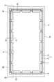
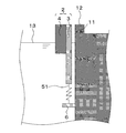
本発明の第1の実施例について、図面を用いて以下説明する。図1は本実施例による溢水防止装置を設けた燃料貯蔵プールの概要を示す上面図である。   A first embodiment of the present invention will be described below with reference to the drawings. FIG. 1 is a top view showing an outline of a fuel storage pool provided with an overflow prevention device according to this embodiment.

破線で示した60は本実施例による溢水防止装置である。燃料貯蔵プール10の側壁11に複数のレール1が一定の間隔をあけて設けられている。隣り合った2つのレール1の間には溢水防止板2が配設されており、溢水防止板2はそれぞれレール1と係合している。レール1は、溢水防止板2を上下方向に摺動させるガイドとして機能する。溢水防止板2は、堰止板3と、堰止板3の燃料貯蔵プール10内側の面に取り付けられたフロート4から構成されている。堰止板3は溢水を防止する堰として機能するものであるため、水密構造を有することが好ましく、材質は特に問わないが例えばアルミニウムやステンレス等の金属を用いて構成されている。フロート4は、例えばポリエチレンの型枠と発泡スチロールを組み合わせたフロート材を用いて構成され、堰止板3にボルトを用いるなどして取り付けられている。   60 shown by a broken line is the overflow prevention apparatus by a present Example. A plurality of rails 1 are provided on the side wall 11 of the fuel storage pool 10 at regular intervals. An overflow prevention plate 2 is disposed between two adjacent rails 1, and each overflow prevention plate 2 is engaged with the rail 1. The rail 1 functions as a guide for sliding the overflow prevention plate 2 in the vertical direction. The overflow prevention plate 2 includes a dam plate 3 and a float 4 attached to the surface of the dam plate 3 on the inner side of the fuel storage pool 10. Since the weir plate 3 functions as a weir for preventing overflow, it is preferable to have a watertight structure, and the material is not particularly limited, and is made of a metal such as aluminum or stainless steel. The float 4 is configured by using, for example, a float material in which a polyethylene mold and polystyrene foam are combined, and is attached to the dam plate 3 by using bolts.

図2を用いてレール1と溢水防止板2の係合部について詳細に説明する。図2は図1に示す破線で囲んだ領域IIを拡大して示した上面図である。   The engaging portion between the rail 1 and the overflow prevention plate 2 will be described in detail with reference to FIG. FIG. 2 is an enlarged top view showing a region II surrounded by a broken line shown in FIG.

レール1の堰止板3と対向した面にローラ5が設けられている。このローラ5はレール1と堰止板3の摩擦係数を小さくし、レール1に対して堰止板3を摺動しやすくしている。なお、ローラ5は堰止板3に設けたものとすることも可能である。   A roller 5 is provided on the surface of the rail 1 facing the blocking plate 3. This roller 5 reduces the coefficient of friction between the rail 1 and the dam plate 3 and makes it easier to slide the dam plate 3 with respect to the rail 1. The roller 5 may be provided on the blocking plate 3.

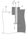
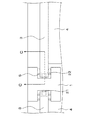
図3を用いて、溢水防止板2の構造についてさらに詳細に説明する。図3は溢水防止板2を図1に示したA−A線で切断した概要を示す縦断面図である。なお、図3は水面13が揺動していない平常時の状態を示している。   The structure of the overflow prevention plate 2 will be described in more detail with reference to FIG. FIG. 3 is a longitudinal sectional view showing an outline of the overflow prevention plate 2 cut along the line AA shown in FIG. FIG. 3 shows a normal state in which the water surface 13 is not swinging.

側壁11に支持板6が取り付けられており、支持板6は溢水防止板2を支持している。図示した水面13の水位は燃料貯蔵プール10で地震等による揺動が起こっていない平常時の水位を示しており、フロート4の一部が水面13よりも上に出ている。また、溢水防止板2の上端は燃料貯蔵プール10の縁であるプールカーブ12と実質的に同じ高さに位置している。   A support plate 6 is attached to the side wall 11, and the support plate 6 supports the overflow prevention plate 2. The water level of the water surface 13 shown in the figure indicates a normal water level in the fuel storage pool 10 in which no fluctuation is caused by an earthquake or the like, and a part of the float 4 protrudes above the water surface 13. Further, the upper end of the overflow prevention plate 2 is located at substantially the same height as the pool curve 12 that is the edge of the fuel storage pool 10.

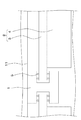
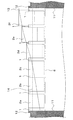
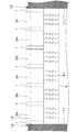
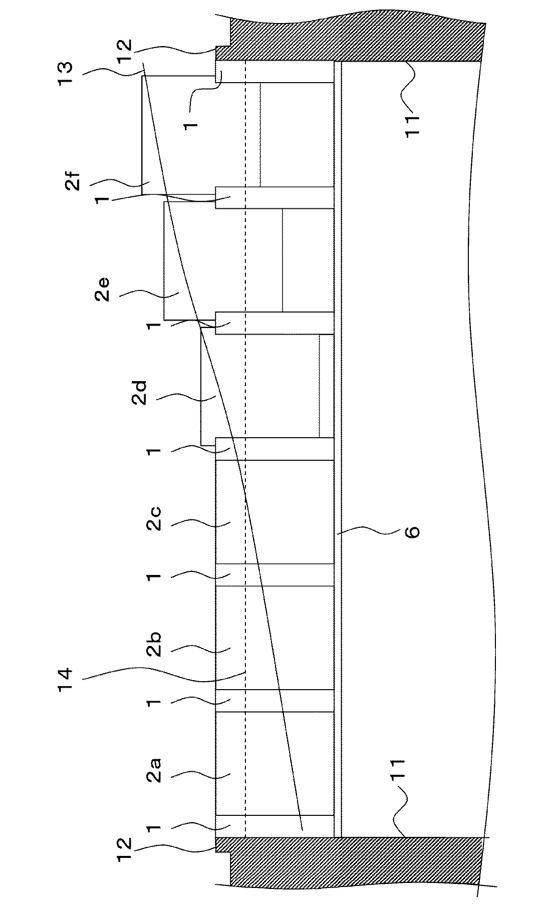
図4、図5を用いて、本実施例の作用について説明する。図4、図5はそれぞれ、燃料貯蔵プール10を図1のB−B線で示す方向から見た概要を示す矢視側面図である。図4は水面13が揺動していない平常時の状態を、図5は燃料貯蔵プール10の水面13が揺動している状態を示している。なお、図4、図5においては、図1に示す溢水防止板2g、2hを省略して図示している。   The operation of this embodiment will be described with reference to FIGS. 4 and 5 are respectively side views of the fuel storage pool 10 as viewed from the direction indicated by the line BB in FIG. 4 shows a normal state where the water surface 13 is not oscillating, and FIG. 5 shows a state where the water surface 13 of the fuel storage pool 10 is oscillating. 4 and 5, the overflow prevention plates 2g and 2h shown in FIG. 1 are omitted.

図4においては、溢水防止板2の各々がそれぞれプールカーブ12と同じ高さで停止している。この複数の溢水防止板2を、図4において左から順に溢水防止板2a,2b,2c,2d,2e,2fとする。図4に示す水面が静止した状態では溢水防止板2a,2b,2c,2d,2e,2fの各々の上端がプールカーブ12より上に突出していないため、燃料貯蔵プール10での作業や燃料貯蔵プール10内の視認を妨げない。   In FIG. 4, each of the overflow prevention plates 2 stops at the same height as the pool curve 12. The plurality of overflow prevention plates 2 are referred to as overflow prevention plates 2a, 2b, 2c, 2d, 2e, and 2f in order from the left in FIG. When the water surface shown in FIG. 4 is stationary, the upper ends of the overflow prevention plates 2a, 2b, 2c, 2d, 2e, and 2f do not protrude above the pool curve 12, so the work in the fuel storage pool 10 and the fuel storage Visibility in the pool 10 is not hindered.

図6においては、水面13が揺動しており、その水位が溢水防止板2a側で低く、溢水防止板2f側に近づくにつれて高くなっている。なお、比較のために図4に示した平常時の水位を基準水位14として破線で示す。   In FIG. 6, the water surface 13 is oscillating, and the water level is low on the overflow prevention plate 2a side and becomes higher as it approaches the overflow prevention plate 2f side. For comparison, the normal water level shown in FIG.

図5に示した状態では、溢水防止板2a,2b,2c近傍の水位が基準水位14よりも低くなっている。このため、溢水防止板2a,2b,2cの各々の水に浸かる体積は平常時に比べて小さく、浮力は平常時よりも小さくなる。したがって、溢水防止板2a,2b,2cは上昇しない。   In the state shown in FIG. 5, the water level in the vicinity of the overflow prevention plates 2 a, 2 b, 2 c is lower than the reference water level 14. Therefore, the volume of each of the overflow prevention plates 2a, 2b, and 2c immersed in water is smaller than that in the normal state, and the buoyancy is smaller than that in the normal state. Therefore, the overflow prevention plates 2a, 2b, 2c do not rise.

溢水防止板2d,2e,2f近傍の水位はそれぞれ基準水位14よりも高くなっている。水位の上昇にともなって溢水防止板2d,2e,2fが受ける浮力は大きくなり、溢水防止板2d,2e,2fは水位に応じてそれぞれ上昇する。溢水防止板2d,2e,2fの上端は平常時においてプールカーブ12と同じ高さであるため、溢水防止板2d,2e,2fが上昇すると即座にプールカーブ12よりも上に突出し、溢水を防止する堰として機能する。   The water levels in the vicinity of the overflow prevention plates 2d, 2e, 2f are higher than the reference water level 14, respectively. As the water level rises, the buoyancy received by the overflow prevention plates 2d, 2e, 2f increases, and the overflow prevention plates 2d, 2e, 2f rise according to the water level. Since the upper ends of the overflow prevention plates 2d, 2e, 2f are the same height as the pool curve 12 in normal times, when the overflow prevention plates 2d, 2e, 2f rise, they immediately protrude above the pool curve 12 to prevent overflow. Functions as a weir.

このように、燃料貯蔵プール10で水面の揺動が発生した際、局所的な水位の上昇にともなって浮力の増大により上昇して溢水を防止する溢水防止板2を設けることで、水面の揺動に対して受動的に機能し、作業性・視認性への影響を従来よりも小さくしつつ燃料貯蔵プール10からの溢水を防止することが可能である。また、水位上昇が急激であるほど溢水防止板2の上昇も速やかであるため、燃料貯蔵プール10の四隅における水位の急激な上昇に対応した溢水防止が可能である。   In this manner, when the water surface swings in the fuel storage pool 10, the overflow prevention plate 2 is provided to prevent the water from rising due to an increase in buoyancy as the local water level rises. It functions passively with respect to movement, and it is possible to prevent overflow from the fuel storage pool 10 while reducing the impact on workability and visibility compared to the conventional case. Moreover, since the rise of the overflow prevention plate 2 is quicker as the water level rises more rapidly, it is possible to prevent the overflow corresponding to the sudden rise of the water level at the four corners of the fuel storage pool 10.

また、本実施例においては、溢水防止板2の上端がプールカーブ12と実質的に同じ高さであるとして説明したが、これは平常時の作業性・視認性と、水面揺動時に溢水防止板2を速やかに堰として機能させるために望まれる事項であり、溢水防止板2の上端とプールカーブ12の高さが異なっていても構わない。また、レール1の下端に戸当を設けるなどして、溢水防止板2をレール1によって支持し、支持板6を不要とした構造とすることも可能である。   In this embodiment, the upper end of the overflow prevention plate 2 has been described as having substantially the same height as the pool curve 12. However, this is a workability / visibility during normal times and prevents overflow when the water surface swings. This is a matter desired in order for the plate 2 to quickly function as a weir, and the upper end of the overflow prevention plate 2 and the height of the pool curve 12 may be different. It is also possible to provide a structure in which the overflow prevention plate 2 is supported by the rail 1 and the support plate 6 is not required by providing a door stop at the lower end of the rail 1.

さらに、本実施例による溢水防止装置60は、燃料貯蔵プール10の側壁11にレール1と支持板6を設け、溢水防止板2をレール1と係合させてレール1に沿って上下動可能に設置するだけで完成するため、設置が容易であり、既設の燃料貯蔵プールを改造して追設することも容易である。   Furthermore, the overflow prevention device 60 according to the present embodiment is provided with the rail 1 and the support plate 6 on the side wall 11 of the fuel storage pool 10, and the overflow prevention plate 2 is engaged with the rail 1 so that it can move up and down along the rail 1. Since installation is completed simply by installation, installation is easy, and it is also easy to retrofit an existing fuel storage pool.

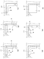
図6を用いて本実施例の変形例について説明する。図6(a)は図1に示す破線IIIの領域を拡大して示した上面図であり、図6(b)、図6(c)、図6(d)、図6(e)、図6(f)はそれぞれ本実施例の変形例による破線IIIの領域を拡大して示した上面図である。なお、各図においてはレール1に設けられるローラ5の図示を省略している。   A modification of this embodiment will be described with reference to FIG. FIG. 6A is an enlarged top view showing the area of the broken line III shown in FIG. 1, and FIG. 6B, FIG. 6C, FIG. 6D, FIG. 6 (f) is an enlarged top view showing a region indicated by a broken line III according to a modification of the present embodiment. In addition, in each figure, illustration of the roller 5 provided in the rail 1 is abbreviate | omitted.

図6(a)は本実施例の燃料貯蔵プール10の四隅に接した溢水防止板2の構造を示している。燃料貯蔵プール10の四隅においては、隣りあった溢水防止板2のフロート4の干渉を回避するため、フロート4を切り欠いて横断面を台形としているが、これは図6(b)に示すように一方のフロート4を切り欠いた構造や、図6(c)、図6(d)、図6(e)、図6(f)に示すように堰止板3をL字型にしてフロート4を取り付けた構造とすることが可能である。   FIG. 6A shows the structure of the overflow prevention plate 2 in contact with the four corners of the fuel storage pool 10 of this embodiment. At the four corners of the fuel storage pool 10, in order to avoid interference with the float 4 of the adjacent overflow prevention plate 2, the float 4 is cut out to have a trapezoidal cross section, as shown in FIG. 6 (b). The structure in which one of the floats 4 is cut out, and the weir plate 3 is formed in an L shape as shown in FIGS. 6 (c), 6 (d), 6 (e) and 6 (f). 4 can be attached.

また、図7(a)、図7(b)を用いて本実施例の別の変形例について説明する。図7(a)は本実施例の変形例による溢水防止板2の上面図、図7(b)は図7(a)に示した溢水防止板2の正面図である。   Further, another modification of the present embodiment will be described with reference to FIGS. 7 (a) and 7 (b). FIG. 7A is a top view of the overflow prevention plate 2 according to a modification of the present embodiment, and FIG. 7B is a front view of the overflow prevention plate 2 shown in FIG.

図1、図2、図3に示した本実施例による溢水防止板2は、堰止板3の燃料貯蔵プール10内側の面にフロート4を取り付けて構成されているが、図7(a)、図7(b)に示すように、堰止板3の一部を切り欠き、この切り欠き部分にフロート4を配設して、全体として板形状となる構造とすることも可能である。   The overflow prevention plate 2 according to this embodiment shown in FIGS. 1, 2 and 3 is configured by attaching the float 4 to the inner surface of the fuel storage pool 10 of the weir plate 3. As shown in FIG. 7B, a part of the blocking plate 3 may be cut out, and the float 4 may be arranged in the cutout portion to form a plate shape as a whole.

また、図8を用いて、本実施例のさらに別の変形例について説明する。図8(a)、図8(b)はそれぞれ本実施例の変形例による溢水防止板2の上面図である。   Further, another modification of the present embodiment will be described with reference to FIG. FIGS. 8A and 8B are top views of the overflow prevention plate 2 according to a modification of the present embodiment.

図1、図2、図3に示した本実施例による溢水防水板2は、レール1が溢水防止板2を上下に摺動させるガイドとして機能しているが、図8(a)に示すように、側壁11と堰止板3が対向する面について、堰止板3側に溝を設け、側壁11側に突出部を設けて係合させたガイド部7aを形成することにより、レール1の代替とすることが可能である。また、図8(b)に示すように、堰止板3側に突出部を、側壁11側に溝を設けて係合させたガイド部7bとすることも可能である。   The overflow waterproof plate 2 according to this embodiment shown in FIGS. 1, 2, and 3 functions as a guide for the rail 1 to slide the overflow prevention plate 2 up and down, as shown in FIG. In addition, on the surface where the side wall 11 and the dam plate 3 face each other, a groove is provided on the dam plate 3 side, and a protruding portion is provided on the side wall 11 side to form a guide portion 7a that is engaged, thereby forming the rail 1 Alternatives are possible. Moreover, as shown in FIG.8 (b), it is also possible to make it the guide part 7b which provided the protrusion part in the weir board 3 side and provided the groove | channel in the side wall 11 side, and was engaged.

本発明の第2の実施例について、図9(a)、図9(b)を用いて以下説明する。図9(a)図9(b)はそれぞれ本実施例による溢水防止板2の一部を示す正面図であり、図9(a)は溢水防止板2が上昇した状態を、図9(b)は溢水防止板2が図9(a)に示す位置から落下した状態を示している。なお、実施例1と同じ構成には同一の符号を付し、重複する説明は省略する。   A second embodiment of the present invention will be described below with reference to FIGS. 9 (a) and 9 (b). 9 (a) and 9 (b) are front views showing a part of the overflow prevention plate 2 according to the present embodiment, respectively, and FIG. 9 (a) shows a state in which the overflow prevention plate 2 is raised. ) Shows a state in which the overflow prevention plate 2 has dropped from the position shown in FIG. In addition, the same code | symbol is attached | subjected to the same structure as Example 1, and the overlapping description is abbreviate | omitted.

図9(a)、図9(b)ではそれぞれ支持板6と溢水防止板2の間に緩衝装置としてサスペンション8が複数設けられている。水面揺動により上昇した溢水防止板2は、近傍の水位が平常時以下に下がると、支持板6に支持されるまで下降する。   9A and 9B, a plurality of suspensions 8 are provided as buffering devices between the support plate 6 and the overflow prevention plate 2, respectively. The overflow prevention plate 2 that has risen due to the water surface swing descends until it is supported by the support plate 6 when the water level in the vicinity drops below the normal level.

本実施例によれば、実施例1と同様の効果を奏するとともに、サスペンション8を設けることによって、溢水防止板2が下降して支持板6に接触する際の負荷を緩和することが可能である。なお、このサスペンション8は溢水防止板2とは接続されていないため、溢水防止板2の上昇を妨げない。   According to the present embodiment, the same effects as in the first embodiment can be obtained, and by providing the suspension 8, it is possible to reduce the load when the overflow prevention plate 2 descends and contacts the support plate 6. . Since the suspension 8 is not connected to the overflow prevention plate 2, it does not prevent the overflow prevention plate 2 from rising.

なお、サスペンション8は溢水防止板2と指示板6の間に介在していればよく、例えば溢水防止板2の底面に設けてあっても構わない。   The suspension 8 only needs to be interposed between the overflow prevention plate 2 and the indicator plate 6, and may be provided on the bottom surface of the overflow prevention plate 2, for example.

本発明の第3の実施例について、図面を用いて以下説明する。なお、実施例1と同じ構成には同一の符号を付し、重複する説明は省略する。   A third embodiment of the present invention will be described below with reference to the drawings. In addition, the same code | symbol is attached | subjected to the same structure as Example 1, and the overlapping description is abbreviate | omitted.

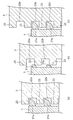
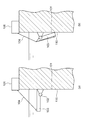
図10は、本実施例による溢水防止板2とレール1の係合部近傍を拡大した上面図である。図11(a)、図11(b)、図11(c)はそれぞれ図10に示すC−C線で切断した断面を示す縦断面図である。   FIG. 10 is an enlarged top view of the vicinity of the engaging portion between the overflow prevention plate 2 and the rail 1 according to this embodiment. 11 (a), 11 (b), and 11 (c) are longitudinal sectional views showing cross sections cut along the line CC shown in FIG.

本実施例ではレール1と堰止板3の係合部において、レール1に複数のラッチ21が、堰止板3にラッチ21の受け部22がそれぞれ設けられている。図11(a)に示すように、ラッチ21はそれぞれ受け部22に嵌入しており、ラッチ21が堰止板3を支持して溢水防止板2の下降を防いでいる。   In the present embodiment, a plurality of latches 21 are provided on the rail 1 and a receiving part 22 of the latch 21 is provided on the dam plate 3 in the engaging portion between the rail 1 and the dam plate 3. As shown in FIG. 11A, the latches 21 are fitted into the receiving portions 22, respectively, and the latches 21 support the damming plate 3 to prevent the overflow prevention plate 2 from descending.

図11(b)は堰止板3が図11(a)の状態から少し上昇した状態を示している。堰止板3が上昇する際は、ラッチ21は張り出し部23に押し込まれ、レール1に収納される。このように、堰止板3はラッチ21に阻害されずに上昇可能である。   FIG. 11B shows a state in which the blocking plate 3 is slightly raised from the state of FIG. When the weir plate 3 is raised, the latch 21 is pushed into the overhanging portion 23 and stored in the rail 1. Thus, the dam plate 3 can be raised without being obstructed by the latch 21.

図11(c)は堰止板3が図11(b)からさらに上昇した状態を示しており、ラッチ21がふたたび受け部22に嵌入しており、堰止板3を支持している。   FIG. 11C shows a state in which the dam plate 3 is further raised from FIG. 11B, and the latch 21 is fitted again into the receiving portion 22 to support the dam plate 3.

このように、レール1に設けたラッチ21と堰止板3に設けた受け部22とが、堰止板3が上昇した後に下降することを防ぐ逆止手段として機能する。これによって、溢水防止板2は水面13の揺動に応じてプールカーブ12からいったん突出した後は、ラッチ21によって支持されるため下降せず、堰として機能する。水面の揺動が収まった後は、ラッチ21による堰止板3の支持を解除して溢水防止板2を下降させる。これは、あらかじめラッチ21を手動で収納可能とするなど一時的に支持解除が可能な機構とすればよいが、他の方法として溢水防止板2をレール1の上方に完全に抜き去り、レール1の下方から溢水防止板2を挿入することも可能である。   In this manner, the latch 21 provided on the rail 1 and the receiving portion 22 provided on the dam plate 3 function as a check means for preventing the dam plate 3 from descending after being raised. As a result, the overflow prevention plate 2 once protrudes from the pool curve 12 in response to the swing of the water surface 13 and is supported by the latch 21 so that it does not descend and functions as a weir. After the oscillation of the water surface is settled, the support of the dam plate 3 by the latch 21 is released and the overflow prevention plate 2 is lowered. This may be a mechanism capable of temporarily releasing the support, such as allowing the latch 21 to be stored manually beforehand, but as another method, the overflow prevention plate 2 is completely removed above the rail 1 and the rail 1 It is also possible to insert the overflow prevention plate 2 from below.

本実施例によれば、実施例1と同様の効果を奏するとともに、溢水防止板2の下降を防止する逆止手段を設けることにより、プールカーブ12より突出した溢水防止板2が上昇した位置で保持されるため、その後にさらに高い水位上昇が起こった際、水位に対する溢水防止板2の追随性を向上することが可能である。   According to the present embodiment, the same effect as in the first embodiment can be obtained, and at the position where the overflow prevention plate 2 protruding from the pool curve 12 is raised by providing the check means for preventing the overflow prevention plate 2 from descending. Therefore, when the water level rises higher after that, the followability of the overflow prevention plate 2 with respect to the water level can be improved.

また、本実施例においては溢水防止板2がラッチ21によってレール1に支持されるため、支持板6を不要とすることも可能である。   In the present embodiment, the overflow prevention plate 2 is supported by the rail 1 by the latch 21, so that the support plate 6 can be dispensed with.

なお、本実施例においてはレール1にラッチ21を、堰止板3に受け部22を設けるものとして説明したが、堰止板3にラッチ21を、レール1に受け部22を設けた構成とすることも可能である。   In this embodiment, the latch 21 is provided on the rail 1 and the receiving portion 22 is provided on the dam plate 3. However, the latch 21 is provided on the dam plate 3 and the receiving portion 22 is provided on the rail 1. It is also possible to do.

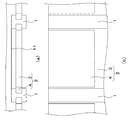
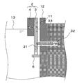
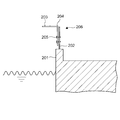
本発明の第4の実施例について、図12、図13を用いて以下説明する。なお、実施例1と同じ構成には同一の符号を付し、重複する説明は省略する。図12、図13は本実施例による溢水防止装置60を図1に示したA−A線で切断した縦断面図であり、図12は平常時の状態を、図13は溢水防止板2が上昇した位置で保持されている状態を示している。   A fourth embodiment of the present invention will be described below with reference to FIGS. In addition, the same code | symbol is attached | subjected to the same structure as Example 1, and the overlapping description is abbreviate | omitted. FIGS. 12 and 13 are longitudinal sectional views of the overflow prevention device 60 according to the present embodiment taken along line AA shown in FIG. 1. FIG. 12 shows a normal state, and FIG. It shows the state held in the raised position.

本実施例においては、燃料貯蔵プール10の側壁11に非貫通孔31が設けられており、非貫通孔31には弾性体32と支持棒33が収納されている。弾性体32はその一端が非貫通孔31奥の閉塞端に固定され、他端が支持棒33と接続している。支持棒33は弾性体32によって非貫通孔31から燃料貯蔵プール10の内側へ押されている。   In this embodiment, a non-through hole 31 is provided in the side wall 11 of the fuel storage pool 10, and an elastic body 32 and a support bar 33 are accommodated in the non-through hole 31. One end of the elastic body 32 is fixed to the closed end behind the non-through hole 31, and the other end is connected to the support rod 33. The support rod 33 is pushed by the elastic body 32 from the non-through hole 31 to the inside of the fuel storage pool 10.

図12に示す平常時においては、支持棒33は堰止板3によって押さえられている。   In the normal state shown in FIG. 12, the support bar 33 is pressed by the blocking plate 3.

図13に示すように、堰止板3の下端が非貫通孔31よりも高い位置まで上昇すると、支持棒33は弾性体32に押されて燃料貯蔵プール10の内側に向けて突出する。突出した支持棒33が溢水防止板2を支持するため、溢水防止板2は図13に示した位置よりも低位置に下降しなくなる。   As shown in FIG. 13, when the lower end of the blocking plate 3 rises to a position higher than the non-through hole 31, the support bar 33 is pushed by the elastic body 32 and protrudes toward the inside of the fuel storage pool 10. Since the protruding support bar 33 supports the overflow prevention plate 2, the overflow prevention plate 2 does not descend to a position lower than the position shown in FIG.

本実施例によれば、実施例1と同様の効果を奏するとともに、燃料貯蔵プール10の側壁11に設けた非貫通孔31、弾性体32、支持棒33を溢水防止板2の下降を防止する逆止手段として機能させることができる。   According to the present embodiment, the same effect as that of the first embodiment is obtained, and the non-through hole 31, the elastic body 32, and the support rod 33 provided in the side wall 11 of the fuel storage pool 10 are prevented from descending the overflow prevention plate 2. It can function as a check means.

また、支持棒33の先端にローラを設けるなどして、堰止板3と支持棒33の接触部の摩擦係数を小さくすることも可能である。   It is also possible to reduce the friction coefficient of the contact portion between the weir plate 3 and the support bar 33 by providing a roller at the tip of the support bar 33.

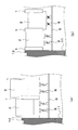
本発明の第5の実施例について、図14、図15を用いて以下説明する。なお、実施例1と同じ構成には同一の符号を付し、重複する説明は省略する。   A fifth embodiment of the present invention will be described below with reference to FIGS. In addition, the same code | symbol is attached | subjected to the same structure as Example 1, and the overlapping description is abbreviate | omitted.

図14(a)、図14(b)は本実施例による溢水防止装置60を図1に示すB−B線で切断した断面の一部を示す断面図、図15(a)は溢水防止装置60を図14(b)に示したD−D線で切断した断面図、図15(b)は溢水防止装置60を図15(a)に示したE−E線で切断した断面図である。   14 (a) and 14 (b) are cross-sectional views showing a part of the cross section of the overflow prevention device 60 according to this embodiment taken along line BB shown in FIG. 1, and FIG. 15 (a) is an overflow prevention device. 60 is a cross-sectional view taken along line DD shown in FIG. 14B, and FIG. 15B is a cross-sectional view taken from the overflow prevention device 60 taken along line EE shown in FIG. 15A. .

本実施例においては、支持板6に代えて、支持部本体42、堰止板支持部43、支持柱44から構成された支持部41が設けられている。支持部本体42は燃料貯蔵プール10の側壁11に取り付けられている。堰止板支持部43は支持部本体42の上に設置され、堰止板3を支持している。支持柱44は支持部43と一体化しており、支持部43から下方へのびている。この支持柱43は支持部本体42の側面と接触し、係合している。   In the present embodiment, instead of the support plate 6, a support portion 41 including a support portion main body 42, a dam plate support portion 43, and a support column 44 is provided. The support body 42 is attached to the side wall 11 of the fuel storage pool 10. The dam plate support 43 is installed on the support body 42 and supports the dam 3. The support pillar 44 is integrated with the support portion 43 and extends downward from the support portion 43. The support pillar 43 is in contact with and engaged with the side surface of the support body 42.

支持部本体42と支持柱44の係合部について、図15を用いて説明する。支持部本体42の側面にT字型の突出部が設けられており、この突出部が支持柱44に設けられた溝に嵌合する形で支持部本体42と支持柱44が係合している。この係合部には、支持柱44の下降を防ぐ逆止手段として、支持部本体42にラッチ46が、支持柱44にラッチ46の受け部47が設けられている。   The engaging part of the support part main body 42 and the support pillar 44 will be described with reference to FIG. A T-shaped protruding portion is provided on the side surface of the supporting portion main body 42, and the supporting portion main body 42 and the supporting column 44 are engaged with each other so that the protruding portion fits into a groove provided in the supporting column 44. Yes. The engaging portion is provided with a latch 46 on the support portion main body 42 and a receiving portion 47 of the latch 46 on the support column 44 as a non-return means for preventing the support pillar 44 from descending.

以下、本実施例の作用について説明する。   Hereinafter, the operation of the present embodiment will be described.

図14(a)は平常時の状態を示している。堰止板支持部43が支持部本体42に乗っており、支持部本体42に直接支持されている。図14(b)は堰止板3が上昇した状態を示している。堰止板支持部43は堰止板3とともに上昇する。これは、堰止板支持部43を堰止板3に取り付け、堰止板3に取り付けられたフロート4の浮力によって上昇する構成、または堰止板支持部43にフロートを取り付け、堰止板支持部43自身の浮力で上昇する構成などが考えられる。上昇した堰止板支持部43は、支持柱44を介して支持部本体42に支持されている。   FIG. 14A shows a normal state. The dam plate support 43 is on the support body 42 and is directly supported by the support body 42. FIG. 14B shows a state in which the weir plate 3 is raised. The dam plate support 43 is raised together with the dam plate 3. This is because the dam plate support 43 is attached to the dam plate 3 and is lifted by the buoyancy of the float 4 attached to the dam plate 3, or the float is attached to the dam plate support 43 to support the dam plate. The structure which raises by the buoyancy of the part 43 itself etc. can be considered. The rising weir plate support portion 43 is supported by the support portion main body 42 via the support pillar 44.

図15(a)、図15(b)を用い、支持柱44の下降を防ぐ逆止手段の構成について説明する。支持部本体42と支持柱44の係合部にはローラ45が設けられており、支持部本体42と支持柱44の摩擦係数を小さくしている。ローラ45は支持部本体42側、支持柱44側の何れに固定されていてもよい。支持部本体42にはラッチ46が複数設けられており、支持柱44には受け部47が複数設けられている。ラッチ46は受け部47に嵌入し、支持中44の下降を防止する。支持中44が上昇する際は、ラッチ46は支持中44に押されて支持部本体42に収納され、支持柱44の上昇を阻害しない。   With reference to FIGS. 15A and 15B, the structure of the check means for preventing the support pillar 44 from descending will be described. A roller 45 is provided at an engaging portion between the support portion main body 42 and the support column 44 to reduce the friction coefficient between the support portion main body 42 and the support column 44. The roller 45 may be fixed to either the support portion main body 42 side or the support column 44 side. The support body 42 is provided with a plurality of latches 46, and the support pillar 44 is provided with a plurality of receiving portions 47. The latch 46 is fitted into the receiving portion 47 to prevent the lowering 44 during the support. When the support 44 is raised, the latch 46 is pushed by the support 44 and accommodated in the support portion main body 42, and does not hinder the support column 44 from rising.

このように、堰止板3を支持する堰止板支持部43が堰止板3とともに上昇し、かつ堰止板支持部43の下降を防止する逆止手段を設けることにより、溢水防止板2の下降を防止する逆止手段として機能させることができる。   Thus, the overflow prevention plate 2 is provided by providing the check means for preventing the lowering of the dam plate support part 43 while the dam plate support part 43 supporting the dam plate 3 rises together with the dam plate 3. It can be made to function as a check means for preventing the lowering.

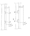
本発明の第6の実施例について、図16、図17、図18を用いて以下説明する。なお、実施例1と同じ構成には同一の符号を付し、重複する説明は省略する。   A sixth embodiment of the present invention will be described below with reference to FIGS. 16, 17, and 18. FIG. In addition, the same code | symbol is attached | subjected to the same structure as Example 1, and the overlapping description is abbreviate | omitted.

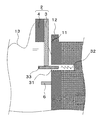
図16は本実施例による溢水防止装置60を図1に示すA−A線で切断した縦断面図、図17、図18は本実施例による溢水防止装置60を図1に示すB−B線で切断した縦断面図であり、図17は水面13が揺動していない平常時の状態を、図18は水面13が揺動している状態を示している。   FIG. 16 is a longitudinal sectional view of the overflow prevention device 60 according to the present embodiment taken along line AA shown in FIG. 1, and FIGS. 17 and 18 show the overflow prevention device 60 according to the present embodiment taken along line BB shown in FIG. FIG. 17 shows a normal state where the water surface 13 is not oscillating, and FIG. 18 shows a state where the water surface 13 is oscillating.

本実施例においては、支持板6の上にコイルバネ51が設けられており、支持板6はコイルバネ51を介して溢水防止板2を支持している。   In this embodiment, a coil spring 51 is provided on the support plate 6, and the support plate 6 supports the overflow prevention plate 2 via the coil spring 51.

本実施例の作用について、図18を用いて以下説明する。図18においては、水面13が揺動しており、溢水防止板2a近傍で最も低く、溢水防止板2fに近づくほど高くなっている。なお、比較のために平常時の水位を基準水位14として破線で示す。溢水防止板2a、2b、2cの近傍では水面13が基準水位14よりも低いため、溢水防止板2a、2b、2cが下降している。溢水防止板2d、2e、2fの近傍では水面13が基準水位14よりも高くなっているため、水位に応じて溢水防止板2d、2e、2fが上昇している。   The effect | action of a present Example is demonstrated below using FIG. In FIG. 18, the water surface 13 is oscillating, is lowest in the vicinity of the overflow prevention plate 2a, and becomes higher as it approaches the overflow prevention plate 2f. For comparison, a normal water level is indicated by a broken line as a reference water level 14. Since the water surface 13 is lower than the reference water level 14 in the vicinity of the overflow prevention plates 2a, 2b, 2c, the overflow prevention plates 2a, 2b, 2c are lowered. Since the water surface 13 is higher than the reference water level 14 in the vicinity of the overflow prevention plates 2d, 2e, and 2f, the overflow prevention plates 2d, 2e, and 2f rise according to the water level.

このような構成にすることにより、溢水防止板2が高位置から急に下降して支持板6に衝突することを防止することができる。また、溢水防止板2近傍の水位が基準水位14よりも低い位置から急激に上昇する際、溢水防止板2には溢水防止板2の下降によって圧縮されていたコイルバネ51の復元力とフロート4の浮力が働くため、溢水防止板2は速やかに上昇するために水位の急激な変化に対する追随性を向上することが可能である。具体的には、燃料貯蔵プール10の振動方向長さの半分をL、燃料貯蔵プール10の水深をH、重力加速度をgとしたときに、ハウスナーの理論によって以下の式(1)で求められるスロッシングの1次固有角振動数ωがコイルバネ51の固有振動数となるように、すなわちスロッシングの1次固有角振動数ωとコイルバネ51の固有振動数とを一致するようにコイルバネ51を設置することで、水位変化に対する溢水防止板2の追随性を向上させることができる。

Figure 2009168564
With such a configuration, it is possible to prevent the overflow prevention plate 2 from suddenly descending from the high position and colliding with the support plate 6. Further, when the water level in the vicinity of the overflow prevention plate 2 suddenly rises from a position lower than the reference water level 14, the overflow prevention plate 2 has the restoring force of the coil spring 51 compressed by the fall of the overflow prevention plate 2 and the float 4 Since the buoyancy works, the overflow prevention plate 2 rises quickly, so that it is possible to improve the followability to a sudden change in the water level. Specifically, when half of the vibration direction length of the fuel storage pool 10 is L, the water depth of the fuel storage pool 10 is H, and the gravitational acceleration is g, the following equation (1) is obtained according to Hausner's theory. The coil spring 51 is installed so that the primary natural angular frequency ω of the sloshing becomes the natural frequency of the coil spring 51, that is, the primary natural angular frequency ω of the sloshing coincides with the natural frequency of the coil spring 51. Thus, it is possible to improve the followability of the overflow prevention plate 2 against the water level change.
Figure 2009168564

なお、振動方向長さと水深を図19に図示する。図19は燃料貯蔵プール10の縦断面図であり、溢水防止装置60を省略して図示している。   The vibration direction length and water depth are shown in FIG. FIG. 19 is a vertical cross-sectional view of the fuel storage pool 10, with the overflow prevention device 60 omitted.

以上本発明の実施例について図を参照して説明してきたが、上記複数の実施例に説明した特徴を任意に組み合わせたところの構成であってもよく、例えば実施例3と実施例5を組み合わせ、レール1と堰止板3の係合部に設けたラッチ21と受け部22を、また支持部41の支持部本体42と支持柱44に設けたラッチ46と受け部47を同時に備える構成とすることも可能である。   The embodiment of the present invention has been described with reference to the drawings. However, the configuration described in the above embodiments may be arbitrarily combined. For example, the embodiment 3 and the embodiment 5 may be combined. The latch 21 and the receiving portion 22 provided at the engaging portion of the rail 1 and the blocking plate 3, and the latch 46 and the receiving portion 47 provided at the support portion main body 42 and the support pillar 44 of the support portion 41 are provided at the same time. It is also possible to do.

また、本発明は上記実施例に限定されるものでなく、発明の趣旨を逸脱しない範囲でいろいろの変形を採ることができる。当業者にあっては、具体的な実施例において本発明の技術思想および技術範囲から逸脱せずに種種の変形・変更を加えることが可能である。例えば、上述の各実施例は原子炉燃料を貯える燃料貯蔵プール10に対する溢水を防止するものとして説明してきたが、プールはこれに限定されず、より一般的な溢水対策を要するプールに対しても同様に適用可能である。   The present invention is not limited to the above-described embodiments, and various modifications can be made without departing from the spirit of the invention. Those skilled in the art can make various modifications and changes in specific embodiments without departing from the technical idea and scope of the present invention. For example, each of the above-described embodiments has been described as preventing flooding of the fuel storage pool 10 that stores the reactor fuel. However, the pool is not limited to this, and is also applicable to pools that require more general measures against flooding. The same applies.

本発明の実施例1による溢水防止装置60の概要を示す上面図。The top view which shows the outline | summary of the overflow prevention apparatus 60 by Example 1 of this invention. 実施例1による溢水防止装置60の破線II領域の拡大上面図。The enlarged top view of the broken line II area | region of the overflow prevention apparatus 60 by Example 1. FIG. 実施例1による溢水防止装置60のA−A線断面図。FIG. 3 is a cross-sectional view taken along line AA of the overflow preventing device 60 according to the first embodiment. 実施例1による溢水防止装置60のB−B線矢視図。The BB arrow directional view of the overflow prevention apparatus 60 by Example 1. FIG. 実施例1による溢水防止装置60のB−B線矢視図。The BB arrow directional view of the overflow prevention apparatus 60 by Example 1. FIG. 実施例1とその変形例による溢水防止装置60の破線III領域の拡大上面図。The enlarged top view of the broken line III area | region of the overflow prevention apparatus 60 by Example 1 and its modification. 実施例1とその変形例による溢水防止装置60の要部拡大上面図。The principal part enlarged top view of the overflow prevention apparatus 60 by Example 1 and its modification. 実施例1の変形例による溢水防止装置60の要部拡大上面図。The principal part enlarged top view of the overflow prevention apparatus 60 by the modification of Example 1. FIG. 実施例2による溢水防止装置60の要部拡大正面図。The principal part expansion front view of the overflow prevention apparatus 60 by Example 2. FIG. 実施例3による溢水防止装置60の要部拡大上面図。The principal part expansion top view of the overflow prevention apparatus 60 by Example 3. FIG. 実施例3による溢水防止装置60のC−C線断面図。CC sectional view of the overflow preventing device 60 according to the third embodiment. 実施例4による溢水防止装置60のA−A線断面図。FIG. 6 is a cross-sectional view of the overflow preventing device 60 according to the fourth embodiment, taken along line AA. 実施例4による溢水防止装置60のA−A線断面図。FIG. 6 is a cross-sectional view of the overflow preventing device 60 according to the fourth embodiment, taken along line AA. 実施例5による溢水防止装置60の要部拡大正面図。The principal part enlarged front view of the overflow prevention apparatus 60 by Example 5. FIG. (a)は実施例5による溢水防止装置60のD−D線断面図で、(b)は実施例5による溢水防止装置60のE−E線断面図。(A) is DD sectional view of the overflow prevention apparatus 60 by Example 5, (b) is EE sectional view taken on the line of the overflow prevention apparatus 60 by Example 5. FIG. 実施例6による溢水防止装置60のA−A線断面図。AA line sectional view of overflow apparatus 60 by Example 6. FIG. 実施例6による溢水防止装置60のB−B線矢視図。The BB line arrow directional view of the overflow prevention apparatus 60 by Example 6. FIG. 実施例6による溢水防止装置60のB−B線矢視図。The BB line arrow directional view of the overflow prevention apparatus 60 by Example 6. FIG. 燃料貯蔵プール10の振動方向長さを示す縦断面図。FIG. 3 is a longitudinal sectional view showing the vibration direction length of the fuel storage pool 10. 従来のスロッシング溢水防止装置60の概要を示す縦断面図。The longitudinal cross-sectional view which shows the outline | summary of the conventional sloshing overflow prevention apparatus 60. FIG. 従来の別のスロッシング溢水防止装置60の概要を示す縦断面図。The longitudinal cross-sectional view which shows the outline | summary of another conventional sloshing overflow prevention apparatus 60. FIG.

符号の説明Explanation of symbols

1 レール
2、2a、2b、2c、2d、2e、2f、2g、2h 溢水防止板
3 堰止板
4 フロート
5 ローラ
6 支持板
7a、7b ガイド部
8 サスペンション
10 燃料貯蔵プール
11 側壁
12 プールカーブ
13 水面
14 基準水位
21、21a、21b ラッチ
22、22a、22b、22c 受け部
23 張り出し部
31 非貫通孔
32 弾性体
33 支持棒
41 支持部
42 支持部本体
43 堰止板支持部
44 支持柱
45 ローラ
46 ラッチ
47 受け部
51 コイルバネ
60 溢水防止装置
101 使用済燃料プール
102 ヒンジ
103 板
104 索
105 アクチュエータ
110 側壁
201 容器
202 起立壁
203 横向き片
204 移動壁
205 連結具
206 治具
1 Rail 2, 2a, 2b, 2c, 2d, 2e, 2f, 2g, 2h Overflow prevention plate 3 Damping plate 4 Float 5 Roller 6 Support plate 7a, 7b Guide portion 8 Suspension 10 Fuel storage pool 11 Side wall 12 Pool curve 13 Water surface 14 Reference water level 21, 21a, 21b Latch 22, 22a, 22b, 22c Receiving portion 23 Overhang portion 31 Non-through hole 32 Elastic body 33 Support rod 41 Support portion 42 Support portion main body 43 Dam plate support portion 44 Support column 45 Roller 46 Latch 47 Receiving part 51 Coil spring 60 Overflow prevention device 101 Spent fuel pool 102 Hinge 103 Plate 104 Rope 105 Actuator 110 Side wall 201 Container 202 Standing wall 203 Lateral piece 204 Moving wall 205 Connecting tool 206 Jig

Claims (15)

液体を収容するプールの側壁に設けられたガイドと、
前記ガイドに沿って前記側壁に対して上下方向に摺動自在に設けられた堰止板と、
前記堰止板に取り付けられ少なくとも一部が前記プールに収容された液体の液面上にあるように設定されるフロートと、
前記側壁に取り付けられ前記板を支持する支持体と、
を備えることを特徴とする溢水防止装置。
A guide provided on the side wall of the pool containing the liquid;
A dam plate provided slidably in the vertical direction with respect to the side wall along the guide;
A float attached to the weir plate and set to be at least partially on the surface of the liquid contained in the pool;
A support attached to the side wall and supporting the plate;
An overflow prevention device characterized by comprising:
前記ガイドは前記側壁に取り付けられたレールであることを特徴とする請求項1記載の溢水防止装置。   The overflow prevention device according to claim 1, wherein the guide is a rail attached to the side wall. 前記ガイドは、前記側壁と前記堰止板の前記側壁と対向する面の何れか一方の上下にわたって設けられた溝と、他方に設けられ前記溝に嵌合する突出部から構成されることを特徴とする請求項1記載の溢水防止装置。   The guide is composed of a groove provided over one of the side wall and a surface of the dam plate facing the side wall, and a protrusion provided on the other and fitted into the groove. The overflow prevention apparatus according to claim 1. 前記堰止板と前記支持体の間に設けられ前記堰止板が下降して前記支持体に接触することによる負荷を吸収する緩衝装置を有することを特徴とする請求項1乃至請求項3の何れか1項記載の溢水防止装置。   4. The shock absorber according to claim 1, further comprising a shock absorber provided between the barrier plate and the support body for absorbing a load caused by the barrier plate descending and contacting the support body. 5. The overflow prevention apparatus of any one of Claims. 前記堰止板が上昇した場合にこの堰止板の下降を防ぐ逆止手段を備えることを特徴とする請求項1乃至請求項4の何れか1項記載の溢水防止装置。   The overflow prevention device according to any one of claims 1 to 4, further comprising a check means for preventing the barrier plate from descending when the barrier plate is raised. 前記逆止手段は、前記堰止板の側面に設けられた凹部と、前記ガイドまたは前記堰止板と対向した前記プールの側壁に設けられ前記凹部に嵌入するラッチを有し、このラッチは前記堰止板が上昇した場合に前記ガイドまたは前記プールの側壁に収納され得るよう設定されていることを特徴とする請求項5記載の溢水防止装置。   The non-return means includes a recess provided on a side surface of the dam plate, and a latch provided on a side wall of the pool facing the guide or the dam plate, and fitted into the recess. 6. The overflow prevention device according to claim 5, wherein the overflow prevention device is set so that it can be stored in a side wall of the guide or the pool when the weir plate rises. 前記逆止手段は、前記堰止板と対向する前記プールの側壁に設けられた非貫通孔と、この非貫通孔の閉塞端に設けられた弾性体と、一端を前記弾性体に支持され他端を前記堰止板に支持された第2の支持体を有し、前記堰止板の下端が前記非貫通孔の開口部よりも高位置に上昇した場合に前記第2の支持体が前記弾性体によって前記非貫通孔から突出し前記板の下端を下方から支持することを特徴とする請求項5記載の溢水防止装置。   The non-return means includes a non-through hole provided in a side wall of the pool facing the damming plate, an elastic body provided at a closed end of the non-through hole, and one end supported by the elastic body. A second support body having an end supported by the dam plate, and the second support body when the lower end of the dam plate rises higher than the opening of the non-through hole. 6. The overflow prevention device according to claim 5, wherein the elastic body protrudes from the non-through hole and supports the lower end of the plate from below. 前記支持体は前記プールの側壁に取り付けられた支持部本体、前記支持部本体に上下方向に設けられたレール状の溝、前記支持部本体の上部に配設され前記堰止板と一体に構成された支持部、前記板に設けられ前記溝と上下に摺動自在に係合した支持柱、前記支持柱の前記溝と対向する面に設けられた第2の凹部、前記溝に設けられ前記第2の凹部に嵌入し前記支持柱の下降を防止する第2のラッチから構成され、この支持体は前記第2のラッチが前記堰止板の上昇にともなって上昇した前記支持柱を支持することで前記逆止手段として機能することを特徴とする請求項5記載の溢水防止装置。   The support body includes a support body attached to the side wall of the pool, a rail-like groove provided in the support body in the vertical direction, and is disposed on the support body to be integrated with the dam plate. A support column provided on the plate and slidably engaged with the groove up and down, a second recess provided on a surface of the support column facing the groove, and provided in the groove The second latch is inserted into the second recess to prevent the support pillar from descending, and the support supports the support pillar that has been lifted by the second latch as the dam plate is lifted. 6. The overflow prevention device according to claim 5, wherein the overflow prevention device functions as the check means. 前記支持体は、前記プールの側壁に取り付けられた支持部本体、前記支持部本体に上下方向に設けられたレール状の溝、前記本体の上部に配設され前記板を支持する支持部、前記支持部に取り付けられた第2のフロート、前記堰止板に設けられ前記溝と上下に摺動自在に係合した支持柱、前記支持柱の前記溝と対向する面に設けられた第2の凹部、前記溝に設けられ前記第2の凹部に嵌入し前記支持柱の下降を防止する第2のラッチから構成され、この支持体は前記第2のラッチが前記堰止板の上昇にともなって上昇した前記支持柱を支持することで前記逆止手段として機能することを特徴とする請求項5記載の溢水防止装置。   The support body includes a support body attached to a side wall of the pool, a rail-like groove provided in the support body in the vertical direction, a support portion disposed on an upper portion of the body and supporting the plate, A second float attached to a support portion; a support column provided on the blocking plate and slidably engaged with the groove; and a second column provided on a surface of the support column facing the groove. A concave portion is provided in the groove, and is configured by a second latch that fits into the second concave portion and prevents the support pillar from descending. This support body is formed by the second latch as the dam plate rises. The overflow prevention device according to claim 5, wherein the overflow prevention device functions as the check means by supporting the raised support pillar. 前記支持体と前記堰止板の間に設けられた弾性体を備え、前記支持体は前記弾性体を介して前記板を支持することを特徴とする請求項1乃至請求項3の何れか記載の溢水防止装置。   The overflow according to any one of claims 1 to 3, further comprising an elastic body provided between the support and the damming plate, wherein the support supports the plate via the elastic body. Prevention device. 前記弾性体は前記堰止板を下方から支持するコイルバネであることを特徴とする請求項10記載の溢水防止装置。   The overflow prevention device according to claim 10, wherein the elastic body is a coil spring that supports the dam plate from below. 前記プールの振動方向長さの半分をL、前記プールに収容された液体の深さをH、重力加速度をgとしたとき、前記コイルバネの固有角振動数ωが
Figure 2009168564
となるよう設定されたことを特徴とする請求項11記載の溢水防止装置。
When the half of the vibration direction length of the pool is L, the depth of the liquid contained in the pool is H, and the gravitational acceleration is g, the natural angular frequency ω of the coil spring is
Figure 2009168564
The overflow prevention device according to claim 11, wherein the overflow prevention device is set to be.
前記プールは原子炉燃料を貯蔵する燃料貯蔵プールであることを特徴とする請求項1乃至請求項12の何れか1項記載の溢水防止装置。   The overflow prevention device according to any one of claims 1 to 12, wherein the pool is a fuel storage pool for storing nuclear reactor fuel. プールに収容された液体の外部への流出を防ぐ溢水防止方法であって、
前記プールの側壁に配設された板を前記プールに収容された液体の液面の揺動に伴う波高上昇による前記板が受ける浮力の増大によって前記板を前記プールの縁よりも高位置へ上昇させて堰とするステップを備えることを特徴とする溢水防止方法。
An overflow prevention method for preventing the liquid contained in the pool from flowing out to the outside,
The plate disposed on the side wall of the pool is raised to a position higher than the edge of the pool due to an increase in buoyancy received by the plate due to a rise in the wave height associated with the fluctuation of the liquid level of the liquid contained in the pool. A method for preventing overflow, comprising a step of making a weir.
液体を収容するプールの側壁にガイドを設ける工程と、
板にフロートを取り付けて構成された溢水防止板を前記ガイドと係合させて前記ガイドに沿って上下動可能に設置する工程と、
前記溢水防止板を支持する支持体を設置する工程と、
を有することを特徴とするプール改造方法。
Providing a guide on the side wall of the pool containing the liquid;
A step of engaging an overflow prevention plate configured by attaching a float to the plate with the guide so as to be movable up and down along the guide;
Installing a support for supporting the overflow prevention plate;
A pool remodeling method characterized by comprising:
JP2008005688A 2008-01-15 2008-01-15 Overflow prevention device, overflow prevention method and pool remodeling method Expired - Fee Related JP5058830B2 (en)

Priority Applications (1)

Application Number Priority Date Filing Date Title
JP2008005688A JP5058830B2 (en) 2008-01-15 2008-01-15 Overflow prevention device, overflow prevention method and pool remodeling method

Applications Claiming Priority (1)

Application Number Priority Date Filing Date Title
JP2008005688A JP5058830B2 (en) 2008-01-15 2008-01-15 Overflow prevention device, overflow prevention method and pool remodeling method

Publications (3)

Publication Number Publication Date
JP2009168564A true JP2009168564A (en) 2009-07-30
JP2009168564A5 JP2009168564A5 (en) 2010-06-03
JP5058830B2 JP5058830B2 (en) 2012-10-24

Family

ID=40969907

Family Applications (1)

Application Number Title Priority Date Filing Date
JP2008005688A Expired - Fee Related JP5058830B2 (en) 2008-01-15 2008-01-15 Overflow prevention device, overflow prevention method and pool remodeling method

Country Status (1)

Country Link
JP (1) JP5058830B2 (en)

Cited By (1)

* Cited by examiner, † Cited by third party
Publication number Priority date Publication date Assignee Title
JP2011185791A (en) * 2010-03-09 2011-09-22 Tokyo Electric Power Co Inc:The Overflow prevention fence of storage tank

Families Citing this family (1)

* Cited by examiner, † Cited by third party
Publication number Priority date Publication date Assignee Title
CN107218421B (en) * 2017-07-28 2019-04-12 江苏华洋新思路能源装备股份有限公司 Passive relief panel of the nuclear power unit with drain function

Citations (7)

* Cited by examiner, † Cited by third party
Publication number Priority date Publication date Assignee Title
JPS5546141A (en) * 1978-09-29 1980-03-31 Hitachi Ltd Fuel storage pool
JPS59151193U (en) * 1983-03-29 1984-10-09 株式会社東芝 Nuclear power plant pool equipment
JPS59166195U (en) * 1983-04-21 1984-11-07 三和テッキ株式会社 shock absorber
JPH02221569A (en) * 1989-02-20 1990-09-04 Kajima Corp Directively synchronizing pendulum type sloshing damper
JPH08101296A (en) * 1994-09-30 1996-04-16 Toshiba Corp Sloshing overflow preventer
JPH08209976A (en) * 1995-01-31 1996-08-13 Kajima Corp Sloshing vibration control device using moving plate having small opening
JP2006329799A (en) * 2005-05-26 2006-12-07 Toshiba Corp Sloshing overflow prevention device

Patent Citations (7)

* Cited by examiner, † Cited by third party
Publication number Priority date Publication date Assignee Title
JPS5546141A (en) * 1978-09-29 1980-03-31 Hitachi Ltd Fuel storage pool
JPS59151193U (en) * 1983-03-29 1984-10-09 株式会社東芝 Nuclear power plant pool equipment
JPS59166195U (en) * 1983-04-21 1984-11-07 三和テッキ株式会社 shock absorber
JPH02221569A (en) * 1989-02-20 1990-09-04 Kajima Corp Directively synchronizing pendulum type sloshing damper
JPH08101296A (en) * 1994-09-30 1996-04-16 Toshiba Corp Sloshing overflow preventer
JPH08209976A (en) * 1995-01-31 1996-08-13 Kajima Corp Sloshing vibration control device using moving plate having small opening
JP2006329799A (en) * 2005-05-26 2006-12-07 Toshiba Corp Sloshing overflow prevention device

Cited By (1)

* Cited by examiner, † Cited by third party
Publication number Priority date Publication date Assignee Title
JP2011185791A (en) * 2010-03-09 2011-09-22 Tokyo Electric Power Co Inc:The Overflow prevention fence of storage tank

Also Published As

Publication number Publication date
JP5058830B2 (en) 2012-10-24

Similar Documents

Publication Publication Date Title
JP5166309B2 (en) Switchgear
JP5936580B2 (en) Inundation prevention device for pit type multistory parking lot
JP5166311B2 (en) Switchgear
JP5058830B2 (en) Overflow prevention device, overflow prevention method and pool remodeling method
JP4772489B2 (en) Reactor building
JP4519714B2 (en) Sloshing overflow prevention device
JP5979556B2 (en) Floating-type temporary cut-off construction method
KR100879059B1 (en) Cut valve
WO2016174919A1 (en) Floating body type flap gate
KR20150096570A (en) Tidal buoyancy gravity power plant and method of development
KR101400119B1 (en) Pumpgate having apparatus for dropping prevention
KR20100017026A (en) Floating pier
JP6509017B2 (en) Seismic isolation structure and seismic isolation repair method for existing buildings
JP2010281128A (en) Movable breakwater and operation method of movable breakwater
KR101675221B1 (en) Safely automatic banister using buoyancy
JP2006008147A (en) Sloshing suppressing apparatus
KR20170074112A (en) Up-lifting force control device
KR20090064876A (en) Doorframe for window
KR20190002787A (en) Floating bridge structure
JP5569858B2 (en) Fence prevention fence for storage tank
WO2014024566A1 (en) Device submersion prevention structure
JP2006317230A (en) Fence structure of fuel storage pool
JP2009228247A (en) Remodeling method for floating roof type storage tank
JP2009168564A5 (en)
KR101099523B1 (en) Apparatus for guiding connection of structures

Legal Events

Date Code Title Description
A521 Written amendment

Free format text: JAPANESE INTERMEDIATE CODE: A523

Effective date: 20100419

A621 Written request for application examination

Free format text: JAPANESE INTERMEDIATE CODE: A621

Effective date: 20100419

A977 Report on retrieval

Free format text: JAPANESE INTERMEDIATE CODE: A971007

Effective date: 20101216

A131 Notification of reasons for refusal

Free format text: JAPANESE INTERMEDIATE CODE: A131

Effective date: 20110121

RD02 Notification of acceptance of power of attorney

Free format text: JAPANESE INTERMEDIATE CODE: A7422

Effective date: 20111125

RD04 Notification of resignation of power of attorney

Free format text: JAPANESE INTERMEDIATE CODE: A7424

Effective date: 20111205

A131 Notification of reasons for refusal

Free format text: JAPANESE INTERMEDIATE CODE: A131

Effective date: 20120131

A521 Written amendment

Free format text: JAPANESE INTERMEDIATE CODE: A523

Effective date: 20120402

TRDD Decision of grant or rejection written
A01 Written decision to grant a patent or to grant a registration (utility model)

Free format text: JAPANESE INTERMEDIATE CODE: A01

Effective date: 20120706

A01 Written decision to grant a patent or to grant a registration (utility model)

Free format text: JAPANESE INTERMEDIATE CODE: A01

A61 First payment of annual fees (during grant procedure)

Free format text: JAPANESE INTERMEDIATE CODE: A61

Effective date: 20120801

FPAY Renewal fee payment (event date is renewal date of database)

Free format text: PAYMENT UNTIL: 20150810

Year of fee payment: 3

FPAY Renewal fee payment (event date is renewal date of database)

Free format text: PAYMENT UNTIL: 20150810

Year of fee payment: 3

LAPS Cancellation because of no payment of annual fees