JP2009166399A - Liquid jet head alignment apparatus and alignment method thereof - Google Patents
Liquid jet head alignment apparatus and alignment method thereof Download PDFInfo
- Publication number
- JP2009166399A JP2009166399A JP2008008516A JP2008008516A JP2009166399A JP 2009166399 A JP2009166399 A JP 2009166399A JP 2008008516 A JP2008008516 A JP 2008008516A JP 2008008516 A JP2008008516 A JP 2008008516A JP 2009166399 A JP2009166399 A JP 2009166399A
- Authority
- JP
- Japan
- Prior art keywords
- optical system
- alignment
- mirror
- reference mark
- optical
- Prior art date
- Legal status (The legal status is an assumption and is not a legal conclusion. Google has not performed a legal analysis and makes no representation as to the accuracy of the status listed.)
- Withdrawn
Links
- 239000007788 liquid Substances 0.000 title claims abstract description 46
- 238000000034 method Methods 0.000 title claims abstract description 15
- 230000003287 optical effect Effects 0.000 claims abstract description 154
- 238000003384 imaging method Methods 0.000 claims description 7
- 239000000976 ink Substances 0.000 description 99
- 238000003825 pressing Methods 0.000 description 34
- 239000000853 adhesive Substances 0.000 description 8
- 230000001070 adhesive effect Effects 0.000 description 8
- 238000004891 communication Methods 0.000 description 8
- 239000000758 substrate Substances 0.000 description 8
- 239000011521 glass Substances 0.000 description 7
- 238000004519 manufacturing process Methods 0.000 description 6
- 230000001681 protective effect Effects 0.000 description 5
- 239000000463 material Substances 0.000 description 4
- 238000005304 joining Methods 0.000 description 3
- 238000010586 diagram Methods 0.000 description 2
- 238000010438 heat treatment Methods 0.000 description 2
- 230000002093 peripheral effect Effects 0.000 description 2
- 238000000018 DNA microarray Methods 0.000 description 1
- 230000002411 adverse Effects 0.000 description 1
- 230000015572 biosynthetic process Effects 0.000 description 1
- 239000007772 electrode material Substances 0.000 description 1
- 238000005516 engineering process Methods 0.000 description 1
- 239000005357 flat glass Substances 0.000 description 1
- -1 for example Substances 0.000 description 1
- 230000001678 irradiating effect Effects 0.000 description 1
- 239000004973 liquid crystal related substance Substances 0.000 description 1
- 230000000644 propagated effect Effects 0.000 description 1
- 238000004080 punching Methods 0.000 description 1
- 239000010453 quartz Substances 0.000 description 1
- VYPSYNLAJGMNEJ-UHFFFAOYSA-N silicon dioxide Inorganic materials O=[Si]=O VYPSYNLAJGMNEJ-UHFFFAOYSA-N 0.000 description 1
- 238000003860 storage Methods 0.000 description 1
- 239000000126 substance Substances 0.000 description 1
- 229920001187 thermosetting polymer Polymers 0.000 description 1
- 239000012780 transparent material Substances 0.000 description 1
Images
Classifications
-
- B—PERFORMING OPERATIONS; TRANSPORTING
- B41—PRINTING; LINING MACHINES; TYPEWRITERS; STAMPS
- B41J—TYPEWRITERS; SELECTIVE PRINTING MECHANISMS, i.e. MECHANISMS PRINTING OTHERWISE THAN FROM A FORME; CORRECTION OF TYPOGRAPHICAL ERRORS
- B41J2/00—Typewriters or selective printing mechanisms characterised by the printing or marking process for which they are designed
- B41J2/005—Typewriters or selective printing mechanisms characterised by the printing or marking process for which they are designed characterised by bringing liquid or particles selectively into contact with a printing material
- B41J2/01—Ink jet
- B41J2/135—Nozzles
- B41J2/145—Arrangement thereof
-
- B—PERFORMING OPERATIONS; TRANSPORTING
- B41—PRINTING; LINING MACHINES; TYPEWRITERS; STAMPS
- B41J—TYPEWRITERS; SELECTIVE PRINTING MECHANISMS, i.e. MECHANISMS PRINTING OTHERWISE THAN FROM A FORME; CORRECTION OF TYPOGRAPHICAL ERRORS
- B41J2202/00—Embodiments of or processes related to ink-jet or thermal heads
- B41J2202/01—Embodiments of or processes related to ink-jet heads
- B41J2202/19—Assembling head units
Landscapes
- Particle Formation And Scattering Control In Inkjet Printers (AREA)
Abstract
【課題】高精度の位置決めを行うことができる液体噴射ヘッドのアライメント装置及びそのアライメント方法を提供する。
【解決手段】インクジェット式記録ヘッド220のアライメントマーク22が位置決めされる基準マーク401を有するマスク410と、光軸L1を有する第1の光学系501と光軸L2を有する第2の光学系502とを備え、第1の光学系501は基準マーク401に焦点を合わせ得るとともに第2の光学系502はアライメントマーク22に焦点を合わせ得るように構成された二焦点顕微鏡500とを具備し、二焦点顕微鏡500には、各光軸L1、L2が一致して基準マーク401及びアライメントマーク22に入射するよう第2のミラー509の反射面の向きを調節する光軸調節手段520を設けた。
【選択図】図5A liquid ejecting head alignment apparatus and an alignment method thereof capable of performing positioning with high accuracy are provided.
A mask 410 having a reference mark 401 on which an alignment mark 22 of an ink jet recording head 220 is positioned, a first optical system 501 having an optical axis L1, and a second optical system 502 having an optical axis L2. And the first optical system 501 includes a bifocal microscope 500 configured to focus on the reference mark 401 and the second optical system 502 configured to focus on the alignment mark 22. The microscope 500 is provided with an optical axis adjusting unit 520 that adjusts the direction of the reflecting surface of the second mirror 509 so that the optical axes L1 and L2 coincide with each other and enter the reference mark 401 and the alignment mark 22.
[Selection] Figure 5
Description
本発明は液体噴射ヘッドのアライメント装置及びそのアライメント方法に関する。 The present invention relates to a liquid jet head alignment apparatus and an alignment method thereof.
インクジェット式プリンタやプロッタ等のインクジェット式記録装置は、インクカートリッジやインクタンクなどの液体収容部に収容されたインクを、ノズルプレートに設けられたノズル開口からインク滴として吐出するインクジェット式記録ヘッドを含むインクジェット式記録ヘッドユニット(以下、ヘッドユニットと言う)を具備する。ヘッドユニットに設けられたインクジェット式記録ヘッドは、所定位置に位置決め(アライメント)され、固定板等の固定部材に接合されている(例えば、特許文献1参照)。 An ink jet recording apparatus such as an ink jet printer or a plotter includes an ink jet recording head that discharges ink stored in a liquid storage portion such as an ink cartridge or an ink tank as ink droplets from a nozzle opening provided in a nozzle plate. An ink jet recording head unit (hereinafter referred to as a head unit) is provided. The ink jet recording head provided in the head unit is positioned (aligned) at a predetermined position and joined to a fixing member such as a fixing plate (see, for example, Patent Document 1).
かかる位置決めは、インクジェット式記録ヘッドの液体吐出面(例えば、ノズルプレート)に設けられたアライメントマークが、平板状のガラスマスクに設けられた基準マークに合致するようにインクジェット式記録ヘッドを移動させることにより行われる。 Such positioning is performed by moving the ink jet recording head so that the alignment mark provided on the liquid ejection surface (for example, nozzle plate) of the ink jet recording head matches the reference mark provided on the flat glass mask. Is done.
ここで、高精度の位置決めを行なうためには、基準マークとアライメントマークとの距離を可及的に近接させる必要がある。そこで、ノズルプレートをガラスマスクに密着させて所定のアライメントを行なう方法が提案されている(例えば、特許文献2参照)。 Here, in order to perform highly accurate positioning, it is necessary to make the distance between the reference mark and the alignment mark as close as possible. Therefore, a method of performing predetermined alignment by bringing the nozzle plate into close contact with the glass mask has been proposed (for example, see Patent Document 2).
ところが、このようにノズルプレートをガラスマスクに密着させた場合には両者の間に異物が挟み込まれる可能性があるばかりでなく、ガラスマスク等の表面に傷を付ける可能性がある。 However, when the nozzle plate is brought into close contact with the glass mask in this way, not only foreign substances may be sandwiched between them, but the surface of the glass mask or the like may be damaged.
かかる問題を解決するためにはガラスマスクとノズルプレートとの間に空間を設ければ良いが、今度は前記空間の存在により基準マークとアライメントマークとの距離が大きくなり、位置決め精度に悪影響を及ぼすという問題が顕在化する。すなわち、ガラスマスクの基準マークとノズルプレートのアライメントマークとを一度に一つの光学系で観察しようとすると、その分大きな被写界深度を採る必要がある。ところが、被写界深度が大きくなればなるほど、光学系の倍率を上げることができなくなり、このことが位置決め精度の高精度化を図る際の障害となる。 In order to solve such a problem, a space may be provided between the glass mask and the nozzle plate, but this time, the presence of the space increases the distance between the reference mark and the alignment mark, which adversely affects the positioning accuracy. The problem becomes obvious. That is, if the reference mark on the glass mask and the alignment mark on the nozzle plate are to be observed with one optical system at a time, it is necessary to increase the depth of field accordingly. However, as the depth of field increases, it becomes impossible to increase the magnification of the optical system, which becomes an obstacle to increase the positioning accuracy.
また、距離が離れた基準マークとアライメントマークとを観察する場合、先ず基準マークに焦点を合わせてこの基準マークを観察した後、レンズをその光軸方向に移動させ、今度はアライメントマークに焦点を合わせてこの基準マークを観察する方法も考えられるが、この場合にはレンズの移動精度がそのままアライメント精度に影響を与えるため、ある程度以上の高精度化は望めない。 When observing a reference mark and an alignment mark that are separated from each other, first focus on the reference mark and observe the reference mark, then move the lens in the direction of the optical axis, and this time focus on the alignment mark. In addition, a method of observing the reference mark is also conceivable, but in this case, since the lens moving accuracy directly affects the alignment accuracy, it is not possible to expect a higher degree of accuracy.
なお、このような問題は、インクジェット式記録ヘッドユニットの製造に伴うアライメントの際だけでなく、他の液体噴射ヘッドユニットの製造に伴うアライメントの際にも同様に発生する。 Such a problem occurs not only at the time of alignment accompanying the manufacture of the ink jet recording head unit but also at the time of alignment accompanying the manufacture of another liquid jet head unit.
本発明は、上述の如き従来技術に鑑み、基準マークとアライメントマークとの距離が離れている場合でも高精度の位置決めを行うことができる液体噴射ヘッドのアライメント装置及びそのアラインメント方法を提供することを目的とする。 The present invention provides a liquid ejecting head alignment apparatus and an alignment method thereof that can perform high-precision positioning even when the distance between the reference mark and the alignment mark is long in view of the conventional technology as described above. Objective.
上記課題を解決する本発明の第1の態様は、ノズルプレートに設けられたノズル開口から液体を噴射する複数の液体噴射ヘッドの位置決めを行う液体噴射ヘッドのアライメント装置であって、前記液体噴射ヘッドの液体吐出面に設けられたアライメントマークが位置決めされる基準マークを有する透明部材であるマスクと、前記マスクの前記液体噴射ヘッド側とは反対側から前記基準マーク及び前記アライメントマークの方向に向けられた光軸をそれぞれ有する2つの光学系を備え、第1の光学系は前記基準マークに焦点を合わせ得るとともに第2の光学系は前記アライメントマークに焦点を合わせ得るように構成された二焦点顕微鏡とを具備し、前記第1の光学系と前記第2の光学系とは、前記第1の光学系及び前記第2の光学系の各光軸のうち少なくとも何れか一方の光軸がミラーを経由し、各光軸が外部の撮像手段に至るように構成され、前記二焦点顕微鏡には、前記ミラーの反射面の向きを調節する光軸調節手段が設けられたことを特徴とする液体噴射ヘッドのアライメント装置にある。
かかる態様では、光軸調節手段により、基準マーク及びアライメントマークに入射する二焦点顕微鏡の各光学系の各光軸の方向を一致させることができる。これにより、位置決めされた液体噴射ヘッドとマスクとを平面視したとき基準マークとアライメントマークとが完全に一致するように、液体噴射ヘッドの位置決めを高精度に行うことができる。
A first aspect of the present invention that solves the above problem is an alignment apparatus for a liquid ejecting head that positions a plurality of liquid ejecting heads that eject liquid from nozzle openings provided in a nozzle plate, the liquid ejecting head being configured as described above. A mask, which is a transparent member having a reference mark on which an alignment mark provided on the liquid discharge surface is positioned, and is directed from the opposite side of the mask to the liquid jet head side in the direction of the reference mark and the alignment mark. A bifocal microscope configured so that the first optical system can focus on the reference mark and the second optical system can focus on the alignment mark. The first optical system and the second optical system are optical axes of the first optical system and the second optical system. At least one of the optical axes passes through a mirror, and each optical axis reaches an external imaging unit. The bifocal microscope has an optical axis adjusting unit that adjusts the direction of the reflecting surface of the mirror. Is provided in an alignment apparatus for a liquid jet head.
In this aspect, the optical axis adjusting means can make the directions of the optical axes of the optical systems of the bifocal microscope incident on the reference mark and the alignment mark coincide. Accordingly, the liquid ejecting head can be positioned with high accuracy so that the reference mark and the alignment mark completely coincide with each other when the positioned liquid ejecting head and the mask are viewed in plan.
また、前記第1の光学系と前記第2の光学系とは、前記各光軸の双方が前記第1の光学系及び前記第2の光学系にそれぞれ設けられたミラーを経由するように構成され、一方のミラーは、該ミラーを経由する前記光軸が前記基準マーク及び前記アライメントマークに垂直に入射するように固定され、他方のミラーは、その反射面の向きが前記光軸調節手段により調節されるように構成されたことが好ましい。これによれば、一方のミラーは、一方の光軸が基準マークに垂直に入射するよう固定されているので、他方のミラーのみを調節するだけで、容易に各光軸を一致させると共に、各光軸を基準マーク及びアライメントマークに垂直に入射させることができる。 Further, the first optical system and the second optical system are configured such that both of the optical axes pass through mirrors respectively provided in the first optical system and the second optical system. One mirror is fixed so that the optical axis passing through the mirror is perpendicularly incident on the reference mark and the alignment mark, and the other mirror has its reflecting surface oriented by the optical axis adjusting means. It is preferably configured to be adjusted. According to this, since one of the mirrors is fixed so that one of the optical axes is perpendicularly incident on the reference mark, it is possible to easily match each optical axis by adjusting only the other mirror, The optical axis can be perpendicularly incident on the reference mark and the alignment mark.
さらに、本発明の他の態様は、2つの被写体にそれぞれ焦点位置を調節し得る第1の光学系と第2の光学系とを備え、前記第1の光学系及び前記第2の光学系の各光軸のうち少なくとも何れか一方の光軸がミラーを経由し、各光軸が外部の撮像手段に至るように構成された二焦点顕微鏡を用いて、ノズル開口から液体を噴射する複数の液体噴射ヘッドの位置決めを行う液体噴射ヘッドのアライメント方法であって、前記アライメントマークが位置決めされる基準マークが設けられている透明部材であるマスクの当該基準マークに対して前記第1の光学系及び前記第2の光学系の各光軸が一致して入射するように前記ミラーの反射面の向きを調節し、前記マスクと前記液体噴射ヘッドとを相対向させ、前記第1の光学系は前記基準マークに焦点を合わせる一方、前記第2の光学系は前記アライメントマークに焦点を合わせて前記基準マークと前記アライメントマークの画像を得ると共に、両画像が重なる位置に前記液体噴射ヘッドを移動させて位置決めを行なうことを特徴とする液体噴射ヘッドのアライメント方法にある。
かかる態様では、光軸調節手段により、基準マーク及びアライメントマークに入射する二焦点顕微鏡の各光学系の各光軸の方向を一致させることができる。これにより、位置決めされた液体噴射ヘッドとマスクとを平面視したとき基準マークとアライメントマークとが完全に一致するように、液体噴射ヘッドの位置決めを高精度に行うことができる。
Furthermore, another aspect of the present invention includes a first optical system and a second optical system that can adjust the focal positions of two subjects, respectively, and the first optical system and the second optical system. A plurality of liquids that eject liquid from nozzle openings using a bifocal microscope configured such that at least one of the optical axes passes through a mirror and each optical axis reaches an external imaging unit. A liquid ejecting head alignment method for positioning an ejecting head, wherein the first optical system and the reference mark with respect to the reference mark of a mask which is a transparent member provided with a reference mark for positioning the alignment mark The direction of the reflecting surface of the mirror is adjusted so that the respective optical axes of the second optical system are incident to coincide with each other, the mask and the liquid ejecting head are made to face each other, and the first optical system is used as the reference Focus on the mark On the other hand, the second optical system focuses on the alignment mark to obtain an image of the reference mark and the alignment mark, and moves the liquid ejecting head to a position where both images overlap to perform positioning. The liquid jet head alignment method is characterized.
In this aspect, the optical axis adjusting means can make the directions of the optical axes of the optical systems of the bifocal microscope incident on the reference mark and the alignment mark coincide. Accordingly, the liquid ejecting head can be positioned with high accuracy so that the reference mark and the alignment mark completely coincide with each other when the positioned liquid ejecting head and the mask are viewed in plan.
本発明の実施の形態に係るアライメント装置を説明するのに先立ち当該アライメントの対象となる液体噴射ヘッドの一種であるインクジェット式記録ヘッドを有するインクジェット式記録ヘッドユニットの一例を説明しておく。 Prior to describing the alignment apparatus according to the embodiment of the present invention, an example of an ink jet recording head unit having an ink jet recording head which is a kind of liquid jet head to be aligned will be described.
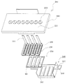
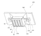
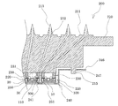
図1はインクジェット式記録ヘッドユニットの分解斜視図、図2はインクジェット式記録ヘッドユニットの組立斜視図、図3はその要部断面図である。 FIG. 1 is an exploded perspective view of the ink jet recording head unit, FIG. 2 is an assembled perspective view of the ink jet recording head unit, and FIG.
これらの図に示すように、インクジェット式記録ヘッドユニット200(以下、ヘッドユニット200と言う)は、カートリッジケース210、インクジェット式記録ヘッド220、カバーヘッド240及び固定板250を有する。
As shown in these drawings, the ink jet recording head unit 200 (hereinafter referred to as the head unit 200) includes a
これらのうち、カートリッジケース210は、インクカートリッジ(図示なし)がそれぞれ装着されるカートリッジ装着部211を有するインクカートリッジの保持部材である。インクカートリッジは、例えばブラック及び3色のカラーインクが充填された別体で構成されたインク供給手段である。すなわち、カートリッジケース210には、各色のインクカートリッジがそれぞれ装着される。
Among these, the
また、図3に特に明示するように、カートリッジケース210には、一端が各カートリッジ装着部211に開口するとともに他端がヘッドケース230側に開口する複数のインク連通路212が設けられている。さらに、カートリッジ装着部211のインク連通路212の開口部分には、インクカートリッジのインク供給口に挿入されるインク供給針213が固定されている。この固定は、インク内の気泡や異物を除去するためにインク連通路212に形成されたフィルタ(図示なし)を介して行なわれる。
Further, as clearly shown in FIG. 3, the
インクジェット式記録ヘッド220は、インクを噴射するノズル開口21が設けられたノズルプレート20と、ノズル開口21に連通する圧力発生室が形成された流路形成基板10と、圧力発生室にインクを噴射するための圧力を付与する圧電素子300と、流路形成基板10の圧電素子300が設けられた側に設けられた保護基板30とを備えている。また、流路形成基板10と保護基板30とには、圧力発生室に連通するインク室となるリザーバ100が形成されている。
The ink
一つのノズルプレート20には、ノズル開口21が並設されたノズル列21Aが2列設けられると共に、位置決めを行う際に使用されるアライメントマーク22(後に詳説する)が設けられている。本例では、アライメントマーク22は、ノズル開口21の並設方向の端部に2個設けられている。このアライメントマーク22は、ノズル開口21をポンチで穿設する工程において、当該ポンチで加工することで容易に形成できるものである。
One
各インクジェット式記録ヘッド220は、アライメントマーク22を利用して後述のアライメント装置により各インクジェット式記録ヘッド220が所定の位置に整列された状態で固定板250に固定されている。固定板250には、ノズル開口21を露出する開口部251が設けられている。
Each
また、各インクジェット式記録ヘッド220は、それぞれヘッドケース230を介してカートリッジケース210の底面にそれぞれ固定されている。ヘッドケース230には貫通孔であるインク供給連通路231が設けられており、該インク供給連通路231を介してインク連通路212からインクジェット式記録ヘッド220のリザーバ100にインクが供給されるようになっている。
Each ink
さらに、ヘッドユニット200には、図1及び図2に示すように、固定板250に対してインクジェット式記録ヘッド220とは反対側に、各インクジェット式記録ヘッド220を覆うように箱形状を有するカバーヘッド240が設けられている。このカバーヘッド240は、固定板250の開口部251に対応して開口部241が設けられている。
Further, as shown in FIGS. 1 and 2, the
カバーヘッド240には、カバーヘッド240をカートリッジケース210に位置決め固定するための固定孔247が設けられたフランジ部246が設けられている。一方、カートリッジケース210には、インク滴吐出面側に突出して、カバーヘッド240の固定孔247に挿入される突起部215が設けられており、この突起部215をカバーヘッド240の固定孔247に挿入するとともに突起部215の先端部を加熱してかしめることで、カートリッジケース210にカバーヘッド240が固定されている。
The
上述の如き構成のヘッドユニット200は、インクカートリッジからのインクをインク連通路212及びインク供給連通路231を介して、各インクジェット式記録ヘッド220のリザーバ100からノズル開口21に至るまで内部をインクで充満させる。かかる状態で、各インクジェット式記録ヘッド220は、駆動IC110からの記録信号に従い、圧力発生室に対応するそれぞれの圧電素子300に電圧を印加し、圧電素子300をたわみ変形させることにより、各圧力発生室内の圧力を上げてノズル開口21からインク滴を吐出させる。
The
本実施形態に係るアライメント装置を図面に基づき詳細に説明する。
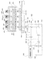
図4は本実施形態に係るアライメント装置を示す断面図である。なお、図1乃至図3と同一部分には同一番号を付している。同図に示すように、本形態に係るアライメント装置は、アライメントの対象であるインクジェット式記録ヘッド220を載置するアライメント治具400、アライメント治具400と一体となってインクジェット式記録ヘッド220を固定板250側に押圧する押圧手段450、アライメント治具400の下方からアライメント治具400を介してインクジェット式記録ヘッド220を観察するための2つの光学系を有する二焦点顕微鏡500及びマスク410を固定し二焦点顕微鏡500の光軸L1、L2と直角な水平方向に適宜移動できる移動ステージ550を有する。
The alignment apparatus according to this embodiment will be described in detail with reference to the drawings.
FIG. 4 is a cross-sectional view showing the alignment apparatus according to this embodiment. The same parts as those in FIGS. 1 to 3 are denoted by the same reference numerals. As shown in the figure, the alignment apparatus according to this embodiment fixes the
これらのうち、アライメント治具400は、少なくとも、基準マーク401が設けられた透明部材であるマスク410を具備している。透明部材とはその反対側のアライメントマークが認識できる程度の透明性を有している部材のことである。具体的には、ガラス、プラスチックなどがあるが、本発明の目的を達成できるものであればこれらの具体的な部材に限定されないことは言うまでも無い。
Among these, the
詳言すると、マスク410は、透過性を有する材料、例えば石英等のガラスからなり、本形態ではインクジェット式記録ヘッド220に接しない状態でマスク410の本体部からインクジェット式記録ヘッド220に向けて突出するとともに先端部に基準マーク401が形成された凸部411を有している。凸部411は、各基準マーク401に対してそれぞれ設けられた円柱形状の部分である。本形態では、各インクジェット式記録ヘッド220の液体吐出面、例えば、ノズルプレート20にアライメントマーク22を2つ設けたため、基準マーク401を各インクジェット式記録ヘッド220に対して2つ、合計8つ設けている。ここではノズルプレート20にアライメントマーク22を設けたが、インクジェット式記録ヘッド220の液体吐出面であれば、ノズルプレート20に限定されない。
More specifically, the
上述の如きアライメント治具400には、インクジェット式記録ヘッド220を固定板250側に押圧する押圧手段450が配設されている。すなわち、押圧手段450は、インクジェット式記録ヘッド220上に配置されるコ字状のアーム部451と、アーム部451に設けられて各インクジェット式記録ヘッド220を固定板250側に押圧する押圧部453とを具備する。
The
押圧部453は、アーム部451の各インクジェット式記録ヘッド220に相対向する領域にそれぞれ設けられている。本形態では、1つの固定板250にインクジェット式記録ヘッド220が4つ固定されるため、押圧部453は各インクジェット式記録ヘッド220に対応させてこれと同数の4個設けられている。
The
各押圧部453は、アーム部451に挿通されて軸方向に移動自在に設けられた円柱形状を有する押圧ピン454と、押圧ピン454の基端部側に設けられて押圧ピン454をインクジェット式記録ヘッド220側に付勢する付勢手段455と、押圧ピン454とインクジェット式記録ヘッド220との間に配置される押圧コマ459とで構成されている。
Each
押圧ピン454は、先端が半球状に形成され、押圧コマ459上に点接触してこの押圧コマ459を押圧するようになっている。
The
付勢手段455は、アーム部451に設けられて押圧ピン454をインクジェット式記録ヘッド220側に付勢するものであり、本形態では押圧ピン454の基端部側を囲むように設けられたねじ保持部456と、ねじ保持部456に螺合するねじ部457と、ねじ部457の先端面と押圧ピン454の基端部との間に設けられた付勢ばね458とを具備する。かくして、付勢手段455は、ねじ部457のねじ保持部456に対する締め付け量により、付勢ばね458が押圧ピン454を押圧する圧力を調整することができる。これにより押圧ピン454が押圧コマ459を押圧する圧力をそれぞれ調整可能となっている。
The urging means 455 is provided on the
押圧コマ459は、押圧ピン454とインクジェット式記録ヘッド220との保護基板30との間に配置され、押圧ピン454が押圧コマ459の上面に点接触し、その押圧ピン454の押圧力をインクジェット式記録ヘッド220の保護基板30上のほぼ全面に均等に伝播させた状態でインクジェット式記録ヘッド220を押圧することができる。なお、この押圧コマ459は、インクジェット式記録ヘッド220の保護基板30の外周形状と同一の大きさか、又は若干小さな外周形状をなしている。
The
上述の如く押圧手段450と一体となったアライメント治具400は、移動ステージ550上に配設されており、二焦点顕微鏡500の光軸L1、L2と直角な水平方向に適宜移動させるように構成してある。この結果、光軸L1、L2を固定した状態で、移動ステージ550を移動させることにより各インクジェット式記録ヘッド220に対応する各アライメントマーク22を各基準マーク401とともに光軸L1、L2上に臨ませることができる。なお、移動ステージ550において光軸L1、L2がマスク410に向かって通過する領域には、貫通孔551が設けてあり、基準マーク401を経てアライメントマーク22に至る光路を確保してある。
As described above, the
二焦点顕微鏡500は、マスク410のインクジェット式記録ヘッド220とは反対側から基準マーク401及びアライメントマーク22の方向に向けられた光軸L1、L2(図中に一点鎖線で示す)をそれぞれ有する第1の光学系501と第2の光学系502とを備えている。第1の光学系501は基準マーク401に焦点を合わせることができ、第2の光学系502はアライメントマーク22に焦点を合わせることができるように構成されている。
The
詳言すると、対物レンズ503は基準マーク401及びアライメントマーク22の方向に光軸L1、L2を向けるように鏡筒504に収納してあり、この鏡筒504が筐体505に固定されている。筐体505内には第1のビームスプリッタ506、第2のビームスプリッタ507、第1のミラー508、第2のミラー509及び第1の焦点レンズ510、第2の焦点レンズ511が収納してある。
Specifically, the
第1の光学系501は、第1のビームスプリッタ506、第1のミラー508、第1の焦点レンズ510及び第2のビームスプリッタ507から構成され、第1の光学系501の光軸L1は、第1のビームスプリッタ506を透過し、第1のミラー508で反射され、第1の焦点レンズ510を通った後、第2のビームスプリッタ507を透過して外部の撮像手段であるCCD520に至る。本実施形態では、第1のミラー508は、光軸L1がアライメントマーク22に垂直に入射するように筐体505に固定されている。
The first
第2の光学系502は、第1のビームスプリッタ506、第2の焦点レンズ511、第2のミラー509及び第2のビームスプリッタ507から構成され、第2の光学系502の光軸L2は、第1のビームスプリッタ506で反射された光が焦点レンズ511を通った後、第2のミラー509及び第2のビームスプリッタ507で反射されて外部のCCD520に至る。
The second
第2のミラー509は、その反射面の向きを自在にし得るように筐体505に取り付けられている。また、二焦点顕微鏡500には、第2のミラー509の反射面の向きを調節する光軸調節手段512が設けられている。具体的には、光軸調節手段512は、第2のミラー509の筐体505との取り付け角度を調節することで第2のミラー509の反射面の向きを調節するように構成されている。なお、このような光軸調節手段512としては、マイクロメータヘッドを好適に用いることができるが、これに限定されない。
The
このように、光軸調節手段512を介して第2のミラー509の角度を変えることで、その反射面の向きを変えることができ、その結果、光軸L2が基準マーク401に対して入射する角度を変えることが可能となっている。
Thus, by changing the angle of the
撮像手段であるCCD520は、第1の光学系501、第2の光学系502を介して基準マーク401とアライメントマーク22との画像を同時に取り込んで再生処理する。ここで、基準マーク401は焦点レンズ510の焦点位置を調整することにより、またアライメントマーク22は焦点レンズ511の焦点位置を調整することによりCCD520上にそれぞれ合焦画像を結像させる。かくして、基準マーク401及びアライメントマーク22に個別に焦点が合った鮮明な画像をCCD520上に得ることができる。
The
上記構成のアライメント装置を用いて、移動ステージ550に固定されたマスク410の基準マーク401及びノズルプレート20のアライメントマーク22の相対的な位置関係を二焦点顕微鏡500で確認しつつ、基準マーク401及びアライメントマーク22の位置決めを行なうことができる。
Using the alignment apparatus configured as described above, while confirming the relative positional relationship between the
ここで、上述したように、第2のミラー509は、その反射面の角度が調節可能となっているので、光軸調節手段512を操作することで、光軸L2の方向を調節して光軸L1の方向に一致させることができる。このとき、光軸L1は、第1のミラー508により基準マーク401に対して垂直に入射するようになっているので、光軸L1と光軸L2とは、共に基準マーク401及びアライメントマーク22に垂直に入射することになる。
Here, as described above, since the angle of the reflecting surface of the
このように、光軸L1と光軸L2とが一致すると共に、垂直に基準マーク401及びアライメントマーク22に入射するように調整された二焦点顕微鏡500を用いてインクジェット式記録ヘッド220の位置決めを行うと、光軸L2上に位置するよう移動されたアライメントマーク22は、同時に光軸L1上にも位置することになる。すなわち、各インクジェット式記録ヘッド220のアライメントマーク22と、マスク410の基準マーク401とが完全に一致した状態で位置決めされる。ここで、「完全に一致した状態」とは、位置決めされたインクジェット式記録ヘッド220とマスク410とを平面視したとき、基準マーク401とアライメントマーク22とが一致していることをいう。
As described above, the ink
ここで、光軸L1と光軸L2とが一致しておらず、光軸L2が光軸L1に対して傾いていると仮定する。この状態で、CCD520により得た画像上で、基準マーク401の画像とアライメントマーク22の画像とが一致するようにインクジェット式記録ヘッド220の位置決めをしても、実際のアライメントマーク22の位置は、光軸L2の傾きの分だけ本来在るべき位置からずれてしまう。すなわち、位置決めされたインクジェット式記録ヘッド220とマスク410とを平面視したとき、各アライメントマーク22は各基準マーク401から全体的に平行移動したようにずれた状態となる。この状態で、インクジェット式記録ヘッド220と固定板250とを接合すると、ノズル列21Aが固定板250の開口部251の片側に偏るなど、インクジェット式記録ヘッド220が固定板250に対して適切な位置に固定されない問題が生じ得る。
Here, it is assumed that the optical axis L1 and the optical axis L2 do not coincide with each other, and the optical axis L2 is inclined with respect to the optical axis L1. In this state, even if the ink
しかしながら、本発明に係るアライメント装置によれば、光軸のずれに起因する位置ずれが生じないので上記問題も生じ得ず、この結果、インクジェット式記録ヘッド220が高精度に位置決めされたヘッドユニット200を構成することができる。
However, according to the alignment apparatus of the present invention, the above-mentioned problem cannot be caused because the positional deviation due to the optical axis deviation does not occur, and as a result, the
次に、上述の如きアライメント装置を用いるインクジェット式記録ヘッド220の所定位置へのアライメント方法を説明する。本実施形態のアライメント方法は、インクジェット式記録ヘッド220のアライメントを行うに先立ち、二焦点顕微鏡500の第1の光学系501の光軸L1と第2の光学系502の光軸L2との軸合わせを行う。
Next, an alignment method of the ink
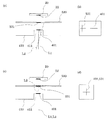
図5(a)及び図5(c)は、相対向して配設されたマスクと鏡との要部断面図であり、図5(b)及び図5(d)は、CCDを介して表示された基準マークの画像と鏡像の画像との概念図である。 FIGS. 5 (a) and 5 (c) are cross-sectional views of the main part of the mask and mirror disposed opposite to each other, and FIGS. 5 (b) and 5 (d) are illustrated through the CCD. It is a conceptual diagram of the image of the displayed reference mark and the image of a mirror image.
図5(a)に示すように、マスク410と鏡530とが平行となるように、移動ステージ550上の任意の場所に配置された図示しない鏡治具上に鏡530を載置する。これにより鏡530の鏡面には、マスク410の基準マーク401の鏡像531が映し出される。鏡530は、基準マーク401から鏡像531までの距離が、基準マーク401からノズルプレート20のアライメントマーク22までの距離の半分の位置になるように上記鏡治具上に載置されている。そして、第1の光学系501の第1の焦点レンズ510を調節して光軸L1の焦点位置を基準マーク401に合わせ、第2の光学系502の第2の焦点レンズ511を調節して光軸L2の焦点位置を鏡像531に合わせる。
As shown in FIG. 5A, the
このとき、マスク410と鏡530とは平行になっているので、基準マーク401と鏡像531とは、鏡530の鏡面の法線方向から見ると一致するようになっている。しかしながら、光軸L2が光軸L1と一致せず、鏡530に対して傾いて入射していると、図5(b)に示すように、CCD520を介して表示される基準マーク401の画像と鏡像531の画像とはずれることになる。
At this time, since the
次に、図5(b)に示した基準マーク401の画像と、鏡像531の画像とが一致するように、光軸調節手段512を介して第2のミラー509の角度を調節する。この調節の結果、図5(d)に示すように基準マーク401の画像と、鏡像531の画像とが一致すると、図5(c)に示すように、光軸L1と光軸L2とが一致すると共に、基準マーク401に対して垂直に入射するようになる。
Next, the angle of the
次に、インクジェット式記録ヘッド220の位置決めを行う。
Next, the ink
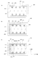
図6はインクジェット式記録ヘッドのアライメント時におけるアライメント治具の底面側から見た様子を示す底面図である。
1) 図6(a)に示すように、鏡530を取り除く。すなわち、二焦点顕微鏡500の第1の光学系501の光軸L1上に、基準マーク401のみが位置する状態となる。この結果、CCD520には基準マーク401に焦点が合った鮮明な画像が取り込まれる。
2) 図6(b)に示すように、アライメント治具400に固定板250を保持させる。3) 図6(c)に示すように、二焦点顕微鏡500の第2の光学系502の光軸L2の焦点位置を、ノズルプレート20に合わせる。この結果、CCD520にはアライメントマーク22に焦点が合った鮮明な画像が取り込まれる。そして、この画像に基づいて、アライメントマーク22の画像が基準マーク401の画像と一致するようにインクジェット式記録ヘッド220を移動させる。
FIG. 6 is a bottom view showing a state seen from the bottom side of the alignment jig during alignment of the ink jet recording head.
1) As shown in FIG. 6A, the
2) As shown in FIG. 6B, the fixing
なお、インクジェット式記録ヘッド220の位置決めは、CCD520の画像を作業者が視認しつつマイクロメータ等(図示せず)を用いて微小な位置調整を行うことで実施しても良く、またCCD520の出力画像を画像処理することにより前記マイクロメータ等を駆動モータ等により駆動させて自動的に行うようにしても良い。
4) 前記3)の工程と同様の工程を繰り返すことで、複数のインクジェット式記録ヘッド220を順次位置決めする。すなわち、光軸L1、L2は固定したままで、水平面内で移動ステージ550を図6(c)中のY軸方向に移動することで同一インクジェット式記録ヘッド220の他のアライメントマーク22と基準マーク401の位置決めを行なうとともに、X軸方向に移動することで隣接する他のインクジェット式記録ヘッド220のアライメントマーク22と基準マーク401の位置決めを行なう。
5) 押圧手段450により、複数のインクジェット式記録ヘッド220を固定板250に所定の圧力で加圧しながら接着剤を硬化させることで両者を接合する。
The ink
4) A plurality of inkjet recording heads 220 are sequentially positioned by repeating the same process as the process 3). That is, by moving the moving
5) The adhesive is cured while pressing the plurality of ink jet recording heads 220 against the fixed
このように、複数のインクジェット式記録ヘッド220を位置決めして固定板250に接合することで、高精度に所定位置に位置決めされたインクジェット式記録ヘッド220を有するヘッドユニット200を構成することができる。
In this way, by positioning the plurality of ink jet recording heads 220 and joining them to the fixed
上述した実施形態においては、第2の光学系502の第2のミラー509の角度を調整したが、本発明はこれに限定されない。例えば、第1のミラー508も、その反射面の向きを自在に変更し得るように筐体505に取り付け、光軸調節手段512によって反射面の向きを調節できるように構成してもよい。
In the embodiment described above, the angle of the
また、第1の光学系501及び第2の光学系502にそれぞれ第1のミラー508及び第2のミラー509が含まれているが、必ずしもそれぞれにミラーが含まれている必要はなく、少なくとも、光軸の方向を調整する光学系にミラーが含まれていればよい。さらに、撮像手段として1つのCCD520を用いたがこれに限定されず、各光軸L1、L2のそれぞれに1つのCCD520を用い、各CCD520がそれぞれ基準マーク401、アライメントマーク22を撮像するようにしてもよい。
In addition, the first
さらに、鏡530を用いて、基準マーク401と基準マーク401の鏡像531とを目標とし、第1の光学系501の光軸L1と、第2の光学系502の光軸L2とが一致するよう第2のミラー509を調節したが、このような鏡530を用いた調節のみに限定されない。要するに、マスク410の基準マーク401が設けられた面の法線上に鏡像531に相当する目標物を設け、該目標物に光軸L2を合わせるように光軸調節手段512を操作すればよい。
Further, the
また、上記実施形態では、アライメント治具400に押圧手段450を設けるようにしたが、特にこれに限定されず、例えば固定板250とインクジェット式記録ヘッド220とを接合する接着剤として紫外線硬化型の接着剤を用いた場合には、固定板250の接合面に接着剤を塗布した後、固定板250とインクジェット式記録ヘッド220とを当接させた状態で紫外線を照射して接着剤を硬化させることで両者を接合することができるため、押圧手段450を設けないようにしてもよい。なお、紫外線硬化型接着剤は、熱硬化性接着剤のように固定板250とインクジェット式記録ヘッド220とを所定の圧力で加圧しながら硬化させる必要がなく、加圧することによって生ずるインクジェット式記録ヘッド220と固定板250との位置ズレを防止して両者を高精度に接合することができる。
Further, in the above embodiment, the pressing means 450 is provided on the
上記実施形態では、撓み振動型のインクジェット式記録ヘッド220を例示したが、これに限定されず、例えば圧電材料と電極形成材料とを交互に積層させて軸方向に伸縮させる縦振動型のインクジェット式記録ヘッドや発熱素子等の発熱で発生するバブルによってインク滴を吐出させるインクジェット式記録ヘッド等、種々の構造のインクジェット式記録ヘッドを有するヘッドユニットに応用することができることは言うまでもない。
In the above embodiment, the flexural vibration type ink
なお、上記実施形態では、アライメントの対象となる液体噴射ヘッドとしてインクを吐出するインクジェット式記録ヘッドを有するヘッドユニットを一例として説明したが、これに限るものではなく、広く液体噴射ヘッドを有する液体噴射ヘッドユニットの製造の際に一般的に適用し得る。液体噴射ヘッドとしては、例えば、プリンタ等の画像記録装置に用いられる記録ヘッド、液晶ディスプレー等のカラーフィルタの製造に用いられる色材噴射ヘッド、有機ELディスプレー、FED(電界放出ディスプレー)等の電極形成に用いられる電極材料噴射ヘッド、バイオchip製造に用いられる生体有機物噴射ヘッド等を挙げることができる。 In the above embodiment, a head unit having an ink jet recording head that discharges ink as a liquid ejecting head to be aligned has been described as an example. However, the present invention is not limited to this, and the liquid ejecting head widely having a liquid ejecting head is used. It is generally applicable when manufacturing the head unit. Examples of the liquid ejecting head include a recording head used for an image recording apparatus such as a printer, a color material ejecting head used for manufacturing a color filter such as a liquid crystal display, an organic EL display, and an electrode formation such as an FED (field emission display). Electrode material ejecting heads used in manufacturing, bioorganic matter ejecting heads used in biochip production, and the like.
20 ノズルプレート、 21 ノズル開口、 22 アライメントマーク、 220 インクジェット式記録ヘッド、 400 アライメント治具、 401 基準マーク、 410 マスク、 500 二焦点顕微鏡、 501 第1の光学系、 502 第2の光学系、 512 光軸調節手段 20 Nozzle Plate, 21 Nozzle Opening, 22 Alignment Mark, 220 Inkjet Recording Head, 400 Alignment Jig, 401 Reference Mark, 410 Mask, 500 Bifocal Microscope, 501 First Optical System, 502 Second Optical System, 512 Optical axis adjustment means
Claims (3)
前記液体噴射ヘッドの液体吐出面に設けられたアライメントマークが位置決めされる基準マークを有する透明部材であるマスクと、
前記マスクの前記液体噴射ヘッド側とは反対側から前記基準マーク及び前記アライメントマークの方向に向けられた光軸をそれぞれ有する2つの光学系を備え、第1の光学系は前記基準マークに焦点を合わせ得るとともに第2の光学系は前記アライメントマークに焦点を合わせ得るように構成された二焦点顕微鏡とを具備し、
前記第1の光学系と前記第2の光学系とは、前記第1の光学系及び前記第2の光学系の各光軸のうち少なくとも何れか一方の光軸がミラーを経由し、各光軸が外部の撮像手段に至るように構成され、
前記二焦点顕微鏡には、前記ミラーの反射面の向きを調節する光軸調節手段が設けられた
ことを特徴とする液体噴射ヘッドのアライメント装置。 A liquid ejecting head alignment device that positions a plurality of liquid ejecting heads that eject liquid from nozzle openings provided in a nozzle plate,
A mask that is a transparent member having a reference mark on which an alignment mark provided on the liquid ejection surface of the liquid ejecting head is positioned;
The optical system includes two optical systems each having an optical axis directed in the direction of the reference mark and the alignment mark from a side opposite to the liquid jet head side of the mask, and the first optical system focuses on the reference mark. And a second optical system comprising a bifocal microscope configured to focus on the alignment mark;
The first optical system and the second optical system are configured such that at least one of the optical axes of the first optical system and the second optical system passes through a mirror, The axis is configured to reach external imaging means,
An alignment apparatus for a liquid jet head, wherein the bifocal microscope is provided with an optical axis adjusting means for adjusting a direction of a reflecting surface of the mirror.
前記第1の光学系と前記第2の光学系とは、前記各光軸の双方が前記第1の光学系及び前記第2の光学系にそれぞれ設けられたミラーを経由するように構成され、
一方のミラーは、該ミラーを経由する前記光軸が前記基準マーク及び前記アライメントマークに垂直に入射するように固定され、他方のミラーは、その反射面の向きが前記光軸調節手段により調節されるように構成された
ことを特徴とする液体噴射ヘッドのアライメント装置。 The liquid jet head alignment apparatus according to claim 1,
The first optical system and the second optical system are configured such that both of the optical axes pass through mirrors provided in the first optical system and the second optical system, respectively.
One mirror is fixed so that the optical axis passing through the mirror is perpendicularly incident on the reference mark and the alignment mark, and the direction of the reflecting surface of the other mirror is adjusted by the optical axis adjusting means. An alignment apparatus for a liquid jet head, characterized in that the apparatus is configured as described above.
前記アライメントマークが位置決めされる基準マークが設けられている透明部材であるマスクの当該基準マークに対して前記第1の光学系及び前記第2の光学系の各光軸が一致して入射するように前記ミラーの反射面の向きを調節し、
前記マスクと前記液体噴射ヘッドとを相対向させ、
前記第1の光学系は前記基準マークに焦点を合わせる一方、前記第2の光学系は前記アライメントマークに焦点を合わせて前記基準マークと前記アライメントマークの画像を得ると共に、両画像が重なる位置に前記液体噴射ヘッドを移動させて位置決めを行なうことを特徴とする液体噴射ヘッドのアライメント方法。 A first optical system capable of adjusting a focal position of each of the two subjects, and a second optical system, and at least one of the optical axes of the first optical system and the second optical system; A liquid ejecting head that positions a plurality of liquid ejecting heads that eject liquid from nozzle openings using a bifocal microscope configured such that an optical axis passes through a mirror and each optical axis reaches an external imaging unit. An alignment method,
The optical axes of the first optical system and the second optical system are incident on the reference mark of the mask, which is a transparent member provided with a reference mark on which the alignment mark is positioned. Adjust the direction of the reflective surface of the mirror,
The mask and the liquid jet head are opposed to each other;
The first optical system focuses on the reference mark, while the second optical system focuses on the alignment mark to obtain an image of the reference mark and the alignment mark, and the two images overlap each other. An alignment method of a liquid ejecting head, wherein the liquid ejecting head is moved for positioning.
Priority Applications (2)
| Application Number | Priority Date | Filing Date | Title |
|---|---|---|---|
| JP2008008516A JP2009166399A (en) | 2008-01-17 | 2008-01-17 | Liquid jet head alignment apparatus and alignment method thereof |
| US12/355,635 US20090185184A1 (en) | 2008-01-17 | 2009-01-16 | Alignment apparatus for manufacturing a liquid jet head, an alignment method for manufacturing the same and method of manufacturing a liquid jet head unit |
Applications Claiming Priority (1)
| Application Number | Priority Date | Filing Date | Title |
|---|---|---|---|
| JP2008008516A JP2009166399A (en) | 2008-01-17 | 2008-01-17 | Liquid jet head alignment apparatus and alignment method thereof |
Publications (1)
| Publication Number | Publication Date |
|---|---|
| JP2009166399A true JP2009166399A (en) | 2009-07-30 |
Family
ID=40876235
Family Applications (1)
| Application Number | Title | Priority Date | Filing Date |
|---|---|---|---|
| JP2008008516A Withdrawn JP2009166399A (en) | 2008-01-17 | 2008-01-17 | Liquid jet head alignment apparatus and alignment method thereof |
Country Status (2)
| Country | Link |
|---|---|
| US (1) | US20090185184A1 (en) |
| JP (1) | JP2009166399A (en) |
Families Citing this family (2)
| Publication number | Priority date | Publication date | Assignee | Title |
|---|---|---|---|---|
| CN104567665B (en) * | 2013-10-29 | 2017-12-22 | 中芯国际集成电路制造(上海)有限公司 | The detection method of nozzle in control wafer and coating developing machine |
| JP7374584B2 (en) * | 2016-05-20 | 2023-11-07 | ボード オブ リージェンツ,ザ ユニバーシティ オブ テキサス システム | Precise alignment of substrate coordinate system to inkjet coordinate system |
Family Cites Families (4)
| Publication number | Priority date | Publication date | Assignee | Title |
|---|---|---|---|---|
| JP4274214B2 (en) * | 2006-09-08 | 2009-06-03 | セイコーエプソン株式会社 | Liquid jet head alignment apparatus and alignment method thereof |
| JP4288519B2 (en) * | 2006-09-13 | 2009-07-01 | セイコーエプソン株式会社 | Alignment apparatus and alignment method |
| JP4207074B2 (en) * | 2006-09-14 | 2009-01-14 | セイコーエプソン株式会社 | Alignment apparatus and alignment method |
| JP4196220B2 (en) * | 2006-10-18 | 2008-12-17 | セイコーエプソン株式会社 | Liquid jet head alignment apparatus and alignment method thereof |
-
2008
- 2008-01-17 JP JP2008008516A patent/JP2009166399A/en not_active Withdrawn
-
2009
- 2009-01-16 US US12/355,635 patent/US20090185184A1/en not_active Abandoned
Also Published As
| Publication number | Publication date |
|---|---|
| US20090185184A1 (en) | 2009-07-23 |
Similar Documents
| Publication | Publication Date | Title |
|---|---|---|
| CN100557479C (en) | Calibration device and calibration method | |
| CN101164785B (en) | Apparatus and method for aligning liquid-jet head | |
| CN101138911B (en) | Alignment device and alignment method for liquid spray head | |
| JP6390961B2 (en) | Write head unit assembly apparatus and write head unit assembly method | |
| JP5691466B2 (en) | Liquid ejecting head unit and manufacturing method thereof | |
| JP2007535431A (en) | Mounting assembly | |
| US8800147B2 (en) | Alignment method of liquid-jet head unit | |
| US7643144B2 (en) | Alignment apparatus and alignment method | |
| US8069564B2 (en) | Alignment jig and alignment apparatus for liquid-jet head and method for producing liquid-jet head | |
| JP4715304B2 (en) | Alignment jig and method of manufacturing liquid jet head unit | |
| JP2013001016A (en) | Manufacturing method of liquid ejecting apparatus | |
| US20090185184A1 (en) | Alignment apparatus for manufacturing a liquid jet head, an alignment method for manufacturing the same and method of manufacturing a liquid jet head unit | |
| JP5614082B2 (en) | Liquid ejecting head unit positioning mechanism, liquid ejecting head unit, liquid ejecting apparatus, and method of manufacturing liquid ejecting head unit | |
| JP4655760B2 (en) | Alignment jig, manufacturing method thereof, and manufacturing method of liquid jet head unit | |
| JP2013039762A (en) | Liquid injection head unit, liquid injection device, and method for manufacturing liquid injection unit | |
| JP2012111098A (en) | Liquid injection head unit and method of manufacturing the same | |
| JP5263466B2 (en) | Alignment mask for liquid jet head unit, alignment apparatus for liquid jet head unit, and alignment method for liquid jet head unit | |
| JP5821547B2 (en) | Liquid ejecting head module manufacturing method, liquid ejecting head module, and liquid ejecting apparatus | |
| JP2008068515A (en) | Liquid jet head alignment jig, liquid jet head alignment apparatus, and liquid jet head alignment jig mounting method | |
| JP2009172880A (en) | Alignment method and liquid jet head manufacturing method | |
| JP2009172879A (en) | Alignment method and liquid jet head manufacturing method | |
| JP6037228B2 (en) | Droplet discharge head manufacturing method, droplet discharge head manufacturing apparatus, and droplet discharge head |
Legal Events
| Date | Code | Title | Description |
|---|---|---|---|
| A521 | Written amendment |
Free format text: JAPANESE INTERMEDIATE CODE: A821 Effective date: 20101118 |
|
| RD03 | Notification of appointment of power of attorney |
Free format text: JAPANESE INTERMEDIATE CODE: A7423 Effective date: 20101118 |
|
| RD04 | Notification of resignation of power of attorney |
Free format text: JAPANESE INTERMEDIATE CODE: A7424 Effective date: 20101118 |
|
| A621 | Written request for application examination |
Free format text: JAPANESE INTERMEDIATE CODE: A621 Effective date: 20101130 |
|
| A761 | Written withdrawal of application |
Free format text: JAPANESE INTERMEDIATE CODE: A761 Effective date: 20111212 |