JP2009163065A - Liquid toner fixing device, liquid-developing electronic printing machine and liquid toner fixing method - Google Patents
Liquid toner fixing device, liquid-developing electronic printing machine and liquid toner fixing method Download PDFInfo
- Publication number
- JP2009163065A JP2009163065A JP2008001639A JP2008001639A JP2009163065A JP 2009163065 A JP2009163065 A JP 2009163065A JP 2008001639 A JP2008001639 A JP 2008001639A JP 2008001639 A JP2008001639 A JP 2008001639A JP 2009163065 A JP2009163065 A JP 2009163065A
- Authority
- JP
- Japan
- Prior art keywords
- toner
- substrate
- liquid toner
- liquid
- transferred
- Prior art date
- Legal status (The legal status is an assumption and is not a legal conclusion. Google has not performed a legal analysis and makes no representation as to the accuracy of the status listed.)
- Withdrawn
Links
Images


Abstract
Description
本発明は、液体のキャリアに分散したトナーを用いて印刷を行う液体現像電子印刷機及びこれに用いる液体トナー定着装置並びにトナー定着方法に関する。 The present invention relates to a liquid developing electronic printer that performs printing using toner dispersed in a liquid carrier, a liquid toner fixing device, and a toner fixing method used therefor.
従来より、帯電した熱可塑性樹脂及び色素(顔料等)によって構成されトナーが液体現像剤(キャリア)内に分散された液体トナーを用いて感光体に形成された静電潜像を現像し、液体トナーを被印刷物の表面に転写し、転写された液体トナー中のトナーを被印刷物に定着させることにより印刷を行う印刷機(以下、液体現像電子印刷機という)が実用化されている。 Conventionally, an electrostatic latent image formed on a photoreceptor is developed using a liquid toner composed of a charged thermoplastic resin and a dye (pigment, etc.) and dispersed in a liquid developer (carrier). 2. Description of the Related Art Printing machines (hereinafter referred to as liquid developing electronic printers) that perform printing by transferring toner onto the surface of a printing material and fixing the toner in the transferred liquid toner to the printing material have been put into practical use.
液体現像電子印刷機は、液体トナーを用いない乾式の電子写真装置と比較して、粒子径が大幅に小さいトナーであってもトナーの飛散などの不具合が生じることなく良好に用いることができるという利点がある。粒子径が小さいトナーを用いて印刷を行うことにより、色調品質が向上することができるのに加え、被印刷物(例えば印刷用紙)の質感を反映させることができる等、印刷品質が大幅に向上するという利点がある。 The liquid developing electro-printing machine can be used satisfactorily without causing problems such as toner scattering even if the toner has a significantly smaller particle size than a dry electrophotographic apparatus that does not use liquid toner. There are advantages. Printing with toner with a small particle diameter can improve the quality of the color tone and, in addition, the quality of the printed material (for example, printing paper) can be reflected and the printing quality is greatly improved. There is an advantage.
このような液体現像電子印刷機は、一般に、一対の定着ローラにより被印刷物に転写された液体トナーを加熱及び加圧することで、被印刷物上の液体トナー中のキャリアを蒸発させるとともにトナーを溶融させて被印刷物の表面に定着(固定)させるトナー定着部を有している(例えば、特許文献1参照)。
特許文献1の技術のように一対の定着ローラにより液体トナーを加熱及び加圧するように構成すれば、被印刷物上において加熱により液体トナー中のトナーを溶融させた上で溶融したトナーを被印刷物に押し付けることができるので、トナーを定着させると同時に被印刷物表面のトナーの定着面が均されて良好な印刷面を得ることができる。
If the liquid toner is heated and pressurized by a pair of fixing rollers as in the technique of Patent Document 1, the toner in the liquid toner is melted by heating on the printed material, and the molten toner is applied to the printed material. Since the toner can be pressed, the fixing surface of the toner on the surface of the printing material is leveled, and a good printing surface can be obtained.
ところで、液体現像電子印刷機において良好にトナー画像を形成するためには、当然ながら、液体トナー中のトナーがキャリアに溶解しない性質であることが必要である。
ところが、液体現像電子印刷機においてトナーを被印刷物に定着させる際には、トナーがキャリアに溶解しない性質であることが、トナー定着部においてトナーの被印刷物に対する定着性を低下させる一因となっていることを本発明者らは見出した。
Incidentally, in order to form a toner image satisfactorily in a liquid developing electronic printing machine, it is naturally necessary that the toner in the liquid toner does not dissolve in the carrier.
However, when the toner is fixed to the printing material in the liquid developing electronic printing machine, the property that the toner does not dissolve in the carrier is a cause of lowering the fixing property of the toner to the printing material in the toner fixing portion. The present inventors have found that.
即ち、トナー定着部において加熱により溶融したトナーとキャリアとの相溶性が非常に悪いため、被印刷物上のキャリアと溶融したトナーとが分離してしまい、トナーが被印刷物に浸透及び定着することが阻害されるのである。
また、トナー定着部では図8に示すように一対の定着ローラ101,102により形成されるニップ部Nにおいて被印刷物100を加熱及び加圧するため、ニップ部Nにおいて被印刷物が略密閉状態となり、加熱によるキャリアの蒸発が十分に促進されないことも被印刷物に対するトナーの定着性の低下の要因となっている。
That is, since the compatibility between the toner melted by heating and the carrier in the toner fixing unit is very poor, the carrier on the printed material and the melted toner are separated, and the toner may permeate and fix on the printed material. It is inhibited.
Further, as shown in FIG. 8, the toner fixing unit heats and presses the printed
このように、トナーの定着性が低下すると、印刷された絵柄を形成するトナーが被印刷物から剥離し易くなる等、印刷品質が低下してしまう。
本発明はこのような課題に鑑み創案されたもので、被印刷物に対するトナーの定着性を向上させ、より高品質の印刷物を得ることができるようにした、液体トナー定着装置及び液体現像電子印刷機並びに液体トナー定着方法を提供することを目的とする。
As described above, when the toner fixing property is lowered, the printing quality is lowered, for example, the toner forming the printed pattern is easily peeled off from the printing material.
The present invention was devised in view of the above problems, and a liquid toner fixing device and a liquid developing electronic printer capable of improving a toner fixing property to a printing material and obtaining a higher quality printed material. An object of the present invention is to provide a liquid toner fixing method.
上述の目的を達成するために、本発明の液体トナー定着装置(請求項1)は、帯電した粒子状のトナーが液体のキャリア中に分散されている液体トナーを感光体上に転写することで現像したトナー画像を被印刷物に転写し、上記被印刷物に転写された上記液体トナーの内の上記トナーを上記被印刷物に定着させる液体トナー定着装置であって、上記被印刷物に転写された上記液体トナーの内の上記トナーを上記被印刷物に定着させるトナー定着手段と、上記トナー定着手段よりも上記被印刷物の搬送方向上流側に配設され、上記被印刷物に転写された上記液体トナーの内の上記キャリアを蒸発させて除去するキャリア除去手段とを有していることを特徴としている。 In order to achieve the above-mentioned object, the liquid toner fixing device according to the present invention (claim 1) transfers the liquid toner in which charged particulate toner is dispersed in a liquid carrier onto the photosensitive member. A liquid toner fixing device that transfers a developed toner image to a printing material and fixes the toner in the liquid toner transferred to the printing material to the printing material, wherein the liquid transferred to the printing material Toner fixing means for fixing the toner of the toner to the substrate, and upstream of the toner fixing means in the transport direction of the substrate, the liquid toner transferred to the substrate It has a carrier removing means for evaporating and removing the carrier.
また、上記トナー定着手段は、上記液体トナーが転写された上記被印刷物を加熱及び加圧することにより上記液体トナーの内の上記トナーを上記被印刷物に定着させるように構成されていることが好ましい(請求項2)。
これにより、トナーを加熱及び加圧することでトナーを溶融させた上で溶融したトナーを被印刷物に押し付けることができるのでトナーの凹凸が均され、被印刷物に対して効果的にトナーを定着させることができるとともに良好な印刷面を得ることができる。
Preferably, the toner fixing unit is configured to fix the toner in the liquid toner to the printing material by heating and pressurizing the printing material to which the liquid toner has been transferred ( Claim 2).
As a result, the toner is melted by heating and pressurizing the toner, and the melted toner can be pressed against the printing material, so that the unevenness of the toner is leveled and the toner is effectively fixed to the printing material. And a good printing surface can be obtained.
また、上記キャリア除去手段は、上記液体トナーが転写された上記被印刷物を昇温させる被印刷物昇温装置を有していることが好ましい(請求項3)。
被印刷物を昇温させることにより液体キャリアの蒸発を促進させて効果的に除去することができる。また、トナー定着手段に搬入される前に被印刷物を予加熱することができ、トナー定着手段における加熱量を低減することができる。
In addition, it is preferable that the carrier removing unit includes a substrate temperature increasing device for increasing the temperature of the material to which the liquid toner is transferred.
By elevating the temperature of the substrate, the evaporation of the liquid carrier can be promoted and effectively removed. Further, the printed material can be preheated before being carried into the toner fixing unit, and the heating amount in the toner fixing unit can be reduced.
また、上記被印刷物昇温装置は、上記液体トナーが転写された上記被印刷物に閃光を照射して上記被印刷物を昇温させる閃光照射装置を有していることが好ましい(請求項4)。
被印刷物を昇温させることにより液体キャリアを蒸発させて効果的に除去することができる。また、閃光により被印刷物を瞬時に昇温させることができる上、閃光により昇温させることで熱源の過照射による被印刷物の過度の昇温を防止することができる。
In addition, it is preferable that the printing material temperature increasing device includes a flash light irradiation device that heats the printing material by irradiating the printing material to which the liquid toner has been transferred with flash light.
By raising the temperature of the substrate, the liquid carrier can be evaporated and effectively removed. In addition, the temperature of the printed material can be instantaneously raised by the flash, and the temperature of the printed material can be prevented from being excessively increased by over-irradiation of the heat source.
また、上記被印刷物昇温装置は、上記閃光照射装置よりも、上記シート搬送方向上流側に配設され、上記液体トナーが転写された上記被印刷物を予め昇温させる被印刷物予加熱手段を有していることが好ましい(請求項5)。
一般に、閃光照射装置は消費する被印刷物の昇温にかかるエネルギ効率が比較的良好でなく、ランニングコストの増大の要因となるが、閃光照射装置によって被印刷物を昇温させる前に、よりエネルギ効率のよい被印刷物予加熱手段によって被印刷物を予加熱しておくことで、閃光照射装置の出力電力を低減することができ、装置全体としてのランニングコストを低下させることができる。
Further, the substrate temperature increasing device is provided on the upstream side in the sheet conveying direction with respect to the flash irradiation device, and includes a substrate preheating means for preheating the substrate to which the liquid toner has been transferred. (Claim 5).
In general, the flash irradiation device is relatively poor in energy efficiency for increasing the temperature of the printed material to be consumed, and causes an increase in running cost. However, before the temperature of the printed material is increased by the flash irradiation device, it is more energy efficient. By preheating the printed material with the good printed material preheating means, the output power of the flash irradiation device can be reduced, and the running cost of the entire device can be reduced.
また、上記キャリア除去手段は、上記トナー定着手段と上記被印刷物昇温装置との間に配設され上記被印刷物上のキャリアの蒸発を促進させるための送風機を有していることが好ましい(請求項6)。
昇温された被印刷物に空気流を作用させることにより被印刷物中の水蒸気及びキャリアの蒸発をさらに促進させることができる。
Further, the carrier removing means preferably has a blower disposed between the toner fixing means and the substrate temperature increasing device for promoting evaporation of the carrier on the substrate (claim). Item 6).
Evaporation of water vapor and carriers in the printing material can be further promoted by causing an air flow to act on the heated printing material.
なお、送風機により生じさせる空気流の流向は特に限定するものではないが、被印刷物の印刷面付近の空気圧が周囲に対して負圧となるように送風機を配設することが好ましい。例えば、被印刷物付近の空気を吸引する方向に送風機を配設してもよく、あるいは、被印刷物に対して側方から層状の空気流を送風するようにしてもよい。
被印刷物の印刷面付近の空気圧が周囲に対して負圧とすることにより、被印刷物からのキャリアの蒸発をより促進することができる。
The flow direction of the air flow generated by the blower is not particularly limited, but it is preferable to dispose the blower so that the air pressure in the vicinity of the printing surface of the printing material is negative with respect to the surroundings. For example, a blower may be disposed in a direction in which air in the vicinity of the printing material is sucked, or a layered air flow may be blown from the side with respect to the printing material.
By setting the air pressure in the vicinity of the printing surface of the substrate to be negative with respect to the surroundings, it is possible to further promote the evaporation of the carrier from the substrate.
また、上記被印刷物を載置する載置部に開口を有する開口付搬送ベルトを有し、上記被印刷物は上記開口付搬送ベルト上に載置された状態で上記キャリア除去手段を搬送されるように構成されていることが好ましい(請求項7)。
この開口付搬送ベルトは、複数の開口部を有する載置ベルトが被印刷物の幅方向に間欠的に連続するように構成された、いわゆるサクションベルトであることが好ましい。
In addition, the mounting portion on which the printed material is placed has an opening-type conveying belt having an opening, and the printed material is conveyed on the carrier removing means while being placed on the conveying belt with the opening. It is preferable to be configured as (Claim 7).
The opening-conveying belt is preferably a so-called suction belt configured such that a mounting belt having a plurality of openings is intermittently continued in the width direction of the printing material.
これによれば、単なる無端ベルト上を搬送される場合と比較して、被印刷物と空気との接触面積が増大するので、被印刷物中の水蒸気及び液体キャリアの蒸発をさらに促進させることができる。
また、上記被印刷物の端部を把持した状態で搬送するチェーングリッパを有し、上記被印刷物は上記チェーングリッパに把持された状態で上記キャリア除去手段を搬送されるように構成されていることが好ましい(請求項8)。
According to this, since the contact area between the printing medium and air is increased as compared with a case where the sheet is conveyed on a simple endless belt, it is possible to further promote evaporation of water vapor and liquid carrier in the printing medium.
In addition, a chain gripper that transports the substrate while gripping an end portion of the substrate, and the substrate is configured to be transported by the carrier removing unit while being gripped by the chain gripper. Preferred (claim 8).
これにより、被印刷物と空気との接触面積がさらに増大するので、被印刷物中の水蒸気及び液体キャリアの蒸発をさらに効果的に促進させることができる。さらに、トナー定着面の反対側の面(裏面)が被印刷物の搬送手段であるチェーングリッパと非接触であるので、両面印刷時においても裏面画像が温度上昇により軟化しても擦れ等の画像みだれを生じる恐れがない。 As a result, the contact area between the printing medium and air further increases, so that evaporation of water vapor and liquid carrier in the printing medium can be further effectively promoted. Further, since the opposite surface (back surface) of the toner fixing surface is not in contact with the chain gripper which is the conveying means for the printing material, even when the back surface image is softened due to the temperature rise, image fringing such as rubbing is caused. There is no fear of producing.
また、上記キャリア除去手段は、上記被印刷物昇温装置に対して上記被印刷物の搬送経路を挟んで対向して配設され上記被印刷物側からの空気を吸引する吸引手段を有していることが好ましい(請求項9)。
被印刷物の搬送経路を挟んだ反対側から空気を吸引することにより、被印刷物中の水分及び液体キャリア及びその蒸気を裏面側に吸い寄せ、トナーの定着をさらに促進させることができる。
In addition, the carrier removing unit has a suction unit that is disposed so as to face the substrate temperature-elevating device across the conveyance path of the substrate, and sucks air from the substrate side. (Claim 9).
By sucking air from the opposite side across the conveyance path of the printing material, moisture and liquid carrier in the printing material and its vapor are sucked to the back surface side, and toner fixing can be further promoted.
また、本発明の液体現像電子印刷機(請求項10)は、請求項1〜9のいずれか1項に記載の液体トナー定着装置と、帯電した上記液体トナーを静電潜像の形成された感光体上に転写することで現像を行う現像ユニットと、上記感光体と上記被印刷物との間に配置され、上記感光体上の上記液体トナーを上記被印刷物に転写する中間転写体と、を有していることを特徴としている。 According to a tenth aspect of the present invention, an electrostatic latent image is formed on the liquid toner fixing device according to any one of the first to ninth aspects and the charged liquid toner. A developing unit that develops the toner by transferring it onto a photoconductor, and an intermediate transfer member that is disposed between the photoconductor and the substrate to transfer the liquid toner on the photoconductor to the substrate. It is characterized by having.
また、本発明の液体トナー定着方法(請求項11)は、帯電した粒子状のトナーが液体のキャリア中に分散されている液体トナーを感光体上に転写することで現像したトナー画像を被印刷物に転写し、上記被印刷物に転写された上記液体トナーの内の上記トナーを上記被印刷物に定着させる液体トナー定着方法であって、上記被印刷物に転写された上記液体トナーの内の上記トナーを上記被印刷物に定着させるトナー定着ステップと、上記トナー定着ステップに先立って実行され上記被印刷物に転写された上記液体トナーの内の上記キャリアを蒸発させて除去するキャリア除去ステップとを有していることを特徴としている。 The liquid toner fixing method according to the present invention (claim 11) is a method for printing a toner image developed by transferring a liquid toner in which charged particulate toner is dispersed in a liquid carrier onto a photoconductor. A liquid toner fixing method in which the toner in the liquid toner transferred to the substrate is fixed to the substrate, and the toner in the liquid toner transferred to the substrate is A toner fixing step for fixing to the substrate, and a carrier removing step for evaporating and removing the carrier of the liquid toner transferred to the substrate to be executed prior to the toner fixing step. It is characterized by that.
また、上記トナー定着ステップでは、上記トナーが転写された上記被印刷物を加熱及び加圧することにより上記トナーを上記被印刷物に定着させることが好ましい(請求項12)。
また、上記キャリア除去ステップは、上記液体トナーが転写された上記被印刷物を昇温させる被印刷物昇温ステップを有していることが好ましい(請求項13)。
In the toner fixing step, it is preferable that the toner is fixed to the printing material by heating and pressurizing the printing material to which the toner has been transferred.
Preferably, the carrier removing step includes a substrate temperature increasing step for increasing the temperature of the material to which the liquid toner has been transferred.
また、上記被印刷物昇温ステップは上記液体トナーが転写された上記被印刷物に閃光を照射して上記被印刷物の温度を昇温させる閃光照射ステップを有していることが好ましい(請求項14)。
また、上記被印刷物昇温ステップは、上記閃光照射ステップに先立って、上記液体トナーが転写された上記被印刷物を予め昇温させる被印刷物予加熱ステップを有していることが好ましい(請求項15)。
Further, it is preferable that the substrate temperature increasing step includes a flash light irradiation step of increasing the temperature of the substrate by irradiating the substrate to which the liquid toner has been transferred with flash light. .
Preferably, the substrate temperature raising step includes a material preheating step for preheating the material to which the liquid toner is transferred prior to the flash irradiation step. ).
また、上記キャリア除去ステップは、上記被印刷物昇温ステップが実行されてから上記トナー定着ステップが実行される迄の間に上記被印刷物上に対して送風する送風ステップを有していることが好ましい(請求項16)。
また、上記キャリア除去ステップにおいて、上記被印刷物は、載置部に開口を有する開口付搬送ベルト上に載置された状態で搬送されていることが好ましい(請求項17)。
In addition, it is preferable that the carrier removing step includes an air blowing step for blowing air on the substrate between the execution of the substrate temperature increasing step and the execution of the toner fixing step. (Claim 16).
In the carrier removing step, it is preferable that the printed material is transported in a state of being placed on a transport belt with an opening having an opening in the placing portion.
また、上記キャリア除去ステップにおいて、上記被印刷物は、上記被印刷物の端部を把持するチェーングリッパに把持された状態で搬送されていることが好ましい(請求項18)。
また、上記キャリア除去ステップは、上記被印刷物昇温ステップと同時に実行され、上記被印刷物の搬送経路を挟んで反対側から空気を吸引する吸引ステップを有していることが好ましい(請求項19)。
In the carrier removing step, it is preferable that the printed material is conveyed in a state of being gripped by a chain gripper that grips an end portion of the printed material.
The carrier removing step is preferably performed at the same time as the substrate temperature raising step, and has a suction step for sucking air from the opposite side across the conveyance path of the substrate (Claim 19). .
本発明の液体トナー定着装置及び液体トナー定着方法並びに液体現像電子印刷機によれば、トナーの定着の阻害要因となる液体キャリアを事前に蒸発させて除去することにより、トナー定着手段における被印刷物に対するトナーの定着性が向上され、より高品質の印刷物を得ることができる。 According to the liquid toner fixing device, the liquid toner fixing method, and the liquid developing electronic printer according to the present invention, the liquid carrier, which is an impediment to toner fixing, is removed by evaporating in advance. The fixing property of the toner is improved, and a higher quality printed matter can be obtained.
[第1実施形態]
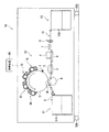
以下、図面を参照して本発明の第1実施形態について説明する。図1〜図4はいずれも本発明の第1実施形態にかかる液体トナー定着装置及び液体現像電子印刷機を説明するためのものであって、図1はその要部構成を模式的に示す図、図2は液体現像電子印刷機の概略構成を示す模式的な側面図、図3は現像ユニットの構成を模式的に示す図、図4は液体現像電子印刷機の動作手順を示すフローチャートである。
[First Embodiment]
Hereinafter, a first embodiment of the present invention will be described with reference to the drawings. 1 to 4 are all for explaining the liquid toner fixing device and the liquid developing electronic printer according to the first embodiment of the present invention, and FIG. 2 is a schematic side view showing a schematic configuration of the liquid developing electronic printing machine, FIG. 3 is a schematic diagram showing the configuration of the developing unit, and FIG. 4 is a flowchart showing an operation procedure of the liquid developing electronic printing machine. .
(全体構成)
図2に示すように、液体現像電子印刷機50は、給紙部51,印刷部52,排紙部53から構成されている。給紙部51は、被印刷物として枚葉紙である印刷シートSを1枚ずつ給紙トレイ51Aからシート搬送経路10の一部をなす印刷部52へと給紙するように構成されている。そして、印刷部52は給紙された印刷シートSに対して印刷を行うように構成され、排紙部53は印刷部52により印刷された印刷シートSを排紙トレイ53Aに排紙するように構成されている。なお、液体現像電子印刷機50の下部はキャスタ50Aが取り付けられており、液体現像電子印刷機50の移動を容易にするように構成されている。
(overall structure)
As shown in FIG. 2, the liquid developing
なお、図2に示すシート搬送経路10は、印刷シートSが搬送される経路(搬送ルート)を示しており、本実施形態では、給紙トレイ52Aからニップ部N1を通過後、ニップ部N2を通過し排紙トレイ53Aへ至るように構成されている。
また、液体現像電子印刷機50には、コンピュータ及び表示装置並びに入力端末を備えた制御装置60と信号線で接続されており、液体現像電子印刷機50の各部を制御信号により制御しうるように構成されている。なお、制御装置60を液体現像電子印刷機50に内蔵するように構成してもよい。
Note that a
Further, the liquid developing
(トナー転写部の概略構成)
本実施形態にかかる液体現像電子印刷機50はプロセスカラー印刷を行うことが可能に構成されており、印刷部52には、K(墨),C(藍),M(紅),Y(黄)のプロセスカラー各色に対応する4つの現像ユニット1A〜1Dがそなえられている。
印刷部52は、各現像ユニット1A〜1D,中間転写体2,ブレードユニット3,バックアップローラ4,被印刷物予加熱装置としてのオーブン(被印刷物予加熱手段,被印刷物昇温装置)5,キャリア除去装置としての閃光照射装置(キャリア除去手段,被印刷物昇温装置)6,ファン(送風機)7,一対の加熱ローラ(トナー定着手段)8及び搬送ベルト9を有して構成されている。
(Schematic configuration of toner transfer unit)
The liquid developing
The
各現像ユニット1A〜1Dは、中間転写体2の周囲に配設され、それぞれ制御装置60から送信された画像データに基づいて、感光体上に静電潜像の形成し、静電潜像に対応する位置に液体トナー20(図3も参照)を感光体11から中間転写体2に転写するように構成されている。なお、各現像ユニット1A〜1Dの詳細な構成については後述する。
なお、液体トナー20は、電荷が負荷された熱可塑性素材と色素素材(顔料あるいは染料)とにより形成されるトナー粒子が液体状のキャリア中に分散配合されたものであり、ここでは、パラフィン系の溶液に、平均粒径1μm程度のトナー粒子が重量比で20〜40パーセント程度含有されたものが用いられている。
Each of the developing
The
中間転写体2とバックアップローラ4とは互いに当接しており、当接部分にニップ部(転写位置)N1が形成されている。
中間転写体2の外周面は、例えば、ウレタン系導電性ゴムや導電性樹脂等で構成されており、中間転写体2には、例えば、−200〜−300V程度の中間転写バイアスが印加されている。
The
The outer peripheral surface of the
このニップ部N1において中間転写体2から印刷シートSに液体トナー20による画像が転写されるようになっている。
また、中間転写体2の周囲には、中間転写体2の回転方向でニップ部N1よりも下流側の位置にブレードユニット3が配設されており、印刷シートSに転写した後に中間転写体2の周面に残存した液体トナー20をブレードで掻き取って除去しうるように構成されている。
An image of the
In addition, a
一方、バックアップローラ4は、中間転写体2へ対して所定の圧力、例えば、1〜13kg/cm程度で圧力を加えるように配設されており、中間転写体2とバックアップローラ4との間を搬送される印刷シートSを中間転写体2に押付ける機能を有している。また、バックアップローラ4には、例えば、−800V程度の転写バイアスが印加されており、中間転写体2から印刷シートSへの液体トナー20の転写を促進するようになっている。
On the other hand, the backup roller 4 is arranged to apply a pressure to the
(トナー定着部周辺の構成)
以下、本発明の最も特徴的な部分であるトナーの印刷シートSへの定着にかかる装置構成について説明する。
中間転写体2とバックアップローラ4とのニップ部N1の下流側には、図1に示すように、オーブン5,閃光照射装置6,ファン7及び一対の加熱ローラ8がシート搬送経路10に沿って順に配設されている。
(Configuration around the toner fixing unit)
Hereinafter, an apparatus configuration relating to fixing of toner onto the print sheet S, which is the most characteristic part of the present invention, will be described.
As shown in FIG. 1, an
また、搬送ベルト9は、印刷シートSを載置した状態で搬送する無端ベルト(エンドレスベルト)により構成されており、ここでは、オーブン5及び閃光照射装置6の下部に2個配設されている。
オーブン5は、ここでは、ハロゲンランプを熱源とするハロゲンヒータによって構成されており、印刷シートSが閃光照射装置6を通過するのに先立って印刷シートSを摂氏130度〜150度程度の雰囲気にさらし、昇温させるように構成されている。これは、オーブン5により、あまり高温で加熱すると万一装置が停止した場合、オーブン5近傍に入っていた紙等の被印刷物が存在した場合余熱で発火する虞があるためである。
Further, the transport belt 9 is constituted by an endless belt (endless belt) that transports the print sheet S placed thereon. Here, two transport belts 9 are disposed below the
Here, the
なお、被印刷物予加熱手段としてはハロゲンヒータに限らず、赤外光あるいは熱風を照射するように構成してもよい。
閃光照射装置6は、キセノンフラッシュランプによって構成されており、図1に示すように、印刷シートSが閃光照射装置6の下部を搬送されるタイミングに合わせて印刷シートSの表面に瞬間的に閃光を照射させるようになっている。また、閃光照射装置6は瞬間的に印刷シートSを摂氏140度〜200度程度にまで昇温させるように閃光の出力が設定されている。
In addition, as a to-be-printed material preheating means, you may comprise so that infrared light or a hot air may be irradiated not only with a halogen heater.
The flash irradiation device 6 is constituted by a xenon flash lamp. As shown in FIG. 1, the flash irradiation device 6 instantaneously flashes on the surface of the print sheet S in accordance with the timing when the printing sheet S is conveyed below the flash irradiation device 6. Is supposed to be irradiated. Further, the flash irradiation device 6 is set to output a flash so as to instantaneously raise the temperature of the print sheet S to about 140 to 200 degrees Celsius.
ファン7は、印刷シートSのトナーが転写されている面から離れる向き(図1中、矢印Qが示す方向)に空気流を発生させるように配設されており、図示しないモータにより駆動するようになっている。これにより、シート搬送経路10周辺のファン7側の空気圧が周囲に対して負圧となるようになっている。
なお、閃光照射装置6の閃光照射タイミング及び出力並びにファン7の駆動は制御装置60によって制御されるようになっている。
The
The flash irradiation timing and output of the flash irradiation device 6 and the driving of the
また、ファン7は、シート搬送経路10の側方から側方から層状の空気流を形成するように配置して印刷シートSの上面側に負圧を形成するように構成してもよい。
加熱ローラ8は、一対のローラ8A,8Bによって構成されている。ローラ8Aは、表面に導電性フッ素コートが施された金属製のローラで、図示しない加熱源によって表面温度が、例えば、摂氏170度程度に設定されている。一方、ローラ8Bは、導電性を有するウレタンゴムで形成されている。
Further, the
The
なお、各ローラ8A,8B間には、印刷シートS上に転写されたキャリア中のトナーがローラ8A側に移動するような電場が形成されている。ここでは、ローラ8Aが接地されるとともにローラ8Bにトナーと同一極性の電荷が印加されている。
また、一対のローラ8A,8Bは互いに当接しており、印刷シートSが通過する際にローラ8A,8Bにより互いに印刷シートSを加圧しうるニップ部N2が形成されている。
An electric field is formed between the
The pair of
(現像ユニットの構成)
ここで、各現像ユニット1A〜1Dに詳細な構成について説明する。なお、各現像ユニット1A〜1Dはトナーの色と中間転写体2に対する配置位置を除いては同様に構成されているため、1つの現像ユニット(特に指定しない場合には以下、現像ユニット1と記載する)の構成についてのみ説明し、各現像ユニット1A〜1D毎の説明は省略する。
(Development unit configuration)
Here, a detailed configuration of each of the developing
現像ユニット1は、感光ドラム(感光体)11,クリーニングユニット12,除電器13,感光体帯電装置14,露光装置15及び現像装置16を有して構成されている。
感光ドラム11の周面には、アモルファスシリコン(a−Si)や感光性ポリマー等の感光剤を含んで形成された感光層11Aが形成されている。
感光ドラム11は、ニップ部N3において中間転写体2と当接しており、感光ドラム上の液体トナー20を中間転写体2側に転写しうるように構成されている。
The developing unit 1 includes a photosensitive drum (photosensitive member) 11, a
On the peripheral surface of the
The
一方、感光ドラム11の周囲には、ニップ部N3を起点として感光ドラム11の回転方向に沿って、クリーニングユニット12,除電器13,感光体帯電装置14,露光装置15及び現像装置19がそれぞれ順に感光層11Aに対向して配設されている。
クリーニングユニット12は、クリーニングローラ12A,ブレード12B,12C,トナー排出口12を有して構成されており、感光体11の周面に残存している液体トナー20を除去して図示しないトナー回収路に排出するように構成されている。
On the other hand, around the
The
より具体的に説明すると、クリーニングローラ12Aは、感光ドラム11に接して従動方向に回転するように配設されており、感光ドラム11の周面に残存する液体トナー20を回収するようになっている。
また、ブレード12Bは、弾性材料で形成された矩形状の板体であり、一方の長辺部が感光ドラム11の周面に接触するように配設されており、クリーニングローラ12Aで除去できなかった感光ドラム11周面の液体トナー20を掻き取って感光ドラム11から液体トナー20を完全に除去するようになっている。
More specifically, the cleaning
Further, the
ブレード12Cは、ブレード12Bと同様に弾性材料で形成された矩形状の板体であり、一方の長辺部がクリーニングローラ12Aの周面に接触するように配設されている。そして、クリーニングローラ12Aの周面に付着した液体トナー20を掻き取って除去するようになっている。
そして、感光ドラム11から除去された液体トナー20は、トナー排出口12から排出されるようになっている。
The blade 12C is a rectangular plate made of an elastic material like the
The
除電器13は、感光ドラム11の感光層11Aに残留する電荷を消去する機能を有している。
感光体帯電装置14は、コロトロン型あるいはスコロトン型等の非接触型放電方式の帯電器が感光ドラム11に沿って複数(ここでは3つ)配設されて構成されており、感光ドラム11の感光層11Aを一様に、例えば、500V程度に帯電させる機能を有している。
The
The photosensitive
露光装置15は、感光ドラム11の軸方向に沿って発光体(ここではLED)を棒状に配列された発光装置(つまりLEDアレイ)により構成されており、制御装置60から送られてくる画像データに基づいて、各LEDを発光させるようになっている。
つまり、感光体帯電装置14によって一様に帯電されている感光層11Aの表面に露光装置15からの光が照射されることにより、光の照射部分では感光層11Aの帯電が解除され、感光層11Aに画像データに基づいた静電潜像を形成しうるようになっている。
The
In other words, the light from the
なお、発光装置としては、LEDアレイの替わりに、画像データに基づいて半導体レーザー等を走査して静電潜像を形成するように構成してもよい。
現像装置16は、アニロックスローラ21,均しローラ22,現像ローラ23,トナー帯電器24,クリーニングローラ25,ブレード26,27,トナー供給口28及び液体トナー貯留部29を有して構成されており、感光ドラム11の静電潜像が形成された部分に液体トナー20を転写するようになっている。
Note that the light emitting device may be configured to form an electrostatic latent image by scanning a semiconductor laser or the like based on image data instead of the LED array.
The developing
トナー貯留部29には、液体トナー20が貯留されており、アニロックスローラ21の一部が液体トナー20に浸されるようにトナー供給口28から液体トナー20が適宜供給されるようになっている。
アニロックスローラ21は、金属製のローラでありその周面には表面には液体トナー20を所望の膜厚で供給するのに適した凹部(セル)が全面に亘って形成されている。アニロックスローラ25は、感光ドラム11と同方向(図3中の矢印の方向)に回転駆動されるようになっている。
The
また、ブレード27は板状の高密度ポリエチレンで形成されており、その先端がアニロックスローラ21の周面に接してアニロックスローラ21の周面に付着した液体トナー20を掻き落としてアニロックスローラ21の周面上の液体トナー20の膜厚を所望の膜厚にするように設定されている。
均しローラ22はウレタンゴムで形成されている。そして、均しローラ22はアニロックスローラ21と現像ローラ23との間に配設されており、アニロックスローラ21及び現像ローラ23のそれぞれと接している。
The
The leveling
また、均しローラ22は、アニロックスローラ21との接点において互いの周面が同じ方向に進む向き(図3中の矢印の方向)に回転するように構成されている。
現像ローラ23は導電性ゴムで形成されており、感光ドラム11と接してニップ部N4を形成するように配設されている。また、現像ローラ23は、ニップ部N4において感光ドラム11の周面と現像ローラ23の周面とが同じ方向に進む向き(図3中の矢印の方向)に回転するように構成されている。換言すると、現像ローラ23は均しローラ22との接点において互いの周面が反対方向に進む向きに回転するように構成されている。
Further, the leveling
The developing
また、現像ローラ23の周面の速度は感光ドラム11の周面の回転速度と同じ速度で回転するように構成されている。
このように、導電性を有する現像ローラ23と感光ドラム11とがニップ部N4で接することにより、現像ローラ23の周面から感光ドラム11の静電潜像が形成された部分へと帯電したトナー粒子を含む液体トナー20が転写され、現像が行われるようになっている。
The speed of the peripheral surface of the developing
As described above, the conductive developing
そして、現像された感光ドラム11の周面上の液体トナー20はニップ部N3において中間転写体2に転写され、中間転写体2の周面にトナー画像を形成するように構成されている。
なお、各現像ユニット1A〜1Dによってそれぞれ形成されるトナー画像は中間転写体2の周面の同位置に重なる位置であり、且つ、印刷シートSがニップ部N1を通過するタイミングに同期して、トナー画像が中間転写体2から印刷シートSの適切な位置に転写される位置に形成されるようになっている。
The developed
The toner images respectively formed by the developing
トナー帯電器24は、現像ローラ23の周面に近接しており、ニップ部N4よりも現像ローラ23の回転方向上流側、且つ、現像ローラ23と均しローラ22との接面よりもローラ23の回転方向下流側に位置するように配設されている。
トナー帯電器24は、コロトロン型あるいはスコロトン型等の非接触型放電方式の帯電器であり、現像ローラ24上の液体トナーを荷電する機能を有している。
The
The
クリーニングローラ25は、ニップ部N4よりも現像ローラ23の回転方向下流側において、現像ローラ23と接しており、感光体3へ転写されずに現像ローラ23の周面に残存した液体トナー20を除去するようになっている。
そしてブレード26は、クリーニングローラ25の周面に付着した液体トナー20を掻き落とすようになっている。
The cleaning
The
(作用効果)
本発明の第1実施形態にかかる液体トナー定着装置及び液体現像電子印刷機はこのように構成されているので、図4に示すように、まず、ステップS100では、制御装置60からの信号に基づいて印刷が開始され、印刷シートSが1枚だけ給紙トレイ51Aから印刷部52へと給紙される。
(Function and effect)
Since the liquid toner fixing device and the liquid developing electronic printer according to the first embodiment of the present invention are configured in this way, first, in step S100, based on the signal from the control device 60, as shown in FIG. Printing is started, and only one print sheet S is fed from the
そして、ステップS110では、印刷部53では、各現像ユニット1A〜1Dにより、中間転写体2の周面にK(墨),C(藍),M(紅),Y(黄)のプロセスカラーに対応する各液体トナー20が重合したトナー画像が形成される。
続いて、ステップS120では、ステップS100において給紙トレイ51Aから給紙された印刷シートSが中間転写体2とバックアップローラ4とにより形成されたニップ部N1を通過し、中間転写体2の周面から印刷シートSへと各色の液体トナー20(トナー画像)同時に転写される。
In step S110, in the
Subsequently, in step S120, the print sheet S fed from the
そして、ステップS130では、液体トナー20が転写された面が上面となるように印刷シートSが搬送ベルト9に載置された状態で搬送され、オーブン5により表面温度が摂氏50度〜110度程度にまで加熱される(被印刷物予加熱ステップ)。
そして、ステップS140では、搬送ベルト9に載置された印刷シートSに対して、閃光照射装置6により、閃光が照射され、印刷シートSの表面の画像部分(即ち、トナー部分)がさらに昇温される(閃光照射ステップ)。このとき、閃光による昇温による印刷シートSの表面温度は印刷シートS表面の画線率により異なり、ベタ部分(画線率100%)では摂氏160度以上である。非画像部は閃光によってはそれほど昇温されず、温度は低いが、トナーを定着させる必要がないないため、問題とならない。
In step S130, the printing sheet S is transported in a state of being placed on the transport belt 9 so that the surface to which the
In step S140, the flash irradiation device 6 irradiates the print sheet S placed on the conveyor belt 9 with flash light, and the temperature of the image portion (that is, the toner portion) on the surface of the print sheet S is further increased. (Flash exposure step). At this time, the surface temperature of the printing sheet S due to the temperature rise by the flash differs depending on the image line rate on the surface of the printing sheet S, and is 160 degrees Celsius or more in the solid portion (
なお、ステップS130及びステップS140が被印刷物昇温ステップに相当する。ステップS130及びS140により昇温された印刷シートS上の液体トナー20からは、熱により液体トナー20中のキャリアの蒸発量が大幅に増大される。
さらに、ステップS150では、ファン7により形成された負圧によりステップS130及びS140において昇温された印刷シートS上の液体トナー20からのキャリアの蒸発がさらに促進され、印刷シートS上に転写された液体トナー20中のキャリアが除去される。即ち、ここでは、ステップS130〜S150がキャリア除去ステップに相当する。
Note that step S130 and step S140 correspond to the substrate temperature raising step. From the
Further, in step S150, the evaporation of the carrier from the
ステップS150において印刷シートSがファン7の下部を通過し、加熱ローラ8のニップ部N2に差し掛かるとステップS160として、各ローラ8A,8B間に形成された電場によって、印刷シートS上の液体トナー20の内のトナーが加熱されたローラ8A側に引き寄せられる。そして、ニップ部N2において各ローラ8A,8Bにより加圧されるとともにローラ8Aによって加熱される。これにより、トナーが溶融した上で印刷シートSに押し付けられて印刷シートS上に定着(固定)される(トナー定着ステップ)。
In step S150, when the print sheet S passes through the lower portion of the
トナーが固定された印刷シートSはステップS170として排紙部53を搬送される間に冷却されて排紙トレイ53Aに排出される。
そして、ステップS180では、制御装置60において印刷終了条件が成立しているか否かが判定され、印刷終了条件が成立していない場合にはステップS100に戻り次の印刷シートSの印刷が行われる。また、ステップS180において、印刷終了条件が成立していればそのまま印刷が終了される。
In step S170, the print sheet S on which the toner is fixed is cooled while being conveyed through the
In step S180, the control device 60 determines whether or not a print end condition is satisfied. If the print end condition is not satisfied, the process returns to step S100 to print the next print sheet S. In step S180, if the printing end condition is satisfied, printing is ended as it is.
なお、印刷終了条件は、その都度、制御装置60の入力端末等により設定される。
このように、本発明の第1実施形態にかかる液体トナー定着装置及び液体現像電子印刷機並びに液体トナー定着方法によれば、一対の加熱ローラ8により印刷シートSが加圧及び加熱されるのに先立って液体トナー20中のトナーの印刷シートSに対する定着の阻害要因となるキャリアが蒸発することにより除去されるので、印刷シートSに対するトナーの定着性が向上され、より高品質の印刷物を得ることができる。
Note that the print end condition is set by the input terminal of the control device 60 each time.
As described above, according to the liquid toner fixing device, the liquid developing electronic printer, and the liquid toner fixing method according to the first embodiment of the present invention, the print sheet S is pressed and heated by the pair of
また、加熱ローラ8(ローラ8A)によってトナーを加熱し溶融させた上で溶融したトナーを被印刷物に押し付けることができるのでトナーの凹凸が均され、被印刷物に対して効果的にトナーを定着させることができる。このため、本発明の液体現像電子印刷機は、小ロット(数千枚程度)且つ他種類の印刷を高品質に行う場合に好適に適用できる。
また、閃光の照射(フラッシュ加熱)を行うことにシート搬送ライン10条において印刷シートSを瞬時に昇温させることができる。さらに、一定出力の閃光の照射により印刷シートSが昇温されるので、印刷シートSの搬送速度が多少変動した場合でも一定の熱量で印刷シートSを瞬時に昇温させることができる。
In addition, since the toner is heated and melted by the heating roller 8 (
Further, the temperature of the printed sheet S can be instantaneously increased in the
ただし、Xeランプ(キセノンランプ)を光源として構成される閃光照射装置6は、一般的に、印刷シートSの昇温にかかるエネルギ効率が良好とはいえない。しかし、閃光照射装置6によって印刷シートSの昇温を実行する前に、閃光照射装置6と比較してエネルギ効率のよいオーブン5によって印刷シートSを予め加熱しておくことで、閃光照射装置6の出力を抑制しても十分に液体トナー20中のキャリアを蒸発させることができ、全体としてのエネルギ効率を向上させることができる。
However, the flash irradiation device 6 configured using a Xe lamp (xenon lamp) as a light source is generally not good in energy efficiency for increasing the temperature of the printing sheet S. However, before the temperature of the printing sheet S is increased by the flash irradiation device 6, the flash irradiation device 6 is preheated by the
また、オーブン5及び閃光照射装置6の下流側においてファン7が印刷シートSから離れる方向に空気を送風するので、オーブン5及び閃光照射装置6により、昇温された印刷シートSの液体トナー20が転写された面(被印刷面)付近が周囲に対して負圧となり、印刷シートS中の水蒸気及びキャリアの蒸発をさらに促進させることができる。
また、一対の加熱ローラ8によってトナーを加熱し溶融させた上で溶融したトナーを印刷シートSの被印刷面に押し付けることができるので、印刷シートS上に定着されたトナーの凹凸が均され、印刷シートSに対するトナーの定着性を向上させることができる。
Further, since the
Further, since the toner is heated and melted by the pair of
また、中間転写体2とバックアップローラ4とで形成されるニップ部N1から一対の加熱ローラ8により形成されるニップ部N2までのシート搬送経路10において、印刷シートSを昇温させることにより液体状のキャリアの蒸発を促進させて効果的に除去することができる。また、一対の加熱ローラ8のニップ部N2を通過する前に印刷シートSが予め加熱されているので一対の加熱ローラ8において印刷シートSに加える熱量を低減することができる。
Further, in the
[第2実施形態]
続いて、本発明の第2実施形態について説明する。本実施形態は、一部の構成を除いて上述の第1実施形態と同様に構成されており、第1実施形態と同様のものについては説明を省略し、同符号を用いて説明する。
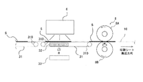
図5に示すように、本実施形態では、搬送ベルト(開口付搬送ベルト)31の構成及びその周辺にかかる構成が第1実施形態と異なっている。また、本実施形態では、第1実施形態おけるオーブン5及びファン7については省略して構成している。
[Second Embodiment]
Subsequently, a second embodiment of the present invention will be described. This embodiment is configured in the same manner as the above-described first embodiment except for a part of the configuration, and the description of the same components as those in the first embodiment will be omitted, and will be described using the same reference numerals.
As shown in FIG. 5, in the present embodiment, the configuration of the transport belt (transport belt with opening) 31 and the configuration related to the periphery thereof are different from those of the first embodiment. In the present embodiment, the
搬送ベルト31は、図6に示すように、複数の開口部31Bを有する載置ベルト(載置部)31が印刷シートSの幅方向に所定の間隔31Cを有して(即ち、間欠的に)並列するように構成され、2つのベルト駆動ローラ31D,31Dにより駆動される無端ベルトとして構成されている。
そして、図5に示すように、駆動ローラ31D,31Dによりシート搬送方向に駆動される載置ベルト31A(上段側の載置ベルト)とシート搬送方向逆向きに駆動される載置ベルト(下段側の載置ベルト)との間には、載置ベルト31Aを挟んで閃光照射装置6と対向する位置に吸引ファン(吸引手段)32が配設されている。
As shown in FIG. 6, the
Then, as shown in FIG. 5, the
吸引ファン32は、図5中矢印Rによって示される方向(印刷シートSから離れる方向)に空気流を発生させるように構成されている。
そして、吸引ファン32の送風方向には下段側の載置ベルト31Aを挟んでフィルタ33が配設されている。
フィルタ33は、印刷シートSから蒸発したキャリア(特にキャリア)を吸着するようになっている。
The
A filter 33 is arranged in the air blowing direction of the
The filter 33 sucks carriers (particularly carriers) evaporated from the printing sheet S.
なお、本実施形態では、第1実施形態におけるオーブン5を省略して構成しているため、閃光照射装置6の出力は第1実施形態のものよりも高出力に設定されている。
また、吸引ファン32の替わりにサクションボックスを配設し、サクションボックスにより吸引したものをフィルタ33に導入するように構成してもよい。
In this embodiment, since the
Further, a suction box may be provided in place of the
本発明の第2実施形態にかかる液体トナー定着装置及び液体現像電子印刷機は上述のように構成されているので、載置ベルト31Aの開口31B及び間隔31Cを通じて印刷シートSの搬送ベルト31側の面(以下、便宜上、裏面と呼ぶ)と外気との接触面積が増大するので、閃光照射装置6により昇温された印刷シートSの被印刷面からのみならず、裏面からのキャリア及び水蒸気の蒸発を促進させることになり、印刷シートSからのキャリアの蒸発をさらに効果的に促進させることができる。
Since the liquid toner fixing device and the liquid developing electronic printer according to the second embodiment of the present invention are configured as described above, the printing sheet S on the conveying
さらに、印刷シートSからの水蒸気及びキャリアは吸引ファン32により生じる空気流に沿って、フィルタ33に導かれフィルタ33により吸着されるので、有機溶媒であるキャリアが飛散することを抑制することができる。
Further, since the water vapor and the carrier from the printing sheet S are guided to the filter 33 and adsorbed by the filter 33 along the air flow generated by the
[第2実施形態の変形例]
続いて、本発明の第2実施形態の変形例について説明する。なお本変形例は、上述の第2実施形態とほぼ同様に構成されており、第2実施形態と同様のものについては説明を省略し、同符号を用いて説明する。
[Modification of Second Embodiment]
Then, the modification of 2nd Embodiment of this invention is demonstrated. Note that the present modification is configured in substantially the same manner as the second embodiment described above, and the description of the same components as those of the second embodiment will be omitted, and will be described using the same reference numerals.
本変形例では、搬送ベルト31の替わりに印刷シートSの両側端部を共に把持した状態で搬送するチェーングリッパ35を用いて構成している点のみが第2実施形態のものと異なっている。
図7に示すように、チェーングリッパ35は、図示しない2個の歯車により無端状に構成された2本のチェーン35A,35Aが2本平行に並列して配設されている。
The present modification is different from that of the second embodiment only in that the
As shown in FIG. 7, the
各チェーン35Aには、複数のグリッパ35Bが等間隔に取り付けられている。グリッパ35B間の間隔は、印刷シートSのシート搬送方向長さよりも短く設定されている。
グリッパ35Bは、印刷シートSの側端部を把持するように構成されており、図示しない掴み離し機構により、所定の搬送位置で印刷シートSを把持し、別の所定の位置で印刷シートSの把持を解除するようになっている。
A plurality of
The
本発明の第2実施形態の変形例にかかる液体トナー定着装置及び液体現像電子印刷機は上述のように構成されているので、第2実施形態のものよりもさらに印刷シートSの裏面と外気との接触面積が増大するので、印刷シートS中の水蒸気及び液体キャリアの蒸発をさらに促進させることができる。
また、吸引ファン32あるいはサクションボックスによる吸引によっての蒸発促進効果もより増大するという利点もある。
Since the liquid toner fixing device and the liquid developing electronic printer according to the modification of the second embodiment of the present invention are configured as described above, the back surface of the printing sheet S and the outside air are further increased than those of the second embodiment. Therefore, the evaporation of water vapor and liquid carrier in the printing sheet S can be further promoted.
Further, there is an advantage that the evaporation promotion effect by suction by the
さらに、印刷シートSの両面に印刷が可能な液体現像電子印刷機に適用した場合には、閃光照射装置6による閃光により、既にトナー定着されている既印刷面(裏面)のトナーが再び溶融することが生じた場合であっても、裏面のトナーが搬送ベルトに付着する等の不都合を回避することもできる。 Further, when applied to a liquid developing electronic printer capable of printing on both sides of the print sheet S, the toner on the already printed surface (back surface) on which the toner has already been fixed is melted again by the flash light from the flash light irradiation device 6. Even if this occurs, it is possible to avoid inconveniences such as toner on the back surface adhering to the conveying belt.
[その他の実施形態]
以上、本発明の実施形態について説明したが、本発明は上述の実施形態に限定されるものではなく、本発明の趣旨を逸脱しない範囲で種々変形して実施することができる。
例えば、第1実施形態における被印刷物予加熱手段(オーブン5),送風機(ファン7)等については適宜省略して構成してもよい。また、各実施形態及び変形例は、可能である限り適宜組み合わせて構成してもよい。例えば、第1実施形態の構成に第2実施形態及びその変形例にかかる搬送ベルトを設けるようにしてもよい。また、第1実施形態における送風機の送風方向にフィルタを配設して構成してもよい。
[Other Embodiments]
Although the embodiments of the present invention have been described above, the present invention is not limited to the above-described embodiments, and various modifications can be made without departing from the spirit of the present invention.
For example, the substrate preheating means (oven 5), the blower (fan 7), and the like in the first embodiment may be appropriately omitted. In addition, each embodiment and modification may be appropriately combined as long as possible. For example, you may make it provide the conveyance belt concerning 2nd Embodiment and its modification in the structure of 1st Embodiment. Moreover, you may comprise by arrange | positioning a filter in the ventilation direction of the air blower in 1st Embodiment.
さらに、上述の実施形態では、トナー定着手段としていずれも加熱ローラにより被印刷物を加熱及び加圧するように構成されているが、トナー定着手段としてはこれに限らず、被印刷物を単に加圧することによって被印刷物にトナーを定着させる加圧定着方式を適用してもよい。この場合でもトナーを定着させる前にトナー定着の阻害要因であるキャリアを除去することをトナーの定着性を向上させることができる。 Furthermore, in the above-described embodiment, the toner fixing unit is configured to heat and press the printed material by the heating roller. However, the toner fixing unit is not limited to this, and by simply pressing the printed material. A pressure fixing method for fixing toner on the substrate may be applied. Even in this case, it is possible to improve the toner fixability by removing the carrier which is an impediment to toner fixing before fixing the toner.
また、上述の実施形態では、被印刷物の一例として枚葉紙である印刷シートについて説明したが、被印刷物としては枚葉紙に限らず液体現像電子印刷機により印刷することが可能なものであるならば何にでも適用できる。例えば、枚葉紙の替わりに帯状の連続紙を被印刷物として連続的に印刷を行ってもよい。
なお、本発明にかかる液体現像電子印刷機は、印刷色数を限定するものではなく単色のみの印刷を行う印刷機として構成してもよいし、印刷シートの両面に印刷を行う両面印刷機に適用してもよい。
In the above-described embodiment, a printing sheet that is a sheet is described as an example of the printed material. However, the printed material is not limited to a sheet, and can be printed by a liquid development electronic printing machine. It can be applied to anything. For example, instead of a sheet, continuous printing may be performed using a continuous belt-like paper as a substrate.
The liquid developing electronic printing machine according to the present invention is not limited to the number of printing colors, and may be configured as a printing machine that performs printing of only a single color, or a double-sided printing machine that performs printing on both sides of a printing sheet. You may apply.
1,1A〜1D 現像ユニット
2 中間転写体
3 ブレードユニット
4 バックアップローラ
5 オーブン(被印刷物予加熱手段,被印刷物昇温装置)
6 閃光照射装置(被印刷物予加熱手段,被印刷物昇温装置)
7 ファン(送風機)
8 一対の加熱ローラ(トナー定着手段)
8A,8B ローラ
9 搬送ベルト
10 シート搬送経路
11 感光ドラム(感光体)
11A 感光層
12 クリーニングユニット
12B,12C ブレード
13 除電器
14 感光体帯電装置
15 露光装置
16 現像装置
20 液体トナー
21 アニロックスローラ
22 均しローラ
23 現像ローラ
24 トナー帯電器
25 クリーニングローラ
26,27 ブレード
28 トナー供給口
29 トナー貯留部
31A 載置ベルト
31B 開口
31C 間隔
31D ベルト駆動ローラ
32 吸引ファン
33フィルタ
35 チェーングリッパ
35A チェーン
35B グリッパ
50 液体現像電子印刷機
51 給紙部
51A 給紙トレイ
52 印刷部
53 排紙部
53A 排紙トレイ
60 制御装置
S 印刷シート
1, 1A to
6 Flash irradiation device (Substrate preheating means, Substrate heating device)
7 Fan (blower)
8 Pair of heating rollers (toner fixing means)
8A, 8B Roller 9 Conveying
Claims (19)
上記被印刷物に転写された上記液体トナーの内の上記トナーを上記被印刷物に定着させるトナー定着手段と、
上記トナー定着手段よりも上記被印刷物の搬送方向上流側に配設され、上記被印刷物に転写された上記液体トナーの内の上記キャリアを蒸発させて除去するキャリア除去手段とを有している
ことを特徴とする、液体トナー定着装置。 The developed toner image is transferred to the substrate by transferring the liquid toner in which the charged particulate toner is dispersed in the liquid carrier onto the photoconductor, and the liquid toner transferred to the substrate is transferred. A liquid toner fixing device for fixing the toner on the substrate,
Toner fixing means for fixing the toner in the liquid toner transferred to the substrate to the substrate;
A carrier removing unit disposed upstream of the toner fixing unit in the transport direction of the substrate and evaporating and removing the carrier of the liquid toner transferred to the substrate. A liquid toner fixing device.
上記液体トナーが転写された上記被印刷物を加熱及び加圧することにより上記液体トナーの内の上記トナーを上記被印刷物に定着させるように構成されている
ことを特徴とする、請求項1記載の液体トナー定着装置。 The toner fixing means is
2. The liquid according to claim 1, wherein the liquid toner is fixed to the substrate by heating and pressurizing the substrate to which the liquid toner is transferred. Toner fixing device.
上記液体トナーが転写された上記被印刷物を昇温させる被印刷物昇温装置を有している
ことを特徴とする、請求項1又は2記載の液体トナー定着装置。 The carrier removing means is
3. The liquid toner fixing device according to claim 1, further comprising a substrate temperature increasing device for increasing the temperature of the material to which the liquid toner is transferred.
上記液体トナーが転写された上記被印刷物に閃光を照射して上記被印刷物を昇温させる閃光照射装置を有している
ことを特徴とする、請求項3記載の液体トナー定着装置。 The substrate temperature raising apparatus is
4. The liquid toner fixing device according to claim 3, further comprising: a flash light irradiation device that irradiates the printed material to which the liquid toner has been transferred with flash light to raise the temperature of the printed material.
上記閃光照射装置よりも、上記シート搬送方向上流側に配設され、上記液体トナーが転写された上記被印刷物を予め昇温させる被印刷物予加熱手段を有している
ことを特徴とする、請求項4記載の液体トナー定着装置。 The substrate temperature raising apparatus is
The printed matter preheating means is provided on the upstream side in the sheet conveying direction from the flash irradiation device, and preheats the printed matter to which the liquid toner has been transferred. Item 5. The liquid toner fixing device according to Item 4.
上記トナー定着手段と上記被印刷物昇温装置との間に配設され上記被印刷物上のキャリアの蒸発を促進させるための送風機を有している
ことを特徴とする、請求項1〜5のいずれか1項に記載の液体トナー定着装置。 The carrier removing means is
6. A blower disposed between the toner fixing unit and the substrate temperature-elevating device for accelerating the evaporation of the carrier on the substrate. The liquid toner fixing device according to claim 1.
上記被印刷物は上記開口付搬送ベルト上に載置された状態で上記キャリア除去手段を搬送されるように構成されている
ことを特徴とする、請求項1〜6のいずれか1項に記載の液体トナー定着装置。 A carrying belt with an opening having an opening in the placement portion on which the substrate is placed;
The said to-be-printed material is comprised so that the said carrier removal means may be conveyed in the state mounted on the said conveyance belt with an opening, The any one of Claims 1-6 characterized by the above-mentioned. Liquid toner fixing device.
上記被印刷物は上記チェーングリッパに把持された状態で上記キャリア除去手段を搬送されるように構成されている
ことを特徴とする、請求項1〜6のいずれか1項に記載の液体トナー定着装置。 It has a chain gripper that conveys it while gripping the end of the substrate,
7. The liquid toner fixing device according to claim 1, wherein the substrate is transported by the carrier removing unit while being held by the chain gripper. 8. .
上記被印刷物昇温装置に対して上記被印刷物の搬送経路を挟んで対向して配設され上記被印刷物側からの空気を吸引する吸引手段を有している
ことを特徴とする、請求項7又は8記載の液体トナー定着装置。 The carrier removing means is
8. The apparatus according to claim 7, further comprising a suction unit that is disposed so as to face the substrate temperature raising device with a conveyance path of the substrate interposed therebetween and sucks air from the substrate side. Or the liquid toner fixing device according to 8.
帯電した上記液体トナーを静電潜像の形成された感光体上に転写することで現像を行う現像ユニットと、
上記感光体と上記被印刷物との間に配置され、上記感光体上の上記液体トナーを上記被印刷物に転写する中間転写体と、を有している
ことを特徴とする、液体現像電子印刷機。 A liquid toner fixing device according to any one of claims 1 to 9,
A developing unit that performs development by transferring the charged liquid toner onto a photoreceptor on which an electrostatic latent image is formed;
A liquid developing electronic printer comprising: an intermediate transfer member disposed between the photosensitive member and the substrate to transfer the liquid toner on the photosensitive member to the substrate. .
上記被印刷物に転写された上記液体トナーの内の上記トナーを上記被印刷物に定着させるトナー定着ステップと、
上記トナー定着ステップに先立って実行され上記被印刷物に転写された上記液体トナーの内の上記キャリアを蒸発させて除去するキャリア除去ステップとを有している
ことを特徴とする、液体トナー定着方法。 The developed toner image is transferred to the substrate by transferring the liquid toner in which the charged particulate toner is dispersed in the liquid carrier onto the photoconductor, and the liquid toner transferred to the substrate is transferred. A liquid toner fixing method for fixing the toner to the printing material,
A toner fixing step for fixing the toner in the liquid toner transferred to the substrate to the substrate;
A liquid toner fixing method, comprising: a carrier removing step of evaporating and removing the carrier of the liquid toner transferred to the substrate to be executed prior to the toner fixing step.
上記トナーが転写された上記被印刷物を加熱及び加圧することにより上記トナーを上記被印刷物に定着させる
ことを特徴とする、請求項11記載の液体トナー定着方法。 In the toner fixing step,
The liquid toner fixing method according to claim 11, wherein the toner is fixed to the printing material by heating and pressurizing the printing material to which the toner has been transferred.
上記液体トナーが転写された上記被印刷物を昇温させる被印刷物昇温ステップを有している
ことを特徴とする、請求項11又は12記載の液体トナー定着方法。 The carrier removal step includes
13. The liquid toner fixing method according to claim 11, further comprising a substrate temperature increasing step for increasing the temperature of the material to which the liquid toner is transferred.
上記液体トナーが転写された上記被印刷物に閃光を照射して上記被印刷物の温度を昇温させる閃光照射ステップを有している
ことを特徴とする、請求項13記載の液体トナー定着方法。 The substrate temperature raising step is
14. The liquid toner fixing method according to claim 13, further comprising a flash irradiation step of irradiating the substrate to which the liquid toner is transferred with flash to raise the temperature of the substrate.
上記閃光照射ステップに先立って、上記液体トナーが転写された上記被印刷物を予め昇温させる被印刷物予加熱ステップを有している
ことを特徴とする、請求項14記載の液体トナー定着方法。 The substrate temperature raising step is
15. The liquid toner fixing method according to claim 14, further comprising a pre-printing object heating step for preheating the printing medium to which the liquid toner has been transferred prior to the flash irradiation step.
上記被印刷物昇温ステップが実行されてから上記トナー定着ステップが実行される迄の間に上記被印刷物上に対して送風する送風ステップを有している
ことを特徴とする、請求項11〜15のいずれか1項に記載の液体トナー定着方法。 The carrier removal step includes
16. A blower step for blowing air on the print substrate between the execution of the temperature increase step of the print substrate and the execution of the toner fixing step. The liquid toner fixing method according to any one of the above.
上記被印刷物は、載置部に開口を有する開口付搬送ベルト上に載置された状態で搬送されている
ことを特徴とする、請求項11〜16のいずれか1項に記載の液体トナー定着方法。 In the carrier removal step,
The liquid toner fixing according to any one of claims 11 to 16, wherein the printing material is conveyed in a state of being placed on a conveying belt with an opening having an opening in a placing portion. Method.
上記被印刷物は、上記被印刷物の端部を把持するチェーングリッパに把持された状態で搬送されている
ことを特徴とする、請求項11〜16のいずれか1項に記載の液体トナー定着方法。 In the carrier removal step,
17. The liquid toner fixing method according to claim 11, wherein the printing material is conveyed in a state of being held by a chain gripper that holds an end portion of the printing material.
上記被印刷物昇温ステップと同時に実行され、上記被印刷物の搬送経路を挟んで反対側から空気を吸引する吸引ステップを有している
ことを特徴とする、請求項17又は18記載の液体トナー定着方法。 The carrier removal step includes
19. The liquid toner fixing according to claim 17, further comprising a suction step that is performed simultaneously with the substrate temperature raising step and sucks air from the opposite side across the conveyance path of the substrate. Method.
Priority Applications (1)
| Application Number | Priority Date | Filing Date | Title |
|---|---|---|---|
| JP2008001639A JP2009163065A (en) | 2008-01-08 | 2008-01-08 | Liquid toner fixing device, liquid-developing electronic printing machine and liquid toner fixing method |
Applications Claiming Priority (1)
| Application Number | Priority Date | Filing Date | Title |
|---|---|---|---|
| JP2008001639A JP2009163065A (en) | 2008-01-08 | 2008-01-08 | Liquid toner fixing device, liquid-developing electronic printing machine and liquid toner fixing method |
Publications (1)
| Publication Number | Publication Date |
|---|---|
| JP2009163065A true JP2009163065A (en) | 2009-07-23 |
Family
ID=40965739
Family Applications (1)
| Application Number | Title | Priority Date | Filing Date |
|---|---|---|---|
| JP2008001639A Withdrawn JP2009163065A (en) | 2008-01-08 | 2008-01-08 | Liquid toner fixing device, liquid-developing electronic printing machine and liquid toner fixing method |
Country Status (1)
| Country | Link |
|---|---|
| JP (1) | JP2009163065A (en) |
Cited By (14)
| Publication number | Priority date | Publication date | Assignee | Title |
|---|---|---|---|---|
| CN102193428A (en) * | 2010-03-12 | 2011-09-21 | 富士施乐株式会社 | Fixing device and image forming apparatus using the same |
| JP2012194340A (en) * | 2011-03-16 | 2012-10-11 | Konica Minolta Business Technologies Inc | Wet type image formation device |
| JP2013072893A (en) * | 2011-09-26 | 2013-04-22 | Fuji Xerox Co Ltd | Image forming method and image forming device |
| JP2013113898A (en) * | 2011-11-25 | 2013-06-10 | Konica Minolta Business Technologies Inc | Fixing device and image forming device |
| WO2014209123A1 (en) * | 2013-06-28 | 2014-12-31 | Xeikon Ip Bv | Digital printing apparatus and printing process |
| JP2015018043A (en) * | 2013-07-09 | 2015-01-29 | 富士ゼロックス株式会社 | Fixing device and image forming apparatus |
| JP2015020417A (en) * | 2013-07-23 | 2015-02-02 | セイコーエプソン株式会社 | Recording device and drying method |
| JP2015024636A (en) * | 2013-07-29 | 2015-02-05 | セイコーエプソン株式会社 | Recording device and drying method |
| US9465332B1 (en) | 2015-08-05 | 2016-10-11 | Fuji Xerox Co., Ltd. | Fixing device and image forming apparatus |
| WO2020158011A1 (en) * | 2019-01-31 | 2020-08-06 | 富士ゼロックス株式会社 | Fixing device and image formation device |
| WO2020170471A1 (en) * | 2019-02-20 | 2020-08-27 | 富士ゼロックス株式会社 | Image forming device |
| WO2020183757A1 (en) * | 2019-03-12 | 2020-09-17 | 富士ゼロックス株式会社 | Fixing device and image-forming apparatus |
| WO2020261615A1 (en) * | 2019-06-25 | 2020-12-30 | 富士ゼロックス株式会社 | Heating device and image forming device |
| WO2021005929A1 (en) * | 2019-07-10 | 2021-01-14 | 富士ゼロックス株式会社 | Fixing device and image forming device |
-
2008
- 2008-01-08 JP JP2008001639A patent/JP2009163065A/en not_active Withdrawn
Cited By (38)
| Publication number | Priority date | Publication date | Assignee | Title |
|---|---|---|---|---|
| CN102193428B (en) * | 2010-03-12 | 2015-09-09 | 富士施乐株式会社 | The image processing system of fixing device and use fixing device |
| CN102193428A (en) * | 2010-03-12 | 2011-09-21 | 富士施乐株式会社 | Fixing device and image forming apparatus using the same |
| JP2012194340A (en) * | 2011-03-16 | 2012-10-11 | Konica Minolta Business Technologies Inc | Wet type image formation device |
| US8867950B2 (en) | 2011-03-16 | 2014-10-21 | Konica Minolta Business Technologies, Inc. | Wet-type image forming apparatus |
| JP2013072893A (en) * | 2011-09-26 | 2013-04-22 | Fuji Xerox Co Ltd | Image forming method and image forming device |
| JP2013113898A (en) * | 2011-11-25 | 2013-06-10 | Konica Minolta Business Technologies Inc | Fixing device and image forming device |
| WO2014209123A1 (en) * | 2013-06-28 | 2014-12-31 | Xeikon Ip Bv | Digital printing apparatus and printing process |
| NL2012525C2 (en) * | 2013-06-28 | 2015-01-05 | Xeikon Ip B V | Digital printing apparatus and printing process. |
| US9588464B2 (en) | 2013-06-28 | 2017-03-07 | Xeikon IP B.V. | Digital printing apparatus and printing process |
| JP2015018043A (en) * | 2013-07-09 | 2015-01-29 | 富士ゼロックス株式会社 | Fixing device and image forming apparatus |
| JP2015020417A (en) * | 2013-07-23 | 2015-02-02 | セイコーエプソン株式会社 | Recording device and drying method |
| JP2015024636A (en) * | 2013-07-29 | 2015-02-05 | セイコーエプソン株式会社 | Recording device and drying method |
| US9465332B1 (en) | 2015-08-05 | 2016-10-11 | Fuji Xerox Co., Ltd. | Fixing device and image forming apparatus |
| WO2020158011A1 (en) * | 2019-01-31 | 2020-08-06 | 富士ゼロックス株式会社 | Fixing device and image formation device |
| JP2020122932A (en) * | 2019-01-31 | 2020-08-13 | 富士ゼロックス株式会社 | Fixing device and image forming apparatus |
| CN113272741B (en) * | 2019-01-31 | 2023-09-29 | 富士胶片商业创新有限公司 | Fixing device and image forming apparatus |
| US11300902B2 (en) | 2019-01-31 | 2022-04-12 | Fujifilm Business Innovation Corp. | Fixing device having preheating unit, blowing unit and image forming apparatus |
| CN113272741A (en) * | 2019-01-31 | 2021-08-17 | 富士胶片商业创新有限公司 | Fixing device and image forming apparatus |
| JP7139979B2 (en) | 2019-01-31 | 2022-09-21 | 富士フイルムビジネスイノベーション株式会社 | Fixing device, image forming device |
| WO2020170471A1 (en) * | 2019-02-20 | 2020-08-27 | 富士ゼロックス株式会社 | Image forming device |
| JP7404853B2 (en) | 2019-02-20 | 2023-12-26 | 富士フイルムビジネスイノベーション株式会社 | Image forming device |
| US11385582B2 (en) | 2019-02-20 | 2022-07-12 | Fujifilm Business Innovation Corp. | Image forming device |
| JP2022167980A (en) * | 2019-03-12 | 2022-11-04 | 富士フイルムビジネスイノベーション株式会社 | Fixing device and image forming apparatus |
| WO2020183757A1 (en) * | 2019-03-12 | 2020-09-17 | 富士ゼロックス株式会社 | Fixing device and image-forming apparatus |
| US11940745B2 (en) | 2019-03-12 | 2024-03-26 | Fujifilm Business Innovation Corp. | Fixing device and image forming apparatus |
| JP7131688B2 (en) | 2019-03-12 | 2022-09-06 | 富士フイルムビジネスイノベーション株式会社 | Fixing device and image forming device |
| JPWO2020183757A1 (en) * | 2019-03-12 | 2021-11-04 | 富士フイルムビジネスイノベーション株式会社 | Fixing device and image forming device |
| JP7447948B2 (en) | 2019-03-12 | 2024-03-12 | 富士フイルムビジネスイノベーション株式会社 | Fixing device and image forming device |
| US11493864B2 (en) | 2019-03-12 | 2022-11-08 | Fujifilm Business Innovation Corp. | Fixing device and image forming apparatus |
| US11880148B2 (en) | 2019-06-25 | 2024-01-23 | Fujifilm Business Innovation Corp. | Heating device and image forming apparatus |
| WO2020261615A1 (en) * | 2019-06-25 | 2020-12-30 | 富士ゼロックス株式会社 | Heating device and image forming device |
| CN113993801A (en) * | 2019-06-25 | 2022-01-28 | 富士胶片商业创新有限公司 | Heating device and image forming apparatus |
| JP7443783B2 (en) | 2019-06-25 | 2024-03-06 | 富士フイルムビジネスイノベーション株式会社 | Heating device and image forming device |
| CN113993801B (en) * | 2019-06-25 | 2024-04-09 | 富士胶片商业创新有限公司 | Heating device and image forming apparatus |
| US11740575B2 (en) | 2019-07-10 | 2023-08-29 | Fujifilm Business Innovation Corp. | Fixing device and image forming apparatus |
| JP7447642B2 (en) | 2019-07-10 | 2024-03-12 | 富士フイルムビジネスイノベーション株式会社 | Fixing device, image forming device |
| WO2021005929A1 (en) * | 2019-07-10 | 2021-01-14 | 富士ゼロックス株式会社 | Fixing device and image forming device |
| CN113994272A (en) * | 2019-07-10 | 2022-01-28 | 富士胶片商业创新有限公司 | Fixing device and image forming apparatus |
Similar Documents
| Publication | Publication Date | Title |
|---|---|---|
| JP2009163065A (en) | Liquid toner fixing device, liquid-developing electronic printing machine and liquid toner fixing method | |
| CN104865808B (en) | Image processing system | |
| JP2007310220A (en) | Fixing device and image forming apparatus equipped therewith | |
| JPH11231598A (en) | Color image recording device | |
| WO2009088047A1 (en) | Duplex printer and duplex printing method for liquid developing electrophotography | |
| JP2011175208A (en) | Intermediate transfer blanket and intermediate transfer body for electrophotographic printing | |
| US9025990B2 (en) | Printer vapor treatment preheating | |
| JP2006350099A (en) | Fixing device, image forming apparatus, and fixing method | |
| JP2011175209A (en) | Electrophotographic printer | |
| JP4557072B2 (en) | Image forming apparatus | |
| US20120114344A1 (en) | Image Forming Apparatus | |
| JP2009007096A (en) | Medium conveying device and image forming device | |
| JP6040571B2 (en) | Image forming apparatus | |
| JP3903877B2 (en) | Image forming apparatus | |
| JP2011175112A (en) | Fixing device for electrophotographic printing, and electrophotographic printer | |
| JP2007219246A (en) | Fixing device and image forming apparatus equipped with the same | |
| WO2009088077A1 (en) | Carrier removing device and carrier removing method of liquid-development electronic printer | |
| JP2797208B2 (en) | Image forming device | |
| JP5203527B2 (en) | Printing section and electrophotographic printing apparatus | |
| JP2010072371A (en) | Fixing device and fixing method, and electrophotographic printer | |
| JP2021149013A (en) | Conveyance device and printing device | |
| JP5077401B2 (en) | Image forming apparatus | |
| KR100403594B1 (en) | Image drying unit for liquid electrophotographic printer | |
| JP2007226080A (en) | Wet fixing device and image forming apparatus with same | |
| JP2012150344A (en) | Carrier removal roller and electrophotographic printer |
Legal Events
| Date | Code | Title | Description |
|---|---|---|---|
| A300 | Withdrawal of application because of no request for examination |
Free format text: JAPANESE INTERMEDIATE CODE: A300 Effective date: 20110405 |