JP2009156772A - Surveying system - Google Patents
Surveying system Download PDFInfo
- Publication number
- JP2009156772A JP2009156772A JP2007337109A JP2007337109A JP2009156772A JP 2009156772 A JP2009156772 A JP 2009156772A JP 2007337109 A JP2007337109 A JP 2007337109A JP 2007337109 A JP2007337109 A JP 2007337109A JP 2009156772 A JP2009156772 A JP 2009156772A
- Authority
- JP
- Japan
- Prior art keywords
- target
- surveying
- unit
- position data
- movement amount
- Prior art date
- Legal status (The legal status is an assumption and is not a legal conclusion. Google has not performed a legal analysis and makes no representation as to the accuracy of the status listed.)
- Pending
Links
Images


Classifications
-
- G—PHYSICS
- G01—MEASURING; TESTING
- G01C—MEASURING DISTANCES, LEVELS OR BEARINGS; SURVEYING; NAVIGATION; GYROSCOPIC INSTRUMENTS; PHOTOGRAMMETRY OR VIDEOGRAMMETRY
- G01C15/00—Surveying instruments or accessories not provided for in groups G01C1/00 - G01C13/00
- G01C15/002—Active optical surveying means
-
- E—FIXED CONSTRUCTIONS
- E02—HYDRAULIC ENGINEERING; FOUNDATIONS; SOIL SHIFTING
- E02F—DREDGING; SOIL-SHIFTING
- E02F3/00—Dredgers; Soil-shifting machines
- E02F3/04—Dredgers; Soil-shifting machines mechanically-driven
- E02F3/76—Graders, bulldozers, or the like with scraper plates or ploughshare-like elements; Levelling scarifying devices
- E02F3/80—Component parts
- E02F3/84—Drives or control devices therefor, e.g. hydraulic drive systems
- E02F3/841—Devices for controlling and guiding the whole machine, e.g. by feeler elements and reference lines placed exteriorly of the machine
- E02F3/842—Devices for controlling and guiding the whole machine, e.g. by feeler elements and reference lines placed exteriorly of the machine using electromagnetic, optical or photoelectric beams, e.g. laser beams
-
- E—FIXED CONSTRUCTIONS
- E02—HYDRAULIC ENGINEERING; FOUNDATIONS; SOIL SHIFTING
- E02F—DREDGING; SOIL-SHIFTING
- E02F9/00—Component parts of dredgers or soil-shifting machines, not restricted to one of the kinds covered by groups E02F3/00 - E02F7/00
- E02F9/26—Indicating devices
-
- G—PHYSICS
- G01—MEASURING; TESTING
- G01S—RADIO DIRECTION-FINDING; RADIO NAVIGATION; DETERMINING DISTANCE OR VELOCITY BY USE OF RADIO WAVES; LOCATING OR PRESENCE-DETECTING BY USE OF THE REFLECTION OR RERADIATION OF RADIO WAVES; ANALOGOUS ARRANGEMENTS USING OTHER WAVES
- G01S17/00—Systems using the reflection or reradiation of electromagnetic waves other than radio waves, e.g. lidar systems
- G01S17/02—Systems using the reflection of electromagnetic waves other than radio waves
- G01S17/06—Systems determining position data of a target
-
- G—PHYSICS
- G01—MEASURING; TESTING
- G01S—RADIO DIRECTION-FINDING; RADIO NAVIGATION; DETERMINING DISTANCE OR VELOCITY BY USE OF RADIO WAVES; LOCATING OR PRESENCE-DETECTING BY USE OF THE REFLECTION OR RERADIATION OF RADIO WAVES; ANALOGOUS ARRANGEMENTS USING OTHER WAVES
- G01S17/00—Systems using the reflection or reradiation of electromagnetic waves other than radio waves, e.g. lidar systems
- G01S17/66—Tracking systems using electromagnetic waves other than radio waves
-
- G—PHYSICS
- G01—MEASURING; TESTING
- G01S—RADIO DIRECTION-FINDING; RADIO NAVIGATION; DETERMINING DISTANCE OR VELOCITY BY USE OF RADIO WAVES; LOCATING OR PRESENCE-DETECTING BY USE OF THE REFLECTION OR RERADIATION OF RADIO WAVES; ANALOGOUS ARRANGEMENTS USING OTHER WAVES
- G01S7/00—Details of systems according to groups G01S13/00, G01S15/00, G01S17/00
- G01S7/003—Transmission of data between radar, sonar or lidar systems and remote stations
Abstract
Description
本発明は測量システム、特に追尾機能を有する測量装置を使用した測量システムに関するものである。 The present invention relates to a surveying system, and more particularly to a surveying system using a surveying device having a tracking function.
従来より距離測定、水平角、鉛直角の測定を行う測量装置として、追尾機能を有する測量装置があり、斯かる測量装置では、該測量装置が具備する視準望遠鏡によりコーナキューブ等の対象反射体(ターゲット)を視準し、前記視準望遠鏡から追尾光を射出し、ターゲットが移動した場合には、ターゲットからの反射光を受光する様にして、ターゲットを自動的に追尾する様になっている。 Conventionally, as a surveying device for measuring distance, horizontal angle, and vertical angle, there is a surveying device having a tracking function, and in such a surveying device, a target reflector such as a corner cube is provided by a collimating telescope included in the surveying device. (Target) is collimated, and tracking light is emitted from the collimating telescope. When the target moves, the reflected light from the target is received and the target is automatically tracked. Yes.
通常、追尾機能を有する測量装置では測量装置側は無人で、作業者はターゲット側で作業する。ターゲットは作業者によって支持され、或は建設機械に支持されて移動する。 Usually, in a surveying instrument having a tracking function, the surveying instrument side is unattended, and an operator works on the target side. The target is supported by an operator or moved by a construction machine.
ターゲットの移動速度が測量装置の追従速度を超え、視準望遠鏡の視野からターゲットが外れてしまったり、或は測量装置とターゲットとの間に一時的に木、車、人等の障害物が入り、障害物が視準望遠鏡の光路を遮断した場合には、測量装置はターゲットからの反射光を受光することができず、自動追尾が中断することがある。 The moving speed of the target exceeds the tracking speed of the surveying instrument, and the target moves out of the field of view of the collimating telescope, or obstacles such as trees, cars, and people temporarily enter between the surveying instrument and the target. When the obstacle blocks the optical path of the collimating telescope, the surveying instrument cannot receive the reflected light from the target, and automatic tracking may be interrupted.
これは、一般的な視準望遠鏡では、画角(視野角)が約1°と小さい為であり、自動追尾の為の反射光の検出範囲が小さいことに起因している。 This is because a general collimating telescope has a small angle of view (viewing angle) of about 1 °, and is caused by a small detection range of reflected light for automatic tracking.
自動追尾が中断すると、測量装置はターゲットを探索(サーチ)する動作を開始するが、探索動作は追尾光を射出した状態で視準望遠鏡を上下方向、左右方向に所定範囲回転させることで走査し、ターゲットを検出する。 When automatic tracking is interrupted, the surveying instrument starts an operation to search for a target. The search operation is performed by rotating the collimating telescope up and down and left and right within a predetermined range while emitting tracking light. , Detect the target.
従来のサーチ方法としては、測量装置側で視準望遠鏡により最後に検出した位置を基準として所定の水平角の範囲で高低角を変えながら走査する(図6(A))、或は、最後に検出した位置から渦巻状に走査する(図6(B))等して見失ったターゲット12を検出している。
As a conventional search method, scanning is performed while changing the elevation angle within a predetermined horizontal angle range based on the position finally detected by the collimating telescope on the surveying instrument side (FIG. 6A), or finally The
上記した様に、視準望遠鏡の視野角は小さいので、ターゲットを再検出するには、走査ピッチを細かくする必要がある。この為、自動追尾が中断した場合には、再度ターゲットを検出し、自動追尾が開始できる様になるには多大な時間を要していた。更に、障害物による光路の遮断が頻繁に生じる作業環境では、測定の作業効率が著しく低下するという問題があった。 As described above, since the viewing angle of the collimating telescope is small, it is necessary to reduce the scanning pitch in order to redetect the target. For this reason, when the automatic tracking is interrupted, it takes a long time to detect the target again and to start the automatic tracking. Furthermore, there is a problem that the working efficiency of measurement is remarkably lowered in a working environment in which an optical path is frequently blocked by an obstacle.
尚、追尾機能を有し、追尾が中断した場合にサーチを行う測量装置としては、特許文献1に示されるものがある。
A surveying device that has a tracking function and performs a search when tracking is interrupted is disclosed in
本発明は斯かる実情に鑑み、追尾機能を有する測量装置を備えた測量システムに於いて、ターゲットを見失い、自動追尾不能な状態となった場合に、前記ターゲットの再検出が迅速に行え、自動追尾に復帰する時間を短縮して測定作業の効率を向上させるものである。 In view of such circumstances, the present invention provides a survey system equipped with a surveying device having a tracking function. When the target is lost and automatic tracking becomes impossible, the target can be quickly re-detected. It shortens the time to return to tracking and improves the efficiency of measurement work.
本発明は、ターゲットに向け測距光を照射して測距、測角を行い前記ターゲットの3次元位置データが測定可能であり、前記ターゲットの追尾機能を有する測量装置と、前記ターゲット側に設けられる可動側制御装置とを具備し、前記測量装置は、該測量装置で測定した前記ターゲットの3次元位置データを前記可動側制御装置に送信可能な通信手段と、前記測量装置のターゲットのサーチを制御する第1制御演算部とを有し、前記可動側制御装置は、前記ターゲットの移動量検出手段と、該移動量検出手段からのターゲット検出信号に基づき前記ターゲットの移動量を演算し、該ターゲットの移動量、及び前記3次元位置データに基づきターゲット位置を演算する第2制御演算部とを有し、前記測量装置が前記ターゲットを追尾不能となった場合に前記可動側制御装置から送信される前記ターゲット位置を取得し、前記第1制御演算部は該ターゲット位置を起点として前記ターゲットのサーチを開始する様構成した測量システムに係り、又ターゲットに向け測距光を照射して測距、測角を行い前記ターゲットの3次元位置データが測定可能であり、前記ターゲットの追尾機能を有する測量装置と、前記ターゲット側に設けられる可動側制御装置とを具備し、前記測量装置は、該測量装置で測定した前記ターゲットの3次元位置データを前記可動側制御装置に送信可能な通信手段と、前記測量装置のターゲットのサーチを制御する第1制御演算部とを有し、前記可動側制御装置は、前記ターゲットの移動量検出手段と、該移動量検出手段からのターゲット検出信号に基づき前記ターゲットの移動量を演算する第2制御演算部とを有し、前記測量装置が前記ターゲットを追尾不能となった場合に前記可動側制御装置から送信されるターゲット移動量を取得し、前記第1制御演算部は最後に測定した前記ターゲットの3次元位置データと、前記ターゲット移動量に基づきターゲット位置を演算し、該ターゲット位置を起点として前記ターゲットのサーチを開始する様構成した測量システムに係り、更に又前記移動量検出手段は、加速度センサである測量システムに係るものである。 The present invention provides a surveying apparatus capable of measuring the three-dimensional position data of the target by irradiating the target with a distance measuring light to measure the distance and the angle, and has a tracking function of the target, and is provided on the target side. A movable side control device, and the surveying device is capable of transmitting the three-dimensional position data of the target measured by the surveying device to the movable side control device, and searching for the target of the surveying device. A first control calculation unit for controlling, the movable side control device calculates a movement amount of the target based on a target movement amount detection unit and a target detection signal from the movement amount detection unit, A second control calculation unit that calculates a target position based on the amount of movement of the target and the three-dimensional position data, and the surveying instrument becomes unable to track the target The target position transmitted from the movable side control device is acquired, and the first control calculation unit relates to a surveying system configured to start searching for the target starting from the target position. A surveying device capable of measuring the three-dimensional position data of the target by irradiating ranging light and measuring the distance and angle, and having a tracking function of the target, and a movable side control device provided on the target side The surveying device includes a communication unit capable of transmitting the three-dimensional position data of the target measured by the surveying device to the movable-side control device, and a first control arithmetic unit that controls the search of the target of the surveying device The movable-side control device includes a target movement amount detection means and a target detection signal based on the target detection signal from the movement amount detection means. A second control calculation unit for calculating the movement amount of the robot, and when the surveying device becomes unable to track the target, obtains a target movement amount transmitted from the movable control device, A control calculation unit relates to a surveying system configured to calculate a target position based on the last measured three-dimensional position data of the target and the target movement amount, and to start searching for the target using the target position as a starting point. Furthermore, the movement amount detecting means relates to a surveying system which is an acceleration sensor.
本発明によれば、ターゲットに向け測距光を照射して測距、測角を行い前記ターゲットの3次元位置データが測定可能であり、前記ターゲットの追尾機能を有する測量装置と、前記ターゲット側に設けられる可動側制御装置とを具備し、前記測量装置は、該測量装置で測定した前記ターゲットの3次元位置データを前記可動側制御装置に送信可能な通信手段と、前記測量装置のターゲットのサーチを制御する第1制御演算部とを有し、前記可動側制御装置は、前記ターゲットの移動量検出手段と、該移動量検出手段からのターゲット検出信号に基づき前記ターゲットの移動量を演算し、該ターゲットの移動量、及び前記3次元位置データに基づきターゲット位置を演算する第2制御演算部とを有し、前記測量装置が前記ターゲットを追尾不能となった場合に前記可動側制御装置から送信される前記ターゲット位置を取得し、前記第1制御演算部は該ターゲット位置を起点として前記ターゲットのサーチを開始する様構成したので、得られたターゲット位置は現在位置、或は現在位置に略近いものであり、サーチ範囲は最小でターゲットの検出が可能となり、追尾開始が直ちにできるという優れた効果を発揮する。 According to the present invention, it is possible to measure a distance and an angle by irradiating ranging light toward a target, and to measure the three-dimensional position data of the target, the surveying device having a tracking function of the target, and the target side The surveying device comprises a communication means capable of transmitting the three-dimensional position data of the target measured by the surveying device to the movable control device, and a target of the surveying device. A first control calculation unit that controls a search, and the movable side control device calculates a movement amount of the target based on a movement amount detection unit of the target and a target detection signal from the movement amount detection unit. A second control calculation unit that calculates a target position based on the amount of movement of the target and the three-dimensional position data, and the surveying instrument cannot track the target The target position transmitted from the movable side control device is acquired in the case, and the first control calculation unit is configured to start searching for the target starting from the target position. Is the current position or substantially close to the current position, the search range is minimum, the target can be detected, and the excellent effect that tracking can be started immediately is exhibited.
又本発明によれば、ターゲットに向け測距光を照射して測距、測角を行い前記ターゲットの3次元位置データが測定可能であり、前記ターゲットの追尾機能を有する測量装置と、前記ターゲット側に設けられる可動側制御装置とを具備し、前記測量装置は、該測量装置で測定した前記ターゲットの3次元位置データを前記可動側制御装置に送信可能な通信手段と、前記測量装置のターゲットのサーチを制御する第1制御演算部とを有し、前記可動側制御装置は、前記ターゲットの移動量検出手段と、該移動量検出手段からのターゲット検出信号に基づき前記ターゲットの移動量を演算する第2制御演算部とを有し、前記測量装置が前記ターゲットを追尾不能となった場合に前記可動側制御装置から送信されるターゲット移動量を取得し、前記第1制御演算部は最後に測定した前記ターゲットの3次元位置データと、前記ターゲット移動量に基づきターゲット位置を演算し、該ターゲット位置を起点として前記ターゲットのサーチを開始する様構成したので、得られたターゲット位置は現在位置、或は現在位置に略近いものであり、サーチ範囲は最小でターゲットの検出が可能となり、追尾開始が直ちにできるという優れた効果を発揮する。 According to the present invention, it is also possible to measure the distance and angle of the target by irradiating the target with the distance measuring light, to measure the three-dimensional position data of the target, and to have the tracking function of the target, the target A movable side control device provided on the side, wherein the surveying device is capable of transmitting three-dimensional position data of the target measured by the surveying device to the movable side control device, and a target of the surveying device A first control calculation unit that controls the search of the target, and the movable-side control device calculates the target movement amount based on the target movement amount detection means and a target detection signal from the movement amount detection means. A second control calculation unit that acquires a target movement amount transmitted from the movable control device when the surveying device becomes unable to track the target, 1 control calculation unit is configured to calculate the target position based on the last measured three-dimensional position data of the target and the target movement amount, and to start searching for the target from the target position. The target position is the current position or substantially close to the current position, the search range is minimum, the target can be detected, and an excellent effect that tracking can be started immediately is exhibited.
更に、本発明によれば、前記移動量検出手段は、加速度センサであるので、安価な検出器で移動量検出手段を構成することができるという優れた効果を発揮する。 Furthermore, according to the present invention, since the movement amount detection means is an acceleration sensor, the movement amount detection means can be configured with an inexpensive detector.
以下、図面を参照しつつ本発明を実施する為の最良の形態を説明する。 The best mode for carrying out the present invention will be described below with reference to the drawings.
先ず、図1〜図3に於いて、本発明が実施される測量システムの概略を説明する。 First, an outline of a survey system in which the present invention is implemented will be described with reference to FIGS.
図1は本発明に係る測量システムの一例を示しており、本発明が建設機械10、例えばブルドーザによる土木作業に使用される場合を示している。
FIG. 1 shows an example of a surveying system according to the present invention, and shows a case where the present invention is used for civil engineering work by a
測量装置1は三脚11を介して既知点に設置され、ターゲット12及び可動側制御装置16は排土板13に立設されたポール14に設けられている。
The
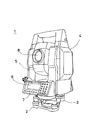
図2は本発明が実施される測量装置1を示している。尚、用いられる測量装置1は、例えばトータルステーションであり、測定点に向ってパルスレーザ光線を照射し、前記測定点からのパルス反射光を受光して、各パルス毎に測距を行い、測距結果を平均化して高精度の距離測定を行うものである。
FIG. 2 shows a
前記測量装置1は主に、前記三脚11(図1参照)に取付けられる整準部2、該整準部2に設けられた基盤部3、該基盤部3に鉛直軸心を中心に回転可能に設けられた托架部4、該托架部4に水平軸心を中心に回転可能に設けられた望遠鏡部5から構成されている。
The
前記托架部4は第1表示部6、第1操作入力部7を具備し、前記望遠鏡部5は、測定対象物を視準する望遠鏡8を具備すると共に該望遠鏡8と光学系を共有する測距部21(後述)を具備している。
The
前記測量装置1は通信手段として第1無線部15を具備し、前記測量装置1で測定した、前記ターゲット12迄の距離、該ターゲット12について水平角、鉛直角を測定し、これら測定して得られた測距、測角の測定データ(3次元位置データ)を前記ターゲット12側に無線送信する様になっている。
The
該ターゲット12側には可動側制御装置16が設置される。該可動側制御装置16は、前記ポール14に取付けられ、或は前記建設機械10に装備される(図1中では、前記ポール14に設けられている)。
A movable
前記可動側制御装置16は、前記測量装置1との間でデータ通信を行う為の通信部を具備し、又前記測量装置1から受信した3次元位置データを基に前記ターゲット12の移動方向、移動距離を求める位置測定手段を具備している。
The movable
図3により、本発明に係る測量システムの概略の構成について説明する。 A schematic configuration of the surveying system according to the present invention will be described with reference to FIG.
測量システムは主に、前記測量装置1と前記ターゲット12、前記可動側制御装置16から構成されている。
The surveying system mainly includes the
先ず、前記測量装置1について説明する。
First, the
前記望遠鏡部5は、測距光学系を有する測距部21を内蔵し、該測距部21は測距光22を射出すると共に前記ターゲット12からの反射光22′を受光して該ターゲット12迄の光波距離測定を行う。又、前記測距光学系を共通の光学系とした撮像部23を具備している。
The
前記托架部4には、該托架部4を水平方向に回転させる為の水平駆動部24が設けられると共に前記托架部4の前記基盤部3に対する水平回転角を検出し、視準方向の水平角を検出する水平測角部25が設けられる。又前記托架部4には、水平軸心を中心に前記望遠鏡部5を回転する鉛直駆動部26が設けられると共に前記望遠鏡部5の鉛直角を検出し、視準方向の鉛直角を測角する鉛直測角部27が設けられる。尚、前記測距部21、前記水平測角部25、前記鉛直測角部27は測定部を構成する。
The
前記托架部4には制御装置28が内蔵され、前記水平駆動部24、前記鉛直駆動部26の駆動を制御して前記托架部4、前記望遠鏡部5を回転して前記望遠鏡部5を所定の方向に向け(視準し)、又所定の範囲を走査し、前記望遠鏡8の光学倍率の切換えを行い、或は前記撮像部23による視準方向の画像の取得、更に取得画像の電気的処理倍率の切換えを制御して、所要の倍率の画像を取得する。更に、前記測距部21を制御して前記ターゲット12迄の測距を行う。
The
又、第1制御演算部29は、前記測距部21が前記ターゲット12からの前記反射光22′を受光し、測距している状態かどうか、即ち追尾中であるかどうかの判断を行う。
The first
前記撮像部23は受光素子(図示せず)を具備し、該受光素子は、例えば画素の集合体であるCCD、CMOS等であり、受光する画素の位置が特定でき、画像処理部31は画素からの信号に基づき、該画素の画角を求め、更に前記ターゲット12の位置を演算する様になっている。
The
前記制御装置28は、主に前記第1制御演算部29、測距制御部30、前記画像処理部31、第1記憶部32、前記第1表示部6、前記第1操作入力部7、前記第1無線部15等から構成されている。
The
又、前記第1制御演算部29には前記測距部21、前記水平測角部25、前記鉛直測角部27からの測定結果が入力され、距離測定、水平角、鉛直角の測定が行われ、得られた測定データ(3次元位置データ)は前記第1制御演算部29を介して前記第1記憶部32に格納されると共に前記第1表示部6に表示される様になっている。又、前記第1制御演算部29は、前記画像処理部31からの信号に基づき前記ターゲット12が視準の中心になる様に前記水平駆動部24、前記鉛直駆動部26を駆動して追尾を行い。前記測距制御部30を制御して測距を行う。
The first
追尾中であるかどうかの判断結果、及び前記測定データは前記第1無線部15より前記可動側制御装置16に送信される。
The determination result as to whether tracking is in progress and the measurement data are transmitted from the
前記第1記憶部32には、各種プログラムを格納するプログラム格納領域と、測定結果等のデータを格納するデータ格納領域とを有し、前記プログラム格納領域には測定に必要な計算プログラム、或は後述する画像処理によりターゲット12の位置を検出する画像処理プログラム、測定点(ターゲット)を追尾するシーケンスプログラム、測定を開始する際に、又前記ターゲット12を見失った場合に該ターゲット12を探索する為のサーチプログラム、画像を前記第1表示部6に表示する為の画像表示プログラム、前記可動側制御装置16との間で通信を行う為の通信プログラム等のプログラムが格納されている。
The
次に、前記可動側制御装置16について説明する。
Next, the movable
該可動側制御装置16は、主に第2制御演算部35、第2記憶部36、第2無線部37、移動量検出手段38等から構成されている。
The movable
前記第2記憶部36には、前記測量装置1と無線通信を行う為の通信プログラム、前記移動量検出手段38からの信号に基づき移動方向、移動距離を演算する位置算出プログラム等のプログラムが格納されている。又、前記第2記憶部36は一部にデータ格納部を有し、該データ格納部には前記測量装置1から送信された測定データ、前記位置算出プログラムによって算出された前記ターゲット12の位置データが記憶される様になっている。
The
前記移動量検出手段38は、例えば加速度センサであり、前記ターゲット12に作用する加速度を検出する。前記第2制御演算部35は前記移動量検出手段38からの加速度信号に基づき加速度を積分し、速度、更に距離を演算し、所定時点からの移動方向、移動距離を演算し、演算結果は前記第2記憶部36に記憶される。
The movement amount detection means 38 is an acceleration sensor, for example, and detects an acceleration acting on the
前記第2無線部37は、前記測量装置1から送信される前記ターゲット12の3次元位置データを受信し、受信されたデータは前記第2記憶部36に格納される。
The
以下、図4、図5を参照して本発明の作動について説明する。尚、図4は前記測量装置1のシーケンス、図5は前記ターゲット12、前記可動側制御装置16のシーケンスを示している。
The operation of the present invention will be described below with reference to FIGS. 4 shows the sequence of the surveying
測定点に前記ターゲット12を設置し、前記測量装置1の電源を投入する。
The
先ず、前記測量装置1の作動について説明する。
First, the operation of the
STEP:01 前記望遠鏡8により前記ターゲット12を追尾可能な範囲に捉える。又、前記撮像部23により前記ターゲット12の像が受光される。
(Step 01) The
STEP:02 前記ターゲット12の像を基に前記画像処理部31によってターゲット位置が求められ、前記望遠鏡8が前記ターゲット12に視準される。
(Step 02) The target position is determined by the
STEP:03 前記望遠鏡8が前記ターゲット12に視準されることで、距離測定、水平角、鉛直角が測定され、前記ターゲット12についての3次元位置データが得られる。又、追尾が行われ、測定が続行される。又、前記ターゲット12の3次元位置データも所定時間間隔、例えば0.1秒、或は0.05秒間隔で、前記第1無線部15を介して前記可動側制御装置16に送信される。
(Step 03) When the
STEP:04 前記ターゲット12からの反射光22′が途絶えた場合、或は前記ターゲット12以外からの反射光が入射した場合等は、追尾が継続可能か、或は不可能かが判断され、継続可能であれば、引続き追尾が行われると共に3次元位置データが前記可動側制御装置16に送信される(STEP:08)。
(Step 04) When the reflected light 22 'from the
STEP:05 追尾が不可能である場合、即ち、3次元位置データが送信できない場合は、前記測量装置1は待機状態となり、前記可動側制御装置16からターゲット位置データが送信されることを待つ。
(Step 05) When tracking is impossible, that is, when the three-dimensional position data cannot be transmitted, the
STEP:06、STEP:07 前記可動側制御装置16からターゲット位置データを受信すると、該位置データを起点として、前記ターゲット12のサーチを開始する。サーチする態様としては、図6(A)、図6(B)のいずれか、或は任意の態様が採用可能である。
STEP: 06, STEP: 07 When the target position data is received from the movable
受信するターゲットの位置は、追尾不能となった最後のターゲットの位置を前記可動側制御装置16で修正したものであり、見失ったターゲットは受信したターゲットの位置の近傍にあると考えられ、サーチ距離、或はサーチ範囲は最小限で済み、短時間でターゲット12の検出が可能となる。
The position of the target to be received is the position of the last target that has become untrackable, corrected by the movable
又、前記STEP:02に於いて前記ターゲット12が検出されると、前記STEP:03以降の工程が繰返し実行される。
When the
次に、前記ターゲット12、前記可動側制御装置16の作動について説明する。
Next, the operation of the
STEP:11 測定が開始され、前記測量装置1から前記ターゲット12の測定結果、即ち該ターゲット12の3次元位置データが所定時間間隔で送信され、前記第2無線部37が3次元位置データを受信する。
STEP: 11 Measurement is started, the measurement result of the
STEP:12 受信された前記3次元位置データは、前記第2記憶部36に記憶される。更に、前記移動量検出手段38からは継続的に加速度信号が入力されており、該加速度信号に基づき前記第2制御演算部35は前記3次元位置データを受信した時点からの方向、距離(移動距離)を演算し、前記3次元位置データに該移動距離を加算して、前記ターゲット12の3次元位置データをリアルタイムで算出する。移動距離の演算は次の3次元位置データを受信する迄継続して行われ、次の3次元位置データを受信した時点で移動距離の演算が再スタートし、前回で演算された移動距離及び受信した3次元位置データが書換えられる。
STEP: 12 The received three-dimensional position data is stored in the
STEP:13 前記第2無線部37は、所定時間内に前記測量装置1から3次元位置データを受信した場合、受信有りの信号を前記第2制御演算部35に出力し、該第2制御演算部35は所定時間内に前記3次元位置データを受信したかどうかを判断する。
(Step 13) When the
所定時間内に該3次元位置データを受信したと判断した場合は、追尾が継続されていると判断されると共に受信した前記3次元位置データ及び前記移動量検出手段38からの信号に基づき前記ターゲット12の現在位置(ターゲット位置データ)が算出される(STEP:12)。 When it is determined that the three-dimensional position data is received within a predetermined time, it is determined that tracking is continued, and the target is determined based on the received three-dimensional position data and the signal from the movement amount detection means 38. Twelve current positions (target position data) are calculated (STEP: 12).
STEP:14 所定時間内に3次元位置データを受信しなかったと判断した場合は、最後に算出した前記ターゲット12の3次元位置データが前記第2記憶部36から呼込まれ、前記第2無線部37を介して前記ターゲット12のターゲット位置データが前記測量装置1に送信される。
STEP: 14 When it is determined that the three-dimensional position data has not been received within a predetermined time, the last calculated three-dimensional position data of the
上記した様に、該測量装置1は前記ターゲット12のターゲット位置データを受信すると、該ターゲット12のターゲット位置データを基準としてサーチを開始する(STEP:06、STEP:07)。
As described above, when receiving the target position data of the
尚、上記実施の形態では、建設機械にターゲット12、可動側制御装置16を設けたが、測量作業者が支持するポールにターゲット12、可動側制御装置16を取付け、作業者がポールを移動させる形態にも実施可能であることは言う迄もない。
In the above embodiment, the construction machine is provided with the
又、前記移動量検出手段38として加速度センサを挙げたが、その他ジャイロ、モーションセンサ、GPS位置検出装置等が使用可能である。
Although the acceleration sensor is mentioned as the movement
又、前記測量装置1が前記ターゲット12を見失ったことの判断は、前記可動側制御装置16側で行ってもよく、前記測量装置1からの3次元位置データを所定時間受信しなかった場合、追尾不能状態と判断してもよい。更に、前記可動側制御装置16から前記測量装置1へのターゲット位置データは、前記可動側制御装置16で追尾不能状態と判断したことをトリガーとして前記測量装置1に送信してもよく、或は前記測量装置1が追尾不能状態と判断したときに、前記可動側制御装置16にターゲット位置データを要求することで、送信する様にしてもよい。
Further, the determination that the
又、前記測量装置1が前記ターゲット12を見失ったことの判断は、前記測量装置1が前記ターゲット12からの反射光22′を受光できなくなったこと、或は前記ターゲット12についての測距が行えなくなったことで判断してもよい。更に、前記撮像部23で受光したターゲット12の像が追尾可能な範囲から外れたことで見失ったと判断してもよい。
In addition, the determination that the surveying
更に又、前記可動側制御装置16は前記移動量検出手段38からの信号に基づきターゲット12の移動方向、移動量のみを演算し、前記測量装置1が追尾不能となった場合、前記移動方向、移動量を前記測量装置1に送信し、該測量装置1は受信した前記ターゲット12の移動方向、移動量と、最後に測定した該ターゲット12の3次元位置データより現在の該ターゲット12の位置を演算し、演算で得た該ターゲット12の位置を起点としてターゲットのサーチを開始してもよい。
Furthermore, the movable
更に又、通信手段としては、無線通信、光通信のいずれの方法であってもよい。 Furthermore, the communication means may be either wireless communication or optical communication.
1 測量装置
2 整準部
5 望遠鏡部
8 望遠鏡
10 建設機械
11 三脚
12 ターゲット
15 第1無線部
16 可動側制御装置
21 測距部
22 測距光
29 第1制御演算部
35 第2制御演算部
37 第2無線部
38 移動量検出手段
DESCRIPTION OF
Claims (3)
Priority Applications (5)
| Application Number | Priority Date | Filing Date | Title |
|---|---|---|---|
| JP2007337109A JP2009156772A (en) | 2007-12-27 | 2007-12-27 | Surveying system |
| US12/315,358 US7701566B2 (en) | 2007-12-27 | 2008-12-02 | Surveying system |
| EP08171154.1A EP2083245B1 (en) | 2007-12-27 | 2008-12-10 | Surveying system |
| CNA2008101844702A CN101470204A (en) | 2007-12-27 | 2008-12-25 | Surveying system |
| CN201410818527.5A CN104808215A (en) | 2007-12-27 | 2008-12-25 | Surveying system |
Applications Claiming Priority (1)
| Application Number | Priority Date | Filing Date | Title |
|---|---|---|---|
| JP2007337109A JP2009156772A (en) | 2007-12-27 | 2007-12-27 | Surveying system |
Publications (1)
| Publication Number | Publication Date |
|---|---|
| JP2009156772A true JP2009156772A (en) | 2009-07-16 |
Family
ID=40482033
Family Applications (1)
| Application Number | Title | Priority Date | Filing Date |
|---|---|---|---|
| JP2007337109A Pending JP2009156772A (en) | 2007-12-27 | 2007-12-27 | Surveying system |
Country Status (4)
| Country | Link |
|---|---|
| US (1) | US7701566B2 (en) |
| EP (1) | EP2083245B1 (en) |
| JP (1) | JP2009156772A (en) |
| CN (2) | CN101470204A (en) |
Cited By (5)
| Publication number | Priority date | Publication date | Assignee | Title |
|---|---|---|---|---|
| CN103392533A (en) * | 2013-07-04 | 2013-11-20 | 北京农业智能装备技术研究中心 | Bed arranging machine and control method thereof |
| KR20140042920A (en) * | 2011-09-13 | 2014-04-07 | 헥사곤 테크놀로지 센터 게엠베하 | Geodetic surveying system and method with multiple target tracking functionality |
| JP2014224790A (en) * | 2013-05-17 | 2014-12-04 | 株式会社ミツトヨ | Tracking laser device |
| JP2019039867A (en) * | 2017-08-28 | 2019-03-14 | 株式会社トプコン | Position measurement device, position measurement method and program for position measurement |
| JP2022185210A (en) * | 2021-06-02 | 2022-12-14 | 空撮サービス株式会社 | Unmanned aerial vehicle position measurement system, and position measurement method |
Families Citing this family (30)
| Publication number | Priority date | Publication date | Assignee | Title |
|---|---|---|---|---|
| US9482755B2 (en) | 2008-11-17 | 2016-11-01 | Faro Technologies, Inc. | Measurement system having air temperature compensation between a target and a laser tracker |
| CN101852857B (en) * | 2009-03-30 | 2013-07-17 | 株式会社拓普康 | Surveying device and automatic tracking method |
| CA2766428C (en) * | 2009-06-23 | 2017-05-23 | Leica Geosystems Ag | Tracking method and measuring system having a laser tracker |
| KR101196326B1 (en) * | 2009-10-15 | 2012-11-01 | 한국전자통신연구원 | Apparatus and method for estimating position of objects |
| US8537371B2 (en) | 2010-04-21 | 2013-09-17 | Faro Technologies, Inc. | Method and apparatus for using gestures to control a laser tracker |
| US9772394B2 (en) | 2010-04-21 | 2017-09-26 | Faro Technologies, Inc. | Method and apparatus for following an operator and locking onto a retroreflector with a laser tracker |
| US8422034B2 (en) * | 2010-04-21 | 2013-04-16 | Faro Technologies, Inc. | Method and apparatus for using gestures to control a laser tracker |
| US9400170B2 (en) | 2010-04-21 | 2016-07-26 | Faro Technologies, Inc. | Automatic measurement of dimensional data within an acceptance region by a laser tracker |
| US8724119B2 (en) | 2010-04-21 | 2014-05-13 | Faro Technologies, Inc. | Method for using a handheld appliance to select, lock onto, and track a retroreflector with a laser tracker |
| US8619265B2 (en) | 2011-03-14 | 2013-12-31 | Faro Technologies, Inc. | Automatic measurement of dimensional data with a laser tracker |
| US9377885B2 (en) | 2010-04-21 | 2016-06-28 | Faro Technologies, Inc. | Method and apparatus for locking onto a retroreflector with a laser tracker |
| GB2518544A (en) | 2011-03-03 | 2015-03-25 | Faro Tech Inc | Target apparatus and method |
| JP2014516409A (en) | 2011-04-15 | 2014-07-10 | ファロ テクノロジーズ インコーポレーテッド | Improved position detector for laser trackers. |
| US9482529B2 (en) | 2011-04-15 | 2016-11-01 | Faro Technologies, Inc. | Three-dimensional coordinate scanner and method of operation |
| US9164173B2 (en) | 2011-04-15 | 2015-10-20 | Faro Technologies, Inc. | Laser tracker that uses a fiber-optic coupler and an achromatic launch to align and collimate two wavelengths of light |
| US9686532B2 (en) | 2011-04-15 | 2017-06-20 | Faro Technologies, Inc. | System and method of acquiring three-dimensional coordinates using multiple coordinate measurement devices |
| US8655556B2 (en) * | 2011-09-30 | 2014-02-18 | Komatsu Ltd. | Blade control system and construction machine |
| US9222771B2 (en) | 2011-10-17 | 2015-12-29 | Kla-Tencor Corp. | Acquisition of information for a construction site |
| US9638507B2 (en) | 2012-01-27 | 2017-05-02 | Faro Technologies, Inc. | Measurement machine utilizing a barcode to identify an inspection plan for an object |
| EP2639549A1 (en) * | 2012-03-15 | 2013-09-18 | Leica Geosystems AG | Laser receiver |
| EP2639548A1 (en) * | 2012-03-15 | 2013-09-18 | Leica Geosystems AG | Laser Receiver capable to detect its own Movements |
| US9866322B2 (en) * | 2012-03-15 | 2018-01-09 | Leica Geosystems Ag | Laser receiver |
| US9041914B2 (en) | 2013-03-15 | 2015-05-26 | Faro Technologies, Inc. | Three-dimensional coordinate scanner and method of operation |
| CN105829220A (en) * | 2013-11-06 | 2016-08-03 | 米-杰克产品股份有限公司 | Dynamic sensor system and method |
| US9395174B2 (en) | 2014-06-27 | 2016-07-19 | Faro Technologies, Inc. | Determining retroreflector orientation by optimizing spatial fit |
| CN106595654A (en) * | 2016-12-13 | 2017-04-26 | 天津大学 | Continuous tracking measurement method and device for laser tracking measurement system |
| WO2018233826A1 (en) * | 2017-06-21 | 2018-12-27 | Trimble Ab | Method, processing unit and surveying instrument for improved tracking of a target |
| JP6867244B2 (en) * | 2017-06-28 | 2021-04-28 | 株式会社トプコン | Surveying instrument communication management system |
| JP7289239B2 (en) * | 2019-07-26 | 2023-06-09 | 株式会社トプコン | surveying system |
| DE102020126817A1 (en) | 2020-10-13 | 2022-04-14 | Valeo Schalter Und Sensoren Gmbh | MEASUREMENT ARRANGEMENT AND MEASUREMENT METHOD |
Citations (7)
| Publication number | Priority date | Publication date | Assignee | Title |
|---|---|---|---|---|
| JPH04283614A (en) * | 1991-03-12 | 1992-10-08 | Toa Harbor Works Co Ltd | Three-dimensional surveying apparatus |
| JPH11211459A (en) * | 1997-11-13 | 1999-08-06 | Carl Zeiss:Fa | Surveying system with inertia protecting measuring means |
| JP2001033250A (en) * | 1999-07-21 | 2001-02-09 | Sokkia Co Ltd | Surveying device |
| JP2002005660A (en) * | 2000-06-26 | 2002-01-09 | Sokkia Co Ltd | Remotely operated surveying system |
| JP2004108939A (en) * | 2002-09-18 | 2004-04-08 | Pentax Precision Co Ltd | Remote control system of survey airplane |
| JP2004132914A (en) * | 2002-10-11 | 2004-04-30 | Topcon Corp | Position measuring apparatus |
| JP2006242755A (en) * | 2005-03-03 | 2006-09-14 | Sokkia Co Ltd | Surveying system |
Family Cites Families (13)
| Publication number | Priority date | Publication date | Assignee | Title |
|---|---|---|---|---|
| US5000564A (en) * | 1990-03-09 | 1991-03-19 | Spectra-Physics, Inc. | Laser beam measurement system |
| US5100229A (en) * | 1990-08-17 | 1992-03-31 | Spatial Positioning Systems, Inc. | Spatial positioning system |
| US6198528B1 (en) * | 1998-05-22 | 2001-03-06 | Trimble Navigation Ltd | Laser-based three dimensional tracking system |
| US6227761B1 (en) * | 1998-10-27 | 2001-05-08 | Delaware Capital Formation, Inc. | Apparatus and method for three-dimensional contouring |
| US6519029B1 (en) * | 1999-03-22 | 2003-02-11 | Arc Second, Inc. | Low cost transmitter with calibration means for use in position measurement systems |
| JP4320099B2 (en) * | 1999-03-26 | 2009-08-26 | 株式会社トプコン | Surveying equipment |
| JP4229350B2 (en) | 1999-09-28 | 2009-02-25 | ケミカルグラウト株式会社 | Propulsion orbit correction device |
| JP2003149342A (en) | 2001-11-09 | 2003-05-21 | Penta Ocean Constr Co Ltd | Moving body positioning method and device using satellite positioning and light wave positioning system |
| JP3937154B2 (en) * | 2002-06-28 | 2007-06-27 | 株式会社トプコン | Position detection device |
| US7168174B2 (en) * | 2005-03-14 | 2007-01-30 | Trimble Navigation Limited | Method and apparatus for machine element control |
| JP5466806B2 (en) * | 2006-09-21 | 2014-04-09 | 株式会社トプコン | Optical distance measurement method, distance measurement program, and distance measurement apparatus |
| CN101627319A (en) * | 2007-03-08 | 2010-01-13 | 特林布尔公司 | The method and the instrument that are used for estimating target motion |
| JP5124319B2 (en) * | 2008-03-21 | 2013-01-23 | 株式会社トプコン | Surveying instrument, surveying system, measuring object detection method, and measuring object detection program |
-
2007
- 2007-12-27 JP JP2007337109A patent/JP2009156772A/en active Pending
-
2008
- 2008-12-02 US US12/315,358 patent/US7701566B2/en active Active
- 2008-12-10 EP EP08171154.1A patent/EP2083245B1/en active Active
- 2008-12-25 CN CNA2008101844702A patent/CN101470204A/en active Pending
- 2008-12-25 CN CN201410818527.5A patent/CN104808215A/en active Pending
Patent Citations (7)
| Publication number | Priority date | Publication date | Assignee | Title |
|---|---|---|---|---|
| JPH04283614A (en) * | 1991-03-12 | 1992-10-08 | Toa Harbor Works Co Ltd | Three-dimensional surveying apparatus |
| JPH11211459A (en) * | 1997-11-13 | 1999-08-06 | Carl Zeiss:Fa | Surveying system with inertia protecting measuring means |
| JP2001033250A (en) * | 1999-07-21 | 2001-02-09 | Sokkia Co Ltd | Surveying device |
| JP2002005660A (en) * | 2000-06-26 | 2002-01-09 | Sokkia Co Ltd | Remotely operated surveying system |
| JP2004108939A (en) * | 2002-09-18 | 2004-04-08 | Pentax Precision Co Ltd | Remote control system of survey airplane |
| JP2004132914A (en) * | 2002-10-11 | 2004-04-30 | Topcon Corp | Position measuring apparatus |
| JP2006242755A (en) * | 2005-03-03 | 2006-09-14 | Sokkia Co Ltd | Surveying system |
Cited By (6)
| Publication number | Priority date | Publication date | Assignee | Title |
|---|---|---|---|---|
| KR20140042920A (en) * | 2011-09-13 | 2014-04-07 | 헥사곤 테크놀로지 센터 게엠베하 | Geodetic surveying system and method with multiple target tracking functionality |
| KR101632225B1 (en) | 2011-09-13 | 2016-06-21 | 헥사곤 테크놀로지 센터 게엠베하 | Geodetic surveying system and method with multiple target tracking functionality |
| JP2014224790A (en) * | 2013-05-17 | 2014-12-04 | 株式会社ミツトヨ | Tracking laser device |
| CN103392533A (en) * | 2013-07-04 | 2013-11-20 | 北京农业智能装备技术研究中心 | Bed arranging machine and control method thereof |
| JP2019039867A (en) * | 2017-08-28 | 2019-03-14 | 株式会社トプコン | Position measurement device, position measurement method and program for position measurement |
| JP2022185210A (en) * | 2021-06-02 | 2022-12-14 | 空撮サービス株式会社 | Unmanned aerial vehicle position measurement system, and position measurement method |
Also Published As
| Publication number | Publication date |
|---|---|
| CN104808215A (en) | 2015-07-29 |
| US20090171618A1 (en) | 2009-07-02 |
| US7701566B2 (en) | 2010-04-20 |
| EP2083245A2 (en) | 2009-07-29 |
| EP2083245B1 (en) | 2016-02-24 |
| CN101470204A (en) | 2009-07-01 |
| EP2083245A3 (en) | 2010-08-04 |
Similar Documents
| Publication | Publication Date | Title |
|---|---|---|
| JP2009156772A (en) | Surveying system | |
| JP5469894B2 (en) | Surveying device and automatic tracking method | |
| JP5150229B2 (en) | Surveying system | |
| US11822351B2 (en) | Three-dimensional information processing unit, apparatus having three-dimensional information processing unit, unmanned aerial vehicle, informing device, method and program for controlling mobile body using three-dimensional information processing unit | |
| EP2503284B1 (en) | Survey system with survey apparatus, survey pole and mobile wireless transceiver system | |
| JP4354343B2 (en) | Position measurement system | |
| US10048063B2 (en) | Measuring instrument and surveying system | |
| KR100892147B1 (en) | Gis system | |
| JP6336837B2 (en) | Surveying equipment | |
| CA2867562A1 (en) | Three-dimensional measuring method and surveying system | |
| EP1503176A2 (en) | Survey guiding system | |
| EP3514489B1 (en) | Surveying device and surveying method | |
| JP7257326B2 (en) | Surveying instrument, surveying system, surveying method and surveying program | |
| JP2009229350A (en) | Survey system | |
| JP6346011B2 (en) | Surveying equipment | |
| JP6823482B2 (en) | 3D position measurement system, 3D position measurement method, and measurement module | |
| US11725938B2 (en) | Surveying apparatus, surveying method, and surveying program | |
| JP7355484B2 (en) | 3D surveying equipment and 3D surveying method | |
| US9932719B2 (en) | Control system for construction machine | |
| KR20120064348A (en) | The apparatus and method of topography measuring | |
| JP2016206130A (en) | Three-dimensional position measurement system | |
| JP2021063760A (en) | Surveying system | |
| KR100892153B1 (en) | Surveying system | |
| JP2018155589A (en) | Autonomous movement controller, mobile entity, autonomous movement control method, and program | |
| JP4422927B2 (en) | Survey method in civil engineering work |
Legal Events
| Date | Code | Title | Description |
|---|---|---|---|
| A621 | Written request for application examination |
Free format text: JAPANESE INTERMEDIATE CODE: A621 Effective date: 20101203 |
|
| A977 | Report on retrieval |
Free format text: JAPANESE INTERMEDIATE CODE: A971007 Effective date: 20120719 |
|
| A131 | Notification of reasons for refusal |
Free format text: JAPANESE INTERMEDIATE CODE: A131 Effective date: 20120724 |
|
| A02 | Decision of refusal |
Free format text: JAPANESE INTERMEDIATE CODE: A02 Effective date: 20121113 |