JP2009148045A - Leak current reducing device - Google Patents
Leak current reducing device Download PDFInfo
- Publication number
- JP2009148045A JP2009148045A JP2007321289A JP2007321289A JP2009148045A JP 2009148045 A JP2009148045 A JP 2009148045A JP 2007321289 A JP2007321289 A JP 2007321289A JP 2007321289 A JP2007321289 A JP 2007321289A JP 2009148045 A JP2009148045 A JP 2009148045A
- Authority
- JP
- Japan
- Prior art keywords
- phase
- power source
- leakage current
- phase power
- ground
- Prior art date
- Legal status (The legal status is an assumption and is not a legal conclusion. Google has not performed a legal analysis and makes no representation as to the accuracy of the status listed.)
- Pending
Links
Images


Abstract
Description
この発明は、いずれか一つの相が接地された交流三相電源と電気機器との間に設けられたノイズフィルタのコンデンサを経由してアースに流れる漏洩電流を低減する漏洩電流低減装置に関するものである。 The present invention relates to a leakage current reducing device for reducing leakage current flowing to the ground via a noise filter capacitor provided between an AC three-phase power source whose electrical phase is grounded and an electrical device. is there.
一般に、商用交流三相電源とモータ駆動ユニット等の電気機器との間には、漏電遮断器及びノイズフィルタが設けられる。漏電遮断器は、商用交流三相電源に流れる電流の総和、即ち漏洩電流が所定値以上になると動作して、電力の漏洩を即座に遮断する。一方、ノイズフィルタには、コンデンサが設けられる。このノイズフィルタのノイズ低減効果を高めるためには、コンデンサの大容量化が必要となる。 Generally, an earth leakage breaker and a noise filter are provided between a commercial AC three-phase power source and an electric device such as a motor drive unit. The earth leakage breaker operates when the total current flowing through the commercial AC three-phase power source, that is, the leakage current exceeds a predetermined value, and immediately interrupts the leakage of power. On the other hand, the noise filter is provided with a capacitor. In order to increase the noise reduction effect of the noise filter, it is necessary to increase the capacity of the capacitor.
しかし、コンデンサの大容量化に伴い、商用交流三相電源に流れる電流の総和も増加する。この電流の総和の増加により、漏電遮断器が誤作動する。そして、当該誤動作により、電気機器への電力供給が絶たれるため、制御が不可能となることがあった。 However, as the capacity of the capacitor increases, the total current flowing through the commercial AC three-phase power supply also increases. The earth leakage circuit breaker malfunctions due to the increase in the total current. Then, due to the malfunction, the power supply to the electric device is cut off, and thus control may be impossible.
そこで、いずれか1つの相配線が電源接地線により接地された三相交流電源と、三相交流入力端子のそれぞれが接地コンデンサを介して機器接地線により接地された電気機器とを三相3線の電源配線により接続し、かつ、前記三相交流電源と電気機器とを接続する電源配線の経路に漏洩電流検出器を接続するとともに、前記三相交流電源の接地されない2つの電源端子から、前記漏洩電流検出器と電源配線とこれに接続された前記電気機器内の前記接地コンデンサとを経由して流れる漏洩電流に対し、これと逆位相で同一振幅の電流を流すための漏洩電流補償回路を設けることにより、前記電源接地線と前記機器接地線に流れる電流を殆ど零にして、前記漏洩電流検出器の前記接地コンデンサによる誤動作を防止する漏洩電流低減装置が提案されている(例えば、特許文献1参照)。これにより、漏電遮断器(漏洩電流検出器)の誤動作が防止される。 Therefore, a three-phase three-wire power supply includes a three-phase AC power source in which any one phase wiring is grounded by a power source grounding wire and an electric device in which each three-phase AC input terminal is grounded by a device grounding wire via a grounding capacitor And connecting the leakage current detector to the path of the power supply wiring connecting the three-phase AC power supply and the electrical equipment, and from the two power terminals not grounded of the three-phase AC power supply, A leakage current compensation circuit for flowing a current of the same amplitude in the opposite phase to the leakage current flowing through the leakage current detector, the power supply wiring, and the grounded capacitor in the electric device connected thereto. Providing a leakage current reducing device that prevents malfunction due to the grounding capacitor of the leakage current detector by providing almost zero current flowing through the power supply ground line and the equipment grounding line. Is (e.g., see Patent Document 1). This prevents malfunction of the earth leakage breaker (leakage current detector).
しかし、特許文献1記載のものは、電源相間に差動ノイズが重畳されている場合に漏洩電流低減装置経由でノイズ電流が漏洩電流として流れ、大幅な漏洩電流低減効果の劣化に繋がり得る。 However, in the device described in Patent Document 1, when differential noise is superimposed between the power supply phases, the noise current flows as a leakage current via the leakage current reduction device, which can lead to a significant deterioration in the leakage current reduction effect.
この発明は、上述のような課題を解決するためになされたもので、その目的は、簡素な構成で漏電遮断器の誤動作を防止しつつ、ノイズ低減性能向上についても考慮した漏洩電流低減装置を提供することである。 The present invention has been made to solve the above-described problems, and an object of the present invention is to provide a leakage current reduction device that takes into account noise reduction performance improvement while preventing malfunction of a leakage breaker with a simple configuration. Is to provide.
この発明に係る漏洩電流低減装置は、いずれか一つの相が接地された交流三相電源と、前記交流三相電源により駆動される機器と、前記交流三相電源及び前記機器の間に接続された漏電遮断器と、前記漏電遮断器及び前記機器の間に設けられ、前記交流三相電源の各相とアースの間にコンデンサを接続して、前記機器側から前記交流三相電源側へのノイズの流出を防止するノイズフィルタと、を有するシステムにおいて前記コンデンサを経由してアースに流れる漏洩電流を低減させる漏洩電流低減装置であって、前記交流三相電源の二つの非接地線の間に接続された変圧器の一次巻線と、一端が前記交流三相電源の接地相に接続された前記変圧器の二次巻線と、一端が前記二次巻線の他端に接続されるとともに、他端がアースに接続され、前記漏洩電流と反体位相でかつ振幅の等しい電流を前記交流三相電源の接地相とアースの間に供給する抵抗とを備えたものである。 A leakage current reducing device according to the present invention is connected between an AC three-phase power source in which any one phase is grounded, a device driven by the AC three-phase power source, and the AC three-phase power source and the device. The earth leakage circuit breaker and the earth leakage circuit breaker and the device are connected, and a capacitor is connected between each phase of the AC three-phase power source and the ground, from the device side to the AC three-phase power source side. A leakage current reducing device for reducing leakage current flowing to the ground via the capacitor in a system having a noise filter that prevents noise from flowing between two ungrounded wires of the AC three-phase power source A primary winding of the transformer connected, a secondary winding of the transformer whose one end is connected to the ground phase of the AC three-phase power source, and one end connected to the other end of the secondary winding; , The other end is connected to earth and the front In which a current equal to the leakage current and Hankarada phase a and an amplitude and a resistor for supplying between ground phase and earth of the three-phase AC power source.
この発明は、いずれか一つの相が接地された交流三相電源と、前記交流三相電源により駆動される機器と、前記交流三相電源及び前記機器の間に接続された漏電遮断器と、前記漏電遮断器及び前記機器の間に設けられ、前記交流三相電源の各相とアースの間にコンデンサを接続して、前記機器側から前記交流三相電源側へのノイズの流出を防止するノイズフィルタと、を有するシステムにおいて前記コンデンサを経由してアースに流れる漏洩電流を低減させる漏洩電流低減装置であって、前記交流三相電源の二つの非接地線の間に接続された変圧器の一次巻線と、一端が前記交流三相電源の接地相に接続された前記変圧器の二次巻線と、一端が前記二次巻線の他端に接続されるとともに、他端がアースに接続され、前記漏洩電流と反体位相でかつ振幅の等しい電流を前記交流三相電源の接地相とアースの間に供給する抵抗とを備える構成としたことで、簡素な構成で漏電遮断器の誤動作を防止しつつ、ノイズ低減性能も向上することができる。 The present invention includes an AC three-phase power source in which any one phase is grounded, a device driven by the AC three-phase power source, a leakage breaker connected between the AC three-phase power source and the device, Provided between the earth leakage circuit breaker and the device, a capacitor is connected between each phase of the AC three-phase power source and the ground to prevent noise from flowing out from the device side to the AC three-phase power source side. A leakage current reducing device for reducing a leakage current flowing to the ground via the capacitor in a system having a noise filter, the transformer being connected between two ungrounded lines of the AC three-phase power supply A primary winding, a secondary winding of the transformer having one end connected to the ground phase of the AC three-phase power source, one end connected to the other end of the secondary winding, and the other end to ground Connected with the leakage current and anti-body phase With a configuration that includes a resistor that supplies two equal currents between the ground phase of the AC three-phase power supply and the ground, a simple configuration prevents malfunction of the earth leakage breaker and improves noise reduction performance can do.
この発明をより詳細に説明するため、添付の図面に従ってこれを説明する。なお、各図中、同一又は相当する部分には同一の符号を付しており、その重複説明は適宜に簡略化ないし省略する。 In order to explain the present invention in more detail, it will be described with reference to the accompanying drawings. In addition, in each figure, the same code | symbol is attached | subjected to the part which is the same or it corresponds, The duplication description is simplified or abbreviate | omitted suitably.
実施の形態1.
図1はこの発明の実施の形態1における漏洩電流低減装置の回路構成図である。図2はこの発明の実施の形態1における漏洩電流低減装置に利用されるノイズフィルタの回路構成図である。図3はこの発明の実施の形態1における漏洩電流低減装置に利用されるノイズフィルタを主とした等価回路である。図4はこの発明の実施の形態1における漏洩電流低減装置に利用されるノイズフィルタを主とした等価回路であって、同相のノイズ除去効果について着目した場合を示した図である。
Embodiment 1 FIG.
1 is a circuit configuration diagram of a leakage current reducing apparatus according to Embodiment 1 of the present invention. FIG. 2 is a circuit configuration diagram of a noise filter used in the leakage current reducing apparatus according to Embodiment 1 of the present invention. FIG. 3 is an equivalent circuit mainly including a noise filter used in the leakage current reducing apparatus according to Embodiment 1 of the present invention. FIG. 4 is an equivalent circuit mainly including a noise filter used in the leakage current reducing apparatus according to Embodiment 1 of the present invention, and shows a case where attention is paid to the noise removal effect in the same phase.
図1において、1は商用交流三相電源である。この商用交流三相電源1は、R相、S相、T相を備える。S相は、R相よりも位相が120度遅れている。T相は、R相よりも位相がさらに120度遅れている。また、R相、S相は、非接地線である。一方、T相は、接地線である。即ち、T相は、電源用接地線2を介して接地される。この電源用接地線2により、商用交流三相電源1の電位が安定化される。
In FIG. 1, 1 is a commercial AC three-phase power source. The commercial AC three-phase power source 1 includes an R phase, an S phase, and a T phase. The S phase is 120 degrees behind the R phase. The T phase is further 120 degrees behind the R phase. The R phase and S phase are ungrounded wires. On the other hand, the T phase is a ground wire. That is, the T phase is grounded via the power
そして、商用交流三相電源1は、コンバータ3に接続される。このコンバータ3は、商用交流三相電源1から入力される交流電力を直流電力に変換するものである。そして、コンバータ3は、コンデンサ4に接続される。このコンデンサ4は、コンバータ3で得られた直流電力を平滑化するものである。そして、コンデンサ4は、インバータ5に接続される。このインバータ5は、コンデンサ5で平滑化された直流電力を交流電力に変換するものである。
Commercial AC three-phase power source 1 is connected to
そして、インバータ5は、電気機器6に接続される。図1では、電気機器6は、モータ駆動ユニットである。この電気機器6は、インバータ5で得られた交流電力が入力されるものである。そして、交流電力を得た電気機器6は、所望の動作を行うように駆動される。なお、電気機器6は、電気機器用接地線7を介して接地される。これにより、電気機器6の電位が安定化され、ユーザの感電が防止される。
The
また、商用交流三相電源1とコンバータ3の間には、漏電遮断器8が接続される。この漏電遮断器8は、商用交流三相電源1の三相の電力供給配線間以外に電力が漏洩した場合に動作して、当該電力の漏洩を即座に遮断するものである。さらに、漏電遮断器8とコンバータ3の間には、ノイズフィルタ9が接続される。このノイズフィルタ9は、ノイズフィルタ用接地線10を介して接地される。このノイズフィルタ9は、電気機器6側から商用交流三相電源1側へ流出する漏洩電流を接地コンデンサ(図1においては図示せず)、ノイズフィルタ用接地線10を介してアースへ流すものである。これにより、ノイズとなる漏洩電流が、商用交流三相電源1側へ流出しないようになっている。
An
この発明においては、上記システムに加え、漏電遮断器8とノイズフィルタ9の間に、変圧器11が接続される。この変圧器11の一次巻線12の正極は、商用交流三相電源1のR相に接続される。そして、一次巻線12の負極は、商用交流三相電源1のS相に接続される。一方、変圧器11の二次巻線13の正極は、商用交流三相電源1のT相に接続される。そして、二次巻線13の負極は、抵抗14を介して接地される。この抵抗14は、変圧器11により得られた電圧を利用して、上記漏洩電流と反対位相でかつ振幅の等しい電流を電源用接地線2とアースの間に供給するものである。即ち、変圧器11及び抵抗14は、漏洩電流低減装置として機能する。
In the present invention, in addition to the above system, a
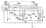
次に、漏洩電流低減装置の動作を、より詳細に説明する。まず、ノイズフィルタ9を、図2を用いて説明する。図2において、100a乃至100cは、ノイズフィルタ9の入力端子である。これらの入力端子100a乃至100cは、商用交流三相電源1の各相に接続されるものである。また、これらの入力端子100a乃至100cよりも出力側では、相間コンデンサ101a乃至101cが商用交流三相電源1の各相間に接続される。また、相間コンデンサ101a乃至101cよりも出力側の各相には、コモンモードコイル102a乃至102cが接続される。
Next, the operation of the leakage current reducing device will be described in more detail. First, the
そして、これらのコモンモードコイル102a乃至102cよりも出力側には、ノイズフィルタ9の出力端子103a乃至103cが設けられる。これらの出力端子103a乃至103cは、コンバータ3に接続されるものである。また、コモンモードコイル102a乃至102cと出力端子103a乃至103cの間には、接地コンデンサ104a乃至104cが接続される。これらの接地コンデンサ104a乃至104cは、アース端子105に接続される。このアース端子105は、ノイズフィルタ用接地線10に接続されるものである。
The
さらに、図3を用いて、ノイズフィルタ9の外部接続の電気的な等価回路を説明する。図3において、1a乃至1cは、それぞれ、商用交流三相電源1の相電圧である。電源用接地線2は、相電圧1cに接続される電力供給線と接続される。また、3a乃至3dは、等価電圧源である。等価電圧源3a乃至3cは、ノイズフィルタ9の出力端子103a乃至103cをコンバータ3に接続した場合に、ノイズフィルタ9の出力端子103a乃至103cに現れる電圧の差動成分を出力するものである。一方、等価電圧源4dは、同相成分を出力するものである。また、6aは浮遊容量である。この浮遊容量6aは、モータの巻線と接地されたモータの筐体間に発生するものである。
Further, an electrically equivalent circuit of the external connection of the
ここで、図4を用いて、変圧器11がない回路におけるノイズフィルタ9の負荷起因同相ノイズ除去効果について着目する。まず、等価電圧源3a乃至3cは差動電圧源であり、同相ノイズとは独立に扱うことができるため、ここでは無視する。また、ここでは負荷に起因する同相ノイズの影響のみを検討対象とするため、電源の相電圧に対応する1a乃至1cの電圧源も無視できる。これらの等価電圧源1a等を無視するため、それぞれを取り除いたうえで両端をショートする。また、商用交流三相電源1の各相に接続された相間コンデンサ101a乃至101cは、差動電圧に対しては有効に働く。しかし、これらのコンデンサ101a乃至101cは、同相電圧に対しては無効である。即ち、これらのコンデンサ101a乃至101cは、接続されていないものと扱うことができる。従って、コンバータ3から商用交流三相電源1に流出する同相ノイズの発生源は、同相成分を出力する等価電圧源3dとみなしてよい。
Here, with reference to FIG. 4, attention is focused on the load-induced common-mode noise removal effect of the
かかる場合、等価電圧源3d、接地コンデンサ104a乃至104c、ノイズフィルタ用接地線10、アース経路(図示せず)、電気機器用接地線7、浮遊容量6aを経由して等価電圧源3dに戻る回路ループ15が、ノイズの電流経路の一方となる。そして、等価電圧源3d、コモンモードコイル102a乃至102c、電源用接地線2、アース経路(図示せず)、電気機器用接地線7、浮遊容量6aを経由して等価電圧源3dに戻る回路ループ16が、ノイズの電流経路の他方となる。
In such a case, a circuit that returns to the
これらの回路ループ15、16に流れるノイズの電流分流比は、両回路ループ15、16のインピーダンス比で決定される。従って、ノイズが商用交流三相電源1へ流出することを効果的に低減するには、回路ループ15のインピーダンスを回路ループ16より比較して極力小さくすることが望まれる。即ち、接地コンデンサ104a乃至104cの容量を大きくして、回路ループ15のインピーダンスを小さくするか、コモンモードコイル102a乃至102cのインダクタンスを大きくし、回路ループ16のインピーダンスを大きくする必要がある。
The current shunt ratio of noise flowing in these
上述内容を踏まえ、商用交流三相電源1にノイズフィルタ9を接続した場合に流れる漏洩電流について、より詳細に検討する。まず、中性点基準のR相電圧、S相電圧、T相電圧を、それぞれ、VRN、VSN、VTNとする。各相の電圧の振幅をEa乃至Ecとすると、各相電圧は次式で表される。
VRN=Ea (1)
VSN=Eb・(−1/2−j31/2/2) (2)
VTN=Ec・(−1/2+j31/2/2) (3)
Based on the above description, the leakage current that flows when the
V RN = Ea (1)
V SN = Eb · (−1 / 2−j3 1/2 / 2) (2)
V TN = Ec · (−1 / 2 + j3 1/2 / 2) (3)
本実施の形態では、商用交流三相電源1のT相が接地される。従って、T相基準に変換されたR相電圧、S相電圧、T相電圧は、(1)式乃至(3)式より、次式で表される。ここで、VRT、VST、VTTは、それぞれ、T相基準に変換されたR相電圧、S相電圧、T相電圧である。
VRT=VRN−VTN=Ea−Ec・(−1/2+j31/2/2) (4)
VST=VSN−VTN
=Eb・(−1/2−j31/2/2)
−Ec・(−1/2+j31/2/2) (5)
VTT=0 (6)
In the present embodiment, the T phase of the commercial AC three-phase power source 1 is grounded. Therefore, the R-phase voltage, the S-phase voltage, and the T-phase voltage converted to the T-phase reference are expressed by the following equations from the equations (1) to (3). Here, V RT , V ST , and V TT are an R-phase voltage, an S-phase voltage, and a T-phase voltage converted to a T-phase reference, respectively.
V RT = V RN -V TN = Ea-Ec · (-1 / 2 + j3 1/2 / 2) (4)
V ST = V SN −V TN
= Eb · (−1 / 2−j3 1/2 / 2)
-Ec · (-1 / 2 + j3 1/2 / 2) (5)
V TT = 0 (6)
さらに、中性点を基準とした相電圧の振幅が互いに等しいEpとすると、次の関係が成り立つ。
Ea=Eb=Ec=Ep (7)
上記条件を考慮すると、(4)式乃至(6)式は、次式に変形できる。
VRT=Ep・(3/2−j31/2/2) (8)
VST=−Ep・j31/2 (9)
VTT=0 (10)
Furthermore, when the phase voltage amplitudes with respect to the neutral point are equal to Ep, the following relationship is established.
Ea = Eb = Ec = Ep (7)
In consideration of the above conditions, the equations (4) to (6) can be transformed into the following equations.
V RT = Ep · (3 / 2−j3 1/2 / 2) (8)
V ST = −Ep · j3 1/2 (9)
V TT = 0 (10)
さらに、接地コンデンサ104a乃至104cの容量をC104a乃至C104cとし、インピーダンスをZC104a乃至ZC104cとする。商用交流三相電源1の角周波数ωとすると、次の関係が成り立つ。
ZC104a=1/(jωC104a) (11)
ZC104b=1/(jωC104b) (12)
ZC104c=1/(jωC104c) (13)
Furthermore, the capacity of the
Z C104a = 1 / (jωC 104a ) (11)
Z C104b = 1 / (jωC 104b ) (12)
Z C104c = 1 / (jωC 104c ) (13)
ここで、商用交流電源の角周波数においては、コモンモードコイル102a乃至102cのインピーダンスはほぼ0として無視できる。即ち、接地コンデンサ104a乃至104cに流れる電流は、接地コンデンサ104a乃至104cのインピーダンスがほぼ決定している。そして、各コンデンサ104a乃至104cに流れる電流は、(8)式乃至(13)式から以下のように求めることができる。
IC104a=VRT/ZC104a
=jωC104aEp・(3/2−j31/2/2)
=ωC104a・Ep・31/2(1/2+j31/2/2) (14)
IC104b=VST/ZC104b
=−jωC104bEp・(j31/2)
=ωC104bEp31/2 (15)
IC104c=VTT/ZC104c・0=0 (16)
Here, at the angular frequency of the commercial AC power supply, the impedance of the
I C104a = V RT / Z C104a
= JωC 104a Ep · (3 / 2−j3 1/2 / 2)
= ΩC 104a · Ep · 3 1/2 ( 1/2 + j3 1/2 / 2) (14)
I C104b = V ST / Z C104b
= -JωC 104b Ep · (j3 1/2 )
= ΩC 104b Ep3 1/2 (15)
I C104c = V TT / Z C104c · 0 = 0 (16)
ここで、各接地コンデンサ104a乃至104cの容量を互いに等しいCとすると、次の関係が成り立つ。
C104a=C104b=C (17)
漏洩電流は、各接地コンデンサ104a乃至104cに流れる電流の和に等しい。従って、漏洩電流は、次式で表される。
IN=IC104a+IC104b+IC104c
=ωC104aEp・31/2(1/2+j31/2/2)
+ωC104bEp・31/2
=ωCEp・3(31/2/2+j1/2) (18)
即ち、漏洩電流は、接地コンデンサ104a乃至104cの容量に比例した値となる。即ち、変圧器11がない一般的なノイズフィルタ9の同相ノイズ低減効果を向上させるために接地コンデンサ104a乃至104cの容量を拡大した場合には、同時に漏洩電流が増加し、漏洩遮断器が誤動作する要因となってしまうため、無闇に接地コンデンサ104a乃至104cの容量を拡大することができない。
Here, if the capacitances of the
C 104a = C 104b = C (17)
The leakage current is equal to the sum of the currents flowing through the
I N = I C104a + I C104b + I C104c
= ΩC 104a Ep · 3 1/2 ( 1/2 + j3 1/2 / 2)
+ ΩC 104b Ep · 3 1/2
= ΩCEp · 3 (3 1/2 / 2 + j1 / 2) (18)
That is, the leakage current has a value proportional to the capacitance of the
最後に、変圧器11及び抵抗14を考慮する。まず、抵抗14の抵抗値をR、抵抗14を流れる補償電流値をIR、変圧器11の巻線比をKとする。このとき、補償電流値とRS相間電圧の間には、次の関係が成り立つ。
IR=K・VRS/R
={K・Ep・31/2(31/2/2+j1/2)}/R (19)
Finally, consider
I R = K · V RS / R
= {K · Ep · 3 1/2 (3 1/2 / 2 + j1 / 2)} / R (19)
ここで、変圧器11等により、漏洩電流をなくすためには、(18)式の漏洩電流と(19)式の電流が等しくなればよい。そして、このときの関係は、次式で表される。
31/2ωC=K/R (20)
即ち、(20)式を満たすように、変圧器11の巻線比及び抵抗値を決定すれば、漏洩電流が流れない。
Here, in order to eliminate the leakage current by the
3 1/2 ωC = K / R (20)
That is, if the winding ratio and resistance value of the
なお、抵抗14で発生する損失PRは、次式で表される。
PR=R・|IR|2=3・K2・Ep2/R
=3・31/2・ωC・K・Ep2 (21)
(21)式より、抵抗14で発生する損失は、変圧器11の巻線比に比例することがわかる。
Incidentally, the loss P R generated by the
P R = R · | I R | 2 = 3 · K 2 · Ep 2 / R
= 3 ・ 3 1/2・ ωC ・ K ・ Ep 2 (21)
From the equation (21), it can be seen that the loss generated in the
以上で説明した実施の形態によれば、簡素な構成で接地コンデンサ104a乃至104cを流れる漏洩電流による遮断漏洩機の誤動作を防止できる。さらに、(20)式を満たすように巻線比、抵抗14を選択すれば、接地コンデンサ104a乃至104cの容量を大きくしても漏洩電流を打ち消すことができる。これにより、ノイズフィルタ9によるノイズ減衰量を大きくすることが可能となる。
According to the embodiment described above, it is possible to prevent malfunction of the circuit breaker due to the leakage current flowing through the
また、接地コンデンサ104a乃至104cの大容量化は、大型コモンモードコイル102a乃至102cの使用を要しない。このため、ノイズフィルタ9の小型化、ローコスト化が可能となる。加えて、抵抗14で発生する損失は、変圧器11の巻線比に比例する。従って、二次巻線13に印加される電圧が、一次巻線に印加される電圧よりも小さくなるように巻数を設定すれば、抵抗14で発生する損失を小さくすることができる。
Further, increasing the capacity of the
実施の形態2.
図5はこの発明の実施の形態2における漏洩電流低減装置の回路構成図である。なお、実施の形態1と同一又は相当部分には同一符号を付して説明を省略する。
FIG. 5 is a circuit configuration diagram of a leakage current reducing apparatus according to
実施の形態1における(20)式より、接地コンデンサ104a乃至104cに流れる漏洩電流の大きさは、商用交流三相電源1の周波数の影響を受ける。従って、商用交流三相電源1の周波数が異なる複数の地区に対応するためには、それぞれの地区に最適な素子を複数持つことが必要となる。そこで、実施の形態2では、それぞれの地区に最適化された漏洩電流低減装置を一種類に統一する構成とした。以下、実施の形態2における漏洩電流低減装置を説明する。
From the equation (20) in the first embodiment, the magnitude of the leakage current flowing through the grounding
実施の形態2における変圧器の17の二次巻線18は、実施の形態1と同様に、正極側端からなる一端がT相に接続されている。さらに、実施の形態2における二次巻線18には、中間引き出し線19が設けられる。この中間引き出し線19の端部には、引き出し端子20が設けられる。これにより、二次巻線18は、実質的な巻数を変化させる。ユーザは、適宜、当該地区に供給される商用交流三相電源1の周波数に応じて、抵抗14の一端を二次巻線18の負極側端18aからなる他端及び引き出し端子20のいずれか一方に接続させる。
As in the first embodiment, the secondary winding 18 of the
以上で説明した実施の形態2によれば、地区共通の漏洩電流低減装置で漏洩電流を適切に低減できる。 According to the second embodiment described above, the leakage current can be appropriately reduced by the common leakage current reducing device in the district.
実施の形態3.
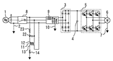
図6はこの発明の実施の形態3における漏洩電流低減装置の回路構成図である。なお、実施の形態1と同一又は相当部分には同一符号を付して説明を省略する。
FIG. 6 is a circuit configuration diagram of a leakage current reducing apparatus according to
実施の形態1及び2では、商用交流三相電源1のRS相間に差動ノイズが発生した場合に、高周波ノイズ電流がアースに流れることがある。そこで、実施の形態3では、当該ノイズがアースに流れることを防止する構成とした。より具体的には、実施の形態3は、実施の形態1における抵抗14とアースの間に、インダクタ21を直列接続した。
In the first and second embodiments, when differential noise occurs between the RS phases of the commercial AC three-phase power source 1, a high-frequency noise current may flow to the ground. Therefore, in the third embodiment, the noise is prevented from flowing to the ground. More specifically, in the third embodiment, the
以上で説明した実施の形態3によれば、商用交流三相電源1のRS相間に差動ノイズが発生しても、インダクタ21の高周波域でのインピーダンス上昇により、漏洩電流低減装置経由でアースに流れる高周波ノイズ電流を効果的に低減できる。なお、実施の形態1及び2においては、補正電流のレベルを決定するインピーダンス要素として抵抗14を利用しているため、コンデンサを利用している、例えば、先行技術文献1の第1の実施例と比較して高周波域のインピーダンスが高く、ノイズフィルタ9の大きな特性劣化には繋がらないのはいうまでもない。
According to the third embodiment described above, even if differential noise occurs between the RS phases of the commercial AC three-phase power supply 1, due to an increase in impedance in the high frequency region of the
実施の形態4.
図7はこの発明の実施の形態4における漏洩電流低減装置の回路構成図である。なお、実施の形態1と同一又は相当部分には同一符号を付して説明を省略する。
FIG. 7 is a circuit configuration diagram of a leakage current reducing apparatus according to
実施の形態1及び2では、商用交流三相電源1のRS相間に差動ノイズが発生した場合に、高周波ノイズ電流がアースに流れることがある。そこで、実施の形態3では、インダクタ21を直列接続した。一方、実施の形態4では、変圧器11の一次巻線12にローパスフィルタが設けられる。より具体的には、一次巻線12と並列にコンデンサ22が接続される。そして、コンデンサ22の一次巻線12正極側と商用交流三相電源1の間に抵抗23が接続される。
In the first and second embodiments, when differential noise occurs between the RS phases of the commercial AC three-phase power source 1, a high-frequency noise current may flow to the ground. Therefore, in the third embodiment, the
以上で説明した実施の形態4によれば、実施の形態3と同様の効果が得られる。 According to the fourth embodiment described above, the same effect as in the third embodiment can be obtained.
1 商用交流三相電源
1a〜1c 相電圧
2 電源用接地線
3 コンバータ
3a〜3d 等価電圧源
4 コンデンサ
5 インバータ
6 電気機器
6a 浮遊容量
7 機器用接地線
8 漏電遮断器
9 ノイズフィルタ
10 ノイズフィルタ用接地線
11 変圧器
12 一次巻線
13 二次巻線
14 抵抗
15、16 回路ループ
17 変圧器
18 二次巻線
18a 負極側端
19 中間引き出し線
20 引き出し端子
21 インダクタ
22 コンデンサ
23 抵抗
100a〜100c 入力端子
101a〜101c 相間コンデンサ
102a〜102c コモンモードコイル
103a〜103c 出力端子
104a〜104c 接地コンデンサ
105 アース端子
DESCRIPTION OF SYMBOLS 1 Commercial AC three-phase power source 1a-
Claims (5)
前記交流三相電源により駆動される機器と、
前記交流三相電源及び前記機器の間に接続された漏電遮断器と、
前記漏電遮断器及び前記機器の間に設けられ、前記交流三相電源の各相とアースの間にコンデンサを接続して、前記機器側から前記交流三相電源側へのノイズの流出を防止するノイズフィルタと、
を有するシステムにおいて前記コンデンサを経由してアースに流れる漏洩電流を低減させる漏洩電流低減装置であって、
前記交流三相電源の二つの非接地線の間に接続された変圧器の一次巻線と、
一端が前記交流三相電源の接地相に接続された前記変圧器の二次巻線と、
一端が前記二次巻線の他端に接続されるとともに、他端がアースに接続され、前記漏洩電流と反体位相でかつ振幅の等しい電流を前記交流三相電源の接地相とアースの間に供給する抵抗と、
を備えたことを特徴とする漏洩電流低減装置。 AC three-phase power supply with any one phase grounded,
A device driven by the AC three-phase power source;
An earth leakage circuit breaker connected between the AC three-phase power source and the device;
Provided between the earth leakage circuit breaker and the device, a capacitor is connected between each phase of the AC three-phase power source and the ground to prevent noise from flowing out from the device side to the AC three-phase power source side. A noise filter,
A leakage current reducing device for reducing leakage current flowing to the ground via the capacitor in a system comprising:
A primary winding of a transformer connected between two ungrounded wires of the AC three-phase power source;
A secondary winding of the transformer, one end of which is connected to a ground phase of the AC three-phase power source;
One end is connected to the other end of the secondary winding, and the other end is connected to the ground, and a current having the opposite phase and the same amplitude as the leakage current is connected between the ground phase of the AC three-phase power source and the ground. Resistance to supply to,
A leakage current reducing device comprising:
抵抗は、前記交流三相電源の周波数に応じて、前記二次巻線の他端及び前記引き出し端子のいずれか一方に一端を接続されたことを特徴とする請求項1又は請求項2に記載の漏洩電流低減装置。 The secondary winding includes one end connected to the ground phase of the AC three-phase power source and the other end connected to one end of the resistor, and a lead terminal for changing the number of turns,
3. The resistor according to claim 1, wherein one end of the resistor is connected to one of the other end of the secondary winding and the lead terminal according to a frequency of the AC three-phase power source. Leakage current reduction device.
Priority Applications (1)
| Application Number | Priority Date | Filing Date | Title |
|---|---|---|---|
| JP2007321289A JP2009148045A (en) | 2007-12-12 | 2007-12-12 | Leak current reducing device |
Applications Claiming Priority (1)
| Application Number | Priority Date | Filing Date | Title |
|---|---|---|---|
| JP2007321289A JP2009148045A (en) | 2007-12-12 | 2007-12-12 | Leak current reducing device |
Publications (1)
| Publication Number | Publication Date |
|---|---|
| JP2009148045A true JP2009148045A (en) | 2009-07-02 |
Family
ID=40918029
Family Applications (1)
| Application Number | Title | Priority Date | Filing Date |
|---|---|---|---|
| JP2007321289A Pending JP2009148045A (en) | 2007-12-12 | 2007-12-12 | Leak current reducing device |
Country Status (1)
| Country | Link |
|---|---|
| JP (1) | JP2009148045A (en) |
Cited By (3)
| Publication number | Priority date | Publication date | Assignee | Title |
|---|---|---|---|---|
| WO2021040197A1 (en) * | 2019-08-29 | 2021-03-04 | 효성중공업 주식회사 | Independent microgrid system and inverter device |
| JP2021129263A (en) * | 2020-02-17 | 2021-09-02 | フジテック株式会社 | Noise elimination device |
| EP3989421A4 (en) * | 2019-06-18 | 2022-06-22 | Mitsubishi Electric Corporation | Leakage current reduction device |
-
2007
- 2007-12-12 JP JP2007321289A patent/JP2009148045A/en active Pending
Cited By (5)
| Publication number | Priority date | Publication date | Assignee | Title |
|---|---|---|---|---|
| EP3989421A4 (en) * | 2019-06-18 | 2022-06-22 | Mitsubishi Electric Corporation | Leakage current reduction device |
| WO2021040197A1 (en) * | 2019-08-29 | 2021-03-04 | 효성중공업 주식회사 | Independent microgrid system and inverter device |
| KR20210026165A (en) * | 2019-08-29 | 2021-03-10 | 효성중공업 주식회사 | Independent microgrid system and inverter device |
| KR102274048B1 (en) * | 2019-08-29 | 2021-07-08 | 효성중공업 주식회사 | Independent microgrid system and inverter device |
| JP2021129263A (en) * | 2020-02-17 | 2021-09-02 | フジテック株式会社 | Noise elimination device |
Similar Documents
| Publication | Publication Date | Title |
|---|---|---|
| US9281738B2 (en) | Power conversion apparatus with low common mode noise and application systems thereof | |
| KR100403541B1 (en) | Active Common Mode EMI Filter for Eliminating Conducted Electromagnetic Interference | |
| JP5263663B2 (en) | Conductive noise filter | |
| RU2478978C2 (en) | Transformer check device | |
| JP6568743B2 (en) | Conductive noise suppression circuit and inverter device | |
| JPH1094244A (en) | Active common-mode canceler | |
| JP5022236B2 (en) | Active electromagnetic compatibility filter for machine tools | |
| US9013840B2 (en) | Adaptive line filter | |
| JP4351916B2 (en) | Noise filter | |
| JP2012044812A (en) | Noise filter and emc filter using the same | |
| EP3229363A1 (en) | Power converter | |
| JP2008530964A5 (en) | ||
| JP4106496B2 (en) | Inverter common mode voltage / current suppression method and apparatus | |
| TW201843914A (en) | Power conversion device and power conversion system | |
| JP2009148045A (en) | Leak current reducing device | |
| US10090753B1 (en) | Power conversion device and power conversion system | |
| JP2009142076A (en) | Low noise power conversion apparatus | |
| JP6239468B2 (en) | Medical equipment | |
| JPH11266530A (en) | Leakage current reducing equipment for electrical apparatus | |
| JPH11299264A (en) | Method and apparatus for suppressing common mode voltage of inverter | |
| US11355945B2 (en) | Compensation device for discharge currents | |
| US11437970B2 (en) | Method and apparatus for common-mode voltage cancellation | |
| JP2006271026A (en) | Leakage current suppression circuit | |
| RU2402130C1 (en) | Device for protection against ground short circuit in networks with compensation of capacitance circuit | |
| JP7012185B1 (en) | Voltage detection circuit |