JP2009144665A - Turbo supercharger and supercharging engine system - Google Patents
Turbo supercharger and supercharging engine system Download PDFInfo
- Publication number
- JP2009144665A JP2009144665A JP2007325206A JP2007325206A JP2009144665A JP 2009144665 A JP2009144665 A JP 2009144665A JP 2007325206 A JP2007325206 A JP 2007325206A JP 2007325206 A JP2007325206 A JP 2007325206A JP 2009144665 A JP2009144665 A JP 2009144665A
- Authority
- JP
- Japan
- Prior art keywords
- communication
- scroll
- nozzle
- engine
- control valve
- Prior art date
- Legal status (The legal status is an assumption and is not a legal conclusion. Google has not performed a legal analysis and makes no representation as to the accuracy of the status listed.)
- Pending
Links
Images


Classifications
-
- Y—GENERAL TAGGING OF NEW TECHNOLOGICAL DEVELOPMENTS; GENERAL TAGGING OF CROSS-SECTIONAL TECHNOLOGIES SPANNING OVER SEVERAL SECTIONS OF THE IPC; TECHNICAL SUBJECTS COVERED BY FORMER USPC CROSS-REFERENCE ART COLLECTIONS [XRACs] AND DIGESTS
- Y02—TECHNOLOGIES OR APPLICATIONS FOR MITIGATION OR ADAPTATION AGAINST CLIMATE CHANGE
- Y02T—CLIMATE CHANGE MITIGATION TECHNOLOGIES RELATED TO TRANSPORTATION
- Y02T10/00—Road transport of goods or passengers
- Y02T10/10—Internal combustion engine [ICE] based vehicles
- Y02T10/12—Improving ICE efficiencies
Abstract
Description
本発明は、複数の気筒を有するエンジンの排気エネルギーを利用してエンジンへの吸気を加圧するターボ過給機、及び過給エンジンシステムに関する。 The present invention relates to a turbocharger that pressurizes intake air into an engine by using exhaust energy of an engine having a plurality of cylinders, and a supercharged engine system.
エンジンへの吸気を加圧する過給装置として、ターボチャージャー(ターボ過給機)が用いられている。ターボチャージャーは、エンジンの排気エネルギーを利用してタービンホイールに回転動力を発生させ、タービンホイールの回転動力を利用してコンプレッサホイールを回転駆動することで、エンジンへの吸気を加圧する。 A turbocharger (turbocharger) is used as a supercharging device that pressurizes intake air into the engine. The turbocharger uses the exhaust energy of the engine to generate rotational power in the turbine wheel, and rotates the compressor wheel using the rotational power of the turbine wheel to pressurize the intake air to the engine.
ターボチャージャーは、エンジン回転数が低いときには、タービンへ供給される排出ガス流量が少なくなるため、過給圧が上昇しにくくなる。そこで、エンジン回転数が低いときに過給圧を速やかに高めるために、タービンのスクロール流路とタービンホイールとの間のノズルに可動ベーンが設けられた可変ノズル式ターボチャージャーが提案されている(例えば非特許文献1)。この可変ノズル式ターボチャージャーにおいて、エンジン回転数が低く、タービンへ供給される排出ガス流量が少ないときには、可動ベーン間の流路面積を小さくすることで、ノズルからタービンホイールの翼間流路に流入する排出ガスの流速を増大させて過給圧を高める。一方、エンジン回転数が高く、タービンへ供給される排出ガス流量が多いときには、可動ベーン間の流路面積を大きくすることで、大流量の排出ガスがノズルからタービンホイールの翼間流路へ流れるように制御している。 In the turbocharger, when the engine speed is low, the flow rate of exhaust gas supplied to the turbine decreases, so that the supercharging pressure does not easily increase. Therefore, in order to quickly increase the supercharging pressure when the engine speed is low, a variable nozzle turbocharger in which a movable vane is provided in the nozzle between the scroll path of the turbine and the turbine wheel has been proposed ( For example, Non-Patent Document 1). In this variable nozzle turbocharger, when the engine speed is low and the flow rate of exhaust gas supplied to the turbine is small, the flow area between the movable vanes is reduced to flow into the flow path between the blades of the turbine wheel. Increase the supercharging pressure by increasing the flow rate of exhaust gas. On the other hand, when the engine speed is high and the flow rate of exhaust gas supplied to the turbine is large, the flow area between the movable vanes is increased so that a large flow rate of exhaust gas flows from the nozzle to the flow path between the blades of the turbine wheel. So that it is controlled.
また、燃焼後の排出ガスは排気弁が開いているときにエンジンの気筒内から排気通路へ排出されるため、排気通路へ排出された排出ガスには、排気弁の開閉に伴って脈動(パルス流)が生じる。そして、エンジンが複数の気筒を有する多気筒エンジンである場合は、吸気行程−圧縮行程−膨張行程−排気行程のサイクルが各気筒毎にずれているため、各気筒からの排出ガスに生じる脈動の位相は互いに異なる。そのため、各気筒からの排出ガスを共通の排気通路で合流させてからタービンへ供給する場合は、各気筒からの排出ガスが互いに干渉してその脈動が減衰することで、タービンへ供給される排気エネルギーが減少する。その結果、特にエンジン回転数が低い(タービンへ供給される排出ガス流量が少ない)ときに、過給圧が上昇しにくくなる。そこで、各気筒間の排気干渉による排気エネルギーの減少を抑えるために、タービンのスクロール流路が2分割されたツインスクロール式ターボチャージャーも提案されている(例えば特許文献1や非特許文献1)。このツインスクロール式ターボチャージャーにおいては、一部の気筒からの排出ガスを2分割されたスクロール流路の一方へ供給し、残りの気筒からの排出ガスを2分割されたスクロール流路の他方へ供給することで、各気筒間の排気干渉による影響を少なくしている。 Further, since the exhaust gas after combustion is exhausted from the engine cylinder to the exhaust passage when the exhaust valve is open, the exhaust gas exhausted to the exhaust passage is pulsated (pulsed) as the exhaust valve opens and closes. Flow). When the engine is a multi-cylinder engine having a plurality of cylinders, the cycle of the intake stroke-compression stroke-expansion stroke-exhaust stroke is shifted for each cylinder. The phases are different from each other. For this reason, when exhaust gases from the cylinders are combined in a common exhaust passage and then supplied to the turbine, the exhaust gases supplied from the cylinders interfere with each other and the pulsation attenuates, whereby the exhaust gas supplied to the turbine. Energy is reduced. As a result, particularly when the engine speed is low (the exhaust gas flow rate supplied to the turbine is small), the supercharging pressure is unlikely to increase. Therefore, in order to suppress a decrease in exhaust energy due to exhaust interference between the cylinders, a twin scroll turbocharger in which the scroll flow path of the turbine is divided into two has been proposed (for example, Patent Document 1 and Non-Patent Document 1). In this twin scroll turbocharger, exhaust gas from some cylinders is supplied to one of the two divided scroll flow paths, and exhaust gas from the remaining cylinders is supplied to the other of the two divided scroll flow paths. By doing so, the influence of the exhaust interference between the cylinders is reduced.
可変ノズル式ターボチャージャーにおいては、各気筒からの排出ガスを共通の排気通路で合流させてからタービンへ供給するため、各気筒からの排出ガスが互いに干渉してその脈動が減衰することで、タービンへ供給される排気エネルギーが減少する。そのため、各気筒からの排出ガスの脈動が減衰した分、過給圧が低下する。 In the variable nozzle type turbocharger, exhaust gases from the cylinders are combined in a common exhaust passage and then supplied to the turbine. Therefore, the exhaust gases from the cylinders interfere with each other and the pulsation is attenuated. Exhaust energy supplied to is reduced. For this reason, the boost pressure is reduced by the amount of pulsation of exhaust gas from each cylinder being attenuated.
また、ツインスクロール式ターボチャージャーにおいて、各気筒間の排気干渉による影響を少なくすることは、エンジン回転数が低いときの過給圧を高める点では有効であるが、エンジン回転数が高く、タービンへ供給される排出ガス流量が多いときには、エンジン背圧(タービン入口圧力)が増大しやすくなる。タービン入口圧力が高くなると、エンジンの気筒内から燃焼後の排出ガスが排出されにくくなり、エンジンのポンピングロスが増大する。 In a twin scroll turbocharger, reducing the influence of exhaust interference between cylinders is effective in increasing the supercharging pressure when the engine speed is low, but the engine speed is high and When the exhaust gas flow rate to be supplied is large, the engine back pressure (turbine inlet pressure) tends to increase. When the turbine inlet pressure becomes high, the exhaust gas after combustion becomes difficult to be discharged from the cylinder of the engine, and the pumping loss of the engine increases.
本発明は、過給圧の低下を抑制することができるとともにタービン入口圧力の増大を抑制することができるターボ過給機及び過給エンジンシステムを提供することを目的とする。 An object of the present invention is to provide a turbocharger and a supercharged engine system capable of suppressing a decrease in supercharging pressure and suppressing an increase in turbine inlet pressure.
本発明に係るターボ過給機及び過給エンジンシステムは、上述した目的を達成するために以下の手段を採った。 The turbocharger and the supercharged engine system according to the present invention employ the following means in order to achieve the above-described object.
本発明に係るターボ過給機は、複数の気筒からの排出ガスに生じる脈動の位相が互いに異なるエンジンの排気エネルギーを利用してエンジンへの吸気を加圧するターボ過給機であって、エンジンの各気筒毎に設けられた複数のスクロール流路であって、その各々に各気筒からの排出ガスがそれぞれ流入する複数のスクロール流路と、複数のスクロール流路からの排出ガスが流入するノズルと、ノズルを通って供給される排出ガスのエネルギーを利用して回転駆動するタービンホイールと、タービンホイールの回転動力を利用してエンジンへの吸気を加圧するコンプレッサと、ノズルより上流側で複数のスクロール流路同士を互いに連通させる連通状態と、ノズルより上流側での複数のスクロール流路同士の連通を遮断する遮断状態と、に選択的に切り替わることが可能な連通制御弁と、を有し、連通制御弁が連通状態にある場合には、各気筒から各スクロール流路にそれぞれ流入した排出ガスは、互いに干渉してノズルに供給され、連通制御弁が遮断状態にある場合には、各気筒から各スクロール流路にそれぞれ流入した排出ガスは、互いに干渉することなくノズルに供給されることを要旨とする。 A turbocharger according to the present invention is a turbocharger that pressurizes intake air into an engine by using exhaust energy of engines having pulsation phases different from each other in exhaust gases from a plurality of cylinders. A plurality of scroll channels provided for each cylinder, each of which has a plurality of scroll channels into which exhaust gas from each cylinder flows, and a nozzle into which exhaust gas from the plurality of scroll channels flows. A turbine wheel that rotates using the energy of exhaust gas supplied through the nozzle, a compressor that pressurizes intake air to the engine using the rotational power of the turbine wheel, and a plurality of scrolls upstream of the nozzle Select between a communication state in which the flow paths communicate with each other and a blocking state in which communication between the plurality of scroll flow paths on the upstream side of the nozzle is blocked When the communication control valve is in a communication state, the exhaust gas flowing into each scroll flow path from each cylinder interferes with each other and is supplied to the nozzle. When the communication control valve is in the shut-off state, the gist is that the exhaust gas flowing into each scroll flow path from each cylinder is supplied to the nozzle without interfering with each other.
本発明の一態様では、ノズルより上流側で複数のスクロール流路同士を互いに連通させるための連通室をさらに有し、連通制御弁は、ノズルより上流側で複数のスクロール流路と連通室とを連通させる連通状態と、ノズルより上流側での複数のスクロール流路と連通室との連通を遮断する遮断状態と、に選択的に切り替わることが可能であることが好適である。 In one aspect of the present invention, the apparatus further includes a communication chamber for communicating the plurality of scroll flow paths with each other upstream from the nozzle, and the communication control valve includes a plurality of scroll flow paths and communication chambers upstream from the nozzle. It is preferable that it is possible to selectively switch between a communication state in which communication is established and a blocking state in which communication between the plurality of scroll flow paths and the communication chamber on the upstream side of the nozzle is blocked.
本発明の一態様では、連通制御弁は、エンジン回転数に応じて連通状態と遮断状態のいずれかに選択的に切り替わるものであり、連通制御弁が連通状態にある場合のエンジン回転数が、連通制御弁が遮断状態にある場合のエンジン回転数よりも高いことが好適である。 In one aspect of the present invention, the communication control valve is selectively switched between a communication state and a shut-off state according to the engine speed, and the engine speed when the communication control valve is in the communication state is It is preferable that the engine speed be higher than that when the communication control valve is in the shut-off state.
また、本発明に係る過給エンジンシステムは、複数の気筒からの排出ガスに生じる脈動の位相が互いに異なるエンジンと、エンジンの排気エネルギーを利用してエンジンへの吸気を加圧するターボ過給機と、を備える過給エンジンシステムであって、前記ターボ過給機が、本発明に係るターボ過給機であることを要旨とする。 A supercharged engine system according to the present invention includes an engine having different pulsation phases generated in exhaust gases from a plurality of cylinders, and a turbocharger that pressurizes intake air into the engine using engine exhaust energy. The turbocharger is a turbocharger according to the present invention.
本発明において、連通制御弁が遮断状態にある場合には、各気筒から各スクロール流路にそれぞれ流入した排出ガスは、互いに干渉せずその脈動がほとんど減衰することなくノズルに供給されることで、各気筒間の排気干渉による排気エネルギーの減少を抑えることができるので、過給圧の低下を抑制することができる。また、連通制御弁が連通状態にある場合には、各気筒から各スクロール流路にそれぞれ流入した排出ガスは、互いに干渉してノズルに供給されることで、排出ガスの脈動が減衰するとともに、スクロール流路を流れる排出ガスの流路面積が気筒数倍になって流路抵抗が減少するため、タービン入口圧力の増大を抑制することができる。したがって、本発明によれば、過給圧の低下を抑制することができるとともに、タービン入口圧力の増大を抑制することができる。 In the present invention, when the communication control valve is in the shut-off state, the exhaust gas flowing into each scroll flow path from each cylinder is supplied to the nozzle without interfering with each other and with almost no attenuation of the pulsation. Since a decrease in exhaust energy due to exhaust interference between the cylinders can be suppressed, a decrease in supercharging pressure can be suppressed. In addition, when the communication control valve is in a communication state, exhaust gas that has flowed into each scroll channel from each cylinder interferes with each other and is supplied to the nozzle, whereby the pulsation of the exhaust gas is attenuated, Since the flow passage area of the exhaust gas flowing through the scroll flow passage is multiplied by the number of cylinders and the flow passage resistance is reduced, an increase in turbine inlet pressure can be suppressed. Therefore, according to the present invention, a decrease in supercharging pressure can be suppressed, and an increase in turbine inlet pressure can be suppressed.
以下、本発明を実施するための形態(以下実施形態という)を図面に従って説明する。 DESCRIPTION OF EMBODIMENTS Hereinafter, embodiments for carrying out the present invention (hereinafter referred to as embodiments) will be described with reference to the drawings.
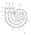
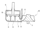
図1〜3は、本発明の実施形態に係るターボ過給機12を備える過給エンジンシステムの概略構成を示す図であり、図1は過給エンジンシステムの全体構成の概略を示し、図2はタービンホイール24の軸線方向と垂直方向から見たターボ過給機12のタービン20の内部構成を示し、図3はタービンホイール24の軸線方向と平行方向から見たターボ過給機12のタービン20の内部構成を示す。本実施形態に係るターボ過給機(ターボチャージャー)12は、内燃機関10の排気エネルギーを利用して内燃機関10への吸気を加圧するものであり、内燃機関10の排気エネルギーを利用してタービンホイール24に回転動力を発生させるタービン20と、タービンホイール24の回転動力を利用して内燃機関10への吸気を加圧するコンプレッサ18と、を備える。
1-3 is a figure which shows schematic structure of a supercharged engine system provided with the
内燃機関10は、複数の気筒を有する多気筒エンジンである。図1は、内燃機関10が3つの気筒1〜3を有する直列3気筒エンジンである例を示している。各気筒1〜3においては、排気弁が開いているときに、燃焼後の排出ガスが各気筒1〜3に対応して設けられた排気通路31〜33へそれぞれ排出される。各排気通路31〜33に排出された排出ガスには、排気弁の開閉に伴って脈動(パルス流)が生じる。そして、内燃機関10においては、吸気行程−圧縮行程−膨張行程−排気行程のサイクルが各気筒毎にずれている。そのため、内燃機関10の各気筒からの排出ガスに生じる脈動の位相は互いに異なる。例えば直列3気筒の4行程サイクル機関の場合は、各気筒1〜3において、吸気行程−圧縮行程−膨張行程−排気行程のサイクルがクランク角度で240°ずつずれており、図5に示すように、各気筒1〜3から各排気通路31〜33へそれぞれ排出される排出ガスの圧力波に生じる脈動(パルス流)の位相は、クランク角度でほぼ240°ずつずれている。
The
ターボ過給機12のタービン20は、内燃機関10の各気筒からの排出ガスが流入する渦巻形状のスクロール流路21〜23と、スクロール流路21〜23からの排出ガスが流入するノズル26と、ノズル26を通って供給される排出ガスのエネルギーを利用して回転駆動することで回転動力を発生するタービンホイール24と、を有する。ノズル26は、タービンホイール24よりもその半径方向外側に位置し、スクロール流路21〜23は、ノズル26よりもタービンホイール半径方向外側に位置する。コンプレッサ18のコンプレッサホイール19は、シャフト(回転軸)17を介してタービンホイール24に連結されており、タービンホイール24とともにコンプレッサホイール19が回転駆動することで、内燃機関10への吸気が圧縮される。コンプレッサ18で加圧された吸気は、インタークーラー13で冷却されてから、吸気弁が開いているときに各気筒1〜3内へ供給される。
A
本実施形態では、タービン20のスクロール流路が内燃機関10の各気筒毎に対応して気筒数と同数設けられており、各スクロール流路には各気筒からの排出ガスがそれぞれ流入する。内燃機関10が3気筒エンジンである例では、互いに分割された3つのスクロール流路21〜23が各気筒1〜3毎に対応して設けられている。スクロール流路21は排気通路31に連通していることで、気筒1からの排出ガスがスクロール流路21に流入する。そして、スクロール流路22は排気通路32に連通していることで、気筒2からの排出ガスがスクロール流路22に流入し、スクロール流路23は排気通路33に連通していることで、気筒3からの排出ガスがスクロール流路23に流入する。前述のように、各気筒1〜3からの排出ガスに生じる脈動(パルス流)の位相は互いに異なるため、各スクロール流路21〜23に流入する排出ガスに生じる脈動の位相も互いに異なる。図2,3に示す例では、タービン20のスクロール流路がタービンホイール24の半径方向に関して3つのスクロール流路21〜23に分割されている。各スクロール流路21〜23内の排出ガスは、ノズル26を通ってタービンホイール24の翼間流路に供給される。その際には、ノズル26で排出ガスの圧力が速度に変換されることにより、タービンホイール24の翼間流路に供給される排出ガスの流速が増大する。ノズル26においては、主にスクロール流路21からの排出ガスが流入する流路26−1と、主にスクロール流路22からの排出ガスが流入する流路26−2と、主にスクロール流路23からの排出ガスが流入する流路26−3とが、タービンホイール24の周方向に沿って並んで形成されている。
In the present embodiment, the scroll flow path of the
さらに、本実施形態では、タービン20には、ノズル26より上流側で複数のスクロール流路21〜23同士を互いに連通させるための連通室25が設けられている。ここでの「上流側」は、排出ガス流れ方向に関しての上流側を表す。図2,3に示す例では、連通室25は、スクロール流路21〜23よりもシャフト17の軸線方向へ張り出して形成されており、各スクロール流路21〜23に開口している。そして、連通室25内には、ノズル26より上流側での複数のスクロール流路21〜23同士の連通状態を制御するための連通制御バルブ28が設けられている。図3に示す例では、連通室25及び連通制御バルブ28がスクロール流路21〜23の入口付近に配置されている。連通制御バルブ28は、ノズル26より上流側で複数のスクロール流路21〜23と連通室25とを連通させる連通状態(図2に示す開状態)と、ノズル26より上流側での複数のスクロール流路21〜23と連通室25との連通を遮断する遮断状態(図4に示す閉状態)と、に選択的に切り替わることが可能である。図2,3に示す例では、連通制御バルブ28は、シャフト17の軸線方向に沿って駆動可能であり、連通制御バルブ28をスクロール流路21〜23側へ駆動することで、連通室25の各スクロール流路21〜23への開口部が閉じられて遮断状態に切り替わる。一方、連通制御バルブ28をスクロール流路21〜23と反対側へ駆動することで、連通室25の各スクロール流路21〜23への開口部が開いて連通状態に切り替わる。連通制御バルブ28が連通状態にある場合は、図2に示すように、ノズル26より上流側で複数のスクロール流路21〜23同士が連通室25を介して互いに連通する。一方、連通制御バルブ28が遮断状態にある場合は、図4に示すように、ノズル26より上流側での複数のスクロール流路21〜23同士の連通が遮断される。ここでの連通制御バルブ28については、例えば図示しないアクチュエータにより駆動することができる。そして、連通制御バルブ28の駆動制御については、例えば電子制御ユニットから出力される制御指令により行うことができる。
Furthermore, in the present embodiment, the
次に、本実施形態に係るターボ過給機12の動作について説明する。
Next, the operation of the
内燃機関10の低速運転時には、電子制御ユニットは、連通制御バルブ28を閉じることで遮断状態に制御する。つまり、図4に示すように、ノズル26より上流側での複数のスクロール流路21〜23と連通室25との連通を遮断することで、ノズル26より上流側での複数のスクロール流路21〜23同士の連通を遮断する。これによって、各気筒1〜3から各スクロール流路21〜23にそれぞれ流入した排出ガスは、その圧力波が互いに干渉することなくノズル26に供給される。そのため、各スクロール流路21〜23に流入した各気筒1〜3からの排出ガスは、その脈動(パルス流)のレベルがほとんど減衰することなくタービンホイール24の翼間流路へ供給される。これによって、各気筒1〜3間の排気干渉により排出ガスの圧力波の脈動が減衰することで生じる排気エネルギー損失を少なくすることができ、タービンホイール24の翼間流路へ供給される排気エネルギーの減少を抑えることができる。したがって、内燃機関10の低速運転時にタービン20へ供給される排出ガス流量が少なくても、高い排気エネルギーでタービンホイール24を効率よく回転駆動することができる。その結果、内燃機関10の低速運転時に、過給圧を高めることができ、内燃機関10のトルクを増大させることができる。
When the
さらに、各気筒1〜3からの排出ガスが互いに干渉せずその脈動がほとんど減衰しないことで、図5に示すように、排気弁が開いた直後においては、エンジン背圧(排気圧力、タービン入口圧力)が高いものの、排気弁と吸気弁の双方が開いているバルブオーバーラップ期間においては、エンジン背圧が低下して吸気圧力がエンジン背圧よりも高くなる。そのため、掃気作用を強めることができ、吸気流量を増大させることができる。これによっても、内燃機関10のトルクを増大させることができる。また、排気行程の後半では、エンジン背圧が低下して大気圧近くになるため、内燃機関10のポンピングロスが低減する。
Further, since exhaust gases from the cylinders 1 to 3 do not interfere with each other and their pulsation hardly attenuates, as shown in FIG. 5, immediately after the exhaust valve is opened, the engine back pressure (exhaust pressure, turbine inlet) In the valve overlap period in which both the exhaust valve and the intake valve are open, the engine back pressure decreases and the intake pressure becomes higher than the engine back pressure. Therefore, the scavenging action can be strengthened and the intake flow rate can be increased. Also by this, the torque of the
ただし、各気筒1〜3からの排出ガスを互いに干渉させない場合は、内燃機関10の回転数が高くなるにつれて、排出ガスの脈動の周期が短くなることで、バルブオーバーラップ期間においてエンジン背圧が低下しにくくなり、掃気作用が弱まる。そこで、内燃機関10の高速運転時には、電子制御ユニットは、連通制御バルブ28を開けることで連通状態に制御する。つまり、図2に示すように、ノズル26より上流側で複数のスクロール流路21〜23と連通室25とを連通させることで、ノズル26より上流側で複数のスクロール流路21〜23同士を互いに連通させる。これによって、各気筒1〜3から各スクロール流路21〜23にそれぞれ流入した排出ガスは、その圧力波が互いに干渉してからノズル26に供給される。そのため、各スクロール流路21〜23に流入した各気筒1〜3からの排出ガスは、図5に示すように、その脈動(パルス流)のレベルが減衰してその圧力が平均化されてからタービンホイール24の翼間流路へ供給される。さらに、スクロール流路21〜23同士が互いに連通することで、スクロール流路を流れる排出ガスの流路面積が気筒数倍(図2,3に示す例では3倍)になるため、排出ガスの流路抵抗が減少する。したがって、内燃機関10の高速運転時にタービン20へ供給される排出ガス流量が増大しても、エンジン背圧(タービン入口圧力)を低減することができるので、内燃機関10のポンピングロスを低減することができる。また、連通制御バルブ28を連通状態に制御して排出ガスの脈動を減衰させることで、タービン20へ供給される排出ガス流量が増大しても、ウェイストゲートバルブで排出ガスをタービン出口側へバイパスさせることなく、過給圧が過大になるのを抑止することができる。
However, if the exhaust gases from the cylinders 1 to 3 do not interfere with each other, the exhaust gas pulsation period becomes shorter as the rotational speed of the
なお、以上の動作説明においては、電子制御ユニットは、内燃機関10の回転数が閾値以下のときに内燃機関10の低速運転時と判定し、内燃機関10の回転数が閾値より大きいときに内燃機関10の高速運転時と判定することができる。このように、内燃機関10の回転数に応じて連通制御バルブ28を連通状態と遮断状態のいずれかに選択的に切り替えることができ、連通制御バルブ28が連通状態にある場合における内燃機関10の回転数が、連通制御バルブ28が遮断状態にある場合における内燃機関10の回転数よりも高くなるように、連通制御バルブ28の駆動制御を行うことができる。
In the above description of the operation, the electronic control unit determines that the
また、電子制御ユニットは、連通制御バルブ28の開度を連続的に制御することもできる。連通制御バルブ28の開度を制御することで、各スクロール流路21〜23に流入した排出ガスの脈動の減衰レベルを制御することができ、過給圧を制御することができる。例えば、内燃機関10の回転数の増大に対して連通制御バルブ28の開度を徐々に増大させるように制御することもできる。また、過給圧(吸気通路の圧力)を図示しない圧力センサにより検出し、この検出した過給圧(吸気通路の圧力)が目標値に一致するように連通制御バルブ28の開度を制御することもできる。また、吸気流量を図示しない流量センサにより検出し、この検出した吸気流量が目標値に一致するように連通制御バルブ28の開度を制御することもできる。
The electronic control unit can also continuously control the opening degree of the
以上説明したように、本実施形態においては、内燃機関10の低速運転時に連通制御バルブ28を遮断状態に制御することで、各気筒1〜3から各スクロール流路21〜23にそれぞれ流入した排出ガスは、互いに干渉せずその脈動がほとんど減衰することなくノズル26に供給される。これによって、各気筒1〜3間の排気干渉による排気エネルギーの減少を抑えることができるので、過給圧を高めることができる。また、内燃機関10の高速運転時に連通制御バルブ28を連通状態に制御することで、各気筒1〜3から各スクロール流路21〜23にそれぞれ流入した排出ガスは、互いに干渉してノズル26に供給される。これによって、排出ガスの脈動が減衰するとともに、スクロール流路を流れる排出ガスの流路面積が気筒数倍になって流路抵抗が減少するため、エンジン背圧(タービン入口圧力)を低減することができる。したがって、本実施形態によれば、内燃機関10の低速運転から高速運転の広い運転範囲にわたって、高い過給圧及び低いエンジン背圧(タービン入口圧力)を実現することができる。
As described above, in the present embodiment, by controlling the
以上の実施形態では、内燃機関10が3気筒エンジンであり、タービン20のスクロール流路が3つのスクロール流路21〜23に分割されている場合について説明した。ただし、本実施形態では、内燃機関10の気筒数については2以上の範囲で任意に設定することが可能である。例えば、内燃機関10が1番気筒及び2番気筒の2つの気筒を有する直列2気筒エンジンである場合におけるタービン20の構成例を図6,7に示す。図6はタービンホイール24の軸線方向と垂直方向から見たタービン20の内部構成を示し、図7はタービンホイール24の軸線方向と平行方向から見たタービン20の内部構成を示す。その場合は、互いに分割された2つのスクロール流路21,22を1番気筒及び2番気筒の各々に対応させて設ける。スクロール流路21には1番気筒からの排出ガスが流入し、スクロール流路22には2番気筒からの排出ガスが流入する。連通制御バルブ28は、ノズル26より上流側で複数のスクロール流路21,22と連通室25とを連通させる連通状態(図6に示す開状態)と、ノズル26より上流側での複数のスクロール流路21,22と連通室25との連通を遮断する遮断状態(図8に示す閉状態)と、に選択的に切り替わることが可能である。連通制御バルブ28が連通状態にある場合は、図6に示すように、ノズル26より上流側で複数のスクロール流路21,22同士が連通室25を介して互いに連通する。一方、連通制御バルブ28が遮断状態にある場合は、図8に示すように、ノズル26より上流側での複数のスクロール流路21,22同士の連通が遮断される。
In the above embodiment, the case where the
以上、本発明を実施するための形態について説明したが、本発明はこうした実施形態に何等限定されるものではなく、本発明の要旨を逸脱しない範囲内において、種々なる形態で実施し得ることは勿論である。 As mentioned above, although the form for implementing this invention was demonstrated, this invention is not limited to such embodiment at all, and it can implement with a various form in the range which does not deviate from the summary of this invention. Of course.
1〜3 気筒、10 内燃機関、12 ターボ過給機、13 インタークーラー、17 シャフト、18 コンプレッサ、19 コンプレッサホイール、20 タービン、21〜23 スクロール流路、24 タービンホイール、25 連通室、26 ノズル、28 連通制御バルブ、31〜33 排気通路。 1-3 cylinders, 10 internal combustion engines, 12 turbochargers, 13 intercoolers, 17 shafts, 18 compressors, 19 compressor wheels, 20 turbines, 21-23 scroll channels, 24 turbine wheels, 25 communication chambers, 26 nozzles, 28 Communication control valve, 31-33 Exhaust passage.
Claims (4)
エンジンの各気筒毎に設けられた複数のスクロール流路であって、その各々に各気筒からの排出ガスがそれぞれ流入する複数のスクロール流路と、
複数のスクロール流路からの排出ガスが流入するノズルと、
ノズルを通って供給される排出ガスのエネルギーを利用して回転駆動するタービンホイールと、
タービンホイールの回転動力を利用してエンジンへの吸気を加圧するコンプレッサと、
ノズルより上流側で複数のスクロール流路同士を互いに連通させる連通状態と、ノズルより上流側での複数のスクロール流路同士の連通を遮断する遮断状態と、に選択的に切り替わることが可能な連通制御弁と、
を有し、
連通制御弁が連通状態にある場合には、各気筒から各スクロール流路にそれぞれ流入した排出ガスは、互いに干渉してノズルに供給され、
連通制御弁が遮断状態にある場合には、各気筒から各スクロール流路にそれぞれ流入した排出ガスは、互いに干渉することなくノズルに供給される、ターボ過給機。 A turbocharger that pressurizes intake air into an engine by using exhaust energy of engines having different pulsation phases generated in exhaust gases from a plurality of cylinders,
A plurality of scroll channels provided for each cylinder of the engine, each of which has a plurality of scroll channels into which exhaust gas from each cylinder flows,
A nozzle into which exhaust gas from a plurality of scroll passages flows;
A turbine wheel that rotates using the energy of the exhaust gas supplied through the nozzle;
A compressor that pressurizes intake air into the engine using the rotational power of the turbine wheel;
Communication that can be selectively switched between a communication state in which a plurality of scroll flow paths communicate with each other on the upstream side of the nozzle and a blocking state in which communication between the plurality of scroll flow paths on the upstream side of the nozzle is blocked. A control valve;
Have
When the communication control valve is in the communication state, the exhaust gas that has flowed into each scroll channel from each cylinder interferes with each other and is supplied to the nozzle.
A turbocharger in which, when the communication control valve is in a shut-off state, exhaust gases respectively flowing into the scroll flow paths from the cylinders are supplied to the nozzles without interfering with each other.
ノズルより上流側で複数のスクロール流路同士を互いに連通させるための連通室をさらに有し、
連通制御弁は、ノズルより上流側で複数のスクロール流路と連通室とを連通させる連通状態と、ノズルより上流側での複数のスクロール流路と連通室との連通を遮断する遮断状態と、に選択的に切り替わることが可能である、ターボ過給機。 The turbocharger according to claim 1,
A communication chamber for communicating the plurality of scroll channels on the upstream side of the nozzle with each other;
The communication control valve has a communication state in which the plurality of scroll passages and the communication chamber communicate with each other upstream from the nozzle, and a blocking state in which communication between the plurality of scroll passages and the communication chamber on the upstream side from the nozzle is interrupted, Turbocharger that can be selectively switched to.
連通制御弁は、エンジン回転数に応じて連通状態と遮断状態のいずれかに選択的に切り替わるものであり、
連通制御弁が連通状態にある場合のエンジン回転数が、連通制御弁が遮断状態にある場合のエンジン回転数よりも高い、ターボ過給機。 The turbocharger according to claim 1 or 2,
The communication control valve is selectively switched between a communication state and a shut-off state according to the engine speed.
A turbocharger in which an engine speed when the communication control valve is in a communication state is higher than an engine speed when the communication control valve is in a shut-off state.
エンジンの排気エネルギーを利用してエンジンへの吸気を加圧するターボ過給機と、
を備える過給エンジンシステムであって、
前記ターボ過給機が、請求項1〜3のいずれか1に記載のターボ過給機である、過給エンジンシステム。 An engine having different pulsation phases in exhaust gases from a plurality of cylinders,
A turbocharger that pressurizes intake air into the engine using the exhaust energy of the engine;
A supercharged engine system comprising:
The supercharged engine system whose said turbocharger is the turbocharger of any one of Claims 1-3.
Priority Applications (1)
| Application Number | Priority Date | Filing Date | Title |
|---|---|---|---|
| JP2007325206A JP2009144665A (en) | 2007-12-17 | 2007-12-17 | Turbo supercharger and supercharging engine system |
Applications Claiming Priority (1)
| Application Number | Priority Date | Filing Date | Title |
|---|---|---|---|
| JP2007325206A JP2009144665A (en) | 2007-12-17 | 2007-12-17 | Turbo supercharger and supercharging engine system |
Publications (1)
| Publication Number | Publication Date |
|---|---|
| JP2009144665A true JP2009144665A (en) | 2009-07-02 |
Family
ID=40915532
Family Applications (1)
| Application Number | Title | Priority Date | Filing Date |
|---|---|---|---|
| JP2007325206A Pending JP2009144665A (en) | 2007-12-17 | 2007-12-17 | Turbo supercharger and supercharging engine system |
Country Status (1)
| Country | Link |
|---|---|
| JP (1) | JP2009144665A (en) |
Cited By (6)
| Publication number | Priority date | Publication date | Assignee | Title |
|---|---|---|---|---|
| CN102933815A (en) * | 2010-04-07 | 2013-02-13 | 戴姆勒股份公司 | Internal combustion engine |
| JP2013542372A (en) * | 2010-11-13 | 2013-11-21 | ダイムラー・アクチェンゲゼルシャフト | Insert parts for turbines for exhaust gas turbocharger, exhaust gas turbocharger, exhaust gas turbocharger |
| JP2016211449A (en) * | 2015-05-11 | 2016-12-15 | いすゞ自動車株式会社 | Supercharging system of internal combustion engine |
| JP2017187041A (en) * | 2016-04-06 | 2017-10-12 | ドクター エンジニール ハー ツェー エフ ポルシェ アクチエンゲゼルシャフトDr. Ing. h.c. F. Porsche Aktiengesellschaft | Method for operating supercharged internal combustion engine |
| JP2017201143A (en) * | 2016-05-02 | 2017-11-09 | トヨタ自動車株式会社 | Internal combustion engine |
| JP2021088966A (en) * | 2019-12-05 | 2021-06-10 | 日野自動車株式会社 | Communication path mechanism for twin scroll turbo |
-
2007
- 2007-12-17 JP JP2007325206A patent/JP2009144665A/en active Pending
Cited By (13)
| Publication number | Priority date | Publication date | Assignee | Title |
|---|---|---|---|---|
| CN102933815A (en) * | 2010-04-07 | 2013-02-13 | 戴姆勒股份公司 | Internal combustion engine |
| JP2013524081A (en) * | 2010-04-07 | 2013-06-17 | ダイムラー・アクチェンゲゼルシャフト | Internal combustion engine |
| JP2013542372A (en) * | 2010-11-13 | 2013-11-21 | ダイムラー・アクチェンゲゼルシャフト | Insert parts for turbines for exhaust gas turbocharger, exhaust gas turbocharger, exhaust gas turbocharger |
| JP2016211449A (en) * | 2015-05-11 | 2016-12-15 | いすゞ自動車株式会社 | Supercharging system of internal combustion engine |
| CN107269385A (en) * | 2016-04-06 | 2017-10-20 | 保时捷股份公司 | For the method for the internal combustion engine for running supercharging |
| KR20170114962A (en) * | 2016-04-06 | 2017-10-16 | 독터. 인제니어. 하.체. 에프. 포르쉐 악티엔게젤샤프트 | Method for operating a supercharged internal combustion engine |
| JP2017187041A (en) * | 2016-04-06 | 2017-10-12 | ドクター エンジニール ハー ツェー エフ ポルシェ アクチエンゲゼルシャフトDr. Ing. h.c. F. Porsche Aktiengesellschaft | Method for operating supercharged internal combustion engine |
| KR101912524B1 (en) * | 2016-04-06 | 2018-10-26 | 독터. 인제니어. 하.체. 에프. 포르쉐 악티엔게젤샤프트 | Method for operating a supercharged internal combustion engine |
| CN107269385B (en) * | 2016-04-06 | 2019-10-11 | 保时捷股份公司 | Method for running the internal combustion engine of pressurization |
| DE102016106306B4 (en) | 2016-04-06 | 2023-08-10 | Dr. Ing. H.C. F. Porsche Aktiengesellschaft | Method of operating a supercharged internal combustion engine |
| JP2017201143A (en) * | 2016-05-02 | 2017-11-09 | トヨタ自動車株式会社 | Internal combustion engine |
| JP2021088966A (en) * | 2019-12-05 | 2021-06-10 | 日野自動車株式会社 | Communication path mechanism for twin scroll turbo |
| JP7288395B2 (en) | 2019-12-05 | 2023-06-07 | 日野自動車株式会社 | Twin scroll turbo communication passage mechanism |
Similar Documents
| Publication | Publication Date | Title |
|---|---|---|
| JP4277063B2 (en) | Variable nozzle number turbine | |
| JP4273340B2 (en) | Internal combustion engine having a compressor in the intake pipe | |
| US7246490B2 (en) | Internal combustion engine including a compressor and method for operating an internal combustion engine | |
| JP5318959B2 (en) | AIR SUPPLY DEVICE FOR FUEL CELL STACK AND FUEL CELL SYSTEM | |
| KR101734250B1 (en) | Engine system | |
| JP2007154675A (en) | Internal combustion engine | |
| US9217361B2 (en) | Turbocharging system | |
| WO2015013100A1 (en) | Turbocharger combining axial flow turbine with a compressor stage utilizing active casing treatment | |
| JP2009144665A (en) | Turbo supercharger and supercharging engine system | |
| US20080173016A1 (en) | Turbocharger System and Control Methods For Controlling a Turbocharger System | |
| JP5664595B2 (en) | Turbocharger | |
| JP2011106358A (en) | Multi-stage supercharger | |
| JP2010024878A (en) | Control device for internal combustion engine | |
| US20180045101A1 (en) | A multi-stage exhaust turbocharger system | |
| WO2014102236A1 (en) | Method and apparatus for controlling a twin scroll turbocharger with variable geometry depending on the exhaust gas recirculation | |
| JP2011111988A (en) | Supercharging engine system | |
| JP5448703B2 (en) | Marine diesel engine | |
| JP2009144664A (en) | Turbo supercharger and supercharging engine system | |
| US6834500B2 (en) | Turbine for an exhaust gas turbocharger | |
| JP6370716B2 (en) | Supercharging system and operating method of supercharging system | |
| JP2009228537A (en) | Exhaust apparatus of engine with supercharger | |
| WO2018230108A1 (en) | Multi-stage supercharger | |
| GB2584085A (en) | Multi-stage turbocharger unit, internal combustion engine and method for operating a multi-stage turbocharger unit | |
| JP6443738B2 (en) | Variable capacity turbocharged engine | |
| JP5402078B2 (en) | Supercharger |