JP5448703B2 - Marine diesel engine - Google Patents
Marine diesel engine Download PDFInfo
- Publication number
- JP5448703B2 JP5448703B2 JP2009237336A JP2009237336A JP5448703B2 JP 5448703 B2 JP5448703 B2 JP 5448703B2 JP 2009237336 A JP2009237336 A JP 2009237336A JP 2009237336 A JP2009237336 A JP 2009237336A JP 5448703 B2 JP5448703 B2 JP 5448703B2
- Authority
- JP
- Japan
- Prior art keywords
- pressure
- supercharger
- turbine
- exhaust
- air
- Prior art date
- Legal status (The legal status is an assumption and is not a legal conclusion. Google has not performed a legal analysis and makes no representation as to the accuracy of the status listed.)
- Active
Links
Images


Classifications
-
- Y—GENERAL TAGGING OF NEW TECHNOLOGICAL DEVELOPMENTS; GENERAL TAGGING OF CROSS-SECTIONAL TECHNOLOGIES SPANNING OVER SEVERAL SECTIONS OF THE IPC; TECHNICAL SUBJECTS COVERED BY FORMER USPC CROSS-REFERENCE ART COLLECTIONS [XRACs] AND DIGESTS
- Y02—TECHNOLOGIES OR APPLICATIONS FOR MITIGATION OR ADAPTATION AGAINST CLIMATE CHANGE
- Y02T—CLIMATE CHANGE MITIGATION TECHNOLOGIES RELATED TO TRANSPORTATION
- Y02T10/00—Road transport of goods or passengers
- Y02T10/10—Internal combustion engine [ICE] based vehicles
- Y02T10/12—Improving ICE efficiencies
Description
本発明は、舶用ディーゼル機関に関し、特に、排気を利用して給気を昇圧させる過給機を複数備えた舶用ディーゼル機関に関するものである。 The present invention relates to a marine diesel engine, and more particularly to a marine diesel engine provided with a plurality of superchargers that increase the pressure of air supply using exhaust gas.
商船の運航形態として、主機関での燃料消費量を削減するため、また運航スケジュールの調整のために常用の航海速力から幾らか減速して運航する場合がある。こういった場合には主機関の負荷を常用航海負荷から幾らか下げて運航する必要があるが、通常の過給機を1台のみ装備する場合は、広域な主機関負荷において最適な過給機効率を得ることは困難である。そこで、複数の過給機を装備し、これらの運転台数を制御することにより、広域な主機関負荷において最適な過給機効率が得られるため、通常の過給機1台のみの場合と比べ燃料消費量を削減することが可能となり、結果、商船の運航採算向上および環境負荷低減に寄与することが可能となる。このような過給機を複数備えた舶用ディーゼル機関としては、例えば、特許文献1に開示されたものが知られている。
In order to reduce the fuel consumption in the main engine and to adjust the operation schedule, the merchant ship may be operated at a somewhat reduced speed from the normal voyage speed. In such a case, it is necessary to operate the main engine with a load that is somewhat lower than the normal voyage load. However, if only one normal turbocharger is installed, the optimum supercharging can be achieved over a wide range of main engine loads. It is difficult to obtain efficiency. Therefore, by installing multiple turbochargers and controlling the number of operating units, optimum turbocharger efficiency can be obtained over a wide range of main engine loads. Compared to the case of using only one normal turbocharger. It is possible to reduce fuel consumption, and as a result, it is possible to contribute to improving the profitability of merchant vessels and reducing the environmental burden. As a marine diesel engine provided with a plurality of such superchargers, for example, one disclosed in
しかしながら、上記特許文献1に開示された舶用ディーゼル機関では、No.2過給機2の起動に際して弁bを開放すると、No.1過給機1のブロア1B(より詳しくは、掃気室3)からNo.2過給機2のブロア2Bに向かって逆流現象が発生し、No.2過給機2をスムーズに回転(起動)させることができず、No.2過給機2にサージングが発生してしまうといった問題点があった。
However, in the marine diesel engine disclosed in
本発明は、上記の事情に鑑みてなされたもので、過給機を複数備えた舶用ディーゼル機関において、過給機を単独運転から並列運転させる際、あるいは並列運転から単独運転させる際に、常に運転状態にある過給機のコンプレッサ部から起動または停止される過給機のコンプレッサ部への逆流現象を防止することができ、起動または停止される過給機をスムーズに起動または停止させることができて、起動または停止される過給機のサージングを防止することができる舶用ディーゼル機関を提供することを目的とする。 The present invention has been made in view of the above circumstances, and in a marine diesel engine provided with a plurality of superchargers, when the supercharger is operated in parallel from a single operation or in a single operation from a parallel operation, always It is possible to prevent the reverse flow phenomenon from the compressor section of the turbocharger that is in operation to the compressor section of the turbocharger that is started or stopped, and to smoothly start or stop the turbocharger that is started or stopped. An object of the present invention is to provide a marine diesel engine that can prevent surging of a turbocharger that is started or stopped.
本発明は、上記課題を解決するため、以下の手段を採用した。
本発明に係る舶用ディーゼル機関は、一台のエンジン本体と、前記エンジン本体から導かれた排気ガスによって駆動されるタービン部と、このタービン部により駆動されて前記エンジン本体に外気を圧送するコンプレッサ部とを有し、前記エンジン本体の運転中、常に運転状態とされる少なくとも一台の主排気タービン過給機と、前記エンジン本体から導かれた排気ガスによって駆動されるタービン部と、このタービン部により駆動されて前記エンジン本体に外気を圧送するコンプレッサ部とを有し、前記エンジン本体の運転中、停止状態、または前記主排気タービン過給機と並列運転状態とされる少なくとも一台の副排気タービン過給機とを備えた舶用ディーゼル機関であって、前記エンジン本体に搭載された排気マニホールドと、前記副排気タービン過給機のタービン部とを連通する排気管と、前記排気管の途中に接続されたタービン入口弁と、前記副排気タービン過給機のコンプレッサ部と前記エンジン本体に搭載された給気マニホールドとを連通する給気管と、前記給気管の途中に接続され、前記副排気タービン過給機の前記コンプレッサ部の出口圧力が、前記給気マニホールドの圧力以上のとき、又は、前記コンプレッサ部の前記出口圧力と前記給気マニホールドの圧力との差圧が所定値以下になったときに開状態となり、前記給気マニホールドの圧力よりも低くなるか、あるいは前記給気マニホールドの圧力よりも所定の圧力低くなると、又は、前記コンプレッサ部の出口圧力と前記給気マニホールドの圧力との差圧が所定値を超えたときに閉状態となる制御弁と、前記給気管の途中で、前記副排気タービン過給機のコンプレッサ部と前記制御弁との間にその一端が接続された空気放出管と、前記空気放出管の途中に接続された空気放出弁とを備えている。
The present invention employs the following means in order to solve the above problems.
A marine diesel engine according to the present invention includes an engine body, a turbine section driven by exhaust gas guided from the engine body, and a compressor section that is driven by the turbine section and pumps outside air to the engine body. And at least one main exhaust turbine supercharger which is always in an operating state during operation of the engine body, a turbine section driven by exhaust gas guided from the engine body, and the turbine section At least one sub-exhaust that is driven by the engine and pumps outside air to the engine body, and is in a stopped state or a parallel operation state with the main exhaust turbine supercharger during operation of the engine body A marine diesel engine having a turbine supercharger, the exhaust manifold mounted on the engine body, An exhaust pipe communicating with the turbine section of the air turbine supercharger, a turbine inlet valve connected in the middle of the exhaust pipe, a compressor section of the auxiliary exhaust turbine supercharger, and an air supply mounted on the engine body An air supply pipe that communicates with the manifold, and is connected in the middle of the air supply pipe, and when the outlet pressure of the compressor section of the auxiliary exhaust turbine supercharger is equal to or higher than the pressure of the air supply manifold, or wherein Ri Do an open state when the differential pressure between the outlet pressure and the pressure of the air supply manifold is below a predetermined value, the air supply or manifold becomes lower than the pressure of, or than the pressure of the supply manifold when a predetermined pressure is lower, or the closed state and name Ru control valve when the differential pressure of the outlet pressure and the pressure of the supply manifold of the compressor section exceeds a predetermined value, before An air discharge pipe having one end connected between the compressor portion of the auxiliary exhaust turbine supercharger and the control valve in the middle of the air supply pipe, and an air release valve connected in the middle of the air discharge pipe I have.
また、本発明に係る舶用ディーゼル機関の運転方法によれば、一台のエンジン本体と、前記エンジン本体から導かれた排気ガスによって駆動されるタービン部と、このタービン部により駆動されて前記エンジン本体に外気を圧送するコンプレッサ部とを有し、前記エンジン本体の運転中、常に運転状態とされる少なくとも一台の主排気タービン過給機と、前記エンジン本体から導かれた排気ガスによって駆動されるタービン部と、このタービン部により駆動されて前記エンジン本体に外気を圧送するコンプレッサ部とを有し、前記エンジン本体の運転中、停止状態とされるか、あるいは前記主排気タービン過給機と並列運転状態とされる少なくとも一台の副排気タービン過給機とを備え、前記エンジン本体に搭載された排気マニホールドと、前記副排気タービン過給機のタービン部とを連通する排気管と、前記排気管の途中に接続されたタービン入口弁と、前記副排気タービン過給機のコンプレッサ部と前記エンジン本体に搭載された給気マニホールドとを連通する給気管と、前記給気管の途中に接続され、前記副排気タービン過給機の前記コンプレッサ部の出口圧力が、前記給気マニホールドの圧力以上のとき、又は、前記コンプレッサ部の前記出口圧力と前記給気マニホールドの圧力との差圧が所定値以下になったときに開状態となり、前記給気マニホールドの圧力よりも低くなるか、あるいは前記給気マニホールドの圧力よりも所定の圧力低くなると、又は、前記コンプレッサ部の出口圧力と前記給気マニホールドの圧力との差圧が所定値を超えたときに閉状態となる制御弁と、前記給気管の途中で、前記副排気タービン過給機のコンプレッサ部と前記制御弁との間にその一端が接続された空気放出管と、前記空気放出管の途中に接続された空気放出弁とを備えた舶用ディーゼル機関の運転方法であって、前記副排気タービン過給機の起動時には、前記空気放出弁を予め開放しておき、つぎに前記タービン入口弁を開けた後、前記空気放出弁を徐々に閉めていき、前記副排気タービン過給機の停止時には、前記空気放出弁を徐々に開けていき、つぎに前記タービン入口弁を閉めるようにした。 According to the marine diesel engine operating method of the present invention, one engine body, a turbine section driven by exhaust gas guided from the engine body, and the engine body driven by the turbine section. A compressor unit that pumps outside air to the engine main body, and is driven by at least one main exhaust turbine supercharger that is always in an operating state during operation of the engine main body and exhaust gas guided from the engine main body. A turbine unit and a compressor unit that is driven by the turbine unit and pumps outside air to the engine body, and is stopped during the operation of the engine body or in parallel with the main exhaust turbine supercharger An exhaust manifold mounted on the engine body, comprising at least one auxiliary exhaust turbine supercharger in an operating state; An exhaust pipe communicating with the turbine section of the auxiliary exhaust turbine supercharger, a turbine inlet valve connected in the middle of the exhaust pipe, a compressor section of the auxiliary exhaust turbine supercharger, and the engine body An air supply pipe that communicates with an air supply manifold, and is connected in the middle of the air supply pipe, and when the outlet pressure of the compressor section of the auxiliary exhaust turbine supercharger is equal to or higher than the pressure of the air supply manifold, or the compressor the differential pressure between the outlet pressure and the pressure of the supply manifold parts are Ri Do the open state when it is below a predetermined value, or is lower than the pressure of the supply manifold, or the pressure of the supply manifold It becomes lower predetermined pressure than, or closed state and name Ru control valve when the differential pressure between the pressure of the supply manifold and the outlet pressure of the compressor section exceeds a predetermined value In the middle of the air supply pipe, an air discharge pipe having one end connected between the compressor part of the auxiliary exhaust turbine supercharger and the control valve, and an air discharge valve connected in the middle of the air discharge pipe A marine diesel engine operating method comprising the steps of: opening the auxiliary exhaust turbine supercharger, opening the air release valve in advance, then opening the turbine inlet valve, and then releasing the air release The valve was gradually closed, and when the auxiliary exhaust turbine supercharger was stopped, the air release valve was gradually opened, and then the turbine inlet valve was closed.
本発明に係る舶用ディーゼル機関または本発明に係る舶用ディーゼル機関の運転方法によれば、給気管に設けられた制御弁は、例えば、副排気タービン過給機を起動して、副排気タービン過給機のコンプレッサ部の出口圧力が、給気マニホールドの圧力以上、又は、前記コンプレッサ部の前記出口圧力と前記給気マニホールドの圧力との差圧が所定値以下になると開放(全開)することとなる。
これにより、副排気タービン過給機の起動時における給気マニホールドから副排気タービン過給機のコンプレッサ部への逆流現象を防止することができ、副排気タービン過給機をスムーズに回転(起動)させることができて、副排気タービン過給機のサージングを防止することができる。
なお、「コンプレッサ部の出口圧力と前記給気マニホールドの圧力との差圧が所定値以下」という条件における「所定値」は、コンプレッサ部の出口圧力が給気マニホールドの圧力を下回っていても、後に空気放出弁を閉じた場合にコンプレッサ部から給気マニホールドへの空気流れが確保できる程度の差圧をいう。
According to the marine diesel engine according to the present invention or the marine diesel engine operating method according to the present invention, the control valve provided in the air supply pipe starts, for example, the sub exhaust turbine supercharger and the sub exhaust turbine supercharger. When the outlet pressure of the compressor section of the machine is equal to or higher than the pressure of the air supply manifold, or the differential pressure between the outlet pressure of the compressor section and the pressure of the air supply manifold is equal to or less than a predetermined value, it is opened (fully opened). .
As a result, it is possible to prevent the reverse flow phenomenon from the supply manifold to the compressor section of the sub exhaust turbine supercharger when the sub exhaust turbine supercharger is started, and the sub exhaust turbine supercharger rotates smoothly (starts up). And the surging of the auxiliary exhaust turbine supercharger can be prevented.
Note that the “predetermined value” in the condition that “the differential pressure between the outlet pressure of the compressor section and the pressure of the supply manifold is equal to or less than a predetermined value” means that even if the outlet pressure of the compressor section is lower than the pressure of the supply manifold, When the air release valve is closed later, it refers to the differential pressure that can ensure the air flow from the compressor section to the air supply manifold.
また、本発明に係る舶用ディーゼル機関または本発明に係る舶用ディーゼル機関の運転方法によれば、給気管に設けられた制御弁は、例えば、空気放出弁を開いてゆき、副排気タービン過給機のコンプレッサ部の出口圧力が、給気マニホールドの圧力よりも低くなると閉塞(全閉)するようになっている。
これにより、副排気タービン過給機の停止時における給気マニホールドから副排気タービン過給機のコンプレッサ部への逆流現象を防止することができ、副排気タービン過給機をスムーズに回転(停止)させることができて、副排気タービン過給機のサージングを防止することができる。
Further, according to the marine diesel engine according to the present invention or the marine diesel engine operating method according to the present invention, the control valve provided in the air supply pipe opens, for example, an air release valve, and the sub exhaust turbine supercharger. When the outlet pressure of the compressor section becomes lower than the pressure of the air supply manifold, the compressor section is closed (fully closed).
As a result, it is possible to prevent a reverse flow phenomenon from the air supply manifold to the compressor portion of the sub exhaust turbine supercharger when the sub exhaust turbine supercharger is stopped, and the sub exhaust turbine supercharger rotates smoothly (stops). And the surging of the auxiliary exhaust turbine supercharger can be prevented.
上記舶用ディーゼル機関において、前記制御弁の入口における圧力と前記制御弁の出口における圧力との差を検出して、前記制御弁を開閉させる差圧スイッチが設けられているとさらに好適である。 In the marine diesel engine, it is more preferable that a differential pressure switch for detecting the difference between the pressure at the inlet of the control valve and the pressure at the outlet of the control valve to open and close the control valve is provided.
このような舶用ディーゼル機関によれば、制御弁を自動的に開閉させることができ、自動化を図ることができて、かつ、空気放出弁を開く時間を最小限にして空気の放出量を最小に抑えることで、過給機B起動、停止時の機関性能低下を最小にすることができると共に、作業員の労力を軽減させることができる。 According to such a marine diesel engine, the control valve can be automatically opened and closed, automation can be achieved, and the amount of air released can be minimized by minimizing the time for opening the air release valve. By suppressing it, it is possible to minimize engine performance degradation when the turbocharger B is started and stopped, and to reduce the labor of workers.
本発明に係る舶用ディーゼル機関によれば、過給機を単独運転から並列運転させる際、あるいは並列運転から単独運転させる際に、常に運転状態にある過給機のコンプレッサ部から起動または停止される過給機のコンプレッサ部への逆流現象を防止することができ、起動または停止される過給機をスムーズに起動または停止させることができて、起動または停止される過給機のサージングを防止することができるという効果を奏する。 According to the marine diesel engine of the present invention, when the supercharger is operated in parallel from the single operation, or when the supercharger is operated independently from the parallel operation, the turbocharger is always started or stopped from the compressor unit of the supercharger in the operating state. The backflow phenomenon to the compressor part of the supercharger can be prevented, the supercharger that is started or stopped can be started or stopped smoothly, and surging of the supercharger that is started or stopped can be prevented. There is an effect that can be.
以下、本発明に係る舶用ディーゼル機関の一実施形態について、図1から図3を参照しながら説明する。
図1は本実施形態に係る舶用ディーゼル機関の概略構成図、図2および図3は本発明に係る舶用ディーゼル機関の作用効果を説明するためのグラフである。
Hereinafter, an embodiment of a marine diesel engine according to the present invention will be described with reference to FIGS. 1 to 3.
FIG. 1 is a schematic configuration diagram of a marine diesel engine according to this embodiment, and FIG. 2 and FIG. 3 are graphs for explaining the operational effects of the marine diesel engine according to the present invention.
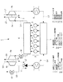
図1に示すように、本実施形態に係る舶用ディーゼル機関1は、ディーゼルエンジン本体(例えば、低速2サイクルディーゼル機関)2と、第1の排気タービン過給機(主排気タービン過給機)3と、第2の排気タービン過給機(副排気タービン過給機)4とを備えている。
ディーゼルエンジン本体(以下「エンジン本体」という。)2を構成するクランク軸(図示せず)には、プロペラ軸(図示せず)を介してスクリュープロペラ(図示せず)が直接的または間接的に取り付けられている。また、エンジン本体2には、シリンダライナ(図示せず)、シリンダカバー(図示せず)等からなるシリンダ部5が設けられており、各シリンダ部5内には、クランク軸と連結されたピストン(図示せず)が配置されている。さらに、各シリンダ部5の排気ポート(図示せず)は、排気マニホールド6と接続されており、排気マニホールド6は、第1の排気管L1を介して第1の排気タービン過給機(以下、「過給機A」という。)3のタービン部3aの入口側と接続され、第2の排気管L2を介して第2の排気タービン過給機(以下、「過給機B」という。)4のタービン部4aの入口側と接続されている。一方、各シリンダ部5の給気ポート(図示せず)は、給気マニホールド7と接続されており、給気マニホールド7は、第1の給気管L3を介して過給機A3のコンプレッサ部3bと接続され、第2の給気管L4を介して過給機B4のコンプレッサ部4bと接続されている。
As shown in FIG. 1, a
A screw propeller (not shown) is directly or indirectly connected to a crankshaft (not shown) constituting the diesel engine main body (hereinafter referred to as “engine main body”) 2 via a propeller shaft (not shown). It is attached. Further, the engine body 2 is provided with a
過給機A3は、第1の排気管L1を介してエンジン本体2から導かれた排気ガス(燃焼ガス)によって駆動されるタービン部3aと、このタービン部3aにより駆動されてエンジン本体2に外気を圧送するコンプレッサ部3bと、これらタービン部3aとコンプレッサ部3bとの間に設けられてこれらを支持するケーシング(図示せず)とを主たる要素として構成されたものである。
また、ケーシングには、一端部をタービン部3a側に突出させ、他端部をコンプレッサ部3bに突出させた回転軸3cが挿通されている。回転軸3cの一端部は、タービン部3aを構成するタービン・ロータ(図示せず)のタービン・ディスク(図示せず)に取り付けられており、回転軸3cの他端部は、コンプレッサ部3bを構成するコンプレッサ羽根車(図示せず)のハブ(図示せず)に取り付けられている。
The supercharger A3 is driven by exhaust gas (combustion gas) guided from the engine main body 2 via the first exhaust pipe L1, and is driven by the
In addition, the casing is inserted with a rotating shaft 3c having one end projecting toward the
過給機B4は、第2の排気管L2を介してエンジン本体2から導かれた排気ガス(燃焼ガス)によって駆動されるタービン部4aと、このタービン部4aにより駆動されてエンジン本体2に外気を圧送するコンプレッサ部4bと、これらタービン部4aとコンプレッサ部4bとの間に設けられてこれらを支持するケーシング(図示せず)とを主たる要素として構成されたものである。
また、ケーシングには、一端部をタービン部4a側に突出させ、他端部をコンプレッサ部4bに突出させた回転軸4cが挿通されている。回転軸4cの一端部は、タービン部4aを構成するタービン・ロータ(図示せず)のタービン・ディスク(図示せず)に取り付けられており、回転軸4cの他端部は、コンプレッサ部4bを構成するコンプレッサ羽根車(図示せず)のハブ(図示せず)に取り付けられている。
そして、タービン部3a,4aを通過した排気ガスはそれぞれ、タービン部3a,4aの出口側に接続された排気管L5,L6を介してファンネル(図示せず)に導かれた後、船外に排出されるようになっている。
The supercharger B4 is driven by exhaust gas (combustion gas) guided from the engine main body 2 via the second exhaust pipe L2, and is driven by the
Further, a rotating
The exhaust gas that has passed through the
コンプレッサ部3b,4bの入口側に接続された給気管L7,L8にはそれぞれ、消音器(図示せず)が配置されており、この消音器を通過した外気が、コンプレッサ部3b,4bにそれぞれ導かれるようになっている。また、コンプレッサ部3b,4bの出口側に接続された給気管L3,L4の途中には、空気冷却器(インタークーラ)8,9や図示しないサージタンク等が接続されており、コンプレッサ部3b,4bを通過した外気は、これら空気冷却器8,9やサージタンク等を通過した後、エンジン本体2の給気マニホールド7に供給されるようになっている。
A silencer (not shown) is arranged in each of the supply pipes L7 and L8 connected to the inlet side of the
さて、本実施形態に係る舶用ディーゼル機関1の第2の排気管L2の途中には、タービン入口弁10が接続され、第2の給気管L4(より詳しくは、コンプレッサ部4bと空気冷却器9とを結ぶ第2の給気管L4)の途中には、制御弁11が接続されており、制御弁11の上流側に位置する第2の給気管L4(より詳しくは、コンプレッサ部4bと制御弁11とを結ぶ第2の給気管L4)の途中には、空気放出管L9の一端が接続されている。空気放出管L9の他端は、排気管L6またはファンネルの途中に接続されており、空気放出管L9を通過した外気は、排気ガスとともに船外に排出されるようになっている。また、空気放出管L9の途中には、空気放出弁12が接続されている。
Now, in the middle of the second exhaust pipe L2 of the
そして、タービン入口弁10および空気放出弁12はそれぞれ、過給機A3を単独運転させている状態から、過給機B4を起動して、過給機A3と過給機B4とを並列運転させるとき、あるいは過給機A3と過給機B4とを並列運転させている状態から、過給機B4を停止して、過給機A3を単独運転させるときに手動で、または自動的に開閉される。
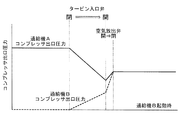
すなわち、図2に示すように、過給機A3を単独運転させている状態から、過給機B4を起動して、過給機A3と過給機B4とを並列運転させるときには、タービン入口弁10を開放し(全開とし)、予め開放しておいた空気放出弁12を徐々に閉めていく。そして、空気放出弁12を徐々に閉めていくことにより、過給機A3および過給機B4のコンプレッサ出口圧力が徐々に上昇し、過給機A3および過給機B4のコンプレッサ出口圧力が所定の圧力までそれぞれ高められることとなる。
なお、制御弁11は、過給機B4のコンプレッサ出口圧力が、給気マニホールド7の圧力以上になるか、あるいは給気マニホールド7の圧力と略等しくなると、又は、過給機B4のコンプレッサ出口圧力と給気マニホールド7の圧力との差圧が所定値以下になったときに開放(全開)するようになっている。
また、「過給機B4のコンプレッサ出口圧力と給気マニホールド7の圧力との差圧が所定値以下」という条件における「所定値」は、過給機B4のコンプレッサ出口圧力が給気マニホールド7の圧力を下回っていても、後に空気放出弁12を閉じた場合にコンプレッサ部4bから給気マニホールド7への空気流れが確保できる程度の差圧をいう。
Then, each of the
That is, as shown in FIG. 2, when the supercharger B4 is started from the state where the supercharger A3 is operated independently and the supercharger A3 and the supercharger B4 are operated in parallel, the
The
Further, the “predetermined value” under the condition that “the differential pressure between the compressor outlet pressure of the supercharger B4 and the pressure of the
一方、図3に示すように、過給機A3と過給機B4とを並列運転させている状態から、過給機B4を停止して、過給機A3を単独運転させるときには、空気放出弁12を徐々に開放し(全開とし)、給気マニホールド7の圧力が、過給機B4のコンプレッサ出口圧力(コンプレッサ部4bの出口圧力)よりも高くなるようにした後、タービン入口弁10を閉めていく。そして、タービン入口弁10を閉めていくことにより、過給機B4のコンプレッサ出口圧力が徐々に低下して0(零)となり、過給機B4が停止する。
なお、制御弁11は、過給機B4のコンプレッサ出口圧力が、給気マニホールド7の圧力よりも低くなるか、あるいは給気マニホールド7の圧力よりも所定の圧力低くなると、又は、過給機B4のコンプレッサ出口圧力と給気マニホールド7の圧力との差圧が所定値を超えたときに閉塞(全閉)するようになっている。
On the other hand, as shown in FIG. 3, when the supercharger A3 and the supercharger B4 are operated in parallel, when the supercharger B4 is stopped and the supercharger A3 is operated alone, the
The
本実施形態に係る舶用ディーゼル機関1によれば、第2の給気管L4に設けられた制御弁11は、過給機B4を起動して、過給機B4のコンプレッサ出口圧力(コンプレッサ部4bの出口圧力)が、給気マニホールド7の圧力以上になるか、あるいは給気マニホールド7の圧力と略等しくなると開放(全開)するようになっている。すなわち、過給機B4の起動時において、第2の給気管L4に設けられた制御弁11は、過給機B4のコンプレッサ出口圧力と給気マニホールド7の圧力との圧力差がなくなって、あるいは僅少となってから開くようになっている。
これにより、過給機B4の起動時における給気マニホールド7からコンプレッサ部4bへの逆流現象を防止する、あるいは大幅に低減させることができ、過給機B4(の回転軸4c)をスムーズに回転(起動)させることができて、過給機B4のサージングを防止することができる。
According to the
As a result, the backflow phenomenon from the
また、本実施形態に係る舶用ディーゼル機関1によれば、第2の給気管L4に設けられた制御弁11は、空気放出弁12を開けていき、過給機B4のコンプレッサ出口圧力(コンプレッサ部4bの出口圧力)が、給気マニホールド7の圧力よりも低くなるか、あるいは給気マニホールド7の圧力よりも所定の圧力低くなると閉塞(全閉)するようになっている。すなわち、過給機B4の停止時において、第2の給気管L4に設けられた制御弁11は、過給機B4のコンプレッサ出口圧力と給気マニホールド7の圧力との圧力差が所定の圧力よりも大きくなると閉まるようになっている。
これにより、過給機B4の停止時における給気マニホールド7からコンプレッサ部4bへの逆流現象を防止する、あるいは大幅に低減させることができ、過給機B4(の回転軸4c)をスムーズに回転(停止)させることができて、過給機B4のサージングを防止することができる。
Moreover, according to the
As a result, the backflow phenomenon from the
本発明に係る舶用ディーゼル機関の他の実施形態について、図4および図5を参照しながら説明する。
図4は本実施形態に係る舶用ディーゼル機関の概略構成図、図5は図4に示すタービン入口弁、空気放出弁、制御弁の開閉状態を示すバルブタイミングチャートである。
図4に示すように、本実施形態に係る舶用ディーゼル機関21は、差圧スイッチ22を備えているという点で上述した実施形態のものと異なる。その他の構成要素については上述した実施形態のものと同じであるので、ここではそれら構成要素についての説明は省略する。
Another embodiment of a marine diesel engine according to the present invention will be described with reference to FIGS.
FIG. 4 is a schematic configuration diagram of the marine diesel engine according to the present embodiment, and FIG. 5 is a valve timing chart showing open / closed states of the turbine inlet valve, the air release valve, and the control valve shown in FIG.
As shown in FIG. 4, the
差圧スイッチ22は、制御弁11の入口近傍における空気圧力P1と、制御弁11の出口近傍における空気圧力P2との差を検出し、これに基づいて制御弁11の開度を制御(調整)するものである。
すなわち、図5において左半分に示すように、過給機A3を単独運転させている状態から、過給機B4を起動して、過給機A3と過給機B4とを並列運転させるときには、タービン入口弁10を開放し(全開とし)、予め開放しておいた空気放出弁12を徐々に閉めていく。そして、空気放出弁12を徐々に閉めていくことにより、制御弁11の入口近傍における空気圧力P1が、制御弁11の出口近傍における空気圧力P2よりも大きくなったら差圧スイッチ22により制御弁11が徐々に開放され(全開とされ)、過給機A3および過給機B4のコンプレッサ出口圧力が徐々に上昇し、過給機A3および過給機B4のコンプレッサ出口圧力が所定の圧力までそれぞれ高められることとなる。
The
That is, as shown in the left half of FIG. 5, when the supercharger B4 is started from the state where the supercharger A3 is operated independently, and the supercharger A3 and the supercharger B4 are operated in parallel, The
一方、図5において右半分に示すように、過給機A3と過給機B4とを並列運転させている状態から、過給機B4を停止して、過給機A3を単独運転させるときには、空気放出弁12を徐々に開放し(全開とし)ていく。そして、空気放出弁12を徐々に開放していくことにより、制御弁11の出口近傍における空気圧力P2が、制御弁11の入口近傍における空気圧力P1よりも大きくなったら差圧スイッチ22により制御弁11が徐々に閉じられ(全閉とされ)、空気放出弁12が開放されたら(全開となったら)、タービン入口弁10を閉めていく。そして、タービン入口弁10を閉めていくことにより、過給機B4のコンプレッサ出口圧力が徐々に低下して0(零)となり、過給機B4が停止する。
On the other hand, as shown in the right half in FIG. 5, when the supercharger A3 and the supercharger B4 are operated in parallel, the supercharger B4 is stopped and the supercharger A3 is operated alone. The
本実施形態に係る舶用ディーゼル機関21によれば、制御弁11の入口近傍における空気圧力P1と、制御弁11の出口近傍における空気圧力P2との差を検出し、これに基づいて制御弁11の開度を制御する差圧スイッチ22が設けられているので、制御弁11を自動的に開閉させることができ、自動化を図ることができて、作業員の労力を軽減させることができる。
その他の作用効果は、上述した実施形態と同じであるので、ここではその説明を省略する。
According to the
Other functions and effects are the same as those in the above-described embodiment, and thus description thereof is omitted here.
なお、上述した実施形態では、過給機A3および過給機B4をそれぞれ一台ずつ具備した舶用ディーゼル機関について説明したが、本発明はこれに限定されるものではなく、過給機A3を2台以上および/または過給機B4を2台以上具備した舶用ディーゼル機関にも適用することができる。 In the above-described embodiment, the marine diesel engine provided with one supercharger A3 and one supercharger B4 has been described. However, the present invention is not limited to this, and two superchargers A3 are provided. It can also be applied to marine diesel engines equipped with two or more units and / or two or more superchargers B4.
1 舶用ディーゼル機関
2 エンジン本体
3 過給機A(主排気タービン過給機)
3a タービン部
3b コンプレッサ部
4 過給機B(副排気タービン過給機)
4a タービン部
4b コンプレッサ部
6 排気マニホールド
7 給気マニホールド
10 タービン入口弁
11 制御弁
12 空気放出弁
21 舶用ディーゼル機関
22 差圧スイッチ
L2 排気管
L4 給気管
L9 空気放出管
1 Marine Diesel Engine 2 Engine Body 3 Supercharger A (Main Exhaust Turbine Supercharger)
Claims (3)
前記エンジン本体から導かれた排気ガスによって駆動されるタービン部と、このタービン部により駆動されて前記エンジン本体に外気を圧送するコンプレッサ部とを有し、前記エンジン本体の運転中、常に運転状態とされる少なくとも一台の主排気タービン過給機と、
前記エンジン本体から導かれた排気ガスによって駆動されるタービン部と、このタービン部により駆動されて前記エンジン本体に外気を圧送するコンプレッサ部とを有し、前記エンジン本体の運転中、停止状態、または前記主排気タービン過給機と並列運転状態とされる少なくとも一台の副排気タービン過給機とを備えた舶用ディーゼル機関であって、
前記エンジン本体に搭載された排気マニホールドと、前記副排気タービン過給機のタービン部とを連通する排気管と、
前記排気管の途中に接続されたタービン入口弁と、
前記副排気タービン過給機のコンプレッサ部と前記エンジン本体に搭載された給気マニホールドとを連通する給気管と、
前記給気管の途中に接続され、前記副排気タービン過給機の前記コンプレッサ部の出口圧力が、前記給気マニホールドの圧力以上のとき、又は、前記コンプレッサ部の前記出口圧力と前記給気マニホールドの圧力との差圧が所定値以下になったときに開状態となり、前記給気マニホールドの圧力よりも低くなるか、あるいは前記給気マニホールドの圧力よりも所定の圧力低くなると、又は、前記コンプレッサ部の出口圧力と前記給気マニホールドの圧力との差圧が所定値を超えたときに閉状態となる制御弁と、
前記給気管の途中で、前記副排気タービン過給機のコンプレッサ部と前記制御弁との間にその一端が接続された空気放出管と、
前記空気放出管の途中に接続された空気放出弁とを備えてなることを特徴とする舶用ディーゼル機関。 One engine body,
A turbine unit driven by exhaust gas guided from the engine main body, and a compressor unit driven by the turbine unit to pump outside air to the engine main body. At least one main exhaust turbine supercharger,
A turbine section driven by exhaust gas guided from the engine body, and a compressor section driven by the turbine section to pump outside air to the engine body, and during operation of the engine body, A marine diesel engine comprising at least one sub-exhaust turbine supercharger in parallel operation with the main exhaust turbine supercharger,
An exhaust pipe that communicates an exhaust manifold mounted on the engine body and a turbine section of the sub-exhaust turbine supercharger;
A turbine inlet valve connected in the middle of the exhaust pipe;
An air supply pipe communicating the compressor section of the auxiliary exhaust turbine supercharger and an air supply manifold mounted on the engine body;
It is connected in the middle of the supply pipe, and when the outlet pressure of the compressor section of the auxiliary exhaust turbine supercharger is equal to or higher than the pressure of the supply manifold, or the outlet pressure of the compressor section and the supply manifold Ri Do the open state when the differential pressure between the pressure falls below a predetermined value, the air supply or manifold becomes lower than the pressure of, or the lower predetermined pressure than the pressure of the supply manifold, or the a closed state and name Ru control valve when the pressure difference between the outlet pressure and the pressure of the supply manifold of the compressor section exceeds a predetermined value,
In the middle of the air supply pipe, an air discharge pipe having one end connected between the compressor portion of the sub-exhaust turbine supercharger and the control valve;
A marine diesel engine comprising an air release valve connected in the middle of the air release pipe.
前記エンジン本体から導かれた排気ガスによって駆動されるタービン部と、このタービン部により駆動されて前記エンジン本体に外気を圧送するコンプレッサ部とを有し、前記エンジン本体の運転中、常に運転状態とされる少なくとも一台の主排気タービン過給機と、
前記エンジン本体から導かれた排気ガスによって駆動されるタービン部と、このタービン部により駆動されて前記エンジン本体に外気を圧送するコンプレッサ部とを有し、前記エンジン本体の運転中、停止状態とされるか、あるいは前記主排気タービン過給機と並列運転状態とされる少なくとも一台の副排気タービン過給機とを備え、
前記エンジン本体に搭載された排気マニホールドと、前記副排気タービン過給機のタービン部とを連通する排気管と、
前記排気管の途中に接続されたタービン入口弁と、
前記副排気タービン過給機のコンプレッサ部と前記エンジン本体に搭載された給気マニホールドとを連通する給気管と、
前記給気管の途中に接続され、前記副排気タービン過給機の前記コンプレッサ部の出口圧力が、前記給気マニホールドの圧力以上のとき、又は、前記コンプレッサ部の前記出口圧力と前記給気マニホールドの圧力との差圧が所定値以下になったときに開状態となり、前記給気マニホールドの圧力よりも低くなるか、あるいは前記給気マニホールドの圧力よりも所定の圧力低くなると、又は、前記コンプレッサ部の出口圧力と前記給気マニホールドの圧力との差圧が所定値を超えたときに閉状態となる制御弁と、
前記給気管の途中で、前記副排気タービン過給機のコンプレッサ部と前記制御弁との間にその一端が接続された空気放出管と、
前記空気放出管の途中に接続された空気放出弁とを備えた舶用ディーゼル機関の運転方法であって、
前記副排気タービン過給機の起動時には、前記空気放出弁を予め開放しておき、つぎに前記タービン入口弁を開けた後、前記空気放出弁を徐々に閉めていき、
前記副排気タービン過給機の停止時には、前記空気放出弁を徐々に開けていき、つぎに前記タービン入口弁を閉めるようにしたことを特徴とする舶用ディーゼル機関の運転方法。 One engine body,
A turbine unit driven by exhaust gas guided from the engine main body, and a compressor unit driven by the turbine unit to pump outside air to the engine main body. At least one main exhaust turbine supercharger,
A turbine section driven by exhaust gas guided from the engine body; and a compressor section driven by the turbine section for pumping outside air to the engine body, and is in a stopped state during operation of the engine body. Or at least one sub-exhaust turbine supercharger in parallel operation with the main exhaust turbine supercharger,
An exhaust pipe that communicates an exhaust manifold mounted on the engine body and a turbine section of the sub-exhaust turbine supercharger;
A turbine inlet valve connected in the middle of the exhaust pipe;
An air supply pipe communicating the compressor section of the auxiliary exhaust turbine supercharger and an air supply manifold mounted on the engine body;
It is connected in the middle of the supply pipe, and when the outlet pressure of the compressor section of the auxiliary exhaust turbine supercharger is equal to or higher than the pressure of the supply manifold, or the outlet pressure of the compressor section and the supply manifold Ri Do the open state when the differential pressure between the pressure falls below a predetermined value, the air supply or manifold becomes lower than the pressure of, or the lower predetermined pressure than the pressure of the supply manifold, or the a closed state and name Ru control valve when the pressure difference between the outlet pressure and the pressure of the supply manifold of the compressor section exceeds a predetermined value,
In the middle of the air supply pipe, an air discharge pipe having one end connected between the compressor portion of the sub-exhaust turbine supercharger and the control valve;
A marine diesel engine operating method comprising an air release valve connected in the middle of the air release pipe,
When starting up the sub exhaust turbine supercharger, open the air release valve in advance, then open the turbine inlet valve, then gradually close the air release valve,
A method of operating a marine diesel engine, wherein when the sub-exhaust turbine supercharger is stopped, the air discharge valve is gradually opened and then the turbine inlet valve is closed.
Priority Applications (1)
| Application Number | Priority Date | Filing Date | Title |
|---|---|---|---|
| JP2009237336A JP5448703B2 (en) | 2009-07-29 | 2009-10-14 | Marine diesel engine |
Applications Claiming Priority (3)
| Application Number | Priority Date | Filing Date | Title |
|---|---|---|---|
| JP2009176835 | 2009-07-29 | ||
| JP2009176835 | 2009-07-29 | ||
| JP2009237336A JP5448703B2 (en) | 2009-07-29 | 2009-10-14 | Marine diesel engine |
Publications (2)
| Publication Number | Publication Date |
|---|---|
| JP2011047393A JP2011047393A (en) | 2011-03-10 |
| JP5448703B2 true JP5448703B2 (en) | 2014-03-19 |
Family
ID=43833956
Family Applications (1)
| Application Number | Title | Priority Date | Filing Date |
|---|---|---|---|
| JP2009237336A Active JP5448703B2 (en) | 2009-07-29 | 2009-10-14 | Marine diesel engine |
Country Status (1)
| Country | Link |
|---|---|
| JP (1) | JP5448703B2 (en) |
Families Citing this family (5)
| Publication number | Priority date | Publication date | Assignee | Title |
|---|---|---|---|---|
| CN102979615A (en) * | 2012-11-19 | 2013-03-20 | 哈尔滨工程大学 | Diesel engine sequential turbocharging structure with anti-surge function |
| CN106068368B (en) * | 2014-04-24 | 2019-02-19 | 川崎重工业株式会社 | Engine system |
| JP5841641B2 (en) * | 2014-06-17 | 2016-01-13 | 川崎重工業株式会社 | Engine system |
| JP6650762B2 (en) * | 2016-01-15 | 2020-02-19 | 三菱重工業株式会社 | Internal combustion engine, control apparatus and method for internal combustion engine |
| US10746089B2 (en) * | 2018-01-25 | 2020-08-18 | Caterpillar Inc. | Inline turbocharger arrangement and method |
Family Cites Families (3)
| Publication number | Priority date | Publication date | Assignee | Title |
|---|---|---|---|---|
| JPS60166716A (en) * | 1984-02-08 | 1985-08-30 | Mitsubishi Heavy Ind Ltd | Supercharger selective operating method for diesel engine |
| JPH02298628A (en) * | 1989-05-12 | 1990-12-11 | Mazda Motor Corp | Controller for engine with supercharger |
| JP2590154Y2 (en) * | 1992-08-12 | 1999-02-10 | 株式会社ユニシアジェックス | Ignition timing control device for a supercharged internal combustion engine |
-
2009
- 2009-10-14 JP JP2009237336A patent/JP5448703B2/en active Active
Also Published As
| Publication number | Publication date |
|---|---|
| JP2011047393A (en) | 2011-03-10 |
Similar Documents
| Publication | Publication Date | Title |
|---|---|---|
| JP4950082B2 (en) | Marine diesel engine | |
| JP5155980B2 (en) | Turbo compound system and operation method thereof | |
| JP5448703B2 (en) | Marine diesel engine | |
| JP5173776B2 (en) | Exhaust energy recovery device | |
| JP2016017521A (en) | Forced introduction device for combustion engine, combustion engine and operation method for combustion engine | |
| US8307646B2 (en) | System using supplemental compressor for EGR | |
| US20120152214A1 (en) | Turbocharger system | |
| JP5804756B2 (en) | Supercharger system, internal combustion engine, and supercharger system control method | |
| JP2014098324A (en) | Supercharger for engine | |
| JP6370716B2 (en) | Supercharging system and operating method of supercharging system | |
| WO2013089158A1 (en) | Turbocharger exhaust entrance casing | |
| EP3263864B1 (en) | Engine start-up device, start-up method, and ship equipped with start-up device | |
| JP2005214095A (en) | Supercharger and supercharging method | |
| JPS631447B2 (en) | ||
| WO2018230108A1 (en) | Multi-stage supercharger | |
| KR20110129130A (en) | Internal combustion engine | |
| JP5449509B2 (en) | Exhaust energy recovery method and exhaust energy recovery device | |
| KR100921124B1 (en) | Two Stage Turbo System of Engine | |
| KR100201608B1 (en) | Apparatus for protecting turbo-rag | |
| JPS62279232A (en) | Internal combustion engine associated with supercharger | |
| JP2003129851A (en) | Engine supercharger of construction machinery | |
| JP2002188450A (en) | Exhaust gas temperature reduction method for internal combustion engine with supercharger, and its device | |
| KR20020024395A (en) | Turbo-charger system | |
| JPH01116225A (en) | Supercharger for engine |
Legal Events
| Date | Code | Title | Description |
|---|---|---|---|
| A621 | Written request for application examination |
Free format text: JAPANESE INTERMEDIATE CODE: A621 Effective date: 20120925 |
|
| A977 | Report on retrieval |
Free format text: JAPANESE INTERMEDIATE CODE: A971007 Effective date: 20130823 |
|
| A131 | Notification of reasons for refusal |
Free format text: JAPANESE INTERMEDIATE CODE: A131 Effective date: 20130827 |
|
| A521 | Written amendment |
Free format text: JAPANESE INTERMEDIATE CODE: A523 Effective date: 20131028 |
|
| TRDD | Decision of grant or rejection written | ||
| A01 | Written decision to grant a patent or to grant a registration (utility model) |
Free format text: JAPANESE INTERMEDIATE CODE: A01 Effective date: 20131126 |
|
| A61 | First payment of annual fees (during grant procedure) |
Free format text: JAPANESE INTERMEDIATE CODE: A61 Effective date: 20131224 |
|
| R151 | Written notification of patent or utility model registration |
Ref document number: 5448703 Country of ref document: JP Free format text: JAPANESE INTERMEDIATE CODE: R151 |