JP2009123793A - Cluster type vacuum processing equipment - Google Patents
Cluster type vacuum processing equipment Download PDFInfo
- Publication number
- JP2009123793A JP2009123793A JP2007293884A JP2007293884A JP2009123793A JP 2009123793 A JP2009123793 A JP 2009123793A JP 2007293884 A JP2007293884 A JP 2007293884A JP 2007293884 A JP2007293884 A JP 2007293884A JP 2009123793 A JP2009123793 A JP 2009123793A
- Authority
- JP
- Japan
- Prior art keywords
- processing
- chamber
- memory
- type vacuum
- cluster type
- Prior art date
- Legal status (The legal status is an assumption and is not a legal conclusion. Google has not performed a legal analysis and makes no representation as to the accuracy of the status listed.)
- Pending
Links
Images

Landscapes
- Chemical Vapour Deposition (AREA)
Abstract
Description
本発明は、クラスタチャンバ構造の真空処理装置の制御に関し、特には、各処理用パラメータを保存する場所と同時処理の多重化に関する。 The present invention relates to control of a vacuum processing apparatus having a cluster chamber structure, and more particularly to multiplexing of simultaneous processing with a place where each processing parameter is stored.
半導体デバイス製造装置や各種成膜処理装置などにおける真空処理は、被処理物を大気中から真空の処理室に搬送したり、処理後の被処理物を真空の処理室から大気中へ搬送する工程が不可欠であり、搬送の度に排気とリークを繰り返すことになる。 Vacuum processing in a semiconductor device manufacturing apparatus or various film forming processing apparatuses is a process of transferring an object to be processed from the atmosphere to a vacuum processing chamber, or transferring a processed object to be processed from the vacuum processing chamber to the atmosphere. Is indispensable, and exhaust and leak are repeated at every conveyance.
一方、1台の装置に異なる複数の処理室を備えて順番に真空処理を行う際に被処理物の搬送を真空中で行うクラスタ型真空処理装置が知られている(例えば、特許文献1参照)。この装置では、搬送室に対して複数の処理室がゲート弁を介して配置されており、搬送室内と処理室内は常時真空を保ち、大気開放をせずに、搬送室を介して被処理物を処理室から次の処理室へ搬送することができる。また、搬送室は、大気開放と真空密閉の切り換えができるロードロック室にゲート弁を介して接続されている。
従来、パーソナルコンピュータを備えたクラスタ型真空処理装置の基本制御はPLC(Programmable Logic Controller(以下単にPLCという))またはオンボードコントローラにより行われ、全ての処理工程の処理用パラメータはPLCまたはオンボードコントローラのメモリに保存されている。しかし、PLCまたはオンボードコントローラのメモリ容量は少なく、処理工程の増加や処理室の増設・改造及び同時処理ワーク数に制限がある。また、パーソナルコンピュータのみでの制御では信頼性に問題がある。 Conventionally, basic control of a cluster type vacuum processing apparatus equipped with a personal computer has been performed by a PLC (Programmable Logic Controller (PLC)) or an on-board controller, and processing parameters for all processing steps are performed by the PLC or the on-board controller. Stored in the memory. However, the memory capacity of the PLC or on-board controller is small, and there is a limit to the increase in processing steps, expansion / modification of processing chambers, and the number of simultaneous processing works. In addition, there is a problem in reliability in the control using only the personal computer.
複数個の処理室を環状に配設し各処理室に被処理物を順次移送させ処理工程にしたがって真空処理を行うクラスタ型真空処理装置において、全ての処理工程の処理用パラメータをメモリに保存するパーソナルコンピュータと、プログラム可能な制御器を備え、処理工程の開始時その処理用パラメータを前記プログラム可能な制御器に転送する。プログラム可能な制御器はPLCあるいはオンボードコントローラなどで構成される。したがって、大量の処理用パラメータを保存することができる。 In a cluster type vacuum processing apparatus in which a plurality of processing chambers are arranged in a ring shape, and workpieces are sequentially transferred to each processing chamber and vacuum processing is performed according to the processing steps, processing parameters for all processing steps are stored in a memory. A personal computer and a programmable controller are provided, and processing parameters are transferred to the programmable controller at the start of the process. The programmable controller is composed of a PLC or an on-board controller. Therefore, a large amount of processing parameters can be stored.
容量の大きなパーソナルコンピュータのメモリに全ての処理工程の処理用パラメータを保存し、必要に応じてPLCまたはオンボードコントローラへ転送して装置を制御することができる。したがって、処理工程の増加や処理室の増設・改造及び同時処理ワーク数に制限がなくなり、信頼性も維持される。 Processing parameters for all processing steps can be stored in the memory of a large-capacity personal computer and transferred to the PLC or on-board controller as needed to control the apparatus. Therefore, there is no limit to the number of processing steps, the expansion / modification of processing chambers, and the number of simultaneous processing workpieces, and reliability is maintained.
パーソナルコンピュータは、全ての処理工程の処理用パラメータをメモリに保存し、ユーザーインタフェースとして機能する。 The personal computer stores processing parameters for all processing steps in a memory and functions as a user interface.
パーソナルコンピュータとPLCまたはオンボードコントローラ間の信号またはデータの伝送系としてはシリアル通信が用いられる。 Serial communication is used as a signal or data transmission system between the personal computer and the PLC or on-board controller.
本発明の実施例について図1〜3を参照して説明する。図1は、本発明の実施例によるクラスタ型真空処理装置の概略構成図である。図2は、本発明の実施例によるメモリ構成の概略を示す図である。図3は、本発明の実施例による動作の概略を示す図である。 An embodiment of the present invention will be described with reference to FIGS. FIG. 1 is a schematic configuration diagram of a cluster type vacuum processing apparatus according to an embodiment of the present invention. FIG. 2 is a diagram showing an outline of a memory configuration according to the embodiment of the present invention. FIG. 3 is a diagram showing an outline of the operation according to the embodiment of the present invention.
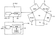
本発明のクラスタ型真空処理装置は、図1に示すように、全ての処理工程の処理用パラメータをメモリに保存し、ユーザーインタフェースとして機能するPC(パーソナルコンピュータ)1と、装置の基本制御をし、各処理室(チャンバ)の真空処理の工程を制御するPLC(Programmable Logic Controller)2と、被処理物(ワーク)の搬送をするTCチャンバ3と、ワークの搬入出をするLL(ロードロック)チャンバ4と、エッチング工程を真空処理するIBEチャンバ5と、シリコン成膜工程を真空処理するPS/SPチャンバ6と、カーボン成膜工程を真空処理するECRチャンバ7と、耐磨耗膜成膜工程を真空処理するFCVAチャンバ8で構成され、真空処理する処理室(チャンバ)は4室あり、最大同時処理ワーク数は4ワークである。
As shown in FIG. 1, the cluster type vacuum processing apparatus of the present invention stores processing parameters for all processing steps in a memory, and performs basic control of the apparatus and a PC (personal computer) 1 functioning as a user interface. , PLC (Programmable Logic Controller) 2 for controlling the vacuum processing process of each processing chamber (chamber),
PC1は、CPU(Central Processing Unit)11と、RAM(Random Access Memory)とHDD(Hard Disk Drive)で構成される例えば記憶容量数十GBのメモリ12を備えている。PLC2は、CPU21と、バッテリ保持型RAMで構成される例えば記憶容量約8000word(約16KB)のメモリ22を備えている。
The
本発明の実施例によるクラスタ型真空処理装置の動作を図2、3を参照して説明する。ステップS1、操作者は各ワーク(実施例の場合ワーク1〜3)の処理工程記号(A〜Z)をPC1上で選択し転送操作をする。1wordの処理工程記号(A〜Z)によりワークを処理するチャンバと処理工程の種類とその順番が決定する。一つのチャンバには複数の処理工程が存在するが処理工程記号により一つが選択される。ステップS2、PC1はワーク1〜3の処理工程記号をPLC2に転送する。ステップS3、PLC2はPC1から受け取ったワーク1〜3の処理工程記号を一時ファイルレジスタ(1word)を介してメモリ22へ保存する(ワーク1〜3で3word必要)。
The operation of the cluster type vacuum processing apparatus according to the embodiment of the present invention will be described with reference to FIGS. In step S1, the operator selects a process step symbol (A to Z) of each workpiece (works 1 to 3 in the embodiment) on the
ステップS4、PLC2はワーク1の処理工程記号に従い、処理工程1の準備(ワーク1をLLチャンバ4へ搬入し真空引き後、TCチャンバ3を介して処理工程1を処理するチャンバへ搬送)をする。ステップS5、PLC2はワーク1の処理工程1の準備完了をPC1に送信する。ステップS6、PC1はPLC2へワーク1の処理工程1を処理するチャンバの処理用パラメータ(140word)を転送する。ステップS7、PLC2はPC1からワーク1の処理工程1を処理するチャンバの処理用パラメータ(140word)を受け取りメモリ22へ保存する。
In step S4, PLC2 prepares for the
ステップS8、PLC2は受け取った処理用パラメータでワーク1の処理工程1を開始し、終了後、処理工程2の準備(ワーク1をTCチャンバ3を介して処理工程2を処理するチャンバへ搬送)をする。ステップS9、PLC2はワーク1の処理工程2の準備完了をPC1に送信する。ステップS10、PC1はPLC2へワーク1の処理工程2を処理するチャンバの処理用パラメータ(140word)を転送する。ステップS11、PLC2はPC1からワーク1の処理工程2を処理するチャンバの処理用パラメータ(140word)を受け取りメモリ22へ保存する。ステップS12、PLC2は受け取った処理用パラメータでワーク1の処理工程2を開始する。
Step S8,
ステップS13、PLC2はワーク2の処理工程記号に従い、処理工程1の準備(ワーク2をLLチャンバ4へ搬入し真空引き後、TCチャンバ3を介して処理工程1を処理するチャンバへ搬送)をする。ステップS14、PLC2はワーク2の処理工程1の準備完了をPC1に送信する。ステップS15、PC1はPLC2へワーク2の処理工程1を処理するチャンバの処理用パラメータ(140word)を転送する。ステップS16、PLC2はPC1からワーク2の処理工程1を処理するチャンバの処理用パラメータ(140word)を受け取りメモリ22へ保存する。
Step S13, PLC2 prepares for the
ステップS17、PLC2は受け取った処理用パラメータでワーク2の処理工程1を開始する。以下、同様に処理が進行する。ただし、ワーク1〜3が同時に同じチャンバで処理が行われることがないように管理されている。
In step S17, PLC2 starts the
本発明は以上の構成であるから、PLC2はIBEチャンバ5と、PS/SPチャンバ6と、ECRチャンバ7と、FCVAチャンバ8の4個のチャンバを夫々の処理用パラメータを使って制御して成膜等の処理工程を進める。この処理用パラメータは処理工程の開始時にPC1から都度転送されメモリ22に保存されるが、4個のチャンバに対応している。PLC2のメモリ22に保存されるデータとその容量は、図2に示すように、同時処理するワーク数を3個とすると、一時ファイルレジスタ(1word)と、処理工程記号(1word)3個と、処理用パラメータ(140word)4個であり、容量の合計は564wordである。PLC2のメモリ22の記憶容量は約8000wordであり、十分余裕がある。したがって、処理工程の増加や処理室の増設・改造及び同時処理ワーク数の増加があっても、信頼性の高いPLC2よる装置制御で対応できる。
Since the present invention has the above configuration, the
図1に示す実施例においては、ワークの搬送をするTCチャンバ3の周辺に5個のチャンバが配置されているが、この個数はこれより多くても少なくても本発明は適用可能である。また、装置の基本制御はPLC2により行われているが、代わりにオンボードコントローラあるいはシーケンスコントローラなどで行われても本発明は適用可能であり装置は図示例に限定されない。
In the embodiment shown in FIG. 1, five chambers are arranged around the
本発明は、クラスタチャンバ構造の真空処理装置の制御に関し、特には、各処理用パラメータを保存する場所と同時処理の多重化に関する。 The present invention relates to control of a vacuum processing apparatus having a cluster chamber structure, and more particularly to multiplexing of simultaneous processing with a place where each processing parameter is stored.
1 PC
2 PLC
3 TCチャンバ
4 LLチャンバ
5 IBEチャンバ
6 PS/SPチャンバ
7 ECRチャンバ
8 FCVAチャンバ
11 CPU
12 メモリ
21 CPU
22 メモリ
1 PC
2 PLC
3
12
22 memory
Claims (3)
Priority Applications (1)
| Application Number | Priority Date | Filing Date | Title |
|---|---|---|---|
| JP2007293884A JP2009123793A (en) | 2007-11-13 | 2007-11-13 | Cluster type vacuum processing equipment |
Applications Claiming Priority (1)
| Application Number | Priority Date | Filing Date | Title |
|---|---|---|---|
| JP2007293884A JP2009123793A (en) | 2007-11-13 | 2007-11-13 | Cluster type vacuum processing equipment |
Publications (1)
| Publication Number | Publication Date |
|---|---|
| JP2009123793A true JP2009123793A (en) | 2009-06-04 |
Family
ID=40815656
Family Applications (1)
| Application Number | Title | Priority Date | Filing Date |
|---|---|---|---|
| JP2007293884A Pending JP2009123793A (en) | 2007-11-13 | 2007-11-13 | Cluster type vacuum processing equipment |
Country Status (1)
| Country | Link |
|---|---|
| JP (1) | JP2009123793A (en) |
Citations (5)
| Publication number | Priority date | Publication date | Assignee | Title |
|---|---|---|---|---|
| JP2001143980A (en) * | 1999-06-01 | 2001-05-25 | Applied Materials Inc | Semiconductor processing technology |
| JP2005150324A (en) * | 2003-11-14 | 2005-06-09 | Ulvac Japan Ltd | Method and device for sheet vacuum treatment |
| JP2006278396A (en) * | 2005-03-28 | 2006-10-12 | Tokyo Electron Ltd | Processing apparatus and program |
| JP2007019431A (en) * | 2005-07-11 | 2007-01-25 | Tokyo Electron Ltd | Substrate processing monitoring device, substrate processing monitoring system, substrate processing monitoring program, and recording medium |
| WO2007046204A1 (en) * | 2005-10-19 | 2007-04-26 | Tokyo Electron Limited | Substrate treating apparatus, method of substrate treatment, program, and recording medium in which program is recorded |
-
2007
- 2007-11-13 JP JP2007293884A patent/JP2009123793A/en active Pending
Patent Citations (5)
| Publication number | Priority date | Publication date | Assignee | Title |
|---|---|---|---|---|
| JP2001143980A (en) * | 1999-06-01 | 2001-05-25 | Applied Materials Inc | Semiconductor processing technology |
| JP2005150324A (en) * | 2003-11-14 | 2005-06-09 | Ulvac Japan Ltd | Method and device for sheet vacuum treatment |
| JP2006278396A (en) * | 2005-03-28 | 2006-10-12 | Tokyo Electron Ltd | Processing apparatus and program |
| JP2007019431A (en) * | 2005-07-11 | 2007-01-25 | Tokyo Electron Ltd | Substrate processing monitoring device, substrate processing monitoring system, substrate processing monitoring program, and recording medium |
| WO2007046204A1 (en) * | 2005-10-19 | 2007-04-26 | Tokyo Electron Limited | Substrate treating apparatus, method of substrate treatment, program, and recording medium in which program is recorded |
Similar Documents
| Publication | Publication Date | Title |
|---|---|---|
| JP5282021B2 (en) | Semiconductor processing system and semiconductor processing method | |
| KR102385670B1 (en) | Substrate transfer method and substrate processing apparatus | |
| US8571703B2 (en) | System, method and storage medium for controlling a processing system | |
| JP2014078576A (en) | Vacuum processing device and vacuum processing method | |
| JP2011091430A (en) | Wafer handler method and system | |
| EP1268875A2 (en) | Method and apparatus for reducing contamination in a loadlock | |
| JP2013098412A (en) | Vacuum processing apparatus and method for conveying object to be processed | |
| US10403532B2 (en) | Semiconductor apparatus with inner wafer carrier buffer and method | |
| JP2014179431A5 (en) | ||
| JP2016207767A (en) | Substrate processing system | |
| JP2016096211A (en) | Vacuum processing apparatus | |
| JP2014036025A (en) | Vacuum processing apparatus or operation method of vacuum processing apparatus | |
| JP2009123793A (en) | Cluster type vacuum processing equipment | |
| WO2020008955A1 (en) | Substrate processing device and substrate processing method | |
| JP4545147B2 (en) | Substrate processing apparatus and semiconductor device manufacturing method | |
| CN103996644A (en) | Process management method for multi-cavity equipment | |
| KR102166968B1 (en) | Processing method and processing device | |
| JP5947030B2 (en) | Substrate processing method and substrate processing apparatus | |
| JP5997542B2 (en) | Vacuum processing apparatus and vacuum processing method | |
| JP2009076495A (en) | Vacuum processing equipment | |
| JP2004087600A (en) | Multi-chamber system and processing method using multi-chamber system | |
| JP2014120618A (en) | Vacuum processing apparatus and vacuum processing method | |
| JP2006313934A (en) | Semiconductor manufacturing apparatus and film forming method for semiconductor manufacturing apparatus | |
| KR101208696B1 (en) | apparatus for producing semiconductor and method for controlling chamber thereof | |
| KR100587680B1 (en) | Semiconductor Process Control System |
Legal Events
| Date | Code | Title | Description |
|---|---|---|---|
| A621 | Written request for application examination |
Free format text: JAPANESE INTERMEDIATE CODE: A621 Effective date: 20100219 |
|
| A131 | Notification of reasons for refusal |
Free format text: JAPANESE INTERMEDIATE CODE: A131 Effective date: 20120807 |
|
| A02 | Decision of refusal |
Free format text: JAPANESE INTERMEDIATE CODE: A02 Effective date: 20121205 |