JP2009114872A - Exhaust emission control device - Google Patents
Exhaust emission control device Download PDFInfo
- Publication number
- JP2009114872A JP2009114872A JP2007285693A JP2007285693A JP2009114872A JP 2009114872 A JP2009114872 A JP 2009114872A JP 2007285693 A JP2007285693 A JP 2007285693A JP 2007285693 A JP2007285693 A JP 2007285693A JP 2009114872 A JP2009114872 A JP 2009114872A
- Authority
- JP
- Japan
- Prior art keywords
- exhaust gas
- gas passage
- filter device
- dust collecting
- discharge electrode
- Prior art date
- Legal status (The legal status is an assumption and is not a legal conclusion. Google has not performed a legal analysis and makes no representation as to the accuracy of the status listed.)
- Withdrawn
Links
Images


Classifications
-
- B—PERFORMING OPERATIONS; TRANSPORTING
- B03—SEPARATION OF SOLID MATERIALS USING LIQUIDS OR USING PNEUMATIC TABLES OR JIGS; MAGNETIC OR ELECTROSTATIC SEPARATION OF SOLID MATERIALS FROM SOLID MATERIALS OR FLUIDS; SEPARATION BY HIGH-VOLTAGE ELECTRIC FIELDS
- B03C—MAGNETIC OR ELECTROSTATIC SEPARATION OF SOLID MATERIALS FROM SOLID MATERIALS OR FLUIDS; SEPARATION BY HIGH-VOLTAGE ELECTRIC FIELDS
- B03C3/00—Separating dispersed particles from gases or vapour, e.g. air, by electrostatic effect
- B03C3/02—Plant or installations having external electricity supply
- B03C3/04—Plant or installations having external electricity supply dry type
- B03C3/06—Plant or installations having external electricity supply dry type characterised by presence of stationary tube electrodes
-
- B—PERFORMING OPERATIONS; TRANSPORTING
- B03—SEPARATION OF SOLID MATERIALS USING LIQUIDS OR USING PNEUMATIC TABLES OR JIGS; MAGNETIC OR ELECTROSTATIC SEPARATION OF SOLID MATERIALS FROM SOLID MATERIALS OR FLUIDS; SEPARATION BY HIGH-VOLTAGE ELECTRIC FIELDS
- B03C—MAGNETIC OR ELECTROSTATIC SEPARATION OF SOLID MATERIALS FROM SOLID MATERIALS OR FLUIDS; SEPARATION BY HIGH-VOLTAGE ELECTRIC FIELDS
- B03C3/00—Separating dispersed particles from gases or vapour, e.g. air, by electrostatic effect
- B03C3/02—Plant or installations having external electricity supply
- B03C3/04—Plant or installations having external electricity supply dry type
- B03C3/14—Plant or installations having external electricity supply dry type characterised by the additional use of mechanical effects, e.g. gravity
- B03C3/15—Centrifugal forces
-
- B—PERFORMING OPERATIONS; TRANSPORTING
- B03—SEPARATION OF SOLID MATERIALS USING LIQUIDS OR USING PNEUMATIC TABLES OR JIGS; MAGNETIC OR ELECTROSTATIC SEPARATION OF SOLID MATERIALS FROM SOLID MATERIALS OR FLUIDS; SEPARATION BY HIGH-VOLTAGE ELECTRIC FIELDS
- B03C—MAGNETIC OR ELECTROSTATIC SEPARATION OF SOLID MATERIALS FROM SOLID MATERIALS OR FLUIDS; SEPARATION BY HIGH-VOLTAGE ELECTRIC FIELDS
- B03C3/00—Separating dispersed particles from gases or vapour, e.g. air, by electrostatic effect
- B03C3/34—Constructional details or accessories or operation thereof
- B03C3/36—Controlling flow of gases or vapour
- B03C3/361—Controlling flow of gases or vapour by static mechanical means, e.g. deflector
-
- B—PERFORMING OPERATIONS; TRANSPORTING
- B03—SEPARATION OF SOLID MATERIALS USING LIQUIDS OR USING PNEUMATIC TABLES OR JIGS; MAGNETIC OR ELECTROSTATIC SEPARATION OF SOLID MATERIALS FROM SOLID MATERIALS OR FLUIDS; SEPARATION BY HIGH-VOLTAGE ELECTRIC FIELDS
- B03C—MAGNETIC OR ELECTROSTATIC SEPARATION OF SOLID MATERIALS FROM SOLID MATERIALS OR FLUIDS; SEPARATION BY HIGH-VOLTAGE ELECTRIC FIELDS
- B03C3/00—Separating dispersed particles from gases or vapour, e.g. air, by electrostatic effect
- B03C3/34—Constructional details or accessories or operation thereof
- B03C3/40—Electrode constructions
- B03C3/41—Ionising-electrodes
-
- B—PERFORMING OPERATIONS; TRANSPORTING
- B03—SEPARATION OF SOLID MATERIALS USING LIQUIDS OR USING PNEUMATIC TABLES OR JIGS; MAGNETIC OR ELECTROSTATIC SEPARATION OF SOLID MATERIALS FROM SOLID MATERIALS OR FLUIDS; SEPARATION BY HIGH-VOLTAGE ELECTRIC FIELDS
- B03C—MAGNETIC OR ELECTROSTATIC SEPARATION OF SOLID MATERIALS FROM SOLID MATERIALS OR FLUIDS; SEPARATION BY HIGH-VOLTAGE ELECTRIC FIELDS
- B03C3/00—Separating dispersed particles from gases or vapour, e.g. air, by electrostatic effect
- B03C3/34—Constructional details or accessories or operation thereof
- B03C3/40—Electrode constructions
- B03C3/45—Collecting-electrodes
- B03C3/49—Collecting-electrodes tubular
-
- B—PERFORMING OPERATIONS; TRANSPORTING
- B03—SEPARATION OF SOLID MATERIALS USING LIQUIDS OR USING PNEUMATIC TABLES OR JIGS; MAGNETIC OR ELECTROSTATIC SEPARATION OF SOLID MATERIALS FROM SOLID MATERIALS OR FLUIDS; SEPARATION BY HIGH-VOLTAGE ELECTRIC FIELDS
- B03C—MAGNETIC OR ELECTROSTATIC SEPARATION OF SOLID MATERIALS FROM SOLID MATERIALS OR FLUIDS; SEPARATION BY HIGH-VOLTAGE ELECTRIC FIELDS
- B03C2201/00—Details of magnetic or electrostatic separation
- B03C2201/10—Ionising electrode has multiple serrated ends or parts
-
- B—PERFORMING OPERATIONS; TRANSPORTING
- B03—SEPARATION OF SOLID MATERIALS USING LIQUIDS OR USING PNEUMATIC TABLES OR JIGS; MAGNETIC OR ELECTROSTATIC SEPARATION OF SOLID MATERIALS FROM SOLID MATERIALS OR FLUIDS; SEPARATION BY HIGH-VOLTAGE ELECTRIC FIELDS
- B03C—MAGNETIC OR ELECTROSTATIC SEPARATION OF SOLID MATERIALS FROM SOLID MATERIALS OR FLUIDS; SEPARATION BY HIGH-VOLTAGE ELECTRIC FIELDS
- B03C2201/00—Details of magnetic or electrostatic separation
- B03C2201/30—Details of magnetic or electrostatic separation for use in or with vehicles
Abstract
Description
本発明は、ディーゼルエンジン、ガソリンエンジン等の排ガス中に含まれる粒子状物質(パティキュレートマター、以下PMという)などの除去を行う排ガス浄化装置に関する。 The present invention relates to an exhaust gas purification apparatus that removes particulate matter (particulate matter, hereinafter referred to as PM) contained in exhaust gas of a diesel engine, a gasoline engine, or the like.
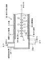
図5は、特許文献1(WO2005/021161号公報)に開示された電気式集塵装置の例を示す概略断面図である。
図5において、集塵装置100は、筒状の外殻1と、放電極主部4及び放電極放電部3からなる放電電極40と、集塵極及び集塵フィルタ層からなる集塵フィルタ装置2とを備えている。放電電極40は、高圧導線5a及び碍子5を介して高電圧発生装置20に接続されている。また、碍子5は、碍子室6内に収納されている。
FIG. 5 is a schematic cross-sectional view showing an example of an electric dust collector disclosed in Patent Document 1 (WO2005 / 021161).
In FIG. 5, a
上記外殻1は筒状に形成され、その内部はPMを含む排ガスが流れる排ガス通路7となっており、排ガスは、排ガス通路7を放電電極40に沿って、図5中の矢印のように流れるようになっている。このため、放電電極40は、排ガス通路7の中央を排ガス流の方向に沿って延在する放電極主部4と、該放電極主部4から排ガス通路7を横切って集塵フィルタ装置2の側に向かって延びる刺状に形成された複数の放電極放電部3とから構成されている。
The
このような集塵装置100においては、高電圧発生装置20からの高電圧を、高圧導線5aを介して放電電極40に印加すると、放電極主部4及び複数の放電極放電部3から集塵フィルタ装置2の集塵極に向けて飛び出すイオンに誘起されたイオン風が生じる。これによって、排ガス流中に含まれるPMの大部分は集塵極を通り、該PMはガスとともに集塵極の外側に配置された集塵フィルタ層に導かれ、該集塵フィルタ層にてPMの大部分が捕集され、浄化ガスになる。
In such a
一般に、ディーゼルエンジン等の排ガス中のPMを除去して浄化処理を行うには、黒鉛除去装置であるディーゼルパティキュレートフィルタ(以下、DPFという)が利用されている。しかしながら、かかるDPFには、次々のような問題点がある。
すなわち、経時的に、DPFでは、フィルタの目詰まりにより圧力損失が上昇し、これにより排気側に負荷が掛かり、燃料消費効率が上昇するとともに、エンジン出力の低下を来たす、などの悪影響を及ぼすことになる。しかも、このフィルタの目詰まりがさらに進行すると、エンジン停止の事態が発生するおそれがある。
In general, a diesel particulate filter (hereinafter referred to as DPF), which is a graphite removing device, is used to remove PM in exhaust gas from a diesel engine or the like and perform purification treatment. However, such DPF has the following problems.
In other words, over time, in the DPF, pressure loss increases due to clogging of the filter, which causes a load on the exhaust side, fuel consumption efficiency increases, and engine output decreases. become. Moreover, if the filter is further clogged, there is a possibility that the engine will stop.
そこで先行技術として、上記特許文献1のような、PMを低圧力損失で処理可能な電気式集塵装置が採用されている。しかしながら、この電気式集塵装置には、次のような解決すべき問題がある。
(1)排ガス通路7に導入される排ガスは、整流された均一な流れであり、放電電極40を構成する刺状の放電極放電部3の先端部にPMが付着しやすく、当該PMの付着により、放電電流が抑制されて、電気式集塵装置100の捕集効率が低下することになる。
(2)碍子5の表面が、残存PMで経時的に汚れるので、絶縁が保持できなくなり、所定の電圧が印加できなくなる。
(3)DPFに比較すると、捕集効率が低く、捕集効率の改善が必要である。
(4)排ガス中のPMは、イオン風により排ガス流れと直交する方向に移動させられて集塵極外側の集塵フィルタ層に捕集されるが、電極断面の中心位置ほどPMが移動する距離が長くなるとともに、主流の軸方向の速度ベクトルが速いほど中心近傍のPMの捕集性能が低下することになる。
Therefore, as a prior art, an electric dust collector capable of processing PM with a low pressure loss, such as
(1) The exhaust gas introduced into the
(2) Since the surface of the
(3) Compared with DPF, the collection efficiency is low and the collection efficiency needs to be improved.
(4) The PM in the exhaust gas is moved in a direction orthogonal to the exhaust gas flow by the ion wind and collected in the dust collection filter layer outside the dust collection electrode, but the distance the PM moves toward the center position of the electrode cross section The longer the mainstream axial velocity vector, the lower the PM collection performance near the center.
本発明は、このような実状に鑑みてなされたものであり、その目的は、放電電極を構成する刺状の放電極放電部から集塵フィルタ装置側へ向かうイオン風及び排ガス中のPMの移動距離を短くすることによって、PMの捕集効率を向上させた排ガス浄化装置を提供することにある。 The present invention has been made in view of such a situation, and an object of the present invention is to move the ion wind and the PM in the exhaust gas from the stab-like discharge electrode discharge portion constituting the discharge electrode toward the dust collecting filter device side. An object of the present invention is to provide an exhaust gas purifying apparatus that improves the PM collection efficiency by shortening the distance.
上記従来技術の有する課題を解決するために、本発明は、筒形状をなす外殻と、前記外殻内に沿って配置され、集塵極及び集塵フィルタ層からなる集塵フィルタ装置と、前記集塵フィルタ装置の内側に形成され、粒子状物質を含む排ガスが流れる排ガス通路と、前記排ガス通路中に該排ガス通路を横切る方向に互いに先端を離した状態で設置され、電圧が印加されたときに前記集塵フィルタ装置との間に前記排ガス流と直交する方向に2次流れを誘起形成するイオン風を発生させる放電電極とを備えた排ガス浄化装置において、前記放電電極の上流側に位置する前記外殻には、前記排ガス通路に対して接線方向に開口する排ガスの旋回流形成管が設けられている。 In order to solve the above-described problems of the prior art, the present invention includes a cylindrical outer shell, a dust collecting filter device that is disposed along the outer shell and includes a dust collecting electrode and a dust collecting filter layer. An exhaust gas passage formed inside the dust collecting filter device through which exhaust gas containing particulate matter flows and a tip of the exhaust gas passage in the direction crossing the exhaust gas passage are separated from each other and a voltage is applied. An exhaust gas purification apparatus comprising a discharge electrode that generates an ionic wind that induces and forms a secondary flow in a direction orthogonal to the exhaust gas flow between the dust collection filter device and a position on the upstream side of the discharge electrode. The outer shell is provided with an exhaust gas swirl flow pipe that opens in a tangential direction with respect to the exhaust gas passage.
本発明において、前記旋回流形成管は、前記排ガス通路への開口端が前記排ガス通路の中心に対して対向するように設けられていることが好ましい。 In the present invention, it is preferable that the swirl flow forming pipe is provided so that an opening end to the exhaust gas passage is opposed to a center of the exhaust gas passage.
また、本発明は、筒形状をなす外殻と、前記外殻内に沿って配置され、集塵極及び集塵フィルタ層からなる集塵フィルタ装置と、前記集塵フィルタ装置の内側に形成され、粒子状物質を含む排ガスが流れる排ガス通路と、前記排ガス通路中に該排ガス通路を横切る方向に互いに先端を離した状態で設置され、電圧が印加されたときに前記集塵フィルタ装置との間に前記排ガス流と直交する方向に2次流れを誘起形成するイオン風を発生させる放電電極とを備えた排ガス浄化装置において、前記排ガス通路中で、前記放電電極の上流側には、前記排ガス流を衝突させた後に該排ガス流を前記集塵フィルタ装置側に偏向させる案内部材が設けられている。 The present invention also includes a cylindrical outer shell, a dust collecting filter device that is disposed along the outer shell and includes a dust collecting electrode and a dust collecting filter layer, and is formed inside the dust collecting filter device. An exhaust gas passage through which exhaust gas containing particulate matter flows, and the dust collection filter device when a voltage is applied between the exhaust gas passage and the exhaust gas passage installed in a direction across the exhaust gas passage. In the exhaust gas purification apparatus, the discharge electrode for generating an ionic wind that induces and forms a secondary flow in a direction orthogonal to the exhaust gas flow is disposed upstream of the discharge electrode in the exhaust gas passage. A guide member is provided for deflecting the exhaust gas flow toward the dust collecting filter device after the collision.
さらに、本発明は、筒形状をなす外殻と、前記外殻内に沿って配置され、集塵極及び集塵フィルタ層からなる集塵フィルタ装置と、前記集塵フィルタ装置の内側に形成され、粒子状物質を含む排ガスが流れる排ガス通路と、前記排ガス通路中に該排ガス通路を横切る方向に互いに先端を離した状態で設置され、電圧が印加されたときに前記集塵フィルタ装置との間に前記排ガス流と直交する方向に2次流れを誘起形成するイオン風を発生させる放電電極とを備えた排ガス浄化装置において、前記排ガス通路中で、前記放電電極の上流側には、前記排ガス流に半径方向の旋回力を与える旋回フィンが設けられている。 Furthermore, the present invention includes a cylindrical outer shell, a dust collecting filter device disposed along the outer shell and including a dust collecting electrode and a dust collecting filter layer, and formed inside the dust collecting filter device. An exhaust gas passage through which exhaust gas containing particulate matter flows, and the dust collection filter device when a voltage is applied between the exhaust gas passage and the exhaust gas passage installed in a direction across the exhaust gas passage. In the exhaust gas purification apparatus, the discharge electrode for generating an ionic wind that induces and forms a secondary flow in a direction orthogonal to the exhaust gas flow is disposed upstream of the discharge electrode in the exhaust gas passage. A swirl fin is provided for applying a swivel force in the radial direction.
上述の如く、本発明に係る排ガス浄化装置は、筒形状をなす外殻と、前記外殻内に沿って配置され、集塵極及び集塵フィルタ層からなる集塵フィルタ装置と、前記集塵フィルタ装置の内側に形成され、粒子状物質を含む排ガスが流れる排ガス通路と、前記排ガス通路中に該排ガス通路を横切る方向に互いに先端を離した状態で設置され、電圧が印加されたときに前記集塵フィルタ装置との間に前記排ガス流と直交する方向に2次流れを誘起形成するイオン風を発生させる放電電極とを備えたものであって、前記放電電極の上流側に位置する前記外殻には、前記排ガス通路に対して接線方向に開口する排ガスの旋回流形成管が設けられ、または前記排ガス通路への開口端が排ガス通路の中心に対して対向するように当該旋回流形成管が設けられているので、旋回流形成管の存在で排ガス通路内に接線方向の旋回流が形成され、該旋回流によって排ガス通路の中心部分の排ガス流が周囲に巻き上げられ、刺状の放電極放電部の先端部にPMが付着するのが阻止されるとともに、排ガス通路のPMの集塵フィルタ装置側への到達距離が短縮され、排ガス通路のPMの前記集塵フィルタ装置における捕集量が増加することになる。 As described above, the exhaust gas purifying apparatus according to the present invention includes a cylindrical outer shell, a dust collecting filter device that is disposed along the outer shell and includes a dust collecting electrode and a dust collecting filter layer, and the dust collecting device. An exhaust gas passage that is formed inside the filter device and through which exhaust gas containing particulate matter flows, and is installed in the exhaust gas passage in a state of being separated from each other in a direction across the exhaust gas passage, and when a voltage is applied, A discharge electrode for generating an ion wind that induces and forms a secondary flow in a direction perpendicular to the exhaust gas flow between the dust collection filter device and the outer electrode located upstream of the discharge electrode. The shell is provided with a swirl flow forming pipe that opens in a tangential direction with respect to the exhaust gas passage, or the swirl flow forming pipe so that the opening end to the exhaust gas passage faces the center of the exhaust gas passage. Is provided Therefore, a tangential swirling flow is formed in the exhaust gas passage due to the presence of the swirling flow forming tube, and the swirling flow winds up the exhaust gas flow in the central portion of the exhaust gas passage to the periphery, and the tip of the sting-shaped discharge electrode discharge part PM is prevented from adhering to the part, the distance of the PM in the exhaust gas passage to the dust collecting filter device side is shortened, and the amount of PM collected in the dust collecting filter device in the exhaust gas passage is increased. Become.
このような集塵フィルタ装置での捕集量の増加によって、該集塵フィルタ装置の捕集効率が向上するとともに、排ガス通路の方向に流れる下流の残存PMが減少するため、該残存PMによる碍子部の汚れが防止されて碍子の絶縁が保持され、常時所定の電圧を安定して印加することができる。 The increase in the amount collected by such a dust collection filter device improves the collection efficiency of the dust collection filter device and reduces the remaining PM flowing downstream in the direction of the exhaust gas passage. The part is prevented from being soiled and insulator insulation is maintained, and a predetermined voltage can be constantly applied stably.
また、本発明は、上記排ガス浄化装置において、前記排ガス通路中で、前記放電電極の上流側には、前記排ガス流を衝突させた後に該排ガス流を前記集塵フィルタ装置側に偏向させる案内部材が設けられているので、排ガス通路内の排ガス流は案内部材に衝突することにより半径方向に偏向させられ、排ガス流中のPMが集塵フィルタ装置に到達する距離を短縮できる。その結果、排ガス通路のPMの集塵フィルタ装置における捕集量が増加し、集塵フィルタ装置の捕集効率を向上させることができる。 Further, the present invention provides the above-described exhaust gas purifying apparatus, wherein the guide member deflects the exhaust gas flow toward the dust collecting filter device after colliding the exhaust gas flow on the upstream side of the discharge electrode in the exhaust gas passage. Therefore, the exhaust gas flow in the exhaust gas passage is deflected in the radial direction by colliding with the guide member, and the distance that PM in the exhaust gas flow reaches the dust collecting filter device can be shortened. As a result, the amount of PM collected in the dust collection filter device in the exhaust gas passage is increased, and the collection efficiency of the dust collection filter device can be improved.
さらに、本発明は、上記排ガス浄化装置において、前記排ガス通路中で、前記放電電極の上流側には、前記排ガス流に半径方向の旋回力を与える旋回フィンが設けられているので、このような旋回フィンの存在によって、排ガス流及びPMが半径方向に移動させられながら円周方向の移動成分を与えられることになり、上記発明と同様の効果が得られる。 Furthermore, in the exhaust gas purification apparatus according to the present invention, since a swirl fin is provided on the upstream side of the discharge electrode in the exhaust gas passage to give a swirl force in the radial direction to the exhaust gas flow. Due to the presence of the swirling fins, the exhaust gas flow and PM are given a moving component in the circumferential direction while being moved in the radial direction, and the same effect as in the above invention can be obtained.
以下、本発明に係る排ガス浄化装置について、図面を参照しながら、その実施形態に基づき詳細に説明する。 Hereinafter, an exhaust gas purifying apparatus according to the present invention will be described in detail based on embodiments thereof with reference to the drawings.
[第1実施形態]
図1は、本発明の第1実施形態に係る排ガス浄化装置を示す概略断面図、図2は図1のA−A線断面図である。
図1及び図2において、本実施形態の排ガス浄化装置50は、筒状の外殻1と、放電極主部4及び放電極放電部3からなる放電電極40と、集塵極及び集塵フィルタ層からなる集塵フィルタ装置2とを備えている。そして、放電電極40は、図示しない高圧導線及び碍子を介して高電圧発生装置に接続されている(図5参照)。なお、集塵極は、PMを通過させる開口を備えた導電性の金網などの導電性素材で形成され、集塵フィルタ層は、積層した金網、ポーラスなセラミックスなどの通気性を有する素材で形成されている。
[First Embodiment]
FIG. 1 is a schematic cross-sectional view showing an exhaust gas purifying apparatus according to a first embodiment of the present invention, and FIG. 2 is a cross-sectional view taken along line AA in FIG.
1 and 2, an exhaust gas purifying
上記外殻1は、横向きに配置する円筒状に形成されており、上流側(図1において左側)の開口端部は、閉塞されている。外殻1の内部は、PMを含む排ガスが流れる排ガス通路7となっており、該排ガス通路7の中央部には、放電電極40が配置されている。この放電電極40は、排ガス通路7の中央に位置し、排ガス通路7の軸方向に沿って延在する放電極主部4と、該放電極主部4から排ガス通路7を横切って集塵フィルタ装置2の側に向かって延びる刺状に形成された複数の放電極放電部3とから構成されている。
これら放電極放電部3は、上流側から下流側にかけて、放電極主部4の軸心方向に沿って一定の間隔を置いて設けられ、かつ放電極主部4の軸心方向の同一位置では、互いに先端を離した状態で放電極主部4の外周面に一定の間隔を開けて(例えば4つの場合、90度間隔)放射状に配置されている。
The
These discharge
このような排ガス浄化装置50においては、図示しない高電圧発生装置からの高電圧を、高圧導線 (図5参照)を介して放電電極40に印加することで、放電極主部4及び複数の放電極放電部3から外殻1の内側に位置する集塵フィルタ装置2の集塵極に向けてイオンが飛び出し、該イオンに誘起されたイオン風30が生じる。このイオン風30によって、排ガス流中に含まれるPMの大部分は集塵極を通り、ガスとともに集塵極の外側に配置された集塵フィルタ層に導かれ、該集塵フィルタ層にてPMの大部分が捕集され、浄化ガスとして下流側に導かれることになる。
In such an exhaust
また、本発明の第1実施形態に係る排ガス浄化装置50において、放電電極40の上流側に位置する外殻1には、図1及び図2に示すように、排ガス通路7に対して接線方向に開口する1個の旋回流形成管10が一体的に設けられている。すなわち、この旋回流形成管10は、図2に示すように、正面から見て外殻1の上側外周面の片側側方に形成され、上下方向に沿って延在しており、当該旋回流形成管10から外殻1内に導入された排ガスは、排ガス通路7において旋回流11となるように構成されている。
なお、放電電極40の上流側に位置する外殻1には、図1及び図2において鎖線で示すように、排ガス通路7への開口端が排ガス通路7の中心に対して互いに対向するように2個の旋回流形成管10,10aが設けられていてもよい。下側の旋回流形成管10aは、上側の旋回流形成管10に対して反対の下側に配置され、かつ軸心方向の位置がずれている以外、上側の旋回流形成管10と同様の配置及び形状となっている。
Further, in the exhaust
It should be noted that the
このような第1実施形態の排ガス浄化装置50では、外殻1に、排ガス通路7に対して接線方向に開口する排ガスの旋回流形成管10が1個、または排ガス通路7への開口端が排ガス通路7の中心に対して互いに対向すべく、旋回流形成管10に加えてさらに旋回流形成管10aが設けられており、当該旋回流形成管10,10aが放電電極40の上流側に配置されている。
したがって、旋回流形成管10,10aから導入された排ガスは、排ガス通路7内において接線方向の旋回流11となり、この形成された旋回流11によって排ガス通路7の中心部分の排ガス流が周囲に巻き上げられて、刺状の放電極放電部3の先端部にPMが付着するのは阻止されるとともに、排ガス通路7のPMが集塵フィルタ装置40側へ到達する距離が短縮され、集塵フィルタ装置2によるPMの捕集量が増加することになり、当該浄化装置50の下流側において残留PMの少ない浄化ガスが得られるようになっている。
In the exhaust
Accordingly, the exhaust gas introduced from the swirl
また、集塵フィルタ装置2でのPMの捕集量が増加することによって、当該集塵フィルタ装置2の捕集効率が向上するとともに、排ガス通路7の方向に流れる残存PMが減少するため、残存PMによる碍子(図5参照)の汚れを防止することが可能となり、碍子の絶縁が保持されて、常時所定の電圧を安定して印加することができる。
Further, since the amount of collected PM in the dust
[第2実施形態]
図3(A)は、本発明の第2実施形態に係る排ガス浄化装置を示す概略断面図、(B)は(A)におけるZ部拡大図である。
この第2実施形態における排ガス浄化装置50は、排ガス通路7中で、放電電極40の上流側の中心軸線Cに、排ガス流を衝突させた後に該排ガス流を集塵フィルタ装置2側に偏向させるコーン状案内部材21が設けられている。このコーン状案内部材21は、板状体を屈曲させることによって形成されており、排ガスが流れて来る上流側に臨む前面21aは、下流側へ向かうに従って中心部分から斜め後方に倒れる「断面略くの字状」の傾斜面となっている。
その他の構成は上記第1実施形態と同様であり、これと同一の部材は同一の符号で示されている。
[Second Embodiment]
FIG. 3A is a schematic cross-sectional view showing an exhaust gas purifying apparatus according to a second embodiment of the present invention, and FIG. 3B is an enlarged view of a Z portion in FIG.
The exhaust
Other configurations are the same as those of the first embodiment, and the same members are denoted by the same reference numerals.
このように、本発明の第2実施形態に係る排ガス浄化装置50では、排ガス通路7中において、放電電極40の上流側に排ガス流を集塵フィルタ装置側2に偏向させるコーン状案内部材21が設けられているので、排ガス通路7中を流れる中心軸線C付近の排ガス流はコーン状案内部材21に衝突し、その上流側前面21aにより半径方向の外方側に偏向させられて集塵フィルタ装置側2へ流れ、排ガス流中のPMが集塵フィルタ装置2に到達する距離が短縮される。
その結果、排ガス通路7を流れる排ガス中のPMの集塵フィルタ装置2における捕集量が増加することになり、集塵フィルタ装置2のPMの捕集効率が向上し、残留PMの少ない浄化ガスを得ることができる。
Thus, in the exhaust
As a result, the amount of PM collected in the dust
[第3実施形態]
図4(A)は、本発明の第3実施形態に係る排ガス浄化装置を示す概略断面図、(B)は(A)におけるY部拡大図、(C)は(B)におけるW矢視図である。
この第3実施形態における排ガス浄化装置50は、排ガス通路7中で、放電電極40の上流側の中心軸線Cに、排ガス流を衝突させた後に該排ガス流を集塵フィルタ装置2側に偏向させるコーン状案内部材21と、該コーン状案内部材21の上流側前面21aに、当該排ガス流に半径方向の旋回力を与える複数(この例では3枚)の旋回フィン22が一体に設けられている。これら旋回フィン22は、螺旋形状の一部をなす円弧状に湾曲させた板状体を用いて形成されており、上流側前面21aから所定の高さにわたり突出させた状態で、コーン状案内部材21の中心部から半径方向へかけて3方向に広がるように配置されている。
その他の構成は上記第1及び第2実施形態と同様であり、これと同一の部材は同一の符号で示されている。
[Third Embodiment]
FIG. 4A is a schematic cross-sectional view showing an exhaust gas purifying apparatus according to a third embodiment of the present invention, FIG. 4B is an enlarged view of a Y portion in FIG. It is.
The exhaust
Other configurations are the same as those of the first and second embodiments, and the same members are denoted by the same reference numerals.
このように、本発明の第3実施形態に係る排ガス浄化装置50では、排ガス通路7中において、放電電極40の上流側に、排ガス流に半径方向の旋回力を与える複数枚の旋回フィン22が設けられているので、これら旋回フィン22によって、排ガス流及びPMが半径方向外方に移動されながら円周方向の移動成分を与えられることになり、排ガス流中のPMが集塵フィルタ装置2に到達する距離がより短縮され、排ガス通路7を流れる排ガス中のPMの集塵フィルタ装置2における捕集量がより一層増加し、集塵フィルタ装置2のPMの捕集効率が向上し、さらに残留PMの少ない浄化ガスを得ることができる。
As described above, in the exhaust
以上、本発明の実施の形態につき述べたが、本発明は既述の実施の形態に限定されるものではなく、本発明の技術的思想に基づいて各種の変更及び変形が可能である。 While the embodiments of the present invention have been described above, the present invention is not limited to the above-described embodiments, and various changes and modifications can be made based on the technical idea of the present invention.
1 外殻
2 集塵フィルタ装置
3 放電極放電部
4 放電極主部
7 排ガス通路
10,10a 旋回流形成管
11 旋回流
21 コーン状案内部材
22 旋回フィン
30 イオン風
40 放電電極
50 排ガス浄化装置
DESCRIPTION OF
Claims (4)
前記放電電極の上流側に位置する前記外殻には、前記排ガス通路に対して接線方向に開口する排ガスの旋回流形成管が設けられていることを特徴とする排ガス浄化装置。 A cylindrical outer shell, a dust collecting filter device that is disposed along the outer shell and includes a dust collecting electrode and a dust collecting filter layer, and is formed inside the dust collecting filter device and includes particulate matter. The exhaust gas passage through which the exhaust gas flows and the exhaust gas passage orthogonal to the exhaust gas flow between the dust collection filter device when a voltage is applied are installed in the exhaust gas passage in a direction crossing the exhaust gas passage. In an exhaust gas purification apparatus comprising a discharge electrode that generates an ionic wind that induces and forms a secondary flow in the direction of
An exhaust gas purifying apparatus, characterized in that an exhaust gas swirl forming tube that opens in a tangential direction with respect to the exhaust gas passage is provided in the outer shell located on the upstream side of the discharge electrode.
前記排ガス通路中で、前記放電電極の上流側には、前記排ガス流を衝突させた後に該排ガス流を前記集塵フィルタ装置側に偏向させる案内部材が設けられていることを特徴とする排ガス浄化装置。 A cylindrical outer shell, a dust collecting filter device that is disposed along the outer shell and includes a dust collecting electrode and a dust collecting filter layer, and is formed inside the dust collecting filter device and includes particulate matter. The exhaust gas passage through which the exhaust gas flows and the exhaust gas passage orthogonal to the exhaust gas flow between the dust collection filter device when a voltage is applied are installed in the exhaust gas passage in a direction crossing the exhaust gas passage. In an exhaust gas purification apparatus comprising a discharge electrode that generates an ionic wind that induces and forms a secondary flow in the direction of
In the exhaust gas passage, on the upstream side of the discharge electrode, a guide member for deflecting the exhaust gas flow toward the dust collecting filter device after colliding the exhaust gas flow is provided. apparatus.
前記排ガス通路中で、前記放電電極の上流側には、前記排ガス流に半径方向の旋回力を与える旋回フィンが設けられていることを特徴とする排ガス浄化装置。 A cylindrical outer shell, a dust collecting filter device that is disposed along the outer shell and includes a dust collecting electrode and a dust collecting filter layer, and is formed inside the dust collecting filter device and includes particulate matter. The exhaust gas passage through which the exhaust gas flows and the exhaust gas passage orthogonal to the exhaust gas flow between the dust collection filter device when a voltage is applied are installed in the exhaust gas passage in a direction crossing the exhaust gas passage. In an exhaust gas purification apparatus comprising a discharge electrode that generates an ionic wind that induces and forms a secondary flow in the direction of
In the exhaust gas passage, on the upstream side of the discharge electrode, a swirl fin for providing a swirl force in the radial direction to the exhaust gas flow is provided.
Priority Applications (1)
| Application Number | Priority Date | Filing Date | Title |
|---|---|---|---|
| JP2007285693A JP2009114872A (en) | 2007-11-02 | 2007-11-02 | Exhaust emission control device |
Applications Claiming Priority (1)
| Application Number | Priority Date | Filing Date | Title |
|---|---|---|---|
| JP2007285693A JP2009114872A (en) | 2007-11-02 | 2007-11-02 | Exhaust emission control device |
Publications (1)
| Publication Number | Publication Date |
|---|---|
| JP2009114872A true JP2009114872A (en) | 2009-05-28 |
Family
ID=40782298
Family Applications (1)
| Application Number | Title | Priority Date | Filing Date |
|---|---|---|---|
| JP2007285693A Withdrawn JP2009114872A (en) | 2007-11-02 | 2007-11-02 | Exhaust emission control device |
Country Status (1)
| Country | Link |
|---|---|
| JP (1) | JP2009114872A (en) |
Cited By (7)
| Publication number | Priority date | Publication date | Assignee | Title |
|---|---|---|---|---|
| JP2011106423A (en) * | 2009-11-20 | 2011-06-02 | Denso Corp | Exhaust emission control device |
| EP2433712A1 (en) * | 2010-09-27 | 2012-03-28 | Alstom Technology Ltd | Duct transition arrangement |
| JP2013538970A (en) * | 2010-09-03 | 2013-10-17 | エミテック ゲゼルシヤフト フユア エミツシオンステクノロギー ミツト ベシユレンクテル ハフツング | Apparatus having an annular electrode for reducing soot particles in exhaust gas of an internal combustion engine |
| WO2013179381A1 (en) | 2012-05-29 | 2013-12-05 | トヨタ自動車株式会社 | Particulate matter treating device |
| JP2018520851A (en) * | 2016-01-29 | 2018-08-02 | 深セン嘉潤茂電子有限公司 | High-speed ion wind self-adsorption type low temperature plasma air cleaner |
| JP2019122940A (en) * | 2018-01-18 | 2019-07-25 | トヨタ自動車株式会社 | Electric dust collector |
| KR20220168609A (en) * | 2021-06-16 | 2022-12-26 | 한국기계연구원 | Electric precipitation |
-
2007
- 2007-11-02 JP JP2007285693A patent/JP2009114872A/en not_active Withdrawn
Cited By (9)
| Publication number | Priority date | Publication date | Assignee | Title |
|---|---|---|---|---|
| JP2011106423A (en) * | 2009-11-20 | 2011-06-02 | Denso Corp | Exhaust emission control device |
| JP2013538970A (en) * | 2010-09-03 | 2013-10-17 | エミテック ゲゼルシヤフト フユア エミツシオンステクノロギー ミツト ベシユレンクテル ハフツング | Apparatus having an annular electrode for reducing soot particles in exhaust gas of an internal combustion engine |
| EP2433712A1 (en) * | 2010-09-27 | 2012-03-28 | Alstom Technology Ltd | Duct transition arrangement |
| WO2012042327A1 (en) * | 2010-09-27 | 2012-04-05 | Alstom (Switzerland) Ltd | Duct transition arrangement |
| WO2013179381A1 (en) | 2012-05-29 | 2013-12-05 | トヨタ自動車株式会社 | Particulate matter treating device |
| JP2018520851A (en) * | 2016-01-29 | 2018-08-02 | 深セン嘉潤茂電子有限公司 | High-speed ion wind self-adsorption type low temperature plasma air cleaner |
| JP2019122940A (en) * | 2018-01-18 | 2019-07-25 | トヨタ自動車株式会社 | Electric dust collector |
| KR20220168609A (en) * | 2021-06-16 | 2022-12-26 | 한국기계연구원 | Electric precipitation |
| KR102558592B1 (en) * | 2021-06-16 | 2023-07-27 | 한국기계연구원 | Electric precipitation |
Similar Documents
| Publication | Publication Date | Title |
|---|---|---|
| JP2009114872A (en) | Exhaust emission control device | |
| JP4931602B2 (en) | Electric processing equipment for exhaust gas from diesel engines | |
| KR101972718B1 (en) | Discharge electrode of electrostatic precipitator for diesel exhaust gas treatment | |
| JP4339049B2 (en) | Exhaust gas treatment method and exhaust gas treatment apparatus | |
| WO2010134448A1 (en) | Device and method for combusting particulate substances | |
| JP2010022949A (en) | Exhaust treatment apparatus | |
| JP2007100635A (en) | Exhaust emission control device | |
| KR20110009659A (en) | Non-thermal plasma particulate reduction systems and methods of use thereof | |
| KR102257548B1 (en) | Ring electrode structure for additional removal of ultrafine particles in electrostatic spray cyclone | |
| JP2008019853A (en) | Exhaust gas treatment apparatus of internal combustion engine | |
| JP2014238086A5 (en) | ||
| CN104801159B (en) | A kind of plasma flue gas desulfurization denitration dust-removing demercuration integrated apparatus | |
| US8906315B2 (en) | Device for treating exhaust gas containing soot particles | |
| JP2009112916A (en) | Exhaust gas cleaner | |
| US11000802B2 (en) | Isolated plasma array treatment systems | |
| JP2011106423A (en) | Exhaust emission control device | |
| JP2009127442A (en) | Exhaust emission control device | |
| JP2018202297A (en) | Discharge electrode of electric precipitator for diesel engine exhaust gas | |
| JP3174648U (en) | Wet electrostatic precipitator | |
| KR20150110576A (en) | Device and method for treating an exhaust gas containing particles | |
| JP2005120987A (en) | Exhaust emission control device | |
| JP2017014977A (en) | Plasma reactor | |
| JP2018003604A (en) | Plasma reactor | |
| JP2019098219A (en) | Discharge electrode of diesel engine exhaust treating electric dust collector | |
| CN205667904U (en) | A kind of tubular electrostatic precipitator |
Legal Events
| Date | Code | Title | Description |
|---|---|---|---|
| A711 | Notification of change in applicant |
Free format text: JAPANESE INTERMEDIATE CODE: A712 Effective date: 20091127 |
|
| A300 | Withdrawal of application because of no request for examination |
Free format text: JAPANESE INTERMEDIATE CODE: A300 Effective date: 20110104 |