JP2009109492A - Method and system for determining cumulative foreign object characteristics during manufacturing of composite structure - Google Patents
Method and system for determining cumulative foreign object characteristics during manufacturing of composite structure Download PDFInfo
- Publication number
- JP2009109492A JP2009109492A JP2008270661A JP2008270661A JP2009109492A JP 2009109492 A JP2009109492 A JP 2009109492A JP 2008270661 A JP2008270661 A JP 2008270661A JP 2008270661 A JP2008270661 A JP 2008270661A JP 2009109492 A JP2009109492 A JP 2009109492A
- Authority
- JP
- Japan
- Prior art keywords
- composite structure
- foreign
- detected
- foreign matter
- cumulative
- Prior art date
- Legal status (The legal status is an assumption and is not a legal conclusion. Google has not performed a legal analysis and makes no representation as to the accuracy of the status listed.)
- Pending
Links
Images


Classifications
-
- G—PHYSICS
- G01—MEASURING; TESTING
- G01N—INVESTIGATING OR ANALYSING MATERIALS BY DETERMINING THEIR CHEMICAL OR PHYSICAL PROPERTIES
- G01N21/00—Investigating or analysing materials by the use of optical means, i.e. using sub-millimetre waves, infrared, visible or ultraviolet light
- G01N21/84—Systems specially adapted for particular applications
- G01N21/88—Investigating the presence of flaws or contamination
- G01N21/8851—Scan or image signal processing specially adapted therefor, e.g. for scan signal adjustment, for detecting different kinds of defects, for compensating for structures, markings, edges
-
- G—PHYSICS
- G01—MEASURING; TESTING
- G01N—INVESTIGATING OR ANALYSING MATERIALS BY DETERMINING THEIR CHEMICAL OR PHYSICAL PROPERTIES
- G01N21/00—Investigating or analysing materials by the use of optical means, i.e. using sub-millimetre waves, infrared, visible or ultraviolet light
- G01N21/84—Systems specially adapted for particular applications
- G01N21/88—Investigating the presence of flaws or contamination
- G01N21/94—Investigating contamination, e.g. dust
-
- G—PHYSICS
- G01—MEASURING; TESTING
- G01N—INVESTIGATING OR ANALYSING MATERIALS BY DETERMINING THEIR CHEMICAL OR PHYSICAL PROPERTIES
- G01N21/00—Investigating or analysing materials by the use of optical means, i.e. using sub-millimetre waves, infrared, visible or ultraviolet light
- G01N21/84—Systems specially adapted for particular applications
- G01N21/88—Investigating the presence of flaws or contamination
- G01N21/95—Investigating the presence of flaws or contamination characterised by the material or shape of the object to be examined
-
- G—PHYSICS
- G06—COMPUTING; CALCULATING OR COUNTING
- G06T—IMAGE DATA PROCESSING OR GENERATION, IN GENERAL
- G06T7/00—Image analysis
- G06T7/0002—Inspection of images, e.g. flaw detection
- G06T7/0004—Industrial image inspection
-
- B—PERFORMING OPERATIONS; TRANSPORTING
- B29—WORKING OF PLASTICS; WORKING OF SUBSTANCES IN A PLASTIC STATE IN GENERAL
- B29C—SHAPING OR JOINING OF PLASTICS; SHAPING OF MATERIAL IN A PLASTIC STATE, NOT OTHERWISE PROVIDED FOR; AFTER-TREATMENT OF THE SHAPED PRODUCTS, e.g. REPAIRING
- B29C70/00—Shaping composites, i.e. plastics material comprising reinforcements, fillers or preformed parts, e.g. inserts
- B29C70/04—Shaping composites, i.e. plastics material comprising reinforcements, fillers or preformed parts, e.g. inserts comprising reinforcements only, e.g. self-reinforcing plastics
- B29C70/28—Shaping operations therefor
- B29C70/30—Shaping by lay-up, i.e. applying fibres, tape or broadsheet on a mould, former or core; Shaping by spray-up, i.e. spraying of fibres on a mould, former or core
- B29C70/38—Automated lay-up, e.g. using robots, laying filaments according to predetermined patterns
-
- G—PHYSICS
- G01—MEASURING; TESTING
- G01N—INVESTIGATING OR ANALYSING MATERIALS BY DETERMINING THEIR CHEMICAL OR PHYSICAL PROPERTIES
- G01N21/00—Investigating or analysing materials by the use of optical means, i.e. using sub-millimetre waves, infrared, visible or ultraviolet light
- G01N21/84—Systems specially adapted for particular applications
- G01N2021/8472—Investigation of composite materials
-
- G—PHYSICS
- G01—MEASURING; TESTING
- G01N—INVESTIGATING OR ANALYSING MATERIALS BY DETERMINING THEIR CHEMICAL OR PHYSICAL PROPERTIES
- G01N21/00—Investigating or analysing materials by the use of optical means, i.e. using sub-millimetre waves, infrared, visible or ultraviolet light
- G01N21/84—Systems specially adapted for particular applications
- G01N21/88—Investigating the presence of flaws or contamination
- G01N21/8851—Scan or image signal processing specially adapted therefor, e.g. for scan signal adjustment, for detecting different kinds of defects, for compensating for structures, markings, edges
- G01N2021/8854—Grading and classifying of flaws
- G01N2021/8858—Flaw counting
-
- G—PHYSICS
- G01—MEASURING; TESTING
- G01N—INVESTIGATING OR ANALYSING MATERIALS BY DETERMINING THEIR CHEMICAL OR PHYSICAL PROPERTIES
- G01N21/00—Investigating or analysing materials by the use of optical means, i.e. using sub-millimetre waves, infrared, visible or ultraviolet light
- G01N21/84—Systems specially adapted for particular applications
- G01N21/88—Investigating the presence of flaws or contamination
- G01N21/8851—Scan or image signal processing specially adapted therefor, e.g. for scan signal adjustment, for detecting different kinds of defects, for compensating for structures, markings, edges
- G01N2021/8854—Grading and classifying of flaws
- G01N2021/8874—Taking dimensions of defect into account
-
- G—PHYSICS
- G06—COMPUTING; CALCULATING OR COUNTING
- G06T—IMAGE DATA PROCESSING OR GENERATION, IN GENERAL
- G06T2207/00—Indexing scheme for image analysis or image enhancement
- G06T2207/30—Subject of image; Context of image processing
- G06T2207/30108—Industrial image inspection
- G06T2207/30164—Workpiece; Machine component
Abstract
Description
この開示は一般に、複合構造の作製に関し、より特定的には、複合構造の作製中に累積する異物の指標を求めるための方法およびシステムに関する。 This disclosure relates generally to the fabrication of composite structures and, more particularly, to a method and system for determining an index of foreign matter that accumulates during fabrication of a composite structure.
航空機および他の用途のための複合構造が、何年もの間公知であり、これらを多くの異なる態様で作製することができる。複合構造を作製するための1つの有利な技術が、繊維およびテープ配置プロセスである。従来技術によると、複合撚線またはタウ糸としても公知の複合樹脂材料の1本以上のリボンが、材料配置機械により基板上にレイアップ(lay up)される。この基板は、工具またはマンドレルであり得るが、先にレイアップされて圧縮された複合材料の1つ以上の下地プライであってもよい。 Composite structures for aircraft and other applications have been known for many years and can be made in many different ways. One advantageous technique for making composite structures is the fiber and tape placement process. According to the prior art, one or more ribbons of composite resin material, also known as composite strands or tau yarns, are laid up on a substrate by a material placement machine. The substrate can be a tool or a mandrel, but can also be one or more base plies of composite material previously laid up and compressed.
従来の配置プロセスは、圧縮ローラとともに熱源を利用して、圧縮ローラのニップにおいて、リボンまたはタウ糸を基板上に配設する。より特定的には、材料配置機械が基板を横切って移動するのに伴い、複合樹脂材料のリボンまたはタウ糸と下地基板とをニップにおいて加熱して樹脂材料の粘着性を高める一方で、樹脂材料には圧縮ローラによる圧縮力をかけて、複合樹脂材料の細片または列を基板に付着させる。 Conventional placement processes use a heat source with a compression roller to place a ribbon or tau yarn on the substrate at the nip of the compression roller. More specifically, as the material placement machine moves across the substrate, the ribbon or tau yarn of the composite resin material and the base substrate are heated at the nip to increase the adhesiveness of the resin material, while the resin material Is applied with a compression force by a compression roller to adhere strips or rows of composite resin material to the substrate.
複合構造を形成するために、複数の列の複合材料を並べてレイアップして、複合材料の第1のプライまたは層を形成する。次に、同様の複数の列の複合材料を第1の層の表面に配設して、第1の層上に第2の層を形成することができる。このプロセスは、所望の数の層が互いの上に形成されるまで繰返される。このようにして、複合構造は、当該複合構造が完成するまで、列ごとおよび層ごとに作製され得る。 To form a composite structure, multiple rows of composite materials are laid up side by side to form a first ply or layer of composite material. A plurality of rows of similar composite materials can then be disposed on the surface of the first layer to form a second layer on the first layer. This process is repeated until the desired number of layers has been formed on top of each other. In this way, composite structures can be made row by row and layer by layer until the composite structure is complete.
複合材料の列が材料配置機械によりレイアップされるのに伴い、異物およびゴミ(FOD(Foreign Objects and Debris))が複合構造の表面上に蓄積し得る。FODは、たとえば以下のものに限定されないが、樹脂ボール、繊維束、および裏打ち材料片を含み得る。 As rows of composite material are laid up by the material placement machine, foreign objects and debris (FODs) can accumulate on the surface of the composite structure. The FOD may include, but is not limited to, for example, resin balls, fiber bundles, and backing material pieces.
列のレイアップ中にFODが生じるとき、このFODを検出し、次の層が形成される前に、現在形成されている層の表面から除去することが望ましい。なぜなら、FODが除去されない場合、隣接する層間に埋込まれてしまい、このことが望ましくないと考えられるためである。FODを除去しないと、最終的な複合構造において、隆起および他の不整合を生じるおそれもある。したがって、列をレイアップして層を形成している間に、FODの存在をリアルタイムで検出し、それにより、次の層が形成される前に当該FODを除去し得ることが望ましい。 When FOD occurs during row layup, it is desirable to detect this FOD and remove it from the surface of the currently formed layer before the next layer is formed. This is because if the FOD is not removed, it is buried between adjacent layers, which is considered undesirable. Failure to remove the FOD can result in bumps and other inconsistencies in the final composite structure. Therefore, it is desirable to be able to detect the presence of FOD in real time while laying up a column to form a layer, thereby removing the FOD before the next layer is formed.
現行のシステムは、離散した異物の発生を検出して、それらをなくすことができる。しかしながら、FODの検出に関し、累積判断を行なうことも望ましい。たとえば以下のものに限定されないが、複合構造の作製中に検出されるFODの総数に関し、または、当該構造の作製中に検出されるFODの各種類の総数に関し、累積判断を行なうことが望ましい。このような情報は、材料配置機械または複合構造作製プロセスの全体に関して問題となる区域(area)を識別する際に有用であり得、このような異物の発生を減じるため、および他の理由のために、適切な調節または変更の実施を可能にする。 Current systems can detect the occurrence of discrete foreign objects and eliminate them. However, it is also desirable to make cumulative judgments regarding FOD detection. For example, but not limited to the following, it is desirable to make a cumulative judgment regarding the total number of FODs detected during fabrication of the composite structure or the total number of each type of FOD detected during fabrication of the structure. Such information can be useful in identifying areas of concern for the entire material placement machine or composite structure fabrication process, to reduce the occurrence of such foreign objects, and for other reasons And allow appropriate adjustments or changes to be made.
この開示の実施例は、複合構造の作製中に累積異物指標を求めるための方法を提供する。複合構造の連続したセグメントの画像は、当該複合構造の配置中に記録され得る。記録された画像は、複合構造上の異物を検出するために分析され得る。複合構造上で検出された異物の累積異物指標が求められ、当該累積異物指標がユーザに提供され得る。 The embodiments of this disclosure provide a method for determining a cumulative foreign object index during fabrication of a composite structure. Images of successive segments of the composite structure can be recorded during placement of the composite structure. The recorded image can be analyzed to detect foreign objects on the composite structure. A cumulative foreign matter index of the foreign matter detected on the composite structure is obtained, and the cumulative foreign matter index can be provided to the user.
この開示のさらなる実施例は、複合構造の作製中に累積異物指標を求めるためのシステムを提供する。当該システムは、複合構造の配置中に複合構造の連続したセグメントの画像を記録するための視覚システムと、当該複合構造上の異物を検出するために記録された画像を分析し、複合構造上で検出された異物の累積異物指標を求めるためのプロセッサとを含む。当該システムはまた、累積異物指標をユーザに提供するための出力部を含み得る。 A further embodiment of this disclosure provides a system for determining a cumulative foreign material index during fabrication of a composite structure. The system analyzes a visual system for recording images of successive segments of the composite structure during placement of the composite structure, and an image recorded to detect foreign objects on the composite structure. And a processor for obtaining a cumulative foreign matter index of the detected foreign matter. The system may also include an output for providing the cumulative foreign object indicator to the user.
この開示のさらなる実施例は、複合構造の作製中に累積異物指標を求めるための方法を提供する。作製されている複合構造の層のある列に沿った連続したセグメントの画像が当該列の配置中に記録され得る。各々の記録された画像は、当該列の各セグメント上で検出された各々の異物の寸法属性を求めるために分析され得る。当該列の各セグメント上で検出された各々の異物の種類が、求められた寸法属性から識別され、識別された各々の種類の異物についての累積異物指標が求められ得る。当該累積異物指標がユーザに提供され得る。 A further embodiment of this disclosure provides a method for determining a cumulative foreign material index during fabrication of a composite structure. Images of successive segments along a row of the composite structure layer being fabricated can be recorded during the placement of that row. Each recorded image can be analyzed to determine the dimensional attributes of each foreign object detected on each segment of the column. The type of each foreign object detected on each segment of the column is identified from the determined dimensional attributes, and a cumulative foreign object index for each identified type of foreign object can be determined. The cumulative foreign object index can be provided to the user.
この開示のさらなる実施例は、繊維およびテープ配置プロセスにより複合構造の作製中に当該複合構造上に蓄積した異物についての累積異物指標を求めるための方法を提供する。累積異物指標の生成時に用いられるべきパラメータに関するユーザ入力情報が受信され得る。複合構造の配置中に当該複合構造の連続したセグメントの画像が記録され得、各々の記録された画像が、各々の記録された画像の識別情報とともに記憶され得る。各々の記録された画像は、複合構造の連続したセグメント上で検出された各々の異物の寸法属性を求めるために分析され得、連続したセグメント上で検出された各々の異物の種類が、当該求められた寸法属性から識別され得る。各々の異物の種類は樹脂ボール、繊維束および裏打ち材料片のうちの1つを含む。識別された異物についての累積異物指標が求められ得る。この場合、累積異物指標は、検出された異物の累積合計、および、検出された各々の種類の異物についての累積合計のうちの少なくとも1つを含み、求められた累積異物指標がユーザに提供され得る。 A further embodiment of this disclosure provides a method for determining a cumulative foreign material index for foreign material accumulated on a composite structure during fabrication of the composite structure by a fiber and tape placement process. User input information regarding parameters to be used when generating the cumulative foreign object index may be received. During placement of the composite structure, images of successive segments of the composite structure can be recorded, and each recorded image can be stored along with identification information for each recorded image. Each recorded image can be analyzed to determine the dimensional attributes of each foreign object detected on consecutive segments of the composite structure, and the type of each foreign object detected on consecutive segments is determined by the determination. Can be identified from the measured dimension attributes. Each type of foreign material includes one of resin balls, fiber bundles and backing material pieces. A cumulative foreign object index for the identified foreign object can be determined. In this case, the accumulated foreign object index includes at least one of the accumulated total of detected foreign objects and the accumulated total of each type of detected foreign object, and the obtained accumulated foreign object index is provided to the user. obtain.
この開示のさらなる実施例は、繊維およびテープ配置プロセスにより複合構造の作製中に複合構造上に蓄積した異物についての累積異物指標を求めるためのシステムを提供する。当該システムは、累積異物指標の生成時に用いられるべきパラメータに関するユーザ入力情報を受信するためのユーザ入力部を含み得る。当該システムはまた、複合構造の配置中に当該複合構造の連続したセグメントの画像を記録するための視覚システムと、各々の記録された画像の識別情報とともに各々の記録された画像を記憶するためのメモリとを含み得る。当該システムはまた、複合構造の連続したセグメント上で検出された各々の異物の寸法属性を求めるために各々の記録された画像を分析し、求められた寸法属性から当該連続したセグメント上で検出され、樹脂ボール、繊維束および裏打ち材料片のうちの1つを含む各々の異物の種類を識別し、識別された異物についての累積異物指標を求めるためのプロセッサを含み得る。この場合、累積異物指標は、検出された異物の累積合計、および、検出された各々の種類の異物についての累積合計のうちの少なくとも1つを含む。ディスプレイは、求められた累積異物指標をユーザに提供し得る。 A further embodiment of this disclosure provides a system for determining a cumulative foreign matter index for foreign matter that has accumulated on a composite structure during fabrication of the composite structure by a fiber and tape placement process. The system may include a user input unit for receiving user input information regarding parameters to be used when generating the cumulative foreign object index. The system also includes a vision system for recording images of successive segments of the composite structure during placement of the composite structure, and for storing each recorded image along with identification information for each recorded image. Memory. The system also analyzes each recorded image to determine the dimensional attributes of each foreign object detected on successive segments of the composite structure, and is detected on the consecutive segments from the determined dimensional attributes. A processor for identifying a type of each foreign object including one of a resin ball, a fiber bundle and a piece of backing material and determining a cumulative foreign object index for the identified foreign object. In this case, the cumulative foreign object index includes at least one of a cumulative total of detected foreign substances and a cumulative total of each type of foreign substance detected. The display may provide the user with the determined cumulative foreign object index.
好ましくは、異物の種類は樹脂ボール、繊維束および裏打ち材料片を含む。
好ましくは、複合構造の連続したセグメントは、複合構造の層のある列に沿った連続したセグメントを含む。
Preferably, the types of foreign matter include resin balls, fiber bundles and backing material pieces.
Preferably, the continuous segment of the composite structure comprises a continuous segment along a row of layers of the composite structure.
好ましくは、視覚システムは少なくとも1つのカメラを含む。
好ましくは、撮像される複合構造の連続したセグメントを照らすための照明システムをさらに含む。
Preferably, the vision system includes at least one camera.
Preferably, it further includes an illumination system for illuminating successive segments of the composite structure to be imaged.
好ましくは、異物の種類は、樹脂ボール、繊維束および裏打ち材料片を含む。
この開示のさらなる実施例は、複合構造の作製中に累積異物指標を求めるための方法を提供する。当該方法は、複合構造の層の列の配置中に、作製されている当該複合構造の層の列の連続したセグメントの画像を記録するステップと、当該列の各セグメント上で検出された各々の異物の寸法属性を求めるために各々の記録された画像を分析するステップと、求められた寸法属性から当該列の各セグメント上で検出された各々の異物の種類を識別するステップと、各々の識別された種類の異物についての累積異物指標を求めるステップと、累積異物指標をユーザに提供するステップとを含む。
Preferably, the types of foreign matters include resin balls, fiber bundles, and backing material pieces.
A further embodiment of this disclosure provides a method for determining a cumulative foreign material index during fabrication of a composite structure. The method includes the steps of recording an image of successive segments of the composite structure layer row being fabricated during the placement of the composite structure layer row, and each detected on each segment of the row. Analyzing each recorded image to determine the size attribute of the foreign object, identifying the type of each foreign object detected on each segment of the column from the determined dimension attribute, and each identification Determining a cumulative foreign object index for the given type of foreign object, and providing the user with the cumulative foreign object index.
この開示のさらなる実施例は、繊維およびテープ配置プロセスによって複合構造の作製中に複合構造上に蓄積した異物についての累積異物指標を求めるための方法を提供する。当該方法は、累積異物指標の生成時に用いられるべきパラメータに関するユーザ入力情報を受信するステップと、複合構造の配置中に当該複合構造の連続したセグメントの画像を記録するステップと、各々の記録された画像の識別情報とともに各々の記録された画像を記憶するステップと、複合構造の連続したセグメント上で検出された各々の異物の寸法属性を求めるために各々の記録された画像を分析するステップと、求められた寸法属性から、連続したセグメント上で検出された各々の異物の種類を識別するステップとを含み、各々の異物の種類は、樹脂ボール、繊維束および裏打ち材料片のうちの1つを含む。当該方法はさらに、識別された異物についての累積異物指標を求めるステップを含み、当該累積異物指標は、検出された異物の累積合計、および、検出された各々の種類の異物についての累積合計のうちの少なくとも1つを含む。当該方法はさらに、求められた累積異物指標をユーザに提供するステップを含む。 A further embodiment of this disclosure provides a method for determining a cumulative foreign matter index for foreign matter that has accumulated on a composite structure during fabrication of the composite structure by a fiber and tape placement process. The method includes receiving user input information relating to a parameter to be used when generating a cumulative foreign object index, recording an image of successive segments of the composite structure during placement of the composite structure, each recorded Storing each recorded image together with image identification information; analyzing each recorded image to determine dimensional attributes of each foreign object detected on successive segments of the composite structure; Identifying each type of foreign matter detected on the continuous segment from the determined dimensional attributes, each foreign matter type comprising one of a resin ball, a fiber bundle and a backing material piece. Including. The method further includes determining a cumulative foreign matter index for the identified foreign matter, the cumulative foreign matter index being a cumulative total of the detected foreign matter and a cumulative total for each type of foreign matter detected. At least one of the following. The method further includes providing the user with the determined cumulative foreign object index.
この開示のさらなる実施例は、繊維およびテープ配置プロセスによって複合構造の作製中に複合構造上に蓄積した異物についての累積異物指標を求めるためのシステムを提供する。当該システムは、累積異物指標の生成時に用いられるべきパラメータに関するユーザ入力情報を受信するためのユーザ入力部と、複合構造の配置中に複合構造の連続したセグメントの画像を記録するための視覚システムと、各々の記録された画像の識別情報とともに各々の記録された画像を記憶するためのメモリと、複合構造の連続したセグメント上で検出された各々の異物の寸法属性を求めるために各々の記録された画像を分析し、求められた寸法属性から当該連続したセグメント上で検出され、樹脂ボール、繊維束および裏打ち材料片のうちの1つを含む各々の異物の種類を識別し、識別された異物についての累積異物指標を求めるためのプロセッサと、求められた累積異物指標をユーザに提供するためのディスプレイとを含む。 A further embodiment of this disclosure provides a system for determining a cumulative foreign matter index for foreign matter that has accumulated on a composite structure during fabrication of the composite structure by a fiber and tape placement process. The system includes a user input unit for receiving user input information relating to a parameter to be used when generating a cumulative foreign object index, and a visual system for recording images of consecutive segments of the composite structure during placement of the composite structure; A memory for storing each recorded image together with identification information for each recorded image, and each recorded to determine the size attribute of each foreign object detected on successive segments of the composite structure The detected image is analyzed to identify the type of each foreign object, including one of the resin balls, fiber bundles and backing material pieces, detected on the continuous segment from the determined dimensional attributes, and the identified foreign object And a display for providing the user with the determined accumulated foreign object index.
これらの特徴、機能および利点は、この開示のさまざまな実施例において独立して達成可能であるか、または、以下の説明および添付の図面を参照するとさらなる詳細が明らかになるさらに他の実施例において組合されてもよい。 These features, functions and advantages can be achieved independently in various embodiments of the present disclosure, or in yet other embodiments that will become more apparent with reference to the following description and the accompanying drawings. You may be combined.
有利な実施例についての新規な特徴と考えられる特性が添付の特許請求の範囲に述べられる。しかしながら、有利な実施例、好ましい使用モード、そのさらなる目的および利点は、添付の図面に関連付けて読まれると、この開示の有利な実施例の以下の詳細な説明を参照することにより最もよく理解されるだろう。 The features believed to be novel features of the advantageous embodiments are set forth in the appended claims. However, advantageous embodiments, preferred modes of use, further objects and advantages thereof are best understood by referring to the following detailed description of the advantageous embodiments of this disclosure when read in conjunction with the accompanying drawings. It will be.
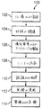
図面をより特定的に参照し、図1に示す、航空機を製造して実際に使用する方法100と、図2に示す航空機200とに関して、この開示の実施例を説明することができる。まず図1を見ると、航空機を製造して実際に使用する方法を示す図が、有利な実施例に従って示される。生産前において、例示的な、航空機を製造して実際に使用する方法100は、図2の航空機200の仕様および設計(102)と、材料の調達(104)とを含み得る。生産中において、図2の航空機200の部品およびサブアセンブリの製造(106)と、システム統合(108)とが行なわれる。その後、図2の航空機は、実際の使用(112)に供されるために、認証および配送(110)を経ることが考えられる。図2の航空機200は、顧客により実際の使用に供される間、日常的な整備および点検(114)のためにスケジュール設定され、この整備および点検(114)は、修正、再構成、改装、および他の整備または点検を含み得る。
With particular reference to the drawings, the embodiments of this disclosure can be described with respect to the
航空機を製造して実際に使用する方法100のプロセスの各々は、システムインテグレータ、第三者、および/またはオペレータにより実施または施行され得る。この例において、オペレータは顧客であり得る。この説明のために、システムインテグレータは、以下のものに限定されないが、任意の数の航空機製造業者および主要システムのサブコントラクタ(下請業者)を含み得、第三者は、以下のものに限定されないが、任意の数の販売業者、下請業者、および供給業者を含み得、オペレータは、航空会社、リース会社、軍部、サービス組織等であり得る。
Each of the processes of
次に図2を参照すると、有利な実施例が実現され得る航空機の図が示される。この例において、航空機200は、図1の、航空機を製造および実際に使用する方法100により生産され、複数のシステム204および内装206とともに機体202を含み得る。システム204の例は、推進力システム208、電気システム210、油圧システム212、および環境システム214の1つ以上を含む。任意の数の他のシステムが含まれてよい。航空宇宙産業の例を示しているが、他の産業、たとえば自動車産業および船舶建造産業に対し、異なる有利な実施例を適用してもよい。
With reference now to FIG. 2, a diagram of an aircraft is depicted in which an advantageous embodiment may be implemented. In this example, the
本明細書で実施する機器および方法は、図1の、航空機を製造して実際に使用する方法100の1つ以上の段階のいずれかにおいて使用され得る。たとえば、図1の、部品およびサブアセンブリの製造(106)で生産される部品またはサブアセンブリは、図1において航空機200が実際の使用(112)に供されている間に修繕または修正される部品またはサブアセンブリと同様の態様で、作製または製造され得る。
The equipment and methods implemented herein may be used in any of one or more stages of the
また、1つ以上の機器の実施例、方法の実施例、またはその組合せは、生産段階中に、たとえば、図1の部品およびサブアセンブリの製造(106)およびシステム統合(108)において、たとえば以下のものに限定されないが、航空機200の組立または航空機200の費用の削減を実質的に促進することにより、利用され得る。同様に、1つ以上の機器の実施例、方法の実施例、またはその組合せは、図1の、航空機200が実際の使用(112)に供される間か、または、図1の整備および点検(114)中に利用され得る。より特定的には、図1の整備および点検(114)中に異なる有利な実施例を使用して、たとえば、複合部品の修繕または修正等の整備作業中に使用するための層レイアップデータを提供することができる。
Also, one or more instrument embodiments, method embodiments, or combinations thereof may be performed during the production phase, such as in part and subassembly manufacturing (106) and system integration (108) of FIG. Although not limited to that, it can be utilized by substantially facilitating the assembly of
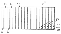
図3は、この開示の有利な実施例の説明を補助する、複合構造の上面図である。複合構造は、参照番号300により示され、一般に、互いの上に形成された複合材料の複数のプライまたは層からなり、各層は、並べて配列された、複数の細片または列の複合材料で形成される。
FIG. 3 is a top view of a composite structure that assists in explaining an advantageous embodiment of the present disclosure. The composite structure is indicated by
より特定的に、図3は、並べて配列された複合材料の複数の列304で形成された複合
構造300の上部層302を示す。図3に示すように、上部層302は、18本の列304で形成される。これは、例示としてのみ意図されるものである。なぜなら、複合構造300の層が、任意の所望のサイズの複合構造を作製するために、任意の所望の数の列で形成され得るためである。
More specifically, FIG. 3 shows an
上に示したように、複合構造300は、複数の層を含み得、各層は、並べて配列された複数の列で形成される。隣接する層の列は、異なる角度で配向され得る。図3は、点線で、第2の層312の一部を示す。この第2の層312は、層302の真下にあり、層302の列304に対して45度で配向された、並んだ列314で形成される。
As indicated above, the
複合構造300等の複合構造は、たとえば以下のものに限定されないが、6つの層からなり得、当該層のうちの2つが横方向に配向された列を有し、2つが当該横方向の列に対して+45度で配向された列を有し、2つが当該横方向の列に対して−45度で配向された列を有する。
A composite structure, such as
列304は、複合樹脂材料を含み得、たとえば以下のものに限定されないが、複数の繊維、たとえば以下のものに限定されないが、カーボン繊維が中に埋込まれたヘラクレス(Hercules)3501−6樹脂を含み得る。以下により詳しく説明するように、列304は、材料配置機械(図3には図示せず)により、一度に1つずつレイアップされ得る。この材料配置機械は、基板上を前後に横切るのに伴い、熱を与えて樹脂材料を軟化させ、かつ、圧縮力を与えて列を基板に付着させる。基板は、レイアップされる第1の層に対するマンドレルまたは他の構造、および、レイアップされる以降の層のための下地層であり得る。
Row 304 may comprise a composite resin material, such as, but not limited to, a plurality of fibers, such as, but not limited to, Hercules 3501-6 resin embedded with carbon fibers therein Can be included. As will be described in more detail below, the
複合構造の層を形成するために列を並べてレイアップするプロセスの間に、さまざまな種類の異物およびゴミ(FOD)が、形成されている層の表面上に蓄積することが考えられる。異物ゴミとしても公知のこのような異物およびゴミは、しばしば、本明細書において単に「異物」と呼ばれ、たとえば以下のものに限定されないが、樹脂ボール、繊維束、および裏打ち材料片を含み得る。 During the process of laying up in a row to form a composite layer, it is possible that various types of foreign matter and debris (FOD) accumulate on the surface of the layer being formed. Such foreign matter and debris, also known as foreign debris, is often referred to herein simply as "foreign matter" and can include, for example, but not limited to, resin balls, fiber bundles, and pieces of backing material .
図4は、この開示の有利な実施例の説明を補助する、複合構造の表面上に蓄積した異物を示す、複合構造の一部の図である。特に、図4は、複合構造400の層402の一部の表面404を示す。層402の例示された部分は、並んだ列406および408の一部を含む。
FIG. 4 is a diagram of a portion of a composite structure showing foreign material accumulating on the surface of the composite structure to assist in explaining an advantageous embodiment of this disclosure. In particular, FIG. 4 shows a
図4はまた、層402の表面404上に蓄積したいくつかの異物も示す。示された異物は、樹脂ボール410、繊維束412、および裏打ち材料のいくつかの破片414を含む。
FIG. 4 also shows some foreign material that has accumulated on the
樹脂ボールは、複合構造を形成するために列がレイアップされるのに伴ない、列を形成する複合樹脂材料が部分的に硬化して付着性を有するようになった結果、生じる。樹脂は、材料配置機械上に集まり、列がレイアップされるのに伴って機械から層上に定期的に落下し、形成されている層の表面上に、樹脂ボール410等の樹脂ボールを形成し得る。樹脂ボールは、たとえば、直径のサイズが約16分の1インチである、ほぼ球形の、相対的に小さな物体を構成し得る。樹脂ボールは一般に、図4に示すように、列の縁端付近または隣接する列の間に蓄積する。
Resin balls arise as a result of the composite resin material forming the rows becoming partially cured and adherent as the rows are laid up to form a composite structure. The resin collects on the material placement machine and periodically drops from the machine onto the layer as the rows are laid up, forming a resin ball such as the
繊維束412は、綿毛ボールとも呼ばれ、列がレイアップされるのに伴って複合樹脂材料から分離した、ほぐれた繊維の蓄積物を含む。繊維束412は、不規則な形状を有する傾向にあり、たとえば約4分の1インチ以上であって、通常、樹脂ボールよりも大きい。
The
たとえばミラー(Mylar)または紙で形成される裏打ち材料片414もまた、材料配置動作中にレイアップされる列の表面上に落下して固着し得る。この材料配置動作中に、列のレイアップ前に除去されなければならない裏打ち材料を含む、連続した長さのテープを担持するスプールから列が配設される。裏打ち材料片414は、規則的な、ほぼ三角形の形状を有する傾向にあり、約2分の1インチから約16分の1インチまでの寸法を有し得る。
A piece of
形成されている複合構造の層の表面上に、樹脂ボール410、繊維束412、および裏打ち材料片414等の異物が存在することは、いくつかの理由により望ましくないことが考えられる。たとえば、異物は、形成されている複合構造の層間に閉じ込められ得、これは望ましいことではない場合がある。また、異物は、複合構造内に塊を形成するおそれがあり、構造の均一性に影響を及ぼす。したがって、層が形成されるのに伴って当該層の表面上に異物が蓄積する際に、当該異物を検出することが望ましい。層が形成されるのに伴って異物を検出することにより、現在形成されている層の上に次の層が形成される前にそれらの異物を除去することができる。
The presence of foreign matter such as
また、検出された各異物の種類を識別して、累積異物指標を求め得ることも望ましい。たとえば以下のものに限定されないが、検出された異物の総数または検出された異物の異なる種類の各々の総数を求め得ることが望ましい。一般に、異物の指標を求めることにより、材料配置機械または材料配置プロセスの全体における問題の認識および是正を助けて、たとえば以下のものに限定されないが、異物の発生数を減らすことができる。 It is also desirable to be able to determine the accumulated foreign matter index by identifying the type of each foreign matter detected. For example, but not limited to the following, it is desirable to be able to determine the total number of detected foreign objects or the total number of each of the different types of detected foreign objects. In general, determining the index of foreign matter helps to recognize and correct problems throughout the material placement machine or material placement process, for example, but not limited to, the number of foreign matter occurrences can be reduced.
図4に示すように、たとえばサイズおよび形状の差異により、異なる種類の異物を互いに視覚的に区別することができるため、この開示の有利な実施例は、異物を検出して分類するため、および、検出した異物の累積記録を提供するための方法およびシステムを提供する。 As shown in FIG. 4, because different types of foreign objects can be visually distinguished from each other, for example by size and shape differences, an advantageous embodiment of this disclosure is for detecting and classifying foreign objects, and A method and system for providing a cumulative record of detected foreign matter is provided.
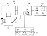
図5は、この開示の有利な実施例に従った複合構造の累積異物指標を求めるためのシステムのブロック図である。このシステムは、参照番号500によって包括的に示され、視覚システム502、照明システム504、プロセッサ506、データ格納ユニット508、およびユーザインターフェイス510を含み得る。
FIG. 5 is a block diagram of a system for determining a composite foreign body index according to an advantageous embodiment of the present disclosure. This system is indicated generally by
視覚システム502は、レイアップされている複合材料512の列に対して配置されて、当該列がレイアップされるのに伴い当該列の連続したセグメントの画像を取込む1つ以上のカメラを含み得る。視覚システム502は、材料配置機械の圧縮ローラのニップのすぐ下流に配置され得、ここで列が加熱され、下地基板、たとえば、形成されている複合構造の下地層に付着させる。
The
照明システム504は、視覚システム502により撮像されている列のセグメントを照明するために位置付けられた1つ以上の光源を含み得る。照明システム504からの光は、セグメント自体の複合材料により反射されるのとは異なる態様で、照明されているセグメント上の異物により反射され、視覚システム502が、セグメント上の異物の視認可能な画像を取込むことを可能にする。
The
この開示の有利な実施例に従い、広範囲のカメラを使用することができる。このようなカメラは、たとえば以下のものに限定されないが、カラーまたは白黒画像を取込むことのできる市販のカメラを含み得る。製造システム502はまた、テレビ受像機か、または、画像センサと、カメラの作動中に光が通過するレンズとを有する他の種類のビデオカメラも含み得る。視覚システム502はまた、赤外線感知カメラ、赤外線透過フィルタ機能を
有する可視光カメラ、光ファイバカメラ、同軸カメラ、電荷結合素子(Charge Coupled Device(CCD))、または相補型金属酸化物センサ(Complementary Metal Oxide Sensor(CMOS))を含み得る。
A wide range of cameras can be used in accordance with the advantageous embodiments of this disclosure. Such cameras may include, for example, but are not limited to, commercially available cameras that can capture color or black and white images.
照明システム504は、同一のまたは異なる種類の1つ以上の光源を含み得る。照明システム504は、たとえば以下のものに限定されないが、1つ以上の赤外線光源、および/または、1つ以上の蛍光源、ストロボ光源、希ガスアーク灯光源、レーザ源、もしくは発光ダイオード(LED)源を含み得る。
The
照明システム504は、炭素等の黒い列材料の検査に役立つ光の赤外線(IR)成分を増大させるパワーレベルで作動させることができる。しかしながら、一般に、照明システムに対する特定のパワーレベルおよび波長は、少なくとも部分的に、視覚システムの速度および感度、列がレイアップされる速度、ならびに、レイアップされている列の材料の反射性に依存し得る。
The
図6は、開示の有利な実施例に従った、視覚システムおよび照明システムが搭載された材料配置機械のヘッドユニットの正面図である。材料配置機械は、参照番号600により包括的に示され、視覚システム602および照明システム604が上に搭載されている。視覚システム602は、図5の視覚システム502として実現され得、照明システム604は、図5の照明システム504として実現され得る。
FIG. 6 is a front view of a head unit of a material placement machine equipped with a vision system and a lighting system according to an advantageous embodiment of the disclosure. The material placement machine is indicated generally by the
図6に示す有利な実施例において、視覚システム602は、2つのカメラ612および614を含む。以下により詳しく説明するように、カメラ612および614は、レイアップされている列が、8インチの幅を有しているときに利用され得、それにより、各カメラが、列の3インチ×8インチのセグメントのうちの、3インチ×4インチの部分の画像を形成するようにする。レイアップされる列が4インチの幅を有し得る開示の有利な実施例では、1つのカメラで十分であり得る。
In the advantageous embodiment shown in FIG. 6,
照明システム604はまた、1対の光源616および618も含み得る。光源616は、4インチ幅の列の3インチ×4インチのセグメント、または、8インチ幅の列の3インチ×8インチのセグメント等の撮像区域を照明する光源であり得る。図6に示す有利な実施例において、区域光源616は、可視光源を含み得る。
The
光源618は、撮像されている列のセグメント上に複数の細いレーザ線を形成する複数の小さな固体レーザを含み得る。この点に関し、異なる光源が、列の表面上の異なる種類の異物の検出および識別を容易にし得ることが分かっている。
The
図7は、作製されている複合構造の表面に対して正しく位置付けられた図6のヘッドユニットの図である。より特定的に、図7は、複合材料の列をレイアップして、参照番号700により包括的に示される複合構造の層を形成するように位置付けられたヘッドユニット620を示す。示すように、図7において、レーザ光源618は、形成されている複合構造の表面に近接して配置されるようにヘッドユニット620上に搭載され、図7で視認することのできない光源616およびカメラ612、614もまた、複合構造の表面付近に搭載される。
FIG. 7 is a diagram of the head unit of FIG. 6 positioned correctly with respect to the surface of the composite structure being fabricated. More specifically, FIG. 7 shows a
図5に戻ると、視覚システム502は、図6および図7に示す材料配置機械600のヘッドユニット620が複合構造を横切って前後に移動するのに伴い、列512の連続したセグメントのリアルタイム画像を取込むように構成される。画像が取込まれるセグメントまたは検査区域は、図6および図7に示すように、機械600の圧縮ローラ622のニップ624のすぐ下流に存在し得る。
Returning to FIG. 5, the
取込まれた画像は、プロセッサ506により直ちに分析および/または処理されるため、メモリユニット508に格納され得る。プロセッサ506は、視覚システム502から直接、または、画像が格納されたメモリユニット508から、画像を受信し得る。プロセッサ506はその後、画像を処理および分析して、画像により捕捉された異物を検出および識別し、検出されかつ識別された異物から、累積異物指標を求めることができる。プロセッサ506およびメモリユニット508は、従来のコンピュータの構成要素であり得る。
The captured image can be stored in the
以下により詳しく説明するように、メモリユニット508は、エラーファイル520、画像処理参照ライブラリ522、およびルックアップテーブル524を含み得、これらは、プロセッサ506により使用されて、画像により捕捉された異物を識別し、累積異物指標を求める。プロセッサ506は、画像処理ソフトウェア526を含み、列の画像上で捕捉された、異なる種類の異物を識別することができる。
As will be described in more detail below, the
ユーザインターフェイス510は、プロセッサ506と通信する。図5に示すように、ユーザインターフェイス510は、以下のものに限定されないが、コンピュータモニタ上に表示画面532を含み得、また、以下のものに限定されないが、カーソルを移動させてユーザによるさまざまなシステムの設定値およびパラメータの入力を可能にするためのキーボードおよび/またはマウス等のユーザ入力部534も含み得る。
表示画面532は、図10に示すウインドウを含み得、このウインドウにおいて、複合構造512のセグメントの画像が、ユーザによる視認用に表示され得る。
システム500はまた、複合構造512上の異物の位置をマーキングするためのマーキング装置514も含み得る。マーキング装置514は、異物の検出時にプロセッサ506により起動され得る。マーキング装置514は、複合構造512上の、異物が検出された区域に、或る量のインク、塗料等を噴射するか、または堆積させることができる。このマーキングにより、異物の位置を容易に識別することができ、当該異物の除去を容易にする。
The
この開示の有利な実施例に従ったシステム500の動作において、視覚システム502は、材料配置機械600(図6および図7)により列がレイアップされるのに伴い、当該列の画像を生成する。各画像は、列の幅に等しい幅、たとえば以下のものに限定されないが、4インチまたは8インチの幅を有し得、各画像は、たとえば以下のものに限定されないが、3インチの同じ高さを有して、検出された異物の位置を確かめるための機構を提供することができる。
In operation of the
プロセッサ506内のソフトウェアは、ユーザインターフェイス510のユーザ入力部534を介してユーザが入力した、予測層数および1層当たりの予測列数に従い、層の数および列の数を、メモリユニット508のエラーログ520内に記録する。材料配置機械600のヘッドユニット620が1つのパスの終了時に複合構造の表面から持上がるたびに、ヘッドユニット620は、列がプロセッサにより識別され得るように、1つの列の終了と、次の列の始まりとを信号で通知する。各画像には、プロセッサ506により連続番号が割当てられ、この番号は、その画像が撮られた列のセグメントの層の数および列の数とともに、エラーファイル520内にログ記録される。
The software in the
図8は、この開示の有利な実施例に従った、列のレイアウトと、複合構造の層を形成する列のセグメントの画像とを示す図である。図8は、画像800として包括的に示される個々の画像を示し、これらの個々の画像は、図8の層1として示される層を形成する列の
セグメントから撮られたものである。列は、列1の下部に対応する画像800−1から列1の上部に対応する画像800−7までレイアップされ、さらに列16の上部に対応する画像800−112で終了する。図4からの異物410、412、または414のうちの1つ以上等の異物が画像800の1つに現われた場合、その寸法属性(たとえば、図9に示す寸法属性902)が図5の画像処理ソフトウェア526によって求められ、画像番号、列番号、および層番号とともに、エラーファイル520に入力される。この画像処理ソフトウェアは、エッジ検出等の標準的な画像処理の手順を使用して、図4における、検出された異物410、412、414の寸法属性902を求めることができる。
FIG. 8 is a diagram illustrating a column layout and an image of column segments forming a composite structure layer, in accordance with an advantageous embodiment of the present disclosure. FIG. 8 shows the individual images shown generically as
たとえば以下のものに限定されないが、検出された異物の長さ、高さ、および形状等の寸法属性902が一旦求められると、これらの寸法属性を、「ブロブ(blob)」のオプションの画像処理参照ライブラリ522およびルックアップテーブル524とともに使用して、検出された異物410、412、414に対し、種類または部類906を割当てる。この同じルックアップテーブル524は、異物410、412、416の各部類または種類906についての最大可能サイズを提供することができ、それに基づいて異物の容認または否認が行なわれる。
For example, but not limited to the following, once the
図9は、図5の複合構造の累積異物指標を求めるためのシステムのプロセッサにおけるエラーファイルのセグメントを概略的に示す図である。特に、図9は、追加された属性902および分類906とともにエラーテーブル520のセグメントを示す。904に図示のとおり、当該ファイルは、均一な幅(x)と設定された画像フレームサイズ(y)とに基づいた異物のx−y位置を記録する。単位面積当たりの累積FODは、既知の寸法情報および検出されたFOD数から抽出され得る。
FIG. 9 is a diagram schematically showing a segment of an error file in the processor of the system for obtaining the cumulative foreign object index of the composite structure of FIG. In particular, FIG. 9 shows a segment of error table 520 with added
図10は、図5の複合構造の累積異物指標を求めるためのシステムにおけるユーザインターフェイスを示す図である。図10に図示のとおり、ユーザインターフェイス520は、実時間で撮像された現在のセグメントまたは検査区域を表示するディスプレイスクリーン532を含む。ユーザ入力部534は、許容基準および画像フレームサイズなどのパラメータを入力および変更するために設けられる。高度に視認可能な赤−緑の「合格/不合格」インジケータ1002が設けられ、図4の異物410、412、414が検出および測定されると実時間で点滅し得る。FODカウンタ1004は、FODについての部類および累積合計により現在合計を提供し得る。
FIG. 10 is a diagram showing a user interface in the system for obtaining the cumulative foreign matter index of the composite structure of FIG. As shown in FIG. 10, the
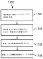
図11は、この開示の有利な実施例に従った複合構造の累積異物指標を求めるための方法を示すフローチャートである。より特定的には、図11は、この開示の有利な実施例に従った、繊維およびテープ配置プロセスによる複合構造の作製中に複合構造上に蓄積した異物についての累積異物指標を求めるための方法を示す。 FIG. 11 is a flowchart illustrating a method for determining a cumulative foreign matter index for a composite structure in accordance with an advantageous embodiment of the present disclosure. More specifically, FIG. 11 illustrates a method for determining a cumulative foreign material index for foreign material accumulated on a composite structure during fabrication of the composite structure by a fiber and tape placement process, according to an advantageous embodiment of the present disclosure. Indicates.
当該方法は、概して参照番号1100によって示されており、複合構造の配置中に複合構造の連続したセグメントの画像を記録することから始まる(ステップ1102)。記録された画像は、複合構造上の異物を検出するために分析され、複合構造上で検出された異物の累積異物指標が求められる(ステップ1106)。次いで、累積異物指標がユーザに提供される(ステップ1108)。
The method is indicated generally by
図12は、この開示のさらなる有利な実施例に従った、複合構造の累積異物指標を求めるための方法を示すフローチャートである。より特定的には、図12は、この開示のさらなる有利な実施例に従った、繊維およびテープ配置プロセスによる複合構造の作製中に複合構造上に蓄積した異物についての累積異物指標を求めるための方法を示す。 FIG. 12 is a flowchart illustrating a method for determining a composite structure cumulative foreign object index in accordance with a further advantageous embodiment of the present disclosure. More specifically, FIG. 12 illustrates a cumulative foreign matter index for foreign matter that has accumulated on a composite structure during fabrication of the composite structure by a fiber and tape placement process, in accordance with a further advantageous embodiment of this disclosure. The method is shown.
当該方法は概して参照番号1200で示されており、ユーザ入力を受信することから始
まる(ステップ1202)。図5においてユーザ入力部534として実現され得るユーザ入力は、作製されるべき複合構造に関する情報と、累積情報の生成時に用いられるべきパラメータに関する情報とを含み得る。たとえば、以下のものに限定されないが、作製されるべき複合構造に関するユーザ入力は、作製されている複合構造の層の数と、当該複合構造の各層の列の数とに関する情報を含み得る。累積情報を生成するためのパラメータに関する情報は、図4における異物410、412および414のうちの1つなどの識別された異物を許容または拒否するための画像フレームサイズおよび許容基準を含み得る。
The method is generally indicated by
入力情報が受信された後、材料配置装置が列をレイアップして、列ごとおよび層ごとに複合構造を作製する(ステップ1204)。列がレイアップされると、当該列の連続したセグメントの画像が実時間で形成される(ステップ1206)。この開示の有利な実施例においては、各々の画像の幅は、たとえば、以下のものに限定されないが、配置されている列の幅に等しくてもよく、当該列に沿った各々の画像の長さは、たとえば、以下のものに限定されないが、同じであってもよい。たとえば、以下のものに限定されないが、配置されている列の幅が4インチである有利な実施例においては、各々の画像の長さは、3インチ×4インチの長方形の連続したセグメントの列からなる画像を形成するために3インチとなり得る。配置されている列の幅が8インチである有利な実施例においては、各々の連続した画像は、1組の並んだ画像部分から形成されてもよく、各々の部分は、3インチ×8インチの連続したセグメントの列からなる画像を形成するように3インチ×4インチの長方形であり得る。 After the input information is received, the material placement device lays up the columns to create a composite structure for each column and layer (step 1204). When a column is laid up, an image of successive segments of that column is formed in real time (step 1206). In an advantageous embodiment of the present disclosure, the width of each image is not limited to, for example, but may be equal to the width of the arranged column and the length of each image along that row. For example, it is not limited to the following, but may be the same. For example, but not limited to the following, in an advantageous embodiment where the width of the arranged rows is 4 inches, the length of each image is a row of rectangular continuous segments of 3 inches by 4 inches. Can be 3 inches to form an image consisting of In an advantageous embodiment in which the arranged rows are 8 inches wide, each successive image may be formed from a set of side-by-side image portions, each portion being 3 inches by 8 inches. It can be a 3 inch by 4 inch rectangle to form an image consisting of a series of consecutive segments.
連続した列セグメントの画像が形成されると、各々の画像がエラーファイルに記録され、これが、画像の識別情報とともに図5におけるエラーファイル520になり得る(ステップ1208)。より特定的には、各々の画像には検査ソフトウェアによって連続した画像番号が割当てられ、加えて、当該ソフトウェアは、ステップ1202においてユーザが入力した情報に従って撮像された列セグメントの層番号と列番号とが記録される。こうして、各々の画像によって表わされる列セグメントが、エラーファイルにおけるその関連する画像とともに識別および記憶される。
As images of successive column segments are formed, each image is recorded in an error file, which can be
次いで、各々の画像を分析して、たとえば、以下のものに限定されないが、画像に対応する列セグメント上の異物410、412または414のうちの1つなどの如何なる異物(FOD:foreign objects)をも検出し、寸法属性、たとえば、以下のものに限定されないが、異物の長さ(ステップ1212)、高さ(ステップ1214)および形状(ステップ1216)が求められ、図9の902に図示のとおり、エラーファイル520に入力される。次いで、求められた属性が、検出された異物の種類または部類を求めるために、ルックアップテーブル524と共に「ブロブ」オプションの画像処理参照ライブラリを用いて分析され、当該部類がまた、図9における906に図示のとおり、エラーファイル520に入力される(ステップ1218)。
Each image is then analyzed for any foreign objects (FOD) such as, but not limited to, one of the
ルックアップテーブル524はまた、不適格なFODをソフトウェアが識別できるように、FODの各々の部類または種類についての最大許容サイズを提供し得る(ステップ1220)。FODが拒否されると、たとえば、図5に示されるユーザインターフェイス510上のインジケータ1002を作動させることによってユーザに通知される(ステップ1222)。インジケータ1002は、異物が検出および測定されると実時間で動作するので、ユーザは、現在形成されている層の上に次の層が加えられる前に、異物を除去するのに適切な措置を講じることができる。
Lookup table 524 may also provide a maximum allowable size for each category or type of FOD so that the software can identify ineligible FODs (step 1220). If the FOD is rejected, the user is notified, for example, by activating an
ソフトウェアはまた、検出および識別されたFODに関する累積情報を生成する(ステップ1224)。この累積情報はまた、たとえば、FODの部類ごとの累積合計(ステップ1226)および/またはすべてのFODについての累積合計(ステップ1228)と
してユーザに提供され得る。このような累積情報は、既知の寸法情報およびFOD識別番号を用いて求められる単位面積当たりの累積FOD情報を含み得るか、または、当該情報は、作製された複合単位当たりの累積FOD情報、または、別の基準に基づいた累積情報を含み得る。
The software also generates cumulative information regarding the detected and identified FOD (step 1224). This cumulative information may also be provided to the user as, for example, a cumulative total for each category of FOD (step 1226) and / or a cumulative total for all FODs (step 1228). Such cumulative information may include cumulative FOD information per unit area determined using known dimensional information and FOD identification numbers, or the information may include cumulative FOD information per composite unit produced, or , May include cumulative information based on other criteria.
さまざまな有利な実施例の説明を、例示および記載の目的で提示してきたが、これは網羅的であることを意図するものではなく、開示された形態の実施例に限定されることを意図するものでもない。多くの変更例および変形例が当業者に明らかになるだろう。さらに、さまざまな有利な実施例は、他の有利な実施例に比べてさまざまな利点を提供し得る。選択された実施例は、実施例および実際の応用例の原理を最も良く説明し、企図された特定の用途に適したさまざまな変更例を含むさまざまな実施例についての開示を他の当業者が理解することを可能にするために選択および記載される。 The description of various advantageous embodiments has been presented for purposes of illustration and description, but is not intended to be exhaustive and is intended to be limited to the embodiments in the form disclosed. Not a thing. Many modifications and variations will be apparent to practitioners skilled in this art. Furthermore, the different advantageous embodiments may provide different advantages over the other advantageous embodiments. The selected embodiments best describe the principles of the embodiments and actual applications, and others skilled in the art will disclose various embodiments including various modifications suitable for the particular application envisioned. Selected and described to allow understanding.
502 視覚システム、504 照明システム、506 プロセッサ、508 データ格納ユニット、510 ユーザインターフェイス 502 visual system, 504 lighting system, 506 processor, 508 data storage unit, 510 user interface
Claims (14)
前記複合構造の配置中に複合構造の連続したセグメントの画像を記録するステップと、
前記複合構造上の異物を検出するために前記記録された画像を分析するステップと、
前記複合構造上で検出された異物の累積異物指標を求めるステップと、
前記累積異物指標をユーザに提供するステップとを含む、方法。 A method for determining a cumulative foreign matter index during fabrication of a composite structure,
Recording images of successive segments of the composite structure during placement of the composite structure;
Analyzing the recorded image to detect foreign matter on the composite structure;
Obtaining a cumulative foreign matter index of foreign matter detected on the composite structure;
Providing the cumulative foreign object index to a user.
前記複合構造上で検出された各々の異物の寸法属性を求めるために各々の記録された画像を分析するステップと、
前記求められた寸法属性から、前記複合構造上で検出された各々の異物の種類を識別するステップとを含む、請求項1に記載の方法。 Analyzing the recorded image to detect foreign matter on the composite structure;
Analyzing each recorded image to determine dimensional attributes of each foreign object detected on the composite structure;
The method according to claim 1, further comprising the step of identifying the type of each foreign object detected on the composite structure from the determined dimensional attributes.
前記複合構造上で検出された各々の異物の長さ、高さおよび形状を求めるために各々の記録された画像を分析するステップを含む、請求項2に記載の方法。 Analyzing each recorded image to determine dimensional attributes of each foreign object detected on the composite structure;
3. The method of claim 2, comprising analyzing each recorded image to determine the length, height and shape of each foreign object detected on the composite structure.
前記複合構造上で検出された異物の累積合計を求めるステップを含む、請求項1から3のいずれかに記載の方法。 The step of obtaining a cumulative foreign matter index of foreign matter detected on the composite structure,
The method according to any one of claims 1 to 3, further comprising a step of obtaining a cumulative total of foreign substances detected on the composite structure.
前記複合構造上で単位面積当たりで検出された異物の累積合計を求めるステップを含む、請求項4に記載の方法。 The step of obtaining the cumulative total of foreign matters detected on the composite structure is as follows:
5. The method of claim 4, comprising determining a cumulative total of foreign objects detected per unit area on the composite structure.
前記複合構造上で検出された各々の種類の異物についての累積合計を求めるステップを含む、請求項2に記載の方法。 The step of obtaining a cumulative foreign matter index of foreign matter detected on the composite structure,
The method of claim 2, comprising determining a cumulative total for each type of foreign object detected on the composite structure.
前記複合構造上で単位面積当たりで検出された各々の種類の異物についての累積合計を求めるステップを含む、請求項6に記載の方法。 The step of obtaining a cumulative total for each type of foreign matter detected on the composite structure,
The method according to claim 6, further comprising the step of determining a cumulative sum for each type of foreign matter detected per unit area on the composite structure.
前記複合構造上で検出された異物の現在数を維持するステップを含む、請求項1から7のいずれかに記載の方法。 The step of obtaining a cumulative foreign matter index of foreign matter detected on the composite structure,
The method according to any of claims 1 to 7, comprising the step of maintaining the current number of foreign bodies detected on the composite structure.
前記複合構造の配置中に複合構造の連続したセグメントの画像を記録するための視覚システムと、
前記複合構造上の異物を検出するために前記記録された画像を分析し、前記複合構造上で検出された異物の累積異物指標を求めるためのプロセッサと、
累積異物指標をユーザに提供するための出力部とを備える、システム。 A system for determining a cumulative foreign matter index during fabrication of a composite structure,
A visual system for recording images of successive segments of the composite structure during placement of the composite structure;
A processor for analyzing the recorded image to detect foreign matter on the composite structure and determining a cumulative foreign matter index of the foreign matter detected on the composite structure;
And an output unit for providing a cumulative foreign object index to a user.
連続したセグメントによって規定された区域を照らすための視認可能な光源と、
連続したセグメントの狭い細片を照らすための複数のレーザ光源とを含む、請求項9に
記載のシステム。 An illumination system, the illumination system comprising:
A visible light source for illuminating an area defined by a continuous segment;
10. A system according to claim 9, comprising a plurality of laser sources for illuminating narrow strips of continuous segments.
Applications Claiming Priority (1)
| Application Number | Priority Date | Filing Date | Title |
|---|---|---|---|
| US11/927,115 US8068659B2 (en) | 2003-12-02 | 2007-10-29 | Method and system for determining cumulative foreign object characteristics during fabrication of a composite structure |
Publications (2)
| Publication Number | Publication Date |
|---|---|
| JP2009109492A true JP2009109492A (en) | 2009-05-21 |
| JP2009109492A5 JP2009109492A5 (en) | 2011-10-13 |
Family
ID=40291050
Family Applications (1)
| Application Number | Title | Priority Date | Filing Date |
|---|---|---|---|
| JP2008270661A Pending JP2009109492A (en) | 2007-10-29 | 2008-10-21 | Method and system for determining cumulative foreign object characteristics during manufacturing of composite structure |
Country Status (3)
| Country | Link |
|---|---|
| US (1) | US8068659B2 (en) |
| EP (1) | EP2056095B1 (en) |
| JP (1) | JP2009109492A (en) |
Cited By (1)
| Publication number | Priority date | Publication date | Assignee | Title |
|---|---|---|---|---|
| KR20150006822A (en) * | 2012-05-15 | 2015-01-19 | 더 보잉 컴파니 | Contamination identification system |
Families Citing this family (16)
| Publication number | Priority date | Publication date | Assignee | Title |
|---|---|---|---|---|
| US8934702B2 (en) | 2003-12-02 | 2015-01-13 | The Boeing Company | System and method for determining cumulative tow gap width |
| US7289656B2 (en) | 2003-12-02 | 2007-10-30 | The Boeing Company | Systems and methods for determining inconsistency characteristics of a composite structure |
| DE102010044175A1 (en) * | 2010-11-19 | 2012-05-24 | Mag Ias Gmbh | Method and production unit for the production of fiber composite components |
| WO2014068572A2 (en) | 2012-11-01 | 2014-05-08 | Israel Aerospace Industries Ltd. | Manufacture of integrated structures formed of composite materials |
| US8983171B2 (en) | 2012-12-26 | 2015-03-17 | Israel Aerospace Industries Ltd. | System and method for inspecting structures formed of composite materials during the fabrication thereof |
| US9595092B2 (en) * | 2013-05-10 | 2017-03-14 | The Boeing Company | Methods and systems for inspection of composite irregularities |
| US9595096B2 (en) | 2014-03-10 | 2017-03-14 | The Boeing Company | Composite inspection and structural check of multiple layers |
| GB2528963B (en) | 2014-08-07 | 2018-07-25 | Artform Int Ltd | Product display shelf, system and method |
| US9645095B2 (en) | 2014-10-06 | 2017-05-09 | The Boeing Company | System and method for inspecting a composite part during manufacture |
| US10668673B2 (en) | 2015-05-18 | 2020-06-02 | Flightware, Inc. | Systems and methods for automated composite layup quality assurance |
| US9618459B2 (en) | 2015-05-18 | 2017-04-11 | Flightware, Inc. | Systems and methods for automated composite layup quality assurance |
| US10702076B2 (en) | 2016-01-18 | 2020-07-07 | Atlas Bolt & Screw Company Llc | Sensors, devices, adapters and mating structures for merchandisers and related methods |
| US10588427B2 (en) | 2016-03-23 | 2020-03-17 | Retail Space Solutions Llc | Low product indicator for self facing merchandiser and related methods |
| US10952548B2 (en) | 2016-10-18 | 2021-03-23 | Retail Space Solutions Llc | Illuminated merchandiser, retrofit kit and related methods |
| US10661512B2 (en) | 2017-04-25 | 2020-05-26 | The Boeing Company | Measurement of ply boundaries |
| US10737446B2 (en) | 2017-04-28 | 2020-08-11 | The Boeing Company | Process control of a composite fabrication process |
Citations (15)
| Publication number | Priority date | Publication date | Assignee | Title |
|---|---|---|---|---|
| JPH03108735A (en) * | 1989-09-22 | 1991-05-08 | Hitachi Ltd | Method and apparatus for comparison inspection |
| JP2001110867A (en) * | 1999-10-07 | 2001-04-20 | Hitachi Ltd | Manufacture of electronic device and quality control system for electronic device |
| JP2002057195A (en) * | 2000-08-15 | 2002-02-22 | Hitachi Ltd | Method for preparing data for defect analysis in examination of electronic device and system for analyzing examination data for electronic device |
| JP2002257533A (en) * | 2001-03-01 | 2002-09-11 | Hitachi Ltd | Defect inspection device and its method |
| JP2003077972A (en) * | 2001-09-04 | 2003-03-14 | Hitachi Ltd | Manufacturing method of semiconductor device |
| JP2004111674A (en) * | 2002-09-19 | 2004-04-08 | Toshiba Corp | Method and apparatus for removing foreign matter |
| JP2004286532A (en) * | 2003-03-20 | 2004-10-14 | Olympus Corp | Device and method for visual inspection |
| JP2005049344A (en) * | 2003-07-28 | 2005-02-24 | Boeing Co:The | System and method for identifying defect, foreign matter and debris when manufacturing composite structure |
| US20050117793A1 (en) * | 2003-12-02 | 2005-06-02 | Engelbart Roger W. | Systems and methods for determining defect characteristics of a composite structure |
| JP2005236094A (en) * | 2004-02-20 | 2005-09-02 | Renesas Technology Corp | Method for manufacturing semiconductor device, method and system for failure analysis |
| JP2005262881A (en) * | 2004-03-12 | 2005-09-29 | Boeing Co:The | Method and program enabling automatic repair of defect by material stationing machine |
| US20060109454A1 (en) * | 2004-11-24 | 2006-05-25 | The Boeing Company | In-process vision detection of flaw and fod characteristics |
| WO2007078408A2 (en) * | 2005-10-31 | 2007-07-12 | The Boeing Company | Apparatus and methods for inspecting a composite structure for defects |
| JP2007256119A (en) * | 2006-03-23 | 2007-10-04 | Fujitsu Ltd | Inspection device, lamination apparatus and inspection method |
| JP2007273581A (en) * | 2006-03-30 | 2007-10-18 | Toray Eng Co Ltd | Method and device for inspecting semiconductor wafer |
Family Cites Families (17)
| Publication number | Priority date | Publication date | Assignee | Title |
|---|---|---|---|---|
| US4223346A (en) * | 1979-04-05 | 1980-09-16 | Armco Inc. | Automatic defect detecting inspection apparatus |
| JPS6333160Y2 (en) * | 1980-09-27 | 1988-09-05 | ||
| US5963660A (en) * | 1996-09-26 | 1999-10-05 | The Boeing Company | Method and apparatus for detecting and measuring laps and gaps in composite materials |
| US6064429A (en) * | 1997-08-18 | 2000-05-16 | Mcdonnell Douglas Corporation | Foreign object video detection and alert system and method |
| US7171033B2 (en) * | 2001-03-28 | 2007-01-30 | The Boeing Company | System and method for identifying defects in a composite structure |
| US20020176617A1 (en) * | 2001-05-22 | 2002-11-28 | Pti Advanced Filtration, Inc. | System and method for continuous integrity testing of a material web |
| US6799619B2 (en) * | 2002-02-06 | 2004-10-05 | The Boeing Company | Composite material collation machine and associated method for high rate collation of composite materials |
| US6871684B2 (en) * | 2002-08-13 | 2005-03-29 | The Boeing Company | System for identifying defects in a composite structure |
| US7197177B2 (en) * | 2003-08-29 | 2007-03-27 | Lowe Elvin P | Automated laminate inspection method |
| US7193696B2 (en) * | 2004-04-12 | 2007-03-20 | United Technologies Corporation | Systems and methods for using light to indicate defect locations on a composite structure |
| US20060108048A1 (en) * | 2004-11-24 | 2006-05-25 | The Boeing Company | In-process vision detection of flaws and fod by back field illumination |
| US7889907B2 (en) * | 2005-01-12 | 2011-02-15 | The Boeing Company | Apparatus and methods for inspecting tape lamination |
| US7513964B2 (en) * | 2005-02-28 | 2009-04-07 | The Boeing Company | Real-time infrared thermography inspection and control for automated composite marterial layup |
| US8668793B2 (en) * | 2005-08-11 | 2014-03-11 | The Boeing Company | Systems and methods for in-process vision inspection for automated machines |
| US7435947B2 (en) * | 2005-10-31 | 2008-10-14 | The Boeing Company | Apparatus and methods for integrating encoding functions in material placement machines |
| US7835567B2 (en) * | 2006-01-24 | 2010-11-16 | Ingersoll Machine Tools, Inc. | Visual fiber placement inspection |
| US7362437B2 (en) * | 2006-03-28 | 2008-04-22 | The Boeing Company | Vision inspection system device and method |
-
2007
- 2007-10-29 US US11/927,115 patent/US8068659B2/en not_active Expired - Fee Related
-
2008
- 2008-10-21 JP JP2008270661A patent/JP2009109492A/en active Pending
- 2008-10-23 EP EP08253449.6A patent/EP2056095B1/en not_active Not-in-force
Patent Citations (17)
| Publication number | Priority date | Publication date | Assignee | Title |
|---|---|---|---|---|
| JPH03108735A (en) * | 1989-09-22 | 1991-05-08 | Hitachi Ltd | Method and apparatus for comparison inspection |
| JP2001110867A (en) * | 1999-10-07 | 2001-04-20 | Hitachi Ltd | Manufacture of electronic device and quality control system for electronic device |
| JP2002057195A (en) * | 2000-08-15 | 2002-02-22 | Hitachi Ltd | Method for preparing data for defect analysis in examination of electronic device and system for analyzing examination data for electronic device |
| JP2002257533A (en) * | 2001-03-01 | 2002-09-11 | Hitachi Ltd | Defect inspection device and its method |
| JP2003077972A (en) * | 2001-09-04 | 2003-03-14 | Hitachi Ltd | Manufacturing method of semiconductor device |
| JP2004111674A (en) * | 2002-09-19 | 2004-04-08 | Toshiba Corp | Method and apparatus for removing foreign matter |
| JP2004286532A (en) * | 2003-03-20 | 2004-10-14 | Olympus Corp | Device and method for visual inspection |
| JP2005049344A (en) * | 2003-07-28 | 2005-02-24 | Boeing Co:The | System and method for identifying defect, foreign matter and debris when manufacturing composite structure |
| US20050117793A1 (en) * | 2003-12-02 | 2005-06-02 | Engelbart Roger W. | Systems and methods for determining defect characteristics of a composite structure |
| JP2007513350A (en) * | 2003-12-02 | 2007-05-24 | ザ・ボーイング・カンパニー | System and method for measuring defect properties of composite structures |
| JP2005236094A (en) * | 2004-02-20 | 2005-09-02 | Renesas Technology Corp | Method for manufacturing semiconductor device, method and system for failure analysis |
| JP2005262881A (en) * | 2004-03-12 | 2005-09-29 | Boeing Co:The | Method and program enabling automatic repair of defect by material stationing machine |
| US20060109454A1 (en) * | 2004-11-24 | 2006-05-25 | The Boeing Company | In-process vision detection of flaw and fod characteristics |
| WO2007078408A2 (en) * | 2005-10-31 | 2007-07-12 | The Boeing Company | Apparatus and methods for inspecting a composite structure for defects |
| JP2009513984A (en) * | 2005-10-31 | 2009-04-02 | ザ・ボーイング・カンパニー | Apparatus and method for inspecting a composite structure for defects |
| JP2007256119A (en) * | 2006-03-23 | 2007-10-04 | Fujitsu Ltd | Inspection device, lamination apparatus and inspection method |
| JP2007273581A (en) * | 2006-03-30 | 2007-10-18 | Toray Eng Co Ltd | Method and device for inspecting semiconductor wafer |
Cited By (5)
| Publication number | Priority date | Publication date | Assignee | Title |
|---|---|---|---|---|
| KR20150006822A (en) * | 2012-05-15 | 2015-01-19 | 더 보잉 컴파니 | Contamination identification system |
| JP2015519568A (en) * | 2012-05-15 | 2015-07-09 | ザ・ボーイング・カンパニーTheBoeing Company | Pollution identification system |
| RU2629881C2 (en) * | 2012-05-15 | 2017-09-04 | Зе Боинг Компани | System of identification of pollutants |
| JP2017203781A (en) * | 2012-05-15 | 2017-11-16 | ザ・ボーイング・カンパニーThe Boeing Company | Contamination identification system |
| KR102004571B1 (en) * | 2012-05-15 | 2019-10-01 | 더 보잉 컴파니 | Contamination identification system |
Also Published As
| Publication number | Publication date |
|---|---|
| EP2056095A1 (en) | 2009-05-06 |
| EP2056095B1 (en) | 2018-06-06 |
| US8068659B2 (en) | 2011-11-29 |
| US20090148030A1 (en) | 2009-06-11 |
Similar Documents
| Publication | Publication Date | Title |
|---|---|---|
| US8068659B2 (en) | Method and system for determining cumulative foreign object characteristics during fabrication of a composite structure | |
| US7769224B2 (en) | Systems and methods for determining inconsistency characteristics of a composite structure | |
| JP5274008B2 (en) | System and method for using light to indicate defect locations in composite buildings | |
| CA2468126C (en) | Systems and methods for identifying foreign objects and debris (fod) and inconsistencies during fabrication of a composite structure | |
| US7171033B2 (en) | System and method for identifying defects in a composite structure | |
| US7039485B2 (en) | Systems and methods enabling automated return to and/or repair of defects with a material placement machine | |
| US6871684B2 (en) | System for identifying defects in a composite structure | |
| JP5738515B2 (en) | System and method for determining cumulative tow gap width | |
| CN105487486A (en) | System and method for inspecting a composite part during manufacture |
Legal Events
| Date | Code | Title | Description |
|---|---|---|---|
| RD03 | Notification of appointment of power of attorney |
Free format text: JAPANESE INTERMEDIATE CODE: A7423 Effective date: 20091111 |
|
| A521 | Written amendment |
Free format text: JAPANESE INTERMEDIATE CODE: A821 Effective date: 20100303 |
|
| RD04 | Notification of resignation of power of attorney |
Free format text: JAPANESE INTERMEDIATE CODE: A7424 Effective date: 20100303 |
|
| A521 | Written amendment |
Free format text: JAPANESE INTERMEDIATE CODE: A523 Effective date: 20110826 |
|
| A621 | Written request for application examination |
Free format text: JAPANESE INTERMEDIATE CODE: A621 Effective date: 20110826 |
|
| A977 | Report on retrieval |
Free format text: JAPANESE INTERMEDIATE CODE: A971007 Effective date: 20130208 |
|
| A131 | Notification of reasons for refusal |
Free format text: JAPANESE INTERMEDIATE CODE: A131 Effective date: 20130219 |
|
| A521 | Written amendment |
Free format text: JAPANESE INTERMEDIATE CODE: A523 Effective date: 20130515 |
|
| A131 | Notification of reasons for refusal |
Free format text: JAPANESE INTERMEDIATE CODE: A131 Effective date: 20140311 |
|
| A521 | Written amendment |
Free format text: JAPANESE INTERMEDIATE CODE: A523 Effective date: 20140610 |
|
| A02 | Decision of refusal |
Free format text: JAPANESE INTERMEDIATE CODE: A02 Effective date: 20150106 |