JP2009102995A - Failure diagnostic device for exhaust emission control device - Google Patents
Failure diagnostic device for exhaust emission control device Download PDFInfo
- Publication number
- JP2009102995A JP2009102995A JP2007273003A JP2007273003A JP2009102995A JP 2009102995 A JP2009102995 A JP 2009102995A JP 2007273003 A JP2007273003 A JP 2007273003A JP 2007273003 A JP2007273003 A JP 2007273003A JP 2009102995 A JP2009102995 A JP 2009102995A
- Authority
- JP
- Japan
- Prior art keywords
- nox catalyst
- selective reduction
- reduction type
- upstream
- moisture concentration
- Prior art date
- Legal status (The legal status is an assumption and is not a legal conclusion. Google has not performed a legal analysis and makes no representation as to the accuracy of the status listed.)
- Pending
Links
Images


Abstract
Description
本発明は、内燃機関の排気ガス浄化システムの故障診断装置、特に選択還元型NOx触媒を備える排気ガス浄化システムの故障診断装置に関する。 The present invention relates to a failure diagnosis device for an exhaust gas purification system of an internal combustion engine, and more particularly to a failure diagnosis device for an exhaust gas purification system including a selective reduction type NOx catalyst.
一般に、ディーゼルエンジン等の内燃機関の排気系に配置される排気浄化装置として、酸素共存下でも選択的にNOxを還元剤と反応させる性質を備えた選択還元型NOx触媒が知られている。これは、選択還元型NOx触媒の上流側に必要量の還元剤を添加して、該還元剤を触媒上にて排出ガス中のNOx(窒素酸化物)と還元反応させ、これによりNOxの排出濃度を低減し得るようにしたものである。 In general, as an exhaust purification device disposed in an exhaust system of an internal combustion engine such as a diesel engine, a selective reduction type NOx catalyst having a property of selectively reacting NOx with a reducing agent even in the presence of oxygen is known. This is because a necessary amount of reducing agent is added upstream of the selective reduction type NOx catalyst, and the reducing agent is subjected to a reduction reaction with NOx (nitrogen oxide) in the exhaust gas on the catalyst, thereby discharging NOx. The concentration can be reduced.
そして、自動車の場合には、還元剤としてのアンモニアそのものを搭載して走行することに関して安全確保が困難であることから、毒性のない尿素水を還元剤として使用することが提案されている。即ち、尿素水を選択還元型NOx触媒の上流側で排出ガス中に添加すれば、該尿素水が排出ガス中でアンモニアと炭酸ガスに熱分解され、排出ガス中のNOxが選択還元型NOx触媒上でアンモニアにより良好に還元浄化されるからである。 In the case of automobiles, it is difficult to ensure safety with respect to traveling with ammonia itself as a reducing agent, and therefore it has been proposed to use non-toxic urea water as a reducing agent. That is, if urea water is added to the exhaust gas upstream of the selective reduction type NOx catalyst, the urea water is thermally decomposed into ammonia and carbon dioxide gas in the exhaust gas, and the NOx in the exhaust gas is converted into the selective reduction type NOx catalyst. This is because ammonia is reduced and purified well by ammonia.
ところで、このような尿素水を還元剤としてNOxを還元浄化するようにした排気浄化装置にあっては、熱や排ガス成分により選択還元型NOx触媒が経時的に劣化して、NOx低減性能が徐々に低下してくるため、選択還元型NOx触媒の初期性能を基準としたまま尿素水の添加量制御を継続していると、運転時間が長くなるにつれて、添加した尿素水に余剰分が生じてしまい、NOxの還元浄化反応に使用されないまま選択還元型NOx触媒の後方へ擦り抜けてしまうアンモニアが生じる虞れがあることから、この対策として、選択還元型NOx触媒の前後で排出ガス中のNOx濃度をNOxセンサにより検出して、尿素水の添加量に見合う適切なNOx低減率が得られているかどうかを監視し、必要な量の尿素水を添加しているにもかかわらず適切なNOx低減率が得られない場合に、選択還元型NOx触媒に経時劣化が生じているものと判断する技術が提案されている(例えば、特許文献1参照)。 By the way, in such an exhaust purification device that reduces and purifies NOx using urea water as a reducing agent, the selective reduction type NOx catalyst is deteriorated with time due to heat and exhaust gas components, and the NOx reduction performance gradually increases. Therefore, if the addition amount control of the urea water is continued with the initial performance of the selective reduction type NOx catalyst as a reference, an excess amount is generated in the added urea water as the operation time becomes longer. Therefore, there is a possibility that ammonia may be scrubbed to the rear of the selective reduction type NOx catalyst without being used for the reduction and purification reaction of NOx. As a countermeasure, NOx in the exhaust gas before and after the selective reduction type NOx catalyst is used. The concentration is detected by a NOx sensor, and it is monitored whether an appropriate NOx reduction rate corresponding to the amount of urea water added is obtained, and the necessary amount of urea water is added. If the painful NOx reduction ratio can not be obtained, a technique determines that the deterioration with time occurs in the NOx selective reduction catalyst has been proposed (e.g., see Patent Document 1).
ところで、選択還元型NOx触媒の前後で排出ガス中のNOx濃度が予想通りに低下しない現象は、必ずしも選択還元型NOx触媒の長期使用による経時劣化だけに依存するものではなく、そのNOx濃度の検出時点における排気温度(触媒活性に影響)などにも大きく依存しているため、選択還元型NOx触媒の前後で排出ガス中のNOx濃度が予想通りに低下しないからといって、それが選択還元型NOx触媒の経時劣化によるものとは一概に決めつけられない面があり、また、NOxセンサの応答性や出力特性などにもバラツキがあるため、精度の高いNOx濃度の検出が困難である。 By the way, the phenomenon in which the NOx concentration in the exhaust gas does not decrease as expected before and after the selective reduction type NOx catalyst does not necessarily depend only on the deterioration over time due to the long-term use of the selective reduction type NOx catalyst. Because it also depends greatly on the exhaust temperature (influence on catalyst activity) at the time, the NOx concentration in the exhaust gas does not decrease as expected before and after the selective reduction type NOx catalyst. It is difficult to determine the NOx concentration with high accuracy because there are aspects that cannot be generally determined due to the deterioration of the NOx catalyst over time, and there are variations in the response and output characteristics of the NOx sensor.
そこで、選択還元型NOx触媒の入側に排出ガスの温度を検出する温度センサを備えると共に、該温度センサからの検出信号に基づき排出ガスが所定温度以上となっている時の運転時間を積算して選択還元型NOx触媒の経時劣化の度合を推定する技術が、特許文献2に開示されている。 Therefore, a temperature sensor for detecting the temperature of the exhaust gas is provided on the inlet side of the selective reduction type NOx catalyst, and the operation time when the exhaust gas is higher than the predetermined temperature is integrated based on the detection signal from the temperature sensor. Patent Document 2 discloses a technique for estimating the degree of deterioration with time of a selective reduction type NOx catalyst.
ところで、特許文献1に記載のNOxセンサのみを用いるものは、上述のように、NOxセンサの出力特性のバラツキなどに起因して精度の高いNOx濃度の検出が困難であり、また、特許文献2に開示されている、排出ガスが所定温度以上となっている時の運転時間を積算して選択還元型NOx触媒の経時劣化の度合を推定する技術でも、自動車に搭載された選択還元型NOx触媒の交換時期等を決定するための診断のような場合には、上述のような所定の運転時間の積算のみでその診断を正確に行うことは困難である。 By the way, as described above, the one using only the NOx sensor described in Patent Document 1 is difficult to detect the NOx concentration with high accuracy due to variations in the output characteristics of the NOx sensor. The selective reduction type NOx catalyst mounted on an automobile is also disclosed in the technology for estimating the degree of deterioration over time of the selective reduction type NOx catalyst by integrating the operation time when the exhaust gas is above a predetermined temperature. In the case of a diagnosis for determining the replacement time or the like, it is difficult to accurately perform the diagnosis only by integrating the predetermined operation time as described above.
そこで、本発明の目的は、より正確に選択還元型NOx触媒の劣化診断を行うことができる選択還元型NOx触媒の異常診断装置を提供することにある。 Accordingly, an object of the present invention is to provide an abnormality diagnosis device for a selective reduction NOx catalyst that can more accurately diagnose deterioration of the selective reduction NOx catalyst.
上記目的を達成するための本発明に係る排気ガス浄化システムの故障診断装置の一形態は、内燃機関の排気通路に設けられた選択還元型NOx触媒と、該選択還元型NOx触媒の上流の排気通路に尿素水を供給する尿素水供給手段とを有する排気ガス浄化システムにおいて、前記選択還元型NOx触媒の上流側及び下流側の水分濃度をそれぞれ取得する上流側及び下流側の水分濃度取得手段と、前記上流側及び下流側の水分濃度取得手段によってそれぞれ取得された水分濃度値に基づき、前記選択還元型NOx触媒の正常又は異常を診断する診断手段と、を備えたことを特徴とする。 In order to achieve the above object, one embodiment of a failure diagnosis apparatus for an exhaust gas purification system according to the present invention is a selective reduction type NOx catalyst provided in an exhaust passage of an internal combustion engine, and exhaust gas upstream of the selective reduction type NOx catalyst. In an exhaust gas purification system having urea water supply means for supplying urea water to the passage, upstream and downstream moisture concentration acquisition means for acquiring the upstream and downstream moisture concentrations of the selective reduction type NOx catalyst, respectively And diagnosing means for diagnosing normality or abnormality of the selective reduction type NOx catalyst based on moisture concentration values respectively acquired by the upstream and downstream moisture concentration acquiring means.
上記一形態によれば、排気通路に設けられた選択還元型NOx触媒の上流側及びその下流側の排気通路内の水分濃度が水分濃度取得手段によってそれぞれ取得される。すなわち、選択還元型NOx触媒の上流側においては、吸気からの大気中水分、内燃機関における燃焼により生ずる反応水分、及び尿素水供給手段により供給された尿素水中の水分による排気ガス中の水分濃度が取得される一方、選択還元型NOx触媒の下流側においては、アンモニアによりNOxが還元されることにより発生する水分が加えられた排気ガス中の水分濃度が取得される。この選択還元型NOx触媒上で発生する水分の量は、選択還元型NOx触媒においてNOxの還元反応に使用されたアンモニアの量、換言すると、NOx処理量、延いては、選択還元型NOx触媒の触媒能に比例する。そこで、診断手段により、上流側及び下流側の水分濃度取得手段によってそれぞれ取得された水分濃度値に基づいて、すなわち、上流側の水分濃度値と下流側の水分濃度値とによって、水分濃度の変化量が求められ、この変化量が予め求められていた基準値と比較されて選択還元型NOx触媒の正常又は異常が診断される。したがって、この形態によれば、外部からの特別な操作を必要とすることなく、換言すると、NOx触媒の活性度が高いのに敢えてNOx浄化能が低い状態を作り出すなどの排気エミッションを敢えて悪化させることなく、通常のNOx処理過程で単に水分濃度の変化に基づき選択還元型NOx触媒の正確な正常又は異常の診断を行うことができる。 According to the above aspect, the moisture concentration in the exhaust passage on the upstream side and the downstream side of the selective reduction type NOx catalyst provided in the exhaust passage is respectively acquired by the moisture concentration acquisition means. That is, on the upstream side of the selective reduction type NOx catalyst, the moisture concentration in the exhaust gas due to the atmospheric moisture from the intake air, the reactive moisture generated by combustion in the internal combustion engine, and the moisture in the urea water supplied by the urea water supply means is On the other hand, on the downstream side of the selective reduction type NOx catalyst, the moisture concentration in the exhaust gas to which moisture generated by NOx reduction by ammonia is added is obtained. The amount of moisture generated on the selective reduction type NOx catalyst is the amount of ammonia used in the reduction reaction of NOx in the selective reduction type NOx catalyst, in other words, the amount of NOx treated, that is, the selective reduction type NOx catalyst. It is proportional to the catalytic ability. Therefore, based on the moisture concentration values respectively acquired by the upstream and downstream moisture concentration acquisition means by the diagnostic means, that is, depending on the upstream moisture concentration value and the downstream moisture concentration value, the change in moisture concentration The amount is obtained, and the amount of change is compared with a reference value obtained in advance to diagnose normality or abnormality of the selective reduction type NOx catalyst. Therefore, according to this embodiment, no special operation from the outside is required. In other words, the exhaust emission is intentionally deteriorated, for example, a state in which the NOx catalyst is highly active but the NOx purification ability is low. Therefore, an accurate normal or abnormal diagnosis of the selective reduction type NOx catalyst can be performed simply based on a change in the water concentration in the normal NOx treatment process.
ここで、上記一形態の排気ガス浄化システムの故障診断装置において、前記上流側及び下流側の水分濃度取得手段は、排気通路に設けられ、該選択還元型NOx触媒の上流側及びその下流側の排気通路内の水分濃度をそれぞれ計測する水分濃度計測手段を含み、前記選択還元型NOx触媒の上流側の水分濃度計測手段は、前記尿素水供給手段の下流に設けられていてもよい。 Here, in the failure diagnosis apparatus for an exhaust gas purification system according to the one aspect, the upstream and downstream moisture concentration acquisition means are provided in an exhaust passage, and are provided upstream and downstream of the selective reduction type NOx catalyst. Water concentration measuring means for measuring the water concentration in the exhaust passage may be included, and the moisture concentration measuring means on the upstream side of the selective reduction type NOx catalyst may be provided downstream of the urea water supply means.
この形態によれば、選択還元型NOx触媒の上流側及びその下流側のいずれにおいても、それぞれの水分濃度が水分濃度計測手段により計測される。そして、選択還元型NOx触媒の上流側の水分濃度計測手段が尿素水供給手段の下流に設けられていることから、尿素水供給手段により供給された尿素水中の水分による排気ガス中の水分濃度をも含めて水分濃度計測手段により計測できるので簡単に水分濃度を把握することができる。 According to this embodiment, the moisture concentration is measured by the moisture concentration measuring means on both the upstream side and the downstream side of the selective reduction type NOx catalyst. Since the moisture concentration measuring means on the upstream side of the selective reduction type NOx catalyst is provided downstream of the urea water supply means, the moisture concentration in the exhaust gas due to the water in the urea water supplied by the urea water supply means is determined. Since it can be measured by the moisture concentration measuring means, the moisture concentration can be easily grasped.
また、上記一形態の排気ガス浄化システムの故障診断装置において、前記上流側及び下流側の水分濃度取得手段は、排気通路に設けられ、該選択還元型NOx触媒の上流側及びその下流側の排気通路内の水分濃度をそれぞれ計測する水分濃度計測手段を含み、前記選択還元型NOx触媒の上流側の水分濃度計測手段は、前記尿素水供給手段の上流に設けられていてもよい。 Further, in the failure diagnosis apparatus for an exhaust gas purification system according to the above aspect, the upstream and downstream moisture concentration acquisition means are provided in an exhaust passage, and the upstream and downstream exhaust of the selective reduction type NOx catalyst. Water concentration measuring means for measuring the water concentration in the passage may be included, and the water concentration measuring means upstream of the selective reduction type NOx catalyst may be provided upstream of the urea water supply means.
この形態によれば、選択還元型NOx触媒の上流側及びその下流側のいずれにおいても、それぞれの水分濃度が水分濃度取得手段により取得される。そして、選択還元型NOx触媒の上流側の水分濃度計測手段が尿素水供給手段の上流に設けられていることから、水分濃度計測手段が尿素水供給手段により供給された尿素水の水分付着や噴霧の分布むらなどによる影響を受けることがない。 According to this aspect, the moisture concentration is acquired by the moisture concentration acquisition means on both the upstream side and the downstream side of the selective reduction type NOx catalyst. Since the moisture concentration measuring means on the upstream side of the selective reduction type NOx catalyst is provided upstream of the urea water supply means, the moisture concentration measuring means adheres and sprays the urea water supplied by the urea water supply means. It is not affected by the distribution unevenness.
以下、添付図面を参照して、本発明を実施するための最良の形態を説明する。 The best mode for carrying out the present invention will be described below with reference to the accompanying drawings.
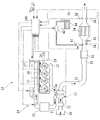
図1は、本発明の実施形態に係る内燃機関の概略的なシステム図である。図中、10は、自動車用の圧縮着火式内燃機関即ちディーゼルエンジンであり、11は吸気ポートに連通されている吸気マニフォルド、12は排気ポートに連通されている排気マニフォルド、13は燃焼室である。本実施形態では、不図示の燃料タンクから高圧ポンプ17に供給された燃料が、高圧ポンプ17によりコモンレール18に圧送されて高圧状態で蓄圧され、このコモンレール18内の高圧燃料がインジェクタ14から燃焼室13内に直接噴射供給される。エンジン10からの排気ガスは、排気マニフォルド12からターボチャージャ19を経た後にその下流の排気通路15に流され、後述のように浄化処理された後、大気に排出される。なお、ディーゼルエンジンの形態としてはこのようなコモンレール式燃料噴射装置を備えたものに限らない。またEGR装置などの他の排気浄化デバイスを含むことも任意である。
FIG. 1 is a schematic system diagram of an internal combustion engine according to an embodiment of the present invention. In the figure, 10 is a compression ignition type internal combustion engine or diesel engine for automobiles, 11 is an intake manifold communicated with an intake port, 12 is an exhaust manifold communicated with an exhaust port, and 13 is a combustion chamber. . In the present embodiment, fuel supplied from a fuel tank (not shown) to the high pressure pump 17 is pumped to the
他方、エアクリーナ20から吸気通路21内に導入された吸入空気は、エアフローメータ22、ターボチャージャ19、インタークーラ23、スロットルバルブ24を順に通過して吸気マニフォルド11に至る。エアフローメータ22は吸入空気量を検出するためのセンサであり、具体的には吸入空気の流量に応じた信号を出力する。スロットルバルブ24には電子制御式のものが採用されている。
On the other hand, the intake air introduced from the
排気通路15には、上流側から順に排気ガス中に含まれる未燃成分を酸化処理する酸化触媒30、微粒子(PM)を捕捉して処理するDPF触媒32及びその通路内の排気ガス中に含まれるNOxを還元して浄化するNOx触媒34が設けられている。本実施形態のNOx触媒34は選択還元型NOx触媒であり、還元剤が添加されたときにNOxを連続的に還元して浄化し得る。
The
DPF触媒32の下流で選択還元型NOx触媒34の上流側の排気通路15には、選択還元型NOx触媒34に還元剤としての尿素を選択的に添加するための添加弁40が設けられている。尿素は尿素水溶液の形で使用され、添加弁40から下流側の選択還元型NOx触媒34に向かって排気通路15内に噴射供給される。添加弁40には、これに尿素水溶液を供給するための供給装置42が接続され、供給装置42には尿素水溶液を貯留するタンク44が接続されている。
An
また、エンジン全体の制御を司る制御手段としての電子制御ユニット(以下ECUと称
す)100が設けられている。ECUl00は,デジタルコンピュータからなり、双方向バスによって相互に接続されたROM(リードオンリメモリ)、RAM(ランダムアクセスメモリ)、CPU(セントラルプロセッサユニット)、入力ポート、出力ポートおよび記憶装置等を含むものである。ECU100は、各種センサ類の検出値等に基づいて、所望のエンジン制御が実行されるように、インジェクタ14、高圧ポンプ17、スロットルバルブ24等を制御する。またECU100は、尿素添加量を制御すべく、添加弁40及び供給装置42を制御する。また、ECUl00は、ROMに格納されたプログラムを実行することによって、後述する故障診断処理をも実行することが可能に構成されており、本発明に係る排気ガス浄化システムの故障診断装置の一例としても機能するように構成されている。
Further, an electronic control unit (hereinafter referred to as ECU) 100 is provided as a control means for controlling the entire engine. The ECU 100 includes a digital computer and includes a ROM (Read Only Memory), a RAM (Random Access Memory), a CPU (Central Processor Unit), an input port, an output port, a storage device, and the like that are connected to each other via a bidirectional bus. . The ECU 100 controls the
ECU100に接続されるセンサ類としては、前述のエアフローメータ22の他、本実施の形態では添加弁40の下流側であって選択還元型NOx触媒34の上流側に設けられた触媒前水分濃度センサ50と選択還元型NOx触媒34の下流側に設けられた触媒後水分濃度センサ52、及び、同じく添加弁40の下流側であって選択還元型NOx触媒34の上流側と下流側にそれぞれ触媒前水分濃度センサ50及び触媒後水分濃度センサ52に近接して設けられた触媒前排気温センサ54及び触媒後排気温センサ56が含まれる。触媒前水分濃度センサ50及び触媒後水分濃度センサ52は、それぞれ、その設置位置における排気ガスの水分濃度に応じた信号をECU100に出力する。触媒前排気温センサ54及び触媒後排気温センサ56は、それぞれ、それら設置位置における排気ガスの温度に応じた信号をECU100に出力する。
Sensors connected to the
ここで、上述の排気温センサとしてはサーミスタ、水分濃度センサとしては静電容量タイプのものなどが用いられ得る。この静電容量タイプの水分濃度センサは、例えば、図2に示すように、セラミック基板200上に、導電金属層202、多孔質セラミック絶縁層204、及び多孔質金属導電層206が順に積層されて形成されており、多孔質金属導電層206を透過した水分が多孔質セラミック絶縁層204に吸着されるとき、この吸着される水分量に応じて両導電層202、206間の電気容量が変化するのを利用して、水分濃度を計測する。なお、水分濃度センサとしては上述の静電容量タイプに限られないことはいうまでもない。
Here, a thermistor may be used as the exhaust temperature sensor, and a capacitance type sensor may be used as the moisture concentration sensor. In this capacitance type moisture concentration sensor, for example, as shown in FIG. 2, a
また他のセンサ類として、クランク角センサ26及びアクセル開度センサ27がECU100に接続されている。クランク角センサ26はクランク角の回転時にクランクパルス信号をECU100に出力し、ECU100はそのクランクパルス信号に基づきエンジン10のクランク角を検出すると共に、エンジン10の回転速度を計算する。アクセル開度センサ27は、ユーザによって操作されるアクセルペダルの開度(アクセル開度)に応じた信号をECU100に出力する。
As other sensors, a
選択還元型NOx触媒(SCR: Selective Catalytic Reduction)34は、ゼオライト又はアルミナなどの基材表面にPtなどの貴金属を担持したものや、その基材表面にCu等の遷移金属をイオン交換して担持させたもの、その基材表面にチタニヤ/バナジウム触媒(V2O5/WO3/TiO2)を担持させたもの等が例示できる。選択還元型NOx触媒34は、その触媒温度(触媒床温)が活性温度域にあり、且つ、還元剤としての尿素が添加されているときにNOxを還元浄化する。尿素水が触媒に添加されると、下記の化学反応式などに代表的に示されるように、選択還元型NOx触媒上でアンモニア(NH3)が生成され、このアンモニアがNOxと反応してNOxが還元され、窒素(N2)と水(H2O)が生成される。
・CO(NH2)2+H2O → 2NH3+CO2
・4NO+4NH3+O2 → 4N2+6H2O
・6NO2+8NH3 → 7N2+12H2O
Selective reduction type NOx catalyst (SCR: Selective Catalytic Reduction) 34 is supported by supporting a noble metal such as Pt on the surface of a substrate such as zeolite or alumina, or by supporting a transition metal such as Cu on the surface of the substrate by ion exchange. Examples thereof include those obtained by carrying a titania / vanadium catalyst (V 2 O 5 / WO 3 / TiO 2 ) on the surface of the substrate. The selective reduction
・ CO (NH 2 ) 2 + H 2 O → 2NH 3 + CO 2
・ 4NO + 4NH 3 + O 2 → 4N 2 + 6H 2 O
・ 6NO 2 + 8NH 3 → 7N 2 + 12H 2 O
選択還元型NOx触媒34に対する尿素添加量は、本実施形態では、エンジン運転状態(例えばエンジン回転速度とアクセル開度)の情報に基づいて、処理すべきNOx発生量に対応した基本的な尿素水添加量が予め実験により求められて設定されている制御マップから読み出されて決定される。また、選択還元型NOx触媒34の下流に設けられた不図示のNOxセンサに検出されるNOx濃度に基づき、ECU100により制御されてもよい。具体的には、NOx濃度の検出値が常にゼロになるように添加弁40からの尿素噴射量が制御される。この場合、触媒後NOx濃度の検出値のみに基づいて尿素噴射量を設定してもよく、或いは、上述のエンジン運転状態(例えばエンジン回転速度とアクセル開度)の情報に基づく基本的な尿素水添加量が制御マップから読み出されて決定され、これがNOxセンサの検出値に基づきフィードバック補正制御されてもよい。選択還元型NOx触媒34は尿素添加時のみNOxを還元可能なので、通常、尿素水は常時添加される。また、エンジンから排出されるNOxを還元するのに必要な最小限の量しか尿素が添加されないよう、制御が行われる。過剰に尿素を添加するとアンモニアが触媒下流に排出されてしまい(所謂NH3スリップ)、異臭等の原因となるからである。
In this embodiment, the urea addition amount with respect to the selective reduction
次に、本実施の形態における選択還元型NOx触媒34の正常又は異常の診断を実行するための処理手順の一例を、図3のフローチャートを参照しつつ説明する。図示されるルーチンはECU100により所定周期(例えば16msec)毎に繰り返し実行される。
Next, an example of a processing procedure for executing diagnosis of normality or abnormality of the selective reduction
まず、最初のステップS301では、診断を実行するための所定条件が成立したか否かが判定される。具体的に例示すると、選択還元型NOx触媒34の床温が後述するように所定温度範囲内にあるか否か、水分濃度センサ50、52が活性済みであるか否か、尿素水添加制御中であるか否か、及び後述の如く正常又は異常の診断が未完了か否かが判定される。これらの所定条件のいずれか一つでも成立していないときは、本ルーチンは一旦終了される。所定条件が成立していないときに診断を実行しても正しい診断はできないからである。
First, in the first step S301, it is determined whether or not a predetermined condition for executing diagnosis is satisfied. More specifically, whether or not the bed temperature of the selective reduction
ここで、選択還元型NOx触媒34の床温Tcを求める方法につき説明する。選択還元型NOx触媒34の温度は、触媒に埋設した温度センサにより直接検出することもできるが、本実施形態ではそれを推定することとしている。具体的には、ECU100が、触媒前排気温センサ54及び触媒後排気温センサ56によりそれぞれ検出された触媒前排気温及び触媒後排気温に基づき、床温を推定する。
Here, a method for obtaining the bed temperature Tc of the selective reduction
今、選択還元型NOx触媒34に流入する触媒上流側の排気ガスの温度をTf(℃)、その排気ガスのガス量をGa(g/s)とする。ここで排気ガスのガス量はエンジンに吸入される空気量と等しいとみなせることから、その吸入空気量Gaを排気ガス量としている。この排気ガス量は単位時間(ここでは1秒)当たりに触媒に流入する排気ガス量である。他方、選択還元型NOx触媒34の床温をTc(℃)、選択還元型NOx触媒34の重量をMc(g)、選択還元型NOx触媒34から排出される触媒下流側の排気ガスの温度をTr(℃)とする。
Now, the temperature of the exhaust gas upstream of the catalyst flowing into the selective reduction
さらに、触媒上流側の排気ガスの持つ熱エネルギをEf、選択還元型NOx触媒34の持つ熱エネルギをEcとする。これら熱エネルギEf,Ecは次式(1)、(2)により表すことができる。但し、Cgは排気ガスの比熱比、Ccは選択還元型NOx触媒34の比熱比で、両者は一定値である。
Ef=Ga×Tf×Cg(J/s) ・・・(1)
Ec=Mc×Tc×Cc(J) ・・・(2)
Further, let Ef be the heat energy of the exhaust gas upstream of the catalyst, and Ec be the heat energy of the selective
Ef = Ga × Tf × Cg (J / s) (1)
Ec = Mc × Tc × Cc (J) (2)
ところで、熱エネルギEcを持った選択還元型NOx触媒34に、熱エネルギEfを持った排気ガスが供給された場合の熱平衡を考えると、排気ガスの供給開始時点から単位時間経過後に選択還元型NOx触媒34及び排気ガスが熱平衡状態になったと考え、熱平衡後の両者の温度をTmとすると、熱平衡の式は次式(3)で表される。
Ef+Ec=Ga×Tm×Cg+Mc×Tm×Cc ・・・(3)
By the way, considering the thermal equilibrium when the exhaust gas having the thermal energy Ef is supplied to the selective reduction
Ef + Ec = Ga * Tm * Cg + Mc * Tm * Cc (3)
この温度Tmが選択還元型NOx触媒34の推定温度の基本的な値である。しかしながら、実際には、排気ガスと選択還元型NOx触媒34との間で完全な熱平衡状態に至る訳ではなく、選択還元型NOx触媒34の下流側に温度Trの排気ガスが排出され、熱エネルギが逃げている。よってその温度Trに基づいて下流側に逃げた熱エネルギErが計算され、これにより選択還元型NOx触媒34の基本推定温度Tmがフィードバック補正され、最終的な推定床温Tcが算出される。
This temperature Tm is a basic value of the estimated temperature of the selective reduction
上記の説明から理解されるように、本実施形態では、選択還元型NOx触媒上流側の排気ガス温度である触媒前排気温Tfが触媒前排気温センサ54で検出され、選択還元型NOx触媒下流側の排気ガス温度である触媒後排気温Trが触媒後排気温センサ56で検出される。そして、排気ガス量と等価とみなせる吸入空気量Gaがエアフローメータ22で検出される。これら検出値に基づき、ECU100が、NOx触媒34の床温Tcを推定する。
As understood from the above description, in this embodiment, the pre-catalyst exhaust temperature Tf, which is the exhaust gas temperature upstream of the selective reduction type NOx catalyst, is detected by the pre-catalyst
そして、ステップS301ではこの推定された床温Tcが所定の温度範囲(例えば、200〜400℃)内にあるか否かが判断される。また、同時に水分濃度センサ50、52が活性済みであるか否かが、例えば、検知されたインピーダンスが水分濃度センサ50、52の活性温度に対応する所定値に到達したか否かにより、さらに、尿素水の添加制御中であるか否かが、例えば、添加弁40へのECU100からの開弁作動制御信号の有無により判定される。これらの判定の結果、所定条件が成立しているときに次のステップS302に進む。
In step S301, it is determined whether or not the estimated bed temperature Tc is within a predetermined temperature range (for example, 200 to 400 ° C.). At the same time, whether or not the
なお、上述の所定条件として、さらに、触媒前排気温センサ54で検出される触媒前排気温Tf及びエアフローメータ22で検出される吸入空気量Gaに基づき、添加弁40から噴射供給される尿素水の水分が必ず蒸発して水蒸気となる条件を設定するようにしてもよい。このようにすると、より正確に水分濃度延いては水分濃度の変化を把握できるので、より正確に後述する選択還元型NOx触媒34の正常又は異常の診断が行なわれることになる。
As the above-mentioned predetermined condition, urea water injected and supplied from the
次にステップS302においては、触媒前水分濃度センサ50及び触媒後水分濃度センサ52の計測値により、選択還元型NOx触媒34の上流の水分濃度dWf及び下流の水分濃度dWrがそれぞれ取得される。本実施形態において、触媒前水分濃度センサ50により計測される選択還元型NOx触媒34の上流の排気ガス中の水分濃度dWfは、吸入空気に含まれる大気中水分、内燃機関における燃焼による反応水分、及び添加弁40から噴射供給された尿素水中の水分による水分濃度である。一方、触媒後水分濃度センサ52により計測される選択還元型NOx触媒34の下流の排気ガス中の水分濃度dWrは、上流側の水分濃度dWfに対し、選択還元型NOx触媒34の触媒能(NOx処理能力)に比例して生成された水分の量が付加された水分濃度となる。
Next, in step S302, the upstream water concentration dWf and the downstream water concentration dWr of the selective reduction
なお、触媒前水分濃度センサ50及び触媒後水分濃度センサ52により計測された水分濃度dWf及びdWrは、それぞれ、触媒前排気温センサ54で検出された触媒前排気温Tf及び触媒後排気温センサ56で検出された触媒後排気温Trに基づいて、補正されてもよい。触媒前水分濃度センサ50及び触媒後水分濃度センサ52の周りの雰囲気温度により水分濃度は変わり得るからである。
The water concentrations dWf and dWr measured by the pre-catalyst
そこで、次のステップS303において、選択還元型NOx触媒34の上下流での水分濃度の変化量が両計測値の差dWcとして、次式(4)により算出される。
dWc = dWr − dWf ・・・(4)
Therefore, in the next step S303, the amount of change in the water concentration upstream and downstream of the selective reduction
dWc = dWr−dWf (4)
さらに、ステップS304に進み、上述の選択還元型NOx触媒34の上下流での水分濃度の差dWcが所定値dWsを超えているか否かが判定される。この所定値dWsは以下のように設定されてもよい。例えば、上述の添加弁40から噴射供給される所定の尿素水量に対応して、選択還元型NOx触媒34の触媒能(NOx処理能力)が新品状態の100%のとき、選択還元型NOx触媒34にて生成される水分量が求められ、この水分量に起因する水分濃度の変化量が予め実験などにより求められる。そして、この触媒能が100%のときの水分濃度の変化量に基づき、その許容範囲の水分濃度の変化量が診断基準値として設定されるのである。そして、この診断基準値は尿素水量に対応されてマップに保管される。他の方法としては、所定の尿素水量に対応する上述の触媒能が100%のときの水分濃度の変化量値がマップに保管され、これに対し許容範囲を表す所定の率(<100%)を乗じて、診断基準値としてもよい。この場合には、必要に応じて乗ずる所定の率を変更することにより、診断基準値を変えることができる。
In step S304, it is determined whether or not the difference dWc between the upstream and downstream of the selective
かくて、上流側の水分濃度値dWrと下流側の水分濃度値dWfとによって、水分濃度の変化量(dWr − dWf)が求められ、この水分濃度の変化量が例えば予め求められてマップに設定されている診断基準値としての所定値dWsと比較されて、選択還元型NOx触媒34の正常又は異常が診断される。
Thus, the amount of change in water concentration (dWr−dWf) is obtained from the upstream water concentration value dWr and the downstream water concentration value dWf, and this amount of change in water concentration is obtained in advance and set in the map, for example. It is compared with a predetermined value dWs as a diagnostic reference value, and the normality or abnormality of the selective reduction
したがって、この水分濃度の変化量が所定値dWsより大きいときは、選択還元型NOx触媒34の触媒能は100%に近い許容範囲内にあるのでステップS305に進み、選択還元型NOx触媒正常と判定し本ルーチンは終了される一方、この水分濃度の変化量が所定値dWsを下回るときは、選択還元型NOx触媒34の触媒能が許容範囲外にあるのでステップS306に進み、選択還元型NOx触媒異常と判定し本ルーチンは終了される。ここで、異常と診断されたときには、公知の手法により運転者に適宜警報などが与えられるのが好ましい。
Therefore, when the amount of change in the moisture concentration is greater than the predetermined value dWs, the catalytic ability of the selective reduction
なお、図3のフローチャートには図示しないが、本ルーチンにおいて選択還元型NOx触媒34の正常又は異常の判定が行われた際には、正常又は異常の診断が完了した旨のフラグがセットされる。このフラグがセットされた場合には、上述のステップS301における所定条件成立か否かの判定において、診断は既に完了し所定条件不成立として、ステップS302以降の診断ステップは実行されない。これは、正常又は異常の診断は一走行(トリップ)当り少なくとも一度実行されれば十分であるからである。したがって、エンジン10が停止されたときには、このフラグがリセットされるのが好ましい。
Although not shown in the flowchart of FIG. 3, when the normality or abnormality of the selective reduction
この実施形態によれば、外部からの特別な操作を必要とすることなく、運転状態に対応した通常のNOx処理過程における基本的な尿素水添加量による水分濃度の変化に基づき選択還元型NOx触媒の正常又は異常が診断されるので、エミッションの悪化を伴うことなく正確な診断を行うことができる。 According to this embodiment, the selective reduction type NOx catalyst is based on the change in the water concentration by the basic urea water addition amount in the normal NOx treatment process corresponding to the operation state without requiring any special operation from the outside. Therefore, an accurate diagnosis can be performed without deteriorating emissions.
以上、本発明の一実施形態について説明したが、本発明は他の実施形態を採ることも可能である。例えば、図4に示すように、触媒前水分濃度センサ50と触媒前排気温センサ54とをそれぞれ添加弁40の上流側に設けるようにしてもよい。この場合には、触媒前水分濃度センサ50は添加弁40から噴射供給される尿素水に含まれる水分の影響を受けることなく、排気ガス中の水分濃度を計測することになる。より具体的には、尿素水の噴霧液滴が直接に触媒前水分濃度センサ50にかかったり、噴霧の分布むらによる濃淡や水蒸気状と液体状での差による触媒前水分濃度センサ50の計測誤差の発生を防止することができる。但し、この場合には、選択還元型NOx触媒34の上流側における水分濃度の把握が、吸気からの大気中水分及び内燃機関における燃焼により生ずる反応水分に起因する水分濃度については、触媒前水分濃度センサ50の計測により取得される一方、添加弁40から噴射供給された尿素水中の水分に起因する水分濃度については、尿素水供給量と吸入空気量(排気ガス量)から計算により求め、これらを加えることにより行われることになる。
Although one embodiment of the present invention has been described above, the present invention can adopt other embodiments. For example, as shown in FIG. 4, a pre-catalyst
なお、本発明の実施形態は前述の実施形態のみに限らず、特許請求の範囲によって規定される本発明の思想に包含されるあらゆる変形例や応用例、均等物が本発明に含まれる。したがって本発明は、限定的に解釈されるべきではなく、本発明の思想の範囲内に帰属する他の任意の技術にも適用することが可能である。 The embodiment of the present invention is not limited to the above-described embodiment, and includes all modifications, applications, and equivalents included in the concept of the present invention defined by the claims. Therefore, the present invention should not be construed as being limited, and can be applied to any other technique belonging to the scope of the idea of the present invention.
10 エンジン
15 排気通路
34 選択還元型NOx触媒
40 添加弁
42 供給装置
50 触媒前水分濃度センサ
52 触媒後水分濃度センサ
54 触媒前排気温センサ
56 触媒後排気温センサ
100 電子制御ユニット(ECU)
DESCRIPTION OF
Claims (3)
前記選択還元型NOx触媒の上流側及び下流側の水分濃度をそれぞれ取得する上流側及び下流側の水分濃度取得手段と、
前記上流側及び下流側の水分濃度取得手段によってそれぞれ取得された水分濃度値に基づき、前記選択還元型NOx触媒の正常又は異常を診断する診断手段と、
を備えたことを特徴とする排気ガス浄化システムの故障診断装置。 In an exhaust gas purification system having a selective reduction type NOx catalyst provided in an exhaust passage of an internal combustion engine and urea water supply means for supplying urea water to an exhaust passage upstream of the selective reduction type NOx catalyst,
Upstream and downstream moisture concentration acquisition means for acquiring the upstream and downstream moisture concentrations of the selective catalytic reduction NOx catalyst, respectively;
Diagnosing means for diagnosing normality or abnormality of the selective catalytic reduction NOx catalyst based on the moisture concentration values respectively acquired by the upstream and downstream moisture concentration acquiring means;
A fault diagnosis device for an exhaust gas purification system, comprising:
Priority Applications (1)
| Application Number | Priority Date | Filing Date | Title |
|---|---|---|---|
| JP2007273003A JP2009102995A (en) | 2007-10-19 | 2007-10-19 | Failure diagnostic device for exhaust emission control device |
Applications Claiming Priority (1)
| Application Number | Priority Date | Filing Date | Title |
|---|---|---|---|
| JP2007273003A JP2009102995A (en) | 2007-10-19 | 2007-10-19 | Failure diagnostic device for exhaust emission control device |
Publications (1)
| Publication Number | Publication Date |
|---|---|
| JP2009102995A true JP2009102995A (en) | 2009-05-14 |
Family
ID=40704946
Family Applications (1)
| Application Number | Title | Priority Date | Filing Date |
|---|---|---|---|
| JP2007273003A Pending JP2009102995A (en) | 2007-10-19 | 2007-10-19 | Failure diagnostic device for exhaust emission control device |
Country Status (1)
| Country | Link |
|---|---|
| JP (1) | JP2009102995A (en) |
Cited By (2)
| Publication number | Priority date | Publication date | Assignee | Title |
|---|---|---|---|---|
| JP2012072667A (en) * | 2010-09-27 | 2012-04-12 | Mitsubishi Heavy Ind Ltd | Method and apparatus for control of exhaust emission control device |
| WO2012176280A1 (en) * | 2011-06-21 | 2012-12-27 | トヨタ自動車株式会社 | Malfunction detector for exhaust purifier |
-
2007
- 2007-10-19 JP JP2007273003A patent/JP2009102995A/en active Pending
Cited By (2)
| Publication number | Priority date | Publication date | Assignee | Title |
|---|---|---|---|---|
| JP2012072667A (en) * | 2010-09-27 | 2012-04-12 | Mitsubishi Heavy Ind Ltd | Method and apparatus for control of exhaust emission control device |
| WO2012176280A1 (en) * | 2011-06-21 | 2012-12-27 | トヨタ自動車株式会社 | Malfunction detector for exhaust purifier |
Similar Documents
| Publication | Publication Date | Title |
|---|---|---|
| JP4726926B2 (en) | Exhaust gas purification device for internal combustion engine | |
| JP4692911B2 (en) | NOx sensor output calibration apparatus and output calibration method | |
| JP4475271B2 (en) | NOx sensor abnormality diagnosis device and abnormality diagnosis method | |
| JP3979153B2 (en) | NOx purification device for internal combustion engine | |
| JP5258319B2 (en) | Failure diagnosis device for oxidation catalyst, failure diagnosis method for oxidation catalyst, and exhaust purification device for internal combustion engine | |
| JP4840703B2 (en) | Abnormality diagnosis device for exhaust purification system | |
| US8307699B2 (en) | Abnormality diagnosis apparatus and abnormality diagnosis method for NOx sensor | |
| JP5907286B2 (en) | Failure diagnosis device for exhaust purification system | |
| US8201397B2 (en) | Exhaust gas purification device of internal combustion engine | |
| JP4267535B2 (en) | NOx reduction rate measurement method for exhaust purification system | |
| WO2006046339A1 (en) | Exhaust gas clarification apparatus | |
| WO2010079621A1 (en) | Apparatus for determination of component passing through catalyst, and exhaust gas purification apparatus for internal combustion engine | |
| JP5461057B2 (en) | Reducing agent abnormality detection method | |
| JP4986839B2 (en) | Exhaust treatment device | |
| JP5398372B2 (en) | Engine exhaust purification system | |
| US20150020505A1 (en) | Method for calculating the no2 content at the inlet of a selective reduction catalyst and device for the implementation of this method | |
| JP2010031731A (en) | Exhaust emission control system of internal-combustion engine | |
| JP2008240577A (en) | Deterioration diagnosis device and deterioration diagnosis method for oxidation catalyst | |
| JP2009156159A (en) | Device for determining abnormal section of exhaust emission control system | |
| JP4419150B2 (en) | NOx catalyst abnormality diagnosis device and abnormality diagnosis method | |
| JP2014206150A (en) | Exhaust gas purification control device and program | |
| JP2012082703A (en) | DEVICE AND METHOD FOR DETECTING DEGRADATION OF SELECTIVE REDUCTION TYPE NOx CATALYST | |
| JP2009102995A (en) | Failure diagnostic device for exhaust emission control device | |
| JP2009180150A (en) | Abnormality determination device of nox sensor used for exhaust emission control system | |
| JP2015014213A (en) | Deterioration detection device for selective reduction type catalyst |