JP2009094328A - Reactor - Google Patents
Reactor Download PDFInfo
- Publication number
- JP2009094328A JP2009094328A JP2007264194A JP2007264194A JP2009094328A JP 2009094328 A JP2009094328 A JP 2009094328A JP 2007264194 A JP2007264194 A JP 2007264194A JP 2007264194 A JP2007264194 A JP 2007264194A JP 2009094328 A JP2009094328 A JP 2009094328A
- Authority
- JP
- Japan
- Prior art keywords
- reactor
- coil
- resin
- core
- sealing resin
- Prior art date
- Legal status (The legal status is an assumption and is not a legal conclusion. Google has not performed a legal analysis and makes no representation as to the accuracy of the status listed.)
- Withdrawn
Links
Images


Abstract
Description
本発明は、電気自動車やハイブリッド車等に搭載されるリアクトルに関するものである。 The present invention relates to a reactor mounted on an electric vehicle, a hybrid vehicle, or the like.
電力変換回路のリアクトルは、一般に平面視が略横長環状のリアクトルコアの2つの長手部にコイルが形成された姿勢でハウジング(ケース)内に収容されている。このリアクトルコアは複数の電磁鋼板の積層体もしくは圧粉磁心からなる分割コアから構成されており、各分割コア間には非磁性素材のギャップ板が介装されており、ギャップ板とコアは接着剤にて接着固定されてリアクトルコアが形成されている。 A reactor of a power conversion circuit is generally housed in a housing (case) in a posture in which a coil is formed at two longitudinal portions of a reactor ring that is substantially horizontally long in plan view. This reactor core is composed of multiple cores of magnetic steel sheets or split cores consisting of dust cores. A gap plate made of nonmagnetic material is interposed between each split core, and the gap plate and core are bonded. Reactors are formed by adhesive bonding with an agent.
このハウジングの下面(底面)には放熱板(ヒートシンク)が設けてあり、さらにその下方には冷却水やエアを還流させる冷却器が設けられており、コイルに電流が印加した際の発熱を該コイルまたはリアクトルコアからこの放熱板を介し、冷却器を介してクーリングしながら外部へ逃がす構造が一般的である。ここで、ハウジングとハウジング内に収容されたリアクトルコアの間にはモールドされた封止樹脂体が形成されており、コイルまたはリアクトルコアからの熱はこの封止樹脂体を介して放熱板に伝熱される。 A heat radiating plate (heat sink) is provided on the lower surface (bottom surface) of the housing, and a cooler that circulates cooling water and air is provided below the heat sink, and generates heat when current is applied to the coil. In general, a structure is used in which a coil or a reactor core is allowed to escape to the outside through the heat sink and cooling via a cooler. Here, a molded sealing resin body is formed between the housing and the reactor core accommodated in the housing, and heat from the coil or the reactor core is transmitted to the heat radiating plate through the sealing resin body. Be heated.
従来のリアクトルにおいては、上記コイルとリアクトルコアとの間に樹脂製のボビンまたは絶縁紙を介在させることで双方の接触を防止するとともに、放熱性をも担保していた。このボビンを介在させる形態や絶縁紙を介在させる形態では、それらを別途製作する工程と、たとえばU型コアにそれらを設置する工程が製造工程に含まれているが、特にボビン製作工程では、専用の射出成形型を用意する必要があり、これらを製作するために材料コストや製造コストが嵩んでしまうという問題があった。また、絶縁紙はコアの外周に挿入する必要があるが、ボビンに比してその位置決めが困難であり、その寸法精度が出難いという課題も有していた。これらのことから、その製作やコアへの設置に手間と費用を要し、製造効率の低下を招くものであった。 In a conventional reactor, a resin bobbin or insulating paper is interposed between the coil and the reactor core to prevent contact between them and to ensure heat dissipation. In the form in which the bobbin is interposed and the form in which the insulating paper is interposed, the process of separately manufacturing them and the process of installing them on a U-shaped core, for example, are included in the manufacturing process. It is necessary to prepare an injection molding die, and there has been a problem that the material cost and the manufacturing cost increase in order to produce these. In addition, it is necessary to insert the insulating paper into the outer periphery of the core. However, it is difficult to position the paper as compared with the bobbin, and it is difficult to obtain the dimensional accuracy. For these reasons, the production and installation on the core require labor and cost, leading to a decrease in production efficiency.
さらに製作されたリアクトルの品質面からの課題を挙げれば、ボビンとコアとの線膨張差の相違から、リアクトルの使用環境におけるヒートショックによって該ボビンにクラックが発生しやすく、このクラックの発生によって絶縁不良が起こり、これがリアクトルの焼損に繋がる虞があった。 In addition, if the issues regarding the quality of the manufactured reactor are listed, cracks are likely to occur in the bobbin due to the heat shock in the usage environment of the reactor due to the difference in linear expansion between the bobbin and the core. There was a possibility that a defect occurred and this could lead to burning of the reactor.
また、絶縁紙の素材としては、PET(ポリエチレンテレフタレート)やPEN(ポリエチレンナフタレート)などが一般に使用されるが、その熱伝導率が0.2(W/mK)前後と低く、コアの放熱を妨げるものとなっていた。このためにリアクトルの高負荷時にはコア−コイル間で熱ごもりが起こってしまい、絶縁紙の温度が著しく上昇して劣化が進行し、これが絶縁不良の原因となり得るものであった。特に電気自動車やハイブリッド車等に車載されるリアクトルにおいては、一般に大電流、大電圧が印加されることから、この課題が顕著となる。 Insulating paper materials such as PET (polyethylene terephthalate) and PEN (polyethylene naphthalate) are generally used, but their thermal conductivity is as low as around 0.2 (W / mK), which reduces the heat dissipation of the core. It was a hindrance. For this reason, when a high load is applied to the reactor, heat is generated between the core and the coil, and the temperature of the insulating paper is remarkably increased to cause deterioration, which may cause insulation failure. In particular, in a reactor mounted on an electric vehicle, a hybrid vehicle, or the like, since a large current and a large voltage are generally applied, this problem becomes significant.
ところで、リアクトルコアの外周にボビンレスの姿勢でコイルを形成してなるリアクトルがたとえば特許文献1,2に開示されている。特許文献1に開示のリアクトルは、コイルの外周の絶縁層の外周にフィンを並列配置させ、コアとコイルの間の空隙部およびコイルとカバーの間の空隙部に樹脂を充填固着してできる、放熱性能に優れたリアクトルに関するものである。
Incidentally, for example,
一方、特許文献2に開示のリアクトルは、その両端に保持部を有する台座と、コイルが巻き回されてその両端が上記保持部に接して台座上に保持されるコアと、コアの両端を台座の保持部に押し付ける固定部材と、から構成されている。ここで、コアのうちコイルが巻き回された部分と、固定部材のうちコイルに対向する部分と、台座のうちコイルに対向する部分のそれぞれに樹脂モールドが介在している。このリアクトルによれば、コアで発生した熱が保持部および樹脂を介して台座に効率よく放熱されることから、放熱性能に優れたリアクトルが得られるというものである。
On the other hand, the reactor disclosed in
上記する特許文献1,2に開示のリアクトルによれば、ともに放熱性能に優れた、ボビンレス構造のリアクトルが得られる一方で、モールドされる樹脂や該樹脂に混合される混合材が具体的に特定されていない。本発明者等によれば、使用される樹脂や混合材の熱伝導性能により、場合によっては、コイルとコア間に熱がこもってしまい、これによって樹脂モールドが劣化し、最終的には絶縁不良に至る危険性があることが特定されている。また、封止樹脂体がコアとコイルの線膨張差を吸収できない場合には、当該封止樹脂体自体にクラックが発生してしまい、これによっても絶縁不良に至る危険性がある。
According to the reactors disclosed in
本発明は、上記する問題に鑑みてなされたものであり、ボビンレスのリアクトルにかかり、コイルとコアからの放熱性に優れ、リアクトルが駆動した際のヒートサイクルで封止樹脂体にクラックが生じ難いリアクトルを提供することを目的とする。 The present invention has been made in view of the above-described problems, is applied to a bobbinless reactor, has excellent heat dissipation from the coil and the core, and is less likely to crack the sealing resin body in a heat cycle when the reactor is driven. The purpose is to provide a reactor.
前記目的を達成すべく、本発明によるリアクトルは、ハウジングと、少なくとも、2つの平面視がU型のU型コアと、該U型コア間に介装されたギャップ板と、からなり、ハウジング内に収容されるリアクトルコアと、リアクトルコアの外周において該リアクトルコアの周面と隙間をもって、かつ、ボビンレスの姿勢で形成されるコイルと、リアクトルコアとコイルの間の前記隙間を含む前記ハウジング内に充填硬化された熱伝導性を有する樹脂とフィラーとからなる封止樹脂体と、からなり、前記封止樹脂体が0.7〜4.0(W/mK)の範囲の熱伝導率を有していることを特徴とするものである。 In order to achieve the above object, a reactor according to the present invention includes a housing, at least two U-shaped cores in a plan view, and a gap plate interposed between the U-shaped cores. A reactor core housed in the housing, including a coil formed in a bobbin-less posture with a clearance from the peripheral surface of the reactor core on the outer periphery of the reactor core, and the clearance between the reactor core and the coil. A sealing resin body composed of a filled and cured resin having thermal conductivity and a filler, and the sealing resin body has a thermal conductivity in the range of 0.7 to 4.0 (W / mK). It is characterized by that.
ここで、リアクトルコアは、磁性を有する2つのU型コアがギャップ板を介して接着された形態や、2つのU型コア間に1または2以上のI型コアが同様にギャップ板を介して接着された形態などがある。U型コアやI型コアは、電磁鋼板を積層してなる積層体から形成されてもよく、軟磁性金属粉末または軟磁性金属酸化物粉末が樹脂バインダーで被覆された磁性粉末を加圧成形してなる圧粉磁心から形成されてもよい。なお、この軟磁性金属粉末としては、鉄、鉄−シリコン系合金、鉄−窒素系合金、鉄−ニッケル系合金、鉄−炭素系合金、鉄−ホウ素系合金、鉄−コバルト系合金、鉄−リン系合金、鉄−ニッケル−コバルト系合金および鉄−アルミニウム−シリコン系合金などを用いることができる。また、ギャップ板は、例えばアルミナ(Al2O3)やジルコニア(ZrO2)などのセラミックスで成形することができる。さらに、ハウジングは、アルミニウムまたはそのアルミ合金などで成形することができる。 Here, the reactor core has a configuration in which two U-shaped cores having magnetism are bonded via a gap plate, or one or more I-type cores are similarly interposed between two U-shaped cores via a gap plate. There is a bonded form. The U-type core and the I-type core may be formed from a laminate formed by laminating electromagnetic steel plates, and a magnetic powder in which a soft magnetic metal powder or a soft magnetic metal oxide powder is coated with a resin binder is pressure-molded. It may be formed from a powder magnetic core. As the soft magnetic metal powder, iron, iron-silicon alloy, iron-nitrogen alloy, iron-nickel alloy, iron-carbon alloy, iron-boron alloy, iron-cobalt alloy, iron- Phosphorus alloys, iron-nickel-cobalt alloys, iron-aluminum-silicon alloys, and the like can be used. The gap plate can be formed of ceramics such as alumina (Al 2 O 3 ) or zirconia (ZrO 2 ). Further, the housing can be formed of aluminum or an aluminum alloy thereof.
本発明のリアクトルは、特にリアクトルコア外周に形成されるコイルと該コア間に樹脂製のボビンや絶縁紙を介在させないボビンレス構造のリアクトルに関するものであり、ハウジングとリアクトルコア間に充填硬化される封止樹脂体が、このコアとコイルの間に形成された隙間内で充填硬化されるとともに、その他のコアとハウジング内の間にも充填硬化されたリアクトルである。ハウジング内のコイルとコアの間に隙間を形成するために、たとえばこのハウジングに板バネ等の固定手段を設けておいてコイルが形成されたコアの水平方向および鉛直方向の位置決めをおこない、コイルはその上方から下方へ押圧した姿勢で保持することにより、コアとコイルとの間に所定の隙間を形成することができる。コアおよびコイルの間に隙間が形成された状態でハウジング内に樹脂等を充填することにより、樹脂等がコアとコイル間に充填されるとともに、コアとハウジングの間にも隙間なく充填される。 The reactor of the present invention particularly relates to a reactor having a bobbin-less structure in which a resin bobbin or insulating paper is not interposed between the coil formed on the outer periphery of the reactor core and the core, and is sealed and filled between the housing and the reactor core. The stopping resin body is a reactor that is filled and cured in a gap formed between the core and the coil, and is also filled and cured between the other core and the housing. In order to form a gap between the coil and the core in the housing, for example, a fixing means such as a leaf spring is provided in the housing, and the core in which the coil is formed is positioned in the horizontal direction and the vertical direction. A predetermined gap can be formed between the core and the coil by holding the posture pressed from above to below. By filling a resin or the like in the housing with a gap formed between the core and the coil, the resin or the like is filled between the core and the coil, and the core and the housing are also filled without a gap.
ここで、この封止樹脂体は、その熱伝導率が0.7〜4.0(W/mK)の範囲の熱伝導率を有するように、所定の樹脂およびフィラーの混合材料から成形される。この樹脂とフィラーの組合せとして、たとえば、ウレタン樹脂、シリコーン樹脂、アクリル樹脂、オレフィン樹脂のうちからいずれか一種の樹脂を選定し、シリカ、アルミナ、窒化ホウ素、窒化ケイ素、炭化ケイ素、酸化マグネシウムのいずれか一種またはそれらの組合せのいずれか一種からフィラーを選定することができる。ここで、混合材料の熱伝導性と粘度の双方が最適な範囲となるように、フィラーの含有率はたとえば60重量%以上に調整されるのがよい。これらの樹脂素材、フィラー素材、およびフィラー含有率により、上記する0.7〜4.0(W/mK)の範囲の高い熱伝導性を有する封止樹脂体を得ることができる。 Here, the sealing resin body is molded from a predetermined resin and filler mixed material so that the thermal conductivity thereof has a thermal conductivity in the range of 0.7 to 4.0 (W / mK). . As a combination of this resin and filler, for example, any one of urethane resin, silicone resin, acrylic resin, and olefin resin is selected, and any of silica, alumina, boron nitride, silicon nitride, silicon carbide, and magnesium oxide is selected. The filler can be selected from any one of these or a combination thereof. Here, the filler content is preferably adjusted to, for example, 60% by weight or more so that both the thermal conductivity and the viscosity of the mixed material are in an optimal range. With these resin material, filler material, and filler content, it is possible to obtain a sealing resin body having high thermal conductivity in the range of 0.7 to 4.0 (W / mK) described above.
リアクトルを構成するコイルおよびリアクトルコアが発熱した際に、最も熱がこもる部位はリアクトルコアとコイルの間の領域であるが、従来のコイルボビンを有するリアクトルでは、絶縁性を確保するために介装されたコイルボビンが放熱性を阻害していた。このコイルボビンを廃してボビンレス構造とし、かつ、このコイルとコアの間の空間に上記する高放熱性の封止樹脂体を形成することにより、ボビン等の成形工程や設置工程を不要とでき、放熱性にも優れたリアクトルを得ることが可能となるものである。 When the coil and the reactor that make up the reactor generate heat, the area where the heat is most accumulated is the area between the reactor and the coil. However, in the reactor having a conventional coil bobbin, it is interposed to ensure insulation. The coil bobbin hindered heat dissipation. By eliminating the coil bobbin to form a bobbin-less structure and forming the above-described highly heat-dissipating sealing resin body in the space between the coil and the core, it is possible to eliminate the molding process and installation process of the bobbin and the like. It is possible to obtain a reactor having excellent properties.
また、本発明によるリアクトルの好ましい実施の形態において、前記高熱伝導性の樹脂は、さらに、その伸び性能が30%以上の伸び率を有していることを特徴とするものである。 In a preferred embodiment of the reactor according to the present invention, the high thermal conductivity resin further has an elongation performance of 30% or more.
ボビンを有するリアクトルでは、ボビンと封止樹脂やコア、コイルとの線膨張差が大きなことからクラックが生じ易いという別の課題もあるが、ボビンレス構造とすることで相対的にはクラックを生じ難くできるものの、依然として封止樹脂とコアやコイルとの線膨張差には相違があってクラックの発生を抑止しきれない。本実施の形態では、可撓性のある封止樹脂体を適用することでクラックの発生を可及的に抑止できるものである。本発明者等によれば、封止樹脂体が上記する熱伝導率を有することに加えて、その伸び性能が30%以上の伸び率を有していることにより、リアクトル駆動時にコアとコイルの双方で熱膨張差が生じた場合でも、これを当該封止樹脂体の伸びによって効果的に吸収することができ、もって封止樹脂体に生じ得るクラックの発生を抑止できることが特定されている。 In the reactor having a bobbin, there is another problem that cracks are likely to occur due to the large difference in linear expansion between the bobbin and the sealing resin, core, and coil. Although it is possible, there is still a difference in the linear expansion difference between the sealing resin and the core or coil, and the generation of cracks cannot be suppressed. In the present embodiment, the occurrence of cracks can be suppressed as much as possible by applying a flexible sealing resin body. According to the present inventors, in addition to the above-described thermal conductivity of the sealing resin body, the elongation performance has an elongation rate of 30% or more, so that the core and the coil are driven during the reactor driving. It has been specified that even when a difference in thermal expansion occurs between the two, this can be effectively absorbed by the elongation of the sealing resin body, and thus the generation of cracks that can occur in the sealing resin body can be suppressed.
上記熱伝導率と伸び性能を有する封止樹脂体用の混合材料を生成するための樹脂として、ウレタン樹脂やシリコーン樹脂を使用するのが好ましい。なお、樹脂の架橋密度の相違によって、常温で硬質の樹脂、ゴム状の樹脂、ゲル状の樹脂といった具合に樹脂の性状が変化するが、いずれの性状であっても、上記素材の樹脂を使用することにより、30%以上の伸び率を有する封止樹脂体を成形することが可能となる。 It is preferable to use a urethane resin or a silicone resin as a resin for producing a mixed material for a sealing resin body having the thermal conductivity and elongation performance. Depending on the cross-linking density of the resin, the properties of the resin may change, such as hard resin, rubber-like resin, or gel-like resin at normal temperature. By doing so, it becomes possible to shape | mold the sealing resin body which has an elongation rate of 30% or more.
また、使用される上記混合材料を形成するフィラーの素材や含有率によって、封止樹脂体の熱伝導率が変化するとともに粘度も変化する。一般にフィラー含有率が高くなると熱伝導率も粘度も高くなる傾向にあるが、粘度が高くなり過ぎると、ハウジング内への混合材料の注型性が悪くなり、ハウジング内に隙間なく材料が充填され難くなってしまう。本発明者等は、熱伝導性、対クラック性に加えてこの注型性にも優れた樹脂素材、フィラー素材、およびフィラー含有率を特定した。ここで、樹脂素材、フィラー素材は既述の通りであるが、注型性をも向上できるフィラー含有率としては、60〜80重量%程度が好ましいと言える。 Further, the thermal conductivity of the sealing resin body changes and the viscosity also changes depending on the material and content of the filler forming the mixed material used. In general, as the filler content increases, the thermal conductivity and viscosity tend to increase. However, if the viscosity is too high, the castability of the mixed material into the housing deteriorates and the housing is filled with no gaps. It will be difficult. The present inventors have identified a resin material, a filler material, and a filler content that are excellent in castability in addition to thermal conductivity and crack resistance. Here, although the resin material and the filler material are as described above, it can be said that about 60 to 80% by weight is preferable as the filler content that can improve the castability.
本発明のリアクトルは、上記のごとく放熱性能および耐クラック性能の双方に優れていることから、高性能で耐久性のある搭載機器を有することを課題とする近時のハイブリッド車や電気自動車等への適用に最適である。 Since the reactor of the present invention is excellent in both heat dissipation performance and crack resistance performance as described above, it can be used in recent hybrid vehicles, electric vehicles, and the like that have a high-performance and durable mounting device. Ideal for application.
以上の説明から理解できるように、本発明のリアクトルによれば、放熱性能と耐クラック性能の双方に優れたリアクトルを提供することができる。 As can be understood from the above description, according to the reactor of the present invention, it is possible to provide a reactor excellent in both heat radiation performance and crack resistance performance.
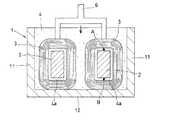
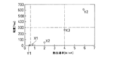
以下、図面を参照して本発明の実施の形態を説明する。図1は本発明のリアクトルの一実施の形態の断面図であり、図2は図1のII−II矢視図であって、製造時に使用する固定治具をともに示した図である。図3は樹脂素材とフィラー素材、フィラーの含有率を変化させて混合材料を生成し、各混合材料から成形される封止樹脂体の粘度と熱伝導率の関係に関する実験結果であり、図4はコイルの押し付け試験の概要を説明した図である。 Embodiments of the present invention will be described below with reference to the drawings. FIG. 1 is a cross-sectional view of an embodiment of the reactor of the present invention, and FIG. 2 is a view taken along the line II-II in FIG. 1 and shows a fixing jig used during manufacturing. FIG. 3 shows the experimental results on the relationship between the viscosity and thermal conductivity of the sealing resin body formed from each mixed material by producing a mixed material by changing the resin material, the filler material, and the filler content. These are the figures explaining the outline | summary of the pressing test of a coil.
図1は、本発明のリアクトルの一実施の形態の断面図であり、図2はそのII−II矢視図である。リアクトル10は、平面視がU型の2つのU型コア21,21の端部同士をギャップ板22,22を介して接着剤にて固着してできる円環状のリアクトルコア2と、このリアクトルコア2のコア外周に隙間を設けた姿勢で形成されたコイル3,3と、このコイル3が形成されたリアクトルコア2を収容するハウジング1と、ハウジング1の内部に樹脂とフィラーの混合材料が充填硬化された封止樹脂体4と、から大略構成されている。なお、ハウジング1の底版12の下方にラジエータ等からのクーリング水を内部で還流させる冷却器などが設けられた構造であってもよい。
FIG. 1 is a cross-sectional view of an embodiment of the reactor of the present invention, and FIG. 2 is a view taken in the direction of arrows II-II. The
封止樹脂体4形成用の混合材料を構成する樹脂とフィラーの組合せとして、樹脂は、ウレタン樹脂、シリコーン樹脂、アクリル樹脂、オレフィン樹脂のいずれか一種から選定でき、フィラーは、シリカ、アルミナ、窒化ホウ素、窒化ケイ素、炭化ケイ素、酸化マグネシウムのいずれか一種またはそれらの組合せのいずれか一種から選定できる。これらの樹脂およびフィラーの組合せでできる混合材料からなる封止樹脂体は高い放熱性能を有し、さらに、その伸び性能も優れていることからコイルやリアクトルコアの熱変形を吸収でき、したがってクラックも生じ難い。
As a combination of resin and filler constituting the mixed material for forming the sealing
たとえばシリコーン樹脂に窒化ホウ素とシリカからなるフィラーを所定の含有率で混ぜ合わせて混合材料を生成し、これをリアクトルコアが配設されたハウジング内に充填硬化させることで図示のリアクトル10が形成される。
For example, a filler made of boron nitride and silica is mixed with silicone resin at a predetermined content to produce a mixed material, which is filled and cured in a housing in which a reactor core is disposed, thereby forming the illustrated
図1,2において、リアクトルコア2とコイル3の間に形成された隙間には高熱伝導性の封止樹脂体4aが充填硬化されており、この封止樹脂体4aによってコイル3やリアクトルコア2で生じる熱を効果的に放熱することができる。
1 and 2, a gap formed between the
リアクトルの製造方法を概説すると、コイル3が形成されたリアクトルコア2をハウジング1内に収容し、ハウジング1の側壁11に取り付けられた板バネ5にてリアクトルコア2の水平方向の位置決めをおこない、この姿勢で図2で示すごとく固定治具6にてコイル3を下方へ押圧することにより(矢印方向)、コイル3とリアクトルコア2双方の間に所定の隙間が形成されながら、双方の水平方向および鉛直方向の位置決めがおこなわれる。
The reactor manufacturing method is outlined. The
この隙間をはじめとするハウジング1の内部に上記する混合材料を充填し、硬化させることで図示するリアクトル10が製造される。
The
[樹脂とフィラー、フィラーの含有率を変化させてできる封止樹脂体を有するリアクトルの実施例および比較例と、絶縁紙を有するリアクトル(比較例)の各熱伝導率に関する実験およびその結果と、粘度に関する実験およびその結果]
本発明者等は、樹脂とフィラー、フィラーの含有率を変化させてできる複数の封止樹脂体をコイルとリアクトルコアの間に形成してなるボビンレス構造のリアクトル(実施例と比較例がある)を試作し、さらに、コイルとリアクトルコアの間に絶縁紙を介装させたリアクトル(比較例)をも試作し、それぞれの所定部位におけるリアクトル駆動時の温度を測定した。なお、この温度測定部位は図1で示すA点とB点でともにコイルとリアクトルコアの間の部位であり(それぞれの温度をT1、T2)、絶縁紙を有する比較例ではこのA点、B点に対応する絶縁紙の部位にて計測した。計測結果を以下の表1に示す。
[Examples and comparative examples of a reactor having a sealing resin body made by changing the resin, filler, filler content, and experiments and results of each thermal conductivity of a reactor having an insulating paper (comparative example) Viscosity experiments and results]
The inventors of the present invention have a bobbin-less reactor in which a plurality of sealing resin bodies formed by changing the resin, filler, and filler content are formed between the coil and the reactor core (there are examples and comparative examples). In addition, a reactor (comparative example) in which insulating paper was interposed between the coil and the reactor core was also prototyped, and the temperature at the time of reactor driving in each predetermined part was measured. Note that this temperature measurement part is a part between the coil and the reactor core at points A and B shown in FIG. 1 (the temperatures are T1 and T2, respectively). In the comparative example having insulating paper, these points A and B The measurement was made at the part of the insulating paper corresponding to the point. The measurement results are shown in Table 1 below.

表1において、実施例1は、ウレタン樹脂と、シリカおよびアルミナからなるフィラーを60重量%程度混合した混合材料からなる封止樹脂体を有したリアクトルである。以下、実施例2は、エポキシ樹脂と、窒化ホウ素およびシリカからなるフィラーを70重量%程度混合した混合材料からなる封止樹脂体を、実施例3は、シリコーン樹脂と、窒化ホウ素およびアルミナからなるフィラーを70重量%程度混合した混合材料からなる封止樹脂体を、それぞれ有している。また、比較例4は、ウレタン樹脂と、シリカを55重量%程度混合した混合材料からなる封止樹脂体を有したリアクトルであり、比較例5は、シリコン樹脂と、窒化ホウ素およびアルミナおよび酸化マグネシウムからなるフィラーを85重量%程度混合した混合材料からなる封止樹脂体を有したものである。 In Table 1, Example 1 is a reactor having a sealing resin body made of a mixed material obtained by mixing about 60% by weight of a urethane resin and a filler made of silica and alumina. Hereinafter, Example 2 is a sealing resin body made of a mixed material obtained by mixing about 70% by weight of an epoxy resin and a filler made of boron nitride and silica, and Example 3 is made of a silicone resin, boron nitride and alumina. Each of the sealing resin bodies is made of a mixed material in which about 70% by weight of filler is mixed. Comparative Example 4 is a reactor having a sealing resin body made of a mixed material in which about 55% by weight of a urethane resin and silica are mixed. Comparative Example 5 is a silicon resin, boron nitride, alumina, and magnesium oxide. It has a sealing resin body made of a mixed material in which about 85% by weight of a filler made of is mixed.
上記各実施例において、実施例1〜3の封止樹脂体は、その熱伝導率が0.7〜4.0(W/mK)と高い熱伝導率を有しており、各実施例のリアクトルでは、発明者等が目標とする基準温度の130℃を下回る結果となっている。 In each of the above examples, the sealing resin bodies of Examples 1 to 3 have a high thermal conductivity of 0.7 to 4.0 (W / mK). In the reactor, the result is below the reference temperature of 130 ° C., which is the target of the inventors.
一方、比較例1〜4では目標基準温度以上の熱ごもりが残ってしまう結果となり、比較例5では、混合材料の粘度が高すぎて注型できないという結果となった。 On the other hand, in Comparative Examples 1 to 4, the result was that a heat stagnation exceeding the target reference temperature remained, and in Comparative Example 5, the viscosity of the mixed material was too high to be cast.
ここで、ボビンレス構造のリアクトルにかかる実施例1〜3と比較例4,5を取り出し、これらの封止樹脂体を形成する混合材料の粘度を計測し、熱伝導率とともにグラフ化した結果を図3に示している。 Here, Examples 1 to 3 and Comparative Examples 4 and 5 relating to the reactor of the bobbin-less structure are taken out, the viscosity of the mixed material forming these sealing resin bodies is measured, and the result of graphing together with the thermal conductivity is shown in FIG. 3 shows.
図3において、実施例1〜3に対応するプロットがそれぞれX1〜X3であり、比較例4,5に対応するプロットがY1,Y2である。この実験結果より、熱伝導率が大きくなることに対応して混合材料の粘度も増加する傾向にあるが、これは、混合材料中のフィラーの含有率が高くなることに起因している。 In FIG. 3, plots corresponding to Examples 1 to 3 are X1 to X3, respectively, and plots corresponding to Comparative Examples 4 and 5 are Y1 and Y2. From this experimental result, the viscosity of the mixed material tends to increase corresponding to the increase in thermal conductivity, which is due to the high filler content in the mixed material.
本発明者等の検証によれば、確実にハウジング内に注型できる粘土の境界としておよそ300Pas(パスカル秒)程度を規定することができ、比較例5(プロットY2)のように600Pasでは全く注型できない。フィラーの素材にもよるが、一般にフィラー含有率が高くなることで混合材料の熱伝導率は高くなるものの、今度はその粘度も増加することで注型できないという事態が生じることから、熱伝導性と注型性の双方を満足するフィラーの含有率は、60〜80重量%程度が好ましいと特定することができる。 According to the verification by the present inventors, about 300 Pas (Pascal second) can be defined as the boundary of the clay that can be reliably cast in the housing, and at 600 Pas as in Comparative Example 5 (plot Y2), I can't type. Although it depends on the material of the filler, the heat conductivity of the mixed material generally increases as the filler content increases. It can be specified that the filler content satisfying both the castability and the castability is preferably about 60 to 80% by weight.
[封止樹脂体の伸び性能に関する実験とその結果]
本発明者等は、混合材料を形成する樹脂を変化させた場合でフィラー素材およびその含有率を一定とした場合の各封止樹脂体を有するリアクトルを試作し、各封止樹脂体の伸び性能を計測した。封止樹脂体の伸び性能は、これが高いほど、リアクトルのヒートサイクルによるコアやコイルの熱変形に対する封止樹脂体の追随性が良好であることを意味している。試験結果を以下の表2に示す。なお、各実施例、比較例ともに、シリカおよびアルミナからなるフィラーを60重量%の含有率で混合している。また、性状がゲル状の樹脂である実施例4,5での針入度に関しては、針が3mm入る状態を30とし、10mm入る状態を100としており、ともにその伸び率は200%よりもはるかに大きな値を呈している。また、クラック発生の有無はX線透過試験によるものである。
[Experiment and result of elongation performance of encapsulating resin]
The inventors made a prototype of a reactor having each sealing resin body when the resin forming the mixed material was changed and the content rate of the filler material was constant, and the elongation performance of each sealing resin body Was measured. The higher the elongation performance of the sealing resin body, the better the followability of the sealing resin body against the thermal deformation of the core and the coil due to the heat cycle of the reactor. The test results are shown in Table 2 below. In each example and comparative example, a filler composed of silica and alumina is mixed at a content of 60% by weight. Moreover, regarding the penetration in Examples 4 and 5 in which the property is a gel-like resin, the state where the needle enters 3 mm is set to 30 and the state where the needle enters 10 mm is set to 100, and the elongation is much higher than 200%. It has a large value. The presence or absence of cracks is determined by the X-ray transmission test.
表2において、実施例1はウレタン樹脂を使用した場合を、実施例2〜5はシリコーン樹脂を使用した場合を、比較例1,2はエポキシ樹脂を使用した場合をそれぞれ示している。さらに、実施例2〜5ではシリコーン樹脂の架橋密度が相違しており、実施例2,3ではゴム状を呈し、実施例4,5ではゲル状を呈している。 In Table 2, Example 1 shows a case where a urethane resin is used, Examples 2 to 5 show a case where a silicone resin is used, and Comparative Examples 1 and 2 show a case where an epoxy resin is used. Furthermore, in Examples 2 to 5, the crosslinking density of the silicone resin is different, Examples 2 and 3 are rubbery, and Examples 4 and 5 are gelated.
表2より、伸び率が30%以上の実施例1〜5ではヒートサイクル試験でクラックの発生は全くないこと、伸び率が30%よりも小さな比較例1,2では所定のサイクル時点でクラックが発生することが特定された。この結果より、封止樹脂体に耐クラック性を要求する場合には、混合材料としてウレタン樹脂、シリコーン樹脂を使用するのが好ましいと結論付けることができる。 From Table 2, in Examples 1 to 5 where the elongation rate is 30% or more, there is no occurrence of cracks in the heat cycle test, and in Comparative Examples 1 and 2 where the elongation rate is less than 30%, cracks occur at a predetermined cycle time. It was identified that it occurred. From this result, when crack resistance is required for the sealing resin body, it can be concluded that it is preferable to use urethane resin or silicone resin as the mixed material.
[コイルとリアクトルコア間に隙間を形成する際の固定治具による押圧荷重に関する実験とその結果]
本発明者等は、図2で示す固定治具にてコイルを押圧する際に、該コイルを変形させない押圧荷重をコイルモデルを使用して実証した。図4はこのコイルモデルM1に治具モデルM2を押圧している状況を説明した図である。なお、図中のa1は50mm、a2は60mm、t1は6mm、t2は10mmのモデル寸法である。実験結果を以下の表3に示す。
[Experiment and results of pressing load by fixture when forming gap between coil and reactor]
The present inventors have demonstrated, using a coil model, a pressing load that does not deform the coil when the coil is pressed by the fixing jig shown in FIG. FIG. 4 is a diagram illustrating a situation where the jig model M2 is pressed against the coil model M1. In the figure, a1 is a model dimension of 50 mm, a2 is 60 mm, t1 is 6 mm, and t2 is 10 mm. The experimental results are shown in Table 3 below.
表3より、コイルを固定治具によって押圧しながら混合材料を充填する際の押圧力は20〜2000N程度の範囲に調整されるのが好ましいことが特定された。 From Table 3, it was specified that the pressing force when filling the mixed material while pressing the coil with a fixing jig is preferably adjusted to a range of about 20 to 2000N.
上記する本発明のリアクトルによれば、コイルとコア間に高熱伝導性の樹脂、フィラーからなる混合材料が充填硬化されてなる封止樹脂体が形成されていることで、放熱性能と耐クラック性能に優れたリアクトルを得ることができる。さらに、フィラー素材やその含有率を調整することにより、ハウジング内に確実に混合材料が充填された高品質なリアクトルを得ることができる。この高品質で高性能なリアクトルは、搭載機器に高性能化が要求される近時のハイブリッド車や電気自動車等への適用に最適である。 According to the reactor of the present invention described above, a sealing resin body formed by filling and curing a mixed material consisting of a highly heat conductive resin and filler between the coil and the core is formed, so that heat dissipation performance and crack resistance performance are achieved. It is possible to obtain an excellent reactor. Furthermore, by adjusting the filler material and the content thereof, a high-quality reactor in which the mixed material is reliably filled in the housing can be obtained. This high-quality, high-performance reactor is optimal for application to recent hybrid vehicles, electric vehicles, and the like that require higher performance in the on-board equipment.
以上、本発明の実施の形態を図面を用いて詳述してきたが、具体的な構成はこの実施形態に限定されるものではなく、本発明の要旨を逸脱しない範囲における設計変更等があっても、それらは本発明に含まれるものである。 The embodiment of the present invention has been described in detail with reference to the drawings. However, the specific configuration is not limited to this embodiment, and there are design changes and the like without departing from the gist of the present invention. They are also included in the present invention.
1…ハウジング、11…側壁、12…底版、2…リアクトルコア、21…U型コア、22…ギャップ板、3…コイル、4…封止樹脂体、4a…コイルとコア間の封止樹脂体、5…板バネ、6…固定治具、10…リアクトル、M1…コイルモデル、M2…治具モデル
DESCRIPTION OF
Claims (3)
少なくとも、2つの平面視がU型のU型コアと、該U型コア間に介装されたギャップ板と、からなり、ハウジング内に収容されたリアクトルコアと、
リアクトルコアの外周において該リアクトルコアの周面と隙間をもって、かつ、ボビンレスの姿勢で形成されるコイルと、
リアクトルコアとコイルの間の前記隙間を含む前記ハウジング内に充填硬化された熱伝導性を有する樹脂とフィラーとからなる封止樹脂体と、からなり、
前記封止樹脂体が0.7〜4.0(W/mK)の範囲の熱伝導率を有していることを特徴とする、リアクトル。 A housing;
A reactor core, which is composed of at least two U-shaped cores in a plan view, and a gap plate interposed between the U-shaped cores and housed in the housing;
A coil formed in a bobbin-less posture with a clearance from the peripheral surface of the reactor core on the outer periphery of the reactor core;
A sealing resin body composed of a resin having a thermal conductivity filled and cured in the housing including the gap between the reactor core and the coil, and a filler,
The reactor, wherein the sealing resin body has a thermal conductivity in a range of 0.7 to 4.0 (W / mK).
Priority Applications (1)
| Application Number | Priority Date | Filing Date | Title |
|---|---|---|---|
| JP2007264194A JP2009094328A (en) | 2007-10-10 | 2007-10-10 | Reactor |
Applications Claiming Priority (1)
| Application Number | Priority Date | Filing Date | Title |
|---|---|---|---|
| JP2007264194A JP2009094328A (en) | 2007-10-10 | 2007-10-10 | Reactor |
Publications (1)
| Publication Number | Publication Date |
|---|---|
| JP2009094328A true JP2009094328A (en) | 2009-04-30 |
Family
ID=40666006
Family Applications (1)
| Application Number | Title | Priority Date | Filing Date |
|---|---|---|---|
| JP2007264194A Withdrawn JP2009094328A (en) | 2007-10-10 | 2007-10-10 | Reactor |
Country Status (1)
| Country | Link |
|---|---|
| JP (1) | JP2009094328A (en) |
Cited By (7)
| Publication number | Priority date | Publication date | Assignee | Title |
|---|---|---|---|---|
| JP2011199227A (en) * | 2010-03-24 | 2011-10-06 | Toyota Motor Corp | Reactor and power converter |
| JP2011211102A (en) * | 2010-03-30 | 2011-10-20 | Toyota Industries Corp | Reactor |
| WO2014185296A1 (en) * | 2013-05-16 | 2014-11-20 | 信越化学工業株式会社 | Thermally conductive silicone adhesive composition for reactor and reactor |
| WO2015068265A1 (en) | 2013-11-08 | 2015-05-14 | 三菱電機株式会社 | Electromagnetic induction apparatus |
| JP2016143827A (en) * | 2015-02-04 | 2016-08-08 | 住友電気工業株式会社 | Composite material, magnetic core for magnetic component and reactor and converter, and electric power conversion system |
| US20180068776A1 (en) * | 2016-09-08 | 2018-03-08 | Fanuc Corporation | Reactor including first end plate and second end plate |
| CN112863815A (en) * | 2019-11-27 | 2021-05-28 | 三菱电机株式会社 | Power conversion device |
-
2007
- 2007-10-10 JP JP2007264194A patent/JP2009094328A/en not_active Withdrawn
Cited By (13)
| Publication number | Priority date | Publication date | Assignee | Title |
|---|---|---|---|---|
| JP2011199227A (en) * | 2010-03-24 | 2011-10-06 | Toyota Motor Corp | Reactor and power converter |
| JP2011211102A (en) * | 2010-03-30 | 2011-10-20 | Toyota Industries Corp | Reactor |
| US9424977B2 (en) | 2013-05-16 | 2016-08-23 | Shin-Etsu Chemical Co., Ltd. | Thermally conductive silicone adhesive composition for reactor and reactor |
| WO2014185296A1 (en) * | 2013-05-16 | 2014-11-20 | 信越化学工業株式会社 | Thermally conductive silicone adhesive composition for reactor and reactor |
| WO2015068265A1 (en) | 2013-11-08 | 2015-05-14 | 三菱電機株式会社 | Electromagnetic induction apparatus |
| WO2016125632A1 (en) * | 2015-02-04 | 2016-08-11 | 株式会社オートネットワーク技術研究所 | Composite material, magnetic core for magnetic part, reactor, converter and power conversion apparatus |
| JP2016143827A (en) * | 2015-02-04 | 2016-08-08 | 住友電気工業株式会社 | Composite material, magnetic core for magnetic component and reactor and converter, and electric power conversion system |
| US10410774B2 (en) | 2015-02-04 | 2019-09-10 | Autonetworks Technologies, Ltd. | Composite material, magnetic core for magnetic component, reactor, converter, and power conversion device |
| US20180068776A1 (en) * | 2016-09-08 | 2018-03-08 | Fanuc Corporation | Reactor including first end plate and second end plate |
| US10580565B2 (en) * | 2016-09-08 | 2020-03-03 | Fanuc Corporation | Reactor including first end plate and second end plate |
| CN112863815A (en) * | 2019-11-27 | 2021-05-28 | 三菱电机株式会社 | Power conversion device |
| JP2021086895A (en) * | 2019-11-27 | 2021-06-03 | 三菱電機株式会社 | Power conversion device |
| CN112863815B (en) * | 2019-11-27 | 2024-04-12 | 三菱电机株式会社 | Power conversion device |
Similar Documents
| Publication | Publication Date | Title |
|---|---|---|
| JP4466684B2 (en) | Reactor | |
| JP4888324B2 (en) | Reactor manufacturing method | |
| JP5429694B2 (en) | Reactor and converter | |
| JP5626466B2 (en) | Reactor and manufacturing method thereof | |
| JP4862751B2 (en) | Reactor and manufacturing method thereof | |
| JP2009094328A (en) | Reactor | |
| JP2009231495A (en) | Reactor | |
| JP5343387B2 (en) | Reactor and converter | |
| JP5083258B2 (en) | Reactor | |
| JP4924949B2 (en) | Reactor | |
| JP2008283730A (en) | Split stator for electric motor, stator for electric motor equipped with this split stator, electric motor equipped with this stator for electric motor, and manufacturing method of split stator for electric motor | |
| JP2007215335A (en) | Stator for motor and motor equipped with this stator | |
| WO2010067414A1 (en) | Reactor and method for manufacturing the same | |
| JP2012124401A (en) | Reactor and manufacturing method of the same | |
| JP2015012272A (en) | Reactor | |
| JP2008199720A (en) | Power supply module | |
| JP2007215334A (en) | Stator for motor, and motor | |
| JP5246601B2 (en) | Reactor | |
| JP5556692B2 (en) | Reactor | |
| JP2008199721A (en) | Power supply module | |
| JP2016025137A (en) | Reactor device | |
| JP2014053521A (en) | Reactor and manufacturing method therefor | |
| JP2015222804A (en) | Reactor | |
| JP7130188B2 (en) | Reactor | |
| JP2017041497A (en) | Reactor |
Legal Events
| Date | Code | Title | Description |
|---|---|---|---|
| A300 | Application deemed to be withdrawn because no request for examination was validly filed |
Free format text: JAPANESE INTERMEDIATE CODE: A300 Effective date: 20110104 |