JP4888324B2 - Reactor manufacturing method - Google Patents
Reactor manufacturing method Download PDFInfo
- Publication number
- JP4888324B2 JP4888324B2 JP2007270262A JP2007270262A JP4888324B2 JP 4888324 B2 JP4888324 B2 JP 4888324B2 JP 2007270262 A JP2007270262 A JP 2007270262A JP 2007270262 A JP2007270262 A JP 2007270262A JP 4888324 B2 JP4888324 B2 JP 4888324B2
- Authority
- JP
- Japan
- Prior art keywords
- reactor
- housing
- reactor core
- core
- manufacturing
- Prior art date
- Legal status (The legal status is an assumption and is not a legal conclusion. Google has not performed a legal analysis and makes no representation as to the accuracy of the status listed.)
- Expired - Fee Related
Links
Images


Description
本発明は、電気自動車やハイブリッド車等に搭載されるリアクトルの製造方法に関するものである。 The present invention relates to a method for manufacturing a reactor mounted on an electric vehicle, a hybrid vehicle, or the like.
電力変換回路のリアクトルは、一般に平面視が略横長環状のリアクトルコアの2つの長手部にコイルが形成された姿勢でハウジング(ケース)内に収容されている。このリアクトルコアは複数の電磁鋼板の積層体もしくは圧粉磁心からなる分割コアから構成されており、各分割コア間には非磁性素材のギャップ板が介装されており、ギャップ板とコアは接着剤にて接着固定されてリアクトルコアが形成されている。 A reactor of a power conversion circuit is generally housed in a housing (case) in a posture in which a coil is formed at two longitudinal portions of a reactor ring that is substantially horizontally long in plan view. This reactor core is composed of multiple cores of magnetic steel sheets or split cores consisting of dust cores. A gap plate made of nonmagnetic material is interposed between each split core, and the gap plate and core are bonded. Reactors are formed by adhesive bonding with an agent.
このハウジングの下面(底面)には放熱板(ヒートシンク)が設けてあり、さらにその下方には冷却水やエアを還流させる冷却器が設けられており、コイルに電流が印加した際の発熱を該コイルまたはリアクトルコアからこの放熱板を介し、冷却器を介してクーリングしながら外部へ逃がす構造が一般的である。ここで、ハウジングと該ハウジング内に収容されたリアクトルコアの間には封止用の樹脂体がモールド成形されており、コイルまたはリアクトルコアからの熱はこの封止樹脂体を介して放熱板に伝熱される。なお、リアクトルコアに設けられたコイルと放熱板との間に隙間が形成され、この隙間に上記封止樹脂体が介在してなる、いわゆるフロート構造のリアクトルも存在し、たとえば特許文献1にその一例が開示されている。 A heat radiating plate (heat sink) is provided on the lower surface (bottom surface) of the housing, and a cooler that circulates cooling water and air is provided below the heat sink, and generates heat when current is applied to the coil. In general, a structure is used in which a coil or a reactor core is allowed to escape to the outside through the heat sink and cooling via a cooler. Here, a sealing resin body is molded between the housing and the reactor core accommodated in the housing, and the heat from the coil or the reactor core is transferred to the heat sink via the sealing resin body. Heat is transferred. There is also a so-called float reactor in which a gap is formed between the coil provided in the reactor and the heat dissipation plate, and the sealing resin body is interposed in the gap. An example is disclosed.
上記するフロート構造のリアクトルは勿論のこと、リアクトルコアに設けられたコイルがハウジング底面に当接されたリアクトルにおいては、コイルまたはリアクトルコアとハウジングとの間に放熱性能を有する封止樹脂体が介在していることがリアクトルの放熱性能を確保する上で不可避である。特に、ハウジングはアルミニウムもしくはアルミ合金から成形されるのが一般的であるが、このアルミニウム製のハウジングと封止樹脂体との接着強度は十分にあり、一般にリアクトルの駆動によるヒートサイクルや繰返し振動によって双方の間に剥離が生じる可能性は少ない。 In addition to the float structure reactor described above, in the reactor in which the coil provided in the reactor is in contact with the bottom surface of the housing, a sealing resin body having heat radiation performance is interposed between the coil or the reactor and the housing. This is inevitable in securing the heat dissipation performance of the reactor. In particular, the housing is generally molded from aluminum or an aluminum alloy, but the adhesive strength between the aluminum housing and the sealing resin body is sufficient, and generally due to heat cycles and repeated vibrations driven by the reactor. There is little possibility of delamination between the two.
しかし、リアクトルコアと封止樹脂体の接着強度は相対的に小さく、従来のリアクトルでは、ヒートサイクル等の過程で、このリアクトルコアと封止樹脂体との間で剥離が生じ易いという課題があった。リアクトルコアと封止樹脂体との間で剥離が生じると、剥離箇所にエアギャップが介在することとなり、リアクトルコアからハウジングへの放熱性能が格段に低下してしまう。したがって、リアクトルコアとハウジングの間の接着強度を如何に高めることができるかが当該分野での重要な課題の一つであった。 However, the adhesive strength between the reactor core and the sealing resin body is relatively small, and the conventional reactor has a problem that peeling between the reactor core and the sealing resin body is likely to occur during a process such as a heat cycle. It was. When separation occurs between the reactor core and the sealing resin body, an air gap is interposed at the separation portion, and the heat dissipation performance from the reactor core to the housing is significantly reduced. Therefore, how to increase the adhesive strength between the reactor core and the housing was one of the important issues in the field.
特に電気自動車やハイブリッド車等に車載されるリアクトルは、一般に大電流、大電圧が印加されることから振動も大きく、発熱量も大きいことから、上記するリアクトル構成部材相互の接着姿勢の確保の重要性はより一層高いものである。 In particular, reactors mounted on electric vehicles, hybrid vehicles, etc. generally have large vibrations and large amounts of heat because large currents and voltages are applied, so it is important to ensure the bonding posture between the reactor components described above. The nature is even higher.
しかし、特許文献1に開示のリアクトルをはじめとする従来のリアクトルにおいては、リアクトルコアと封止樹脂体との接着強度が必ずしも高いものではなく、依然として、上記する剥離を抑止するといった課題を解決するに至らない。
However, in the conventional reactor including the reactor disclosed in
本発明は、上記する問題に鑑みてなされたものであり、リアクトルの駆動にともなう繰返し振動やヒートサイクルに対して、リアクトルコアとハウジングとの間に剥離が生じ難いリアクトルを製造する方法を提供することを目的とする。 The present invention has been made in view of the above-described problems, and provides a method for manufacturing a reactor in which separation between a reactor core and a housing is less likely to occur with respect to repetitive vibrations and heat cycles accompanying the driving of the reactor. For the purpose.
前記目的を達成すべく、本発明によるリアクトルの製造方法は、ハウジングと、コイルを具備した姿勢でハウジング内に収容固定されるリアクトルコアと、ハウジング内にシリコーン樹脂が充填硬化されてできる封止樹脂体と、を少なくとも具備するリアクトルの製造方法であって、ハウジング内にコイルを具備するリアクトルコアを収容固定する第1の工程と、次いで、ハウジング内にシリコーン樹脂を含浸硬化させる第2の工程と、を少なくとも具備するリアクトルの製造方法において、前記第1の工程に先行して、少なくともリアクトルコアを予熱しておくことを特徴とするものである。 In order to achieve the above object, a method of manufacturing a reactor according to the present invention includes a housing, a reactor core that is accommodated and fixed in the housing in a posture equipped with a coil, and a sealing resin that is formed by filling and curing a silicone resin in the housing. A first step of housing and fixing a reactor core having a coil in the housing, and then a second step of impregnating and hardening a silicone resin in the housing. In the method for manufacturing a reactor including at least, the reactor is preheated at least in advance of the first step.
ここで、リアクトルコアは、磁性を有する2つのU型コア、またはこれに加えてさらにI型コアがギャップ板を介して接着剤にて接合されて形成されるものである。このU型コアやI型コアは、珪素鋼板を積層してなる積層体から形成してもよく、軟磁性金属粉末または軟磁性金属酸化物粉末が樹脂バインダーで被覆された磁性粉末を加圧成形してなる圧粉磁心から形成してもよい。なお、この軟磁性金属粉末としては、鉄、鉄−シリコン系合金、鉄−窒素系合金、鉄−ニッケル系合金、鉄−炭素系合金、鉄−ホウ素系合金、鉄−コバルト系合金、鉄−リン系合金、鉄−ニッケル−コバルト系合金および鉄−アルミニウム−シリコン系合金などを用いることができる。また、ギャップ板は、例えばアルミナ(Al2O3)やジルコニア(ZrO2)などのセラミックスで成形することができる。 Here, the reactor core is formed by joining two U-shaped cores having magnetism, or in addition to this, an I-type core with an adhesive via a gap plate. The U-type core and I-type core may be formed from a laminate formed by laminating silicon steel plates, and a magnetic powder in which a soft magnetic metal powder or a soft magnetic metal oxide powder is coated with a resin binder is press-formed. You may form from the powder magnetic core formed. As the soft magnetic metal powder, iron, iron-silicon alloy, iron-nitrogen alloy, iron-nickel alloy, iron-carbon alloy, iron-boron alloy, iron-cobalt alloy, iron- Phosphorus alloys, iron-nickel-cobalt alloys, iron-aluminum-silicon alloys, and the like can be used. The gap plate can be formed of ceramics such as alumina (Al 2 O 3 ) or zirconia (ZrO 2 ).
また、ハウジングはアルミニウムやその合金などから成形することができ、その下方(下面)には、このハウジングと別体に成形された、または一体に成形された放熱性台座が設けられていてもよい。なお、この放熱性台座のさらに下方に、ラジエータ等からのクーリング水やクーリングエアが循環する冷却器が設けられている形態もある。 Further, the housing can be formed from aluminum or an alloy thereof, and a heat dissipating base formed separately or integrally with the housing may be provided below (lower surface). . There is also a form in which a cooler in which cooling water or cooling air from a radiator or the like is circulated further below the heat radiating base.
本発明の製造方法で製造されるリアクトルは、既述するフロート構造のリアクトルであってもよいし、コイルとハウジングの底版が当接した形態のリアクトルであってもよい。この製造方法は、たとえば2つのU型コアとギャップ板をそれぞれ成形し、該コアの外周にコイルを形成しながらリアクトルコアを製造し、これを、ハウジング内に収容固定する(第1の工程)。ここで、フロート構造のリアクトルの場合には、ハウジングの底版からリアクトルコアが若干浮いた姿勢でハウジング内に収容固定される。たとえば、ハウジングの底版に段差部を設けておき、コイルが設置される底版箇所に溝を設けておいたり、ハウジング内に板バネ等の固定手段を設けておき、これでリアクトルコアの位置決めをおこなう等の保持方法がある。 The reactor manufactured by the manufacturing method of the present invention may be a reactor having the float structure described above, or may be a reactor in which the coil and the bottom plate of the housing are in contact with each other. In this manufacturing method, for example, two U-shaped cores and a gap plate are formed, a reactor core is manufactured while forming a coil on the outer periphery of the core, and this is accommodated and fixed in the housing (first step). . Here, in the case of a reactor having a float structure, the reactor core is accommodated and fixed in the housing in a posture in which the reactor core slightly floats from the bottom plate of the housing. For example, a step portion is provided in the bottom plate of the housing, a groove is provided in the bottom plate portion where the coil is installed, or a fixing means such as a leaf spring is provided in the housing, thereby positioning the reactor core. There is a holding method.
次いで、第2の工程として、シリコーン樹脂をハウジング内に充填し、これを硬化させることによってリアクトルが製造される。なお、シリコーン樹脂には、シリカやアルミナ、窒化ホウ素などからなるフィラーが適量混合されていてもよい。 Next, as a second step, the reactor is manufactured by filling the housing with a silicone resin and curing it. The silicone resin may be mixed with an appropriate amount of filler made of silica, alumina, boron nitride, or the like.
本発明の製造方法では、この第1の工程に先んじて、たとえばリアクトルコアとハウジングを所定温度まで予熱しておくことにより、リアクトルコアと封止樹脂体の間の接着強度を高めるものである。 In the manufacturing method of the present invention, prior to the first step, for example, the reactor core and the housing are preheated to a predetermined temperature, thereby increasing the adhesive strength between the reactor core and the sealing resin body.
本発明者等の実験によれば、リアクトルコアとハウジングを予熱しておくことにより、予熱なしの従来の製造方法に比して接着強度が増加することが分かっている。 According to experiments by the present inventors, it has been found that preheating the reactor core and the housing increases the adhesive strength as compared with the conventional manufacturing method without preheating.
さらに、本発明者等の実験によれば、予めリアクトルコアのみを予熱しておくことで、リアクトルコアと封止樹脂体の間の接着強度をより一層高めることができることが実証されている。 Furthermore, according to experiments by the present inventors, it has been demonstrated that the adhesive strength between the reactor core and the sealing resin body can be further increased by preheating only the reactor core in advance.
シリコーン樹脂からなる封止樹脂体と、たとえば圧粉磁心からなるリアクトルコアとの接着強度の増加に関し、少なくともリアクトルコアを予熱した後にハウジング内に収容し、封止樹脂をハウジング内に充填することでリアクトルコアと封止樹脂体の間の接着強度が増加する理由の一つとして、予熱によってリアクトルコア表面の濡れ性が良好になり、特にシリコーン樹脂の場合にはそのアンカー効果が発揮される結果、双方の間の接着強度が増加すると考えられる。 With regard to an increase in adhesive strength between a sealing resin body made of silicone resin and a reactor core made of, for example, a dust core, at least the reactor core is preheated and then housed in the housing, and the sealing resin is filled in the housing As one of the reasons why the adhesive strength between the reactor core and the sealing resin body increases, the wettability of the reactor core surface is improved by preheating, especially in the case of silicone resin, the anchor effect is exhibited, It is thought that the adhesive strength between the two increases.
また、上記する予熱の温度条件に関しては、少なくともリアクトルコアが70〜120℃の範囲に予熱された場合に、高い接着強度の増加が得られることが実証されている。 In addition, regarding the preheating temperature condition described above, it has been demonstrated that a high increase in adhesive strength can be obtained at least when the reactor core is preheated in the range of 70 to 120 ° C.
ここで、リアクトルコアを120℃よりも高く予熱してしまうと、シリコーン樹脂の硬化温度が120℃程度であることから、双方の接着部のみが急激に硬化してしまうことから好ましくない。 Here, if the reactor core is preheated to a temperature higher than 120 ° C., the curing temperature of the silicone resin is about 120 ° C., which is not preferable because only the bonded portions of both are rapidly cured.
本発明のリアクトルの製造方法によれば、少なくともリアクトルコアを予め所定温度範囲に予熱しておくだけの簡易な方法により、封止樹脂体とリアクトルコアの間の接着強度(または剥離強度)を従来リアクトルに比して大幅に増加させることができ、製造コストを高騰させることなく耐久性および放熱性に優れた高品質なリアクトルを得ることが可能となる。 According to the method for manufacturing a reactor of the present invention, the adhesive strength (or peel strength) between the sealing resin body and the reactor core is conventionally increased by a simple method in which at least the reactor core is preheated to a predetermined temperature range in advance. As compared with the reactor, it is possible to greatly increase, and it is possible to obtain a high-quality reactor excellent in durability and heat dissipation without increasing the manufacturing cost.
本発明の製造方法で製造されたリアクトルは、上記のごとく放熱性能に優れ、耐久性の高いリアクトルであることから、高性能で耐久性のある搭載機器を有することを課題とする近時のハイブリッド車や電気自動車への適用に最適である。 Since the reactor manufactured by the manufacturing method of the present invention is a reactor having excellent heat dissipation performance and high durability as described above, it is a recent hybrid that has a problem of having a high-performance and durable mounting device. Ideal for applications in cars and electric vehicles.
以上の説明から理解できるように、本発明のリアクトルの製造方法によれば、リアクトルコアとハウジングの間の接着強度を格段に高めることができ、よって長期に亘って優れた放熱性能を有するリアクトルを得ることができる。また、この製造方法は、組付け等に先行して少なくともリアクトルコアを予熱しておくだけの簡易なものであり、製造コストを何ら高騰させるものではない。 As can be understood from the above description, according to the reactor manufacturing method of the present invention, the adhesive strength between the reactor core and the housing can be remarkably increased, and thus a reactor having excellent heat dissipation performance over a long period of time can be obtained. Obtainable. In addition, this manufacturing method is simple enough to preheat at least the reactor core prior to assembly or the like, and does not raise the manufacturing cost at all.
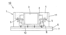
以下、図面を参照して本発明の実施の形態を説明する。図1は本発明の製造方法によって製造されるリアクトルの一実施の形態の縦断図であり、図2は図1のII部の拡大図である。図3はリアクトルコアと封止樹脂体とハウジング底版とからなるテストピースに関し、予熱部位と予熱温度を変化させてできるテストピースを示したものであって、図3aはリアクトルコアのみを70〜120℃の範囲で予熱した実施例を示しており、図3bは予熱なしの比較例を示しており、図3cはリアクトルコアを40〜65℃の範囲で予熱した比較例を示しており、図3dはリアクトルコアとハウジングを80〜120℃の範囲で予熱した比較例を示している。図4は図3で示すテストピースに引張試験を実施している状況を説明した図であり、図5は図3の実施例および比較例ごとの接着強度に関する実験結果を示した図である。なお、図示するリアクトルの実施の形態はフロート構造のリアクトルであるが、本発明の製造方法によってできるリアクトルはコイルとハウジング底版とが当接した形態のリアクトルも包含することは勿論のことである。さらに、リアクトルコアは図示例の圧粉磁心からなるもの以外にも電磁鋼板を積層させた鋼板積層体からなるものも包含されるものである。 Embodiments of the present invention will be described below with reference to the drawings. FIG. 1 is a longitudinal sectional view of an embodiment of a reactor manufactured by the manufacturing method of the present invention, and FIG. 2 is an enlarged view of a portion II in FIG. FIG. 3 shows a test piece formed by changing a preheating portion and a preheating temperature with respect to a test piece made up of a reactor core, a sealing resin body, and a housing bottom plate. FIG. Fig. 3b shows a comparative example without preheating, Fig. 3c shows a comparative example in which the reactor core is preheated in the range of 40 to 65 ° C, and Fig. 3d Shows a comparative example in which the reactor core and the housing are preheated in the range of 80 to 120 ° C. FIG. 4 is a diagram illustrating a situation in which a tensile test is performed on the test piece illustrated in FIG. 3, and FIG. 5 is a diagram illustrating an experimental result regarding the adhesive strength for each of the example and the comparative example of FIG. Although the illustrated embodiment of the reactor is a reactor having a float structure, it goes without saying that the reactor formed by the manufacturing method of the present invention includes a reactor in which the coil and the housing bottom plate are in contact with each other. Further, the reactor core includes a steel plate laminate in which electromagnetic steel plates are laminated in addition to the dust core shown in the drawing.
図1は、本発明の製造方法によって製造されたリアクトルの一実施の形態の縦断図であり、図2はそのII部の拡大図である。リアクトル10は、内部にラジエータ等からのクーリング水を還流させる冷却器7と、この冷却器7に固定された放熱性台座6、この放熱性台座6の上面で接着固定されたアルミニウム製のハウジング1と、該ハウジング1内に固定部材5を介して収容固定され、コイル3が形成されたリアクトルコア2と、ハウジング1内にシリコーン樹脂が充填硬化されてできる封止樹脂体4と、から大略構成されている。なお、図示例では、ハウジング1の側壁11に段差部を設け、この段差部に固定部材5を設けた構造を示しているが、この段差部にリアクトルコア2の端部を直接載置した構造であってもよい。
FIG. 1 is a longitudinal sectional view of an embodiment of a reactor manufactured by the manufacturing method of the present invention, and FIG. 2 is an enlarged view of a portion II thereof. The
リアクトルコアは、平面視がU型の2つのU型コアの端部同士をギャップ板を介して接着剤にて固着して全体が円環状に形成されている。このU型コアは、磁性粉末を加圧成形してなる圧粉磁心から形成されており、ギャップ板はセラミックスから成形されている。 The reactor core is formed in an annular shape as a whole by adhering the ends of two U-shaped cores having a U-shape in plan view with an adhesive via a gap plate. This U-shaped core is formed from a powder magnetic core formed by pressure-molding magnetic powder, and the gap plate is formed from ceramics.
封止樹脂体4は、シリコーン樹脂にシリカやアルミナ等のフィラーが適量混合されてできる混合材料がハウジング1内に充填され、硬化することで形成される。
The sealing
リアクトル駆動時には、コイル3やリアクトルコア2に発熱が生じるが、この熱は、たとえば図中の矢印のごとく、リアクトルコア2やコイル3の下方の封止樹脂体4を介し、さらにその下方のハウジング1の底版12、放熱性台座6を介して冷却器7に放熱される。
When the reactor is driven, heat is generated in the
次に、図1で示すリアクトル10の製造方法を概説する。
Next, the manufacturing method of the
まず、U型コアやギャップ板を個別に製造し、コイルボビンまわりにコイル3を形成したものをリアクトルコアの外周に設置しながら全体が円環状を呈するリアクトルコア2を製造する。このリアクトルコア2を所定温度に予熱し、予熱されたリアクトルコア2の端部をハウジング1内の固定部材5を介して該ハウジング1内に収容固定する。この段階で、コイル3とハウジング1の底版12の間には隙間が形成されたフロート構造が形成される。なお、リアクトルコア2のみならず、ハウジング1も同程度の温度条件で予熱しておいてもよい。
First, a U-shaped core and a gap plate are individually manufactured, and a
次いで、ハウジング1内にシリコーン樹脂にフィラーが適量混合された混合材料を充填し、その硬化を待ってリアクトル10が製造される。
Next, the
上記する余熱に関しては、リアクトルコア2のみを70〜120℃の範囲の温度で予熱するのが最も好ましいが、リアクトルコア2とハウジング1の双方を同範囲の温度で予熱する方法であってもよい。
Regarding the above-mentioned residual heat, it is most preferable to preheat only the
この予熱工程をリアクトルコア2とハウジング1の組付け工程前に実施することにより、図2の拡大図で示すリアクトルコア2と封止樹脂体4の間の界面の接着強度(または剥離強度)を高めることができ、リアクトルコア2のみを予熱した場合にはその効果は一層高くなる。
By performing this preheating process before the assembly process of the
[予熱部位と予熱温度を変化させた場合の接着強度に与える影響を検証した実験とその結果]
本発明者等は、図2の拡大図で示すリアクトルコアと封止樹脂体とハウジング底版の各一部からなるテストピースを試作し、その試作過程でその一部を予熱するとともに予熱温度を変化させてテストピースを作り、各テストピースにおけるリアクトルコアと封止樹脂体の間の接着強度を引張試験に基づいて計測した。
[Experiment to verify the effect on adhesive strength when changing preheating part and preheating temperature and results]
The inventors have made a test piece consisting of a part of each of the reactor core, the sealing resin body, and the housing bottom plate shown in the enlarged view of FIG. 2, and preheating a part of the test piece and changing the preheating temperature. Test pieces were prepared, and the adhesive strength between the reactor core and the sealing resin body in each test piece was measured based on a tensile test.
図3は試作された各テストピースを示しており、各ケースともに、T1はテストピースTのリアクトルコア部分を、T2はシリコーン樹脂からなるテストピースTの封止樹脂体部分を、T3はテストピースTのアルミニウム製のハウジング底版部分をそれぞれ示している。ここで、図3aは、リアクトルコア部分T1のみを70〜120℃の所定温度で予熱してできるテストピースであり、実施例1〜4の4ケースのテストピースのそれぞれのリアクトルコアを70℃、80℃、100℃、120℃で予熱したものである。 FIG. 3 shows the prototyped test pieces. In each case, T1 represents the reactor part of the test piece T, T2 represents the sealing resin body portion of the test piece T made of silicone resin, and T3 represents the test piece. Each of the aluminum housing bottom plates of T is shown. Here, FIG. 3a is a test piece that is obtained by preheating only the reactor core portion T1 at a predetermined temperature of 70 to 120 ° C., and each reactor core of the four case test pieces of Examples 1 to 4 is 70 ° C. Preheated at 80 ° C, 100 ° C and 120 ° C.
図3bは、従来の製造方法によるテストピースを示しており、どの部位も予熱することなく製作したものであり、これを比較例1とする。なお、予熱なしの場合は、各部材は製作時点の常温である23℃を示している。 FIG. 3 b shows a test piece according to the conventional manufacturing method, which is manufactured without preheating, and this is referred to as Comparative Example 1. In the case of no preheating, each member shows a normal temperature of 23 ° C. at the time of manufacture.
図3cは、リアクトルコアのみを予熱したテストピースであるが、この予熱温度を70℃未満の温度で予熱したものであり、40℃、50℃、65℃の各予熱温度のテストピースをそれぞれ比較例2,3,4とする。なお、ここでは、これらのテストピースを比較例と位置づけているが、これらも部材を予熱するという本発明の製造方法の範囲に含まれるものであり、予熱なしの従来方法による比較例1との比較においては実施例と位置づけることができる。最適な予熱範囲を確定する上で、実施例1〜4との比較において、ここでは比較例としているに過ぎない。 Fig. 3c shows the test piece preheated only for the reactor core. This preheated temperature is preheated at a temperature lower than 70 ° C, and the test pieces at preheating temperatures of 40 ° C, 50 ° C and 65 ° C are compared. Example 2, 3 and 4. In addition, although these test pieces are positioned as comparative examples here, they are also included in the scope of the manufacturing method of the present invention in which the members are preheated, and compared with Comparative Example 1 by the conventional method without preheating. In comparison, it can be positioned as an example. In determining the optimum preheating range, the comparison with Examples 1 to 4 is only a comparative example.
図3dは、リアクトルコアとハウジング底版を予熱したテストピースであり、これらの予熱温度を80〜120℃の範囲の所定の温度で予熱したものであり、80℃、100℃、120℃の各余熱温度のテストピースをそれぞれ比較例5,6,7とする。なお、この比較例5〜7も部材を予熱するという本発明の製造方法の範囲に含まれるものであり、リアクトルコアのみを最適な温度範囲で予熱するという実施例1〜4と比較する上でここでは比較例としているに過ぎず、比較例1との比較においては実施例と位置づけることができるものである。 FIG. 3d is a test piece in which the reactor core and the bottom plate of the housing are preheated. These preheat temperatures are preheated at a predetermined temperature in the range of 80 to 120 ° C., and each residual heat at 80 ° C., 100 ° C., and 120 ° C. The temperature test pieces are referred to as Comparative Examples 5, 6, and 7, respectively. The comparative examples 5 to 7 are also included in the scope of the manufacturing method of the present invention in which the members are preheated. In comparison with the examples 1 to 4 in which only the reactor core is preheated in the optimum temperature range. Here, it is only a comparative example, and in comparison with comparative example 1, it can be positioned as an example.
上記する各ケースごとにテストピースを3つ用意し、図4で示すごとく上下から引張力を付与する引張試験にかけ、この引張試験での試験結果から、リアクトルコアと封止樹脂体の間の接着強度を求めた。なお、封止樹脂体とハウジング底版の間の引張強度はリアクトルコアと封止樹脂体のそれと比較して十分に大きく、したがって、いずれの試験においてもリアクトルコアと封止樹脂体の間でまず剥離が生じている。試験の結果を以下の表1および図5に示す。 Three test pieces are prepared for each case described above, and subjected to a tensile test to apply a tensile force from above and below as shown in FIG. 4, and from the test result in this tensile test, adhesion between the reactor core and the sealing resin body is performed. The strength was determined. Note that the tensile strength between the sealing resin body and the bottom plate of the housing is sufficiently larger than that of the reactor core and the sealing resin body. Has occurred. The results of the test are shown in Table 1 below and FIG.
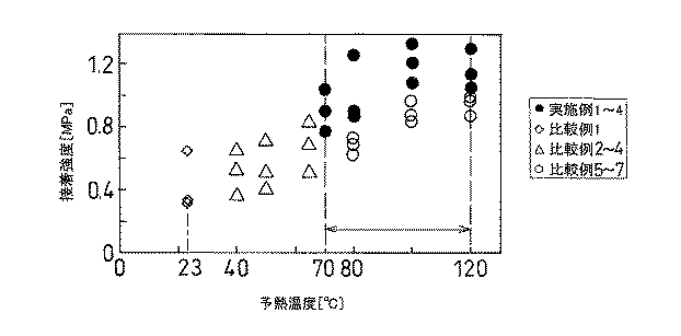
上表1および図5の結果より、各ケースともに試験片ごとにハウジング底版表面の平坦性等に起因する誤差があるものの、実施例1〜4のリアクトルコアのみを70〜120℃の範囲で予熱した場合は、0.8MPa以上の高い接着強度が得られることが実証された。 From the results shown in Table 1 and FIG. 5, only the reactor cores of Examples 1 to 4 were preheated in the range of 70 to 120 ° C., although there were errors due to the flatness of the housing bottom plate surface for each test piece in each case. In this case, it was proved that a high adhesive strength of 0.8 MPa or more can be obtained.
従来の製造方法で作られた比較例1と本発明の製造方法で作られた比較例2〜7を比較すると、いずれも比較例1に比して接着強度は増加しており、比較例2〜7も十分な効果が得られていることが分かる。 When the comparative example 1 made by the conventional manufacturing method and the comparative examples 2 to 7 made by the manufacturing method of the present invention are compared, the adhesive strength is increased as compared with the comparative example 1, and the comparative example 2 It can be seen that a sufficient effect is obtained for ˜7.
さらに、比較例2〜7内で比較すると、最適な温度範囲である80〜120℃でリアクトルコアおよびハウジングを予熱する方が、最適範囲を下回る温度範囲でリアクトルコアのみを予熱する場合に比して接着強度が高くなることが実証されている。 Furthermore, when compared in Comparative Examples 2 to 7, preheating the reactor core and the housing at an optimum temperature range of 80 to 120 ° C. is more than when preheating only the reactor core at a temperature range lower than the optimum range. It has been demonstrated that the adhesive strength is high.
また、実施例2〜4と比較例5〜7を比較することにより、リアクトルコアのみを予熱する方が接着強度が高くなることが実証されている。 Moreover, it is demonstrated by comparing Examples 2-4 and Comparative Examples 5-7 that the adhesive strength is higher when only the reactor core is preheated.
本実験の結果より、リアクトルコアのみを70〜120℃の範囲で予熱した場合にリアクトルコアと封止樹脂体の接着強度が最も高くなることが実証された。 From the results of this experiment, it was demonstrated that the adhesive strength between the reactor core and the sealing resin body becomes the highest when only the reactor core is preheated in the range of 70 to 120 ° C.
以上、本発明の実施の形態を図面を用いて詳述してきたが、具体的な構成はこの実施形態に限定されるものではなく、本発明の要旨を逸脱しない範囲における設計変更等があっても、それらは本発明に含まれるものである。 The embodiment of the present invention has been described in detail with reference to the drawings. However, the specific configuration is not limited to this embodiment, and there are design changes and the like without departing from the gist of the present invention. They are also included in the present invention.
1…ハウジング、11…側壁、12…底版、2…リアクトルコア、3…コイル、4…封止樹脂体、5…固定部材、6…放熱性台座、7…冷却器、10…リアクトル、T…テストピース、T1…テストピースのリアクトルコア部分、T2…テストピースの封止樹脂体部分、T3…テストピースのハウジング底版部分
DESCRIPTION OF
Claims (2)
前記第1の工程に先行して、前記リアクトルコアのみを70〜120℃の範囲に予熱しておき、このことによってリアクトルコアと封止樹脂体の間の接着強度の増加が図られていることを特徴とする、リアクトルの製造方法。 A reactor manufacturing method comprising at least a housing, a reactor core accommodated and fixed in the housing in a posture including a coil, and a sealing resin body formed by filling and curing a silicone resin in the housing. In a method of manufacturing a reactor, comprising at least a first step of accommodating and fixing a reactor core having a coil therein, and then a second step of impregnating and curing a silicone resin in the housing,
Prior to the first step, aft preheated only in the range of 70 to 120 ° C. The reactor core, the increase in the adhesion strength between the reactor core and the resin portion is achieved by the fact A method for manufacturing a reactor.
The method of manufacturing a reactor according to claim 1 , wherein the reactor is a vehicle-mounted reactor mounted on a hybrid vehicle or an electric vehicle.
Priority Applications (1)
| Application Number | Priority Date | Filing Date | Title |
|---|---|---|---|
| JP2007270262A JP4888324B2 (en) | 2007-10-17 | 2007-10-17 | Reactor manufacturing method |
Applications Claiming Priority (1)
| Application Number | Priority Date | Filing Date | Title |
|---|---|---|---|
| JP2007270262A JP4888324B2 (en) | 2007-10-17 | 2007-10-17 | Reactor manufacturing method |
Publications (2)
| Publication Number | Publication Date |
|---|---|
| JP2009099793A JP2009099793A (en) | 2009-05-07 |
| JP4888324B2 true JP4888324B2 (en) | 2012-02-29 |
Family
ID=40702508
Family Applications (1)
| Application Number | Title | Priority Date | Filing Date |
|---|---|---|---|
| JP2007270262A Expired - Fee Related JP4888324B2 (en) | 2007-10-17 | 2007-10-17 | Reactor manufacturing method |
Country Status (1)
| Country | Link |
|---|---|
| JP (1) | JP4888324B2 (en) |
Cited By (1)
| Publication number | Priority date | Publication date | Assignee | Title |
|---|---|---|---|---|
| CN110504089A (en) * | 2018-05-18 | 2019-11-26 | 欧姆龙株式会社 | Magnetic part and electronic equipment |
Families Citing this family (13)
| Publication number | Priority date | Publication date | Assignee | Title |
|---|---|---|---|---|
| JP5395564B2 (en) * | 2009-08-11 | 2014-01-22 | 株式会社タムラ製作所 | Inductor |
| DE112009005402B4 (en) | 2009-11-26 | 2014-07-31 | Toyota Jidosha Kabushiki Kaisha | Reactor safety structure |
| JPWO2011089941A1 (en) * | 2010-01-20 | 2013-05-23 | 住友電気工業株式会社 | Reactor |
| JP4947503B1 (en) * | 2010-09-22 | 2012-06-06 | 住友電気工業株式会社 | Reactor, converter, and power converter |
| WO2012090258A1 (en) | 2010-12-27 | 2012-07-05 | トヨタ自動車株式会社 | Reactor device |
| WO2012101764A1 (en) | 2011-01-26 | 2012-08-02 | トヨタ自動車株式会社 | Reactor and reactor apparatus |
| EP2725591B9 (en) | 2011-06-27 | 2016-05-18 | Toyota Jidosha Kabushiki Kaisha | Inductor and manufacturing method therefor |
| DE112011105382B4 (en) | 2011-06-27 | 2016-06-30 | Toyota Jidosha Kabushiki Kaisha | Throttle and manufacturing process for it |
| WO2013001592A1 (en) | 2011-06-27 | 2013-01-03 | トヨタ自動車株式会社 | Inductor and manufacturing method therefor |
| JP6268509B2 (en) * | 2012-08-10 | 2018-01-31 | パナソニックIpマネジメント株式会社 | Reactor device |
| WO2014080462A1 (en) * | 2012-11-21 | 2014-05-30 | 三洋電機株式会社 | Power conversion apparatus |
| JP6611081B2 (en) | 2017-02-28 | 2019-11-27 | 株式会社オートネットワーク技術研究所 | Reactor |
| JP2022045275A (en) * | 2020-09-08 | 2022-03-18 | 株式会社オートネットワーク技術研究所 | Reactor, converter, and power conversion device |
-
2007
- 2007-10-17 JP JP2007270262A patent/JP4888324B2/en not_active Expired - Fee Related
Cited By (2)
| Publication number | Priority date | Publication date | Assignee | Title |
|---|---|---|---|---|
| CN110504089A (en) * | 2018-05-18 | 2019-11-26 | 欧姆龙株式会社 | Magnetic part and electronic equipment |
| US11581122B2 (en) | 2018-05-18 | 2023-02-14 | Omron Corporation | Magnetic part and electronic apparatus |
Also Published As
| Publication number | Publication date |
|---|---|
| JP2009099793A (en) | 2009-05-07 |
Similar Documents
| Publication | Publication Date | Title |
|---|---|---|
| JP4888324B2 (en) | Reactor manufacturing method | |
| JP4466684B2 (en) | Reactor | |
| JP4862751B2 (en) | Reactor and manufacturing method thereof | |
| US10170235B2 (en) | Reactor | |
| JP5429694B2 (en) | Reactor and converter | |
| JP5626466B2 (en) | Reactor and manufacturing method thereof | |
| US8749335B2 (en) | Reactor | |
| JP2009231495A (en) | Reactor | |
| JP6361884B2 (en) | Reactor and reactor manufacturing method | |
| WO2015190215A1 (en) | Reactor | |
| EP2525475A1 (en) | Stator structure and stator manufacturing method | |
| JP2008028290A (en) | Reactor device and assembly method thereof | |
| JP2012209333A (en) | Reactor and manufacturing method of the same | |
| JP2012124401A (en) | Reactor and manufacturing method of the same | |
| WO2010067414A1 (en) | Reactor and method for manufacturing the same | |
| JP2008042051A (en) | Reactor | |
| JP2015012272A (en) | Reactor | |
| JP2013118208A (en) | Reactor | |
| JP2009094328A (en) | Reactor | |
| JP2010103307A (en) | Reactor | |
| JP2011086801A (en) | Reactor, and method of manufacturing the same | |
| JP7133685B2 (en) | Reactor and its manufacturing method | |
| WO2013118524A1 (en) | Reactor, converter, and power conversion device, and core material for reactor | |
| JP6070928B2 (en) | Reactor, converter, and power converter | |
| JP2011159854A (en) | Reactor |
Legal Events
| Date | Code | Title | Description |
|---|---|---|---|
| A621 | Written request for application examination |
Free format text: JAPANESE INTERMEDIATE CODE: A621 Effective date: 20100205 |
|
| A977 | Report on retrieval |
Free format text: JAPANESE INTERMEDIATE CODE: A971007 Effective date: 20110613 |
|
| A131 | Notification of reasons for refusal |
Free format text: JAPANESE INTERMEDIATE CODE: A131 Effective date: 20110621 |
|
| A521 | Written amendment |
Free format text: JAPANESE INTERMEDIATE CODE: A523 Effective date: 20110728 |
|
| TRDD | Decision of grant or rejection written | ||
| A01 | Written decision to grant a patent or to grant a registration (utility model) |
Free format text: JAPANESE INTERMEDIATE CODE: A01 Effective date: 20111115 |
|
| A01 | Written decision to grant a patent or to grant a registration (utility model) |
Free format text: JAPANESE INTERMEDIATE CODE: A01 |
|
| A61 | First payment of annual fees (during grant procedure) |
Free format text: JAPANESE INTERMEDIATE CODE: A61 Effective date: 20111128 |
|
| FPAY | Renewal fee payment (event date is renewal date of database) |
Free format text: PAYMENT UNTIL: 20141222 Year of fee payment: 3 |
|
| LAPS | Cancellation because of no payment of annual fees |