JP2009093766A - Optical disk device and its focus control method - Google Patents
Optical disk device and its focus control method Download PDFInfo
- Publication number
- JP2009093766A JP2009093766A JP2007265184A JP2007265184A JP2009093766A JP 2009093766 A JP2009093766 A JP 2009093766A JP 2007265184 A JP2007265184 A JP 2007265184A JP 2007265184 A JP2007265184 A JP 2007265184A JP 2009093766 A JP2009093766 A JP 2009093766A
- Authority
- JP
- Japan
- Prior art keywords
- focus
- value
- test data
- focus value
- amplitude amount
- Prior art date
- Legal status (The legal status is an assumption and is not a legal conclusion. Google has not performed a legal analysis and makes no representation as to the accuracy of the status listed.)
- Withdrawn
Links
Images


Abstract
Description
本発明は、光ディスクに情報の記録又は再生の少なくとも一方を行う光ディスク装置及びそのフォーカス制御方法に関するものである。 The present invention relates to an optical disc apparatus that performs at least one of recording and reproduction of information on an optical disc and a focus control method thereof.
光ディスクに情報を記録する場合、または光ディスクに記録された情報を再生する場合、光源から出射された光を光ディスクの記録面上に集光させる必要がある。この集光には、通常、対物レンズと呼ばれる集光レンズが用いられる。光ディスクに記録もしくは再生を行う場合、対物レンズの位置を変化させて光ディスクの記録面と対物レンズとの距離を最適距離に保つフォーカス制御と、対物レンズの傾きを変化させて対物レンズから出射された光を光ディスクの記録面に対して垂直に保つチルト制御とを行うことで、光源から出射された光を光ディスクの記録面上に最適に集光させることができる。 When recording information on an optical disc or reproducing information recorded on an optical disc, it is necessary to focus light emitted from a light source on the recording surface of the optical disc. For this condensing, a condensing lens called an objective lens is usually used. When performing recording or playback on an optical disc, focus control is performed to keep the distance between the recording surface of the optical disc and the objective lens at the optimum distance by changing the position of the objective lens, and the objective lens is emitted from the objective lens by changing the tilt of the objective lens. By performing tilt control that keeps the light perpendicular to the recording surface of the optical disc, the light emitted from the light source can be optimally condensed on the recording surface of the optical disc.
光ディスク装置は、対物レンズを光ディスクに対してフォーカス制御する際の基準となる基準フォーカス値を記憶している。これは、理想的な光ディスクを使用する際に有効な基準値である。 The optical disc apparatus stores a reference focus value that serves as a reference when the objective lens is focus-controlled with respect to the optical disc. This is an effective reference value when using an ideal optical disc.
ところが、実際の光ディスクは、その製造上のばらつきによって理想的な光ディスクに対して記録層の位置がずれていたり反りがあったりする場合があるので、それぞれの光ディスクに合わせてフォーカス制御の基準値と、チルト制御の基準値を変更して記録品質の向上を図る必要がある。 However, the actual optical discs may be misaligned or warped with respect to the ideal optical disc due to manufacturing variations. Therefore, it is necessary to improve the recording quality by changing the reference value of the tilt control.
光ディスクの記録層の位置や光ディスクの反りは、実使用上では直接計測することができないので、その代用として使用する光ディスクに対し対物レンズの位置と傾きとを変化させながらテストデータを記録し、そのテストデータを再生し、一定のチェック処理を行うことで、テストデータの記録に用いた条件の中から使用する光ディスクの記録品質が最良になる条件を選択し、対物レンズの位置と傾きを決定している。 Since the position of the recording layer of the optical disc and the warpage of the optical disc cannot be directly measured in actual use, test data is recorded while changing the position and tilt of the objective lens on the optical disc used as a substitute. By reproducing the test data and performing a certain check process, the conditions for the best recording quality of the optical disc to be used are selected from the conditions used for recording the test data, and the position and tilt of the objective lens are determined. ing.
図14、図15、図16は、フォーカス制御が可能なフォーカス制御値とチルト制御値の組み合わせの範囲を示す図であり、図14は記録層の位置ずれや反りがない理想的な光ディスクを使用する場合の一例を示し、図15、図16は、記録層の位置ずれや反りがある光ディスクを使用する場合の一例を示している。図14〜図16において、501〜503は領域であり、横軸はチルト制御値、縦軸はフォーカス制御値である。また、Fo(0)は光ディスク装置のメモリに予め記憶されている基準フォーカス値、Ti(0)は光ディスク装置のメモリに予め記憶されている基準チルト値、Fo(1)は図15に示す光ディスクを使用する際に最適なフォーカス制御値、Fo(2)は図16に示す光ディスクを使用する際に最適なフォーカス制御値である。
FIGS. 14, 15, and 16 are diagrams showing the range of combinations of focus control values and tilt control values that allow focus control, and FIG. 14 uses an ideal optical disc that has no recording layer misalignment or warping. FIG. 15 and FIG. 16 show an example of using an optical disc having a recording layer misalignment or warpage. 14 to 16,
フォーカス制御値とチルト制御値は、その組み合わせによりフォーカスサーボ外れしない組み合わせとフォーカスサーボ外れする組み合わせがある。すなわち、フォーカス制御可能な組み合わせとフォーカス制御困難な組み合わせがある。 Depending on the combination of the focus control value and the tilt control value, there are a combination that does not deviate the focus servo and a combination that deviates the focus servo. That is, there are combinations that allow focus control and combinations that make focus control difficult.
図14〜図16は、その組み合わせを示したものであり、領域501〜領域503の範囲内がフォーカス制御可能な組み合わせであり、領域501〜領域503の範囲外がフォーカス制御困難な組み合わせである。領域501〜領域503内にある複数の円領域はフォーカスサーボのサーボ可能状況を示す等高線であり、中心部にいくほどその光ディスクに最適なフォーカス制御基準値とチルト制御基準値の組み合わせになる。
FIG. 14 to FIG. 16 show such combinations. In the range from the
理想的な光ディスクを使用する場合、フォーカス制御が可能なフォーカス制御値とチルト制御値の関係は図14に示すようになるので、基準チルト値Ti(0)と基準フォーカス値Fo(0)を基準値としてフォーカス制御を行う。この場合、基準チルト値Ti(0)と基準フォーカス値Fo(0)は、光ディスク装置のメモリ13に予め記憶されているものと同一のものとなる。
When an ideal optical disc is used, the relationship between the focus control value capable of focus control and the tilt control value is as shown in FIG. 14, so the reference tilt value Ti (0) and the reference focus value Fo (0) are used as the reference. Focus control is performed as a value. In this case, the reference tilt value Ti (0) and the reference focus value Fo (0) are the same as those stored in advance in the
ところが、光ディスクの記録層の位置ずれや反りのある光ディスクを使用する場合、その状態に応じてフォーカス制御が可能なフォーカス制御値とチルト制御値の関係が図15に示すものになったり、図16に示すものになったりする。この場合、それぞれのフォーカス制御値Fo(1)、Fo(2)は、光ディスク装置のメモリ13に予め記憶されているフォーカス値Fo(0)とは異なる。
However, in the case of using an optical disc having a recording layer misalignment or warpage, the relationship between the focus control value and the tilt control value capable of focus control depending on the state becomes as shown in FIG. Or something like that. In this case, the focus control values Fo (1) and Fo (2) are different from the focus value Fo (0) stored in advance in the
そのため、使用する光ディスクの状態に合わせてフォーカス制御の基準値を変更しながら複数のテストデータを記録し、そのテストデータを再生し、一定のチェック処理を行うことで、テストデータの記録に用いた条件の中から使用する光ディスクの記録品質が最良になる条件を選択し、光ディスクの記録品質を高めている。
しかしながら、記録層の位置ずれや反りが大きい光ディスクを使用する場合、その位置ずれや反りにより記録したテストデータを再生するためのフォーカス制御ができず、複数記録したテストデータの全てを再生できない場合があった。この場合、記録したテストデータを再生して得られる情報の一部が欠落して最適フォーカス制御基準値を算出する処理を正常に行えず、最適フォーカス制御値が充分な精度を得られない、もしくはテストデータを再生して得られる情報の一部が欠落することにより最適フォーカス制御基準値を算出する処理自体が中断し最適フォーカス制御基準値を算出できないという問題があった。 However, when using an optical disc with large displacement and warping of the recording layer, focus control for reproducing the test data recorded due to the displacement and warpage cannot be performed, and all of the plurality of recorded test data cannot be reproduced. there were. In this case, a part of the information obtained by reproducing the recorded test data is missing and the process of calculating the optimum focus control reference value cannot be performed normally, and the optimum focus control value cannot obtain sufficient accuracy, or There has been a problem that the process of calculating the optimum focus control reference value itself is interrupted due to the lack of part of the information obtained by reproducing the test data, and the optimum focus control reference value cannot be calculated.
本発明は上記課題を解決するためになされたもので、記録層の位置ずれや反りが大きい光ディスクを使用する場合であっても、そのずれ分やそり分を考慮して、使用する光ディスクに最適な対物レンズの位置を算出できる光ディスク装置及びそのフォーカス制御方法を提供することを目的とする。 The present invention has been made to solve the above-described problems, and is optimal for an optical disc to be used in consideration of the deviation and warpage even when an optical disc having a large recording layer displacement and warpage is used. An object of the present invention is to provide an optical disc apparatus capable of calculating the position of an objective lens and a focus control method thereof.
本発明は上記課題を解決するためになされたものであって、光ディスクからの反射光に基づいてフォーカスエラー信号を生成するフォーカスエラー信号生成手段と、フォーカス制御を行うサーボ処理手段と、フォーカス制御の基準となる基準フォーカス値を記憶する記憶手段と、基準フォーカス値に所定値を加算した第1修正フォーカス値及び基準フォーカス値に所定値を減算した第2修正フォーカス値を生成する制御手段と、を具備し、制御手段が、基準フォーカス値に基づいてテストデータを記録し、このテストデータを再生する際に生成されるフォーカスエラー信号の基準電圧に対する正側の振幅量と負側の振幅量との比率に基づいて、基準フォーカス値、第1修正フォーカス値及び第2修正フォーカス値のうちいずれかを用いてテストデータの記録を行うかを判断することを特徴とする光ディスク装置である。 The present invention has been made to solve the above-described problems, and includes a focus error signal generation unit that generates a focus error signal based on reflected light from an optical disc, a servo processing unit that performs focus control, and a focus control signal. Storage means for storing a reference focus value serving as a reference; and control means for generating a first correction focus value obtained by adding a predetermined value to the reference focus value and a second correction focus value obtained by subtracting the predetermined value from the reference focus value. The control means records test data based on the reference focus value, and generates a positive-side amplitude amount and a negative-side amplitude amount with respect to the reference voltage of the focus error signal generated when the test data is reproduced. Based on the ratio, the test is performed using any one of the reference focus value, the first correction focus value, and the second correction focus value. An optical disk apparatus characterized by determining whether to record data.
また本発明は、フォーカス制御の基準となる基準フォーカス値を記憶し、基準フォーカス値に所定値を加算した第1修正フォーカス値及び基準フォーカス値に所定値を減算した第2修正フォーカス値を生成するフォーカス制御方法であって、基準フォーカス値に基づいてテストデータを記録し、このテストデータを再生する際に生成されるフォーカスエラー信号の基準電圧に対する正側の振幅量と負側の振幅量との比率に基づいて、基準フォーカス値、第1修正フォーカス値及び第2修正フォーカス値のうちいずれかを用いてテストデータの記録を行うかを判断することを特徴とする光ディスク装置のフォーカス制御方法である。 The present invention also stores a reference focus value that serves as a reference for focus control, and generates a first corrected focus value obtained by adding a predetermined value to the reference focus value and a second corrected focus value obtained by subtracting the predetermined value from the reference focus value. A focus control method that records test data based on a reference focus value, and generates a positive error amount and a negative amplitude amount with respect to a reference voltage of a focus error signal generated when the test data is reproduced. A focus control method for an optical disc apparatus, which determines whether to record test data using any one of a reference focus value, a first correction focus value, and a second correction focus value based on a ratio. .
本発明は上記構成により、制御手段が、基準フォーカス値に基づいてテストデータを記録し、このテストデータを再生する際に生成されるフォーカスエラー信号の基準電圧に対する正側の振幅量と負側の振幅量との比率に基づいて、基準フォーカス値、第1修正フォーカス値及び第2修正フォーカス値のうちいずれかを用いてテストデータの記録を行うかを判断することによって、複数のテストデータを記録することにより光ディスクの最適フォーカス制御基準値を算出する処理において、基準フォーカス値によるテスト記録以降のテスト記録にフォーカス制御ができずテストデータを再生できなくなるテストデータの記録をしないので、記録したテストデータを再生して得られる情報の一部が欠落して最適フォーカス制御基準値を算出する処理を正常に行えず、最適フォーカス制御基準値が充分な精度を得られない、もしくは記録したテストデータを再生して得られる情報の一部が欠落することにより最適フォーカス制御基準値を算出する処理自体が中断することを回避できる。その結果、記録層の位置ずれや反りが大きい光ディスクを使用する場合であっても、そのずれ分やそり分を考慮して、使用する光ディスクに最適な対物レンズの位置を算出できる光ディスク装置及びそのフォーカス制御方法を実現できる。 According to the above configuration, the control unit records test data based on the reference focus value and reproduces the test data, and the positive amplitude amount and the negative amplitude amount relative to the reference voltage of the focus error signal generated when the test data is reproduced. A plurality of test data is recorded by determining whether to record the test data using any one of the reference focus value, the first correction focus value, and the second correction focus value based on the ratio to the amplitude amount. In the process of calculating the optimum focus control reference value for the optical disc, the test data recorded after the test recording with the reference focus value cannot be controlled because the focus control cannot be performed and the test data cannot be reproduced. The optimal focus control reference value is calculated by missing part of the information obtained by playing Processing to calculate the optimum focus control reference value because the optimum focus control reference value cannot be obtained with sufficient accuracy, or some of the information obtained by reproducing the recorded test data is missing The interruption of itself can be avoided. As a result, an optical disc apparatus capable of calculating the optimum position of the objective lens for the optical disc to be used in consideration of the deviation and warpage even when using an optical disc with a large positional deviation and warpage of the recording layer, and its A focus control method can be realized.
また、基準フォーカス値に基づいてテストデータを記録し、このテストデータを再生する際に生成されるフォーカスエラー信号の基準電圧に対する正側の振幅量と負側の振幅量との比率に基づいて、基準フォーカス値、第1修正フォーカス値及び第2修正フォーカス値のうちいずれかを用いてテストデータの記録を行うかを判断することによって、複数のテストデータを記録することにより光ディスクの最適フォーカス制御基準値を算出する処理において、基準フォーカス値により記録されたテストデータを再生することにより得られる情報から基準フォーカス値によるテスト記録以降のテスト記録回数を決定するので、使用する光ディスクの個体状況に応じた最適フォーカス制御基準値を算出する精度を向上でき、併せて精度向上が見込めないテスト記録を排除できる。その結果、使用する光ディスクの個体状況に応じた最適フォーカス制御基準値を算出する精度を向上し、併せて精度向上が見込めないテスト記録を排除するので、使用する光ディスクの個体状況に応じた最適フォーカス制御基準値を算出する精度を高めつつ、フォーカス制御基準値算出にかかる時間を最小限に抑えることができる光ディスク装置及びそのフォーカス制御を実現できる。 Further, based on the ratio of the positive amplitude amount and the negative amplitude amount with respect to the reference voltage of the focus error signal generated when recording the test data based on the reference focus value and reproducing the test data, Optimal focus control reference for an optical disc by recording a plurality of test data by determining whether to record the test data using any one of the reference focus value, the first correction focus value, and the second correction focus value In the process of calculating the value, the number of test recordings after the test recording with the reference focus value is determined from the information obtained by reproducing the test data recorded with the reference focus value. The accuracy of calculating the optimum focus control reference value can be improved, and an improvement in accuracy can be expected. There it is possible to eliminate the test recording. As a result, the accuracy of calculating the optimum focus control reference value according to the individual status of the optical disc to be used is improved, and test recordings that cannot be expected to improve accuracy are also eliminated, so that the optimum focus according to the individual status of the optical disc to be used is eliminated. An optical disc apparatus capable of minimizing the time taken to calculate the focus control reference value and the focus control thereof can be realized while increasing the accuracy of calculating the control reference value.
請求項1記載の発明は、光ディスクからの反射光に基づいてフォーカスエラー信号を生成するフォーカスエラー信号生成手段と、フォーカス制御を行うサーボ処理手段と、フォーカス制御の基準となる基準フォーカス値を記憶する記憶手段と、基準フォーカス値に所定値を加算した第1修正フォーカス値及び基準フォーカス値から所定値を減算した第2修正フォーカス値を生成する制御手段と、を具備し、制御手段が、基準フォーカス値に基づいてテストデータを記録し、このテストデータを再生する際に生成されるフォーカスエラー信号の基準電圧に対する正側の振幅量と負側の振幅量との比率に基づいて、基準フォーカス値、第1修正フォーカス値及び第2修正フォーカス値のうちいずれかを用いてテストデータの記録を行うかを判断することを特徴とする。制御手段が、基準フォーカス値に基づいてテストデータを記録し、このテストデータを再生する際に生成されるフォーカスエラー信号の基準電圧に対する正側の振幅量と負側の振幅量との比率に基づいて、基準フォーカス値、第1修正フォーカス値及び第2修正フォーカス値のうちいずれかを用いてテストデータの記録を行うかを判断することにより、複数のテストデータを記録することにより光ディスクの最適フォーカス制御基準値を算出する処理において、基準フォーカス値によるテスト記録以降のテスト記録にフォーカス制御ができずテストデータを再生できなくなるテスト記録をしないので、記録したテストデータを再生して得られる情報の一部が欠落して最適フォーカス制御基準値を算出する処理を正常に行えず、最適フォーカス制御基準値が充分な精度を得られない、もしくは記録したテストデータを再生するとき予期せぬ情報の欠落が起こり最適フォーカス制御基準値を算出する処理自体が中断することを回避できる。その結果、記録層の位置ずれや反りが大きい光ディスクを使用する場合であっても、そのずれ分やそり分を考慮して、使用する光ディスクに最適な対物レンズの位置を算出できる光ディスク装置を実現できる。また、基準フォーカス値に基づいてテストデータを記録し、このテストデータを再生する際に生成されるフォーカスエラー信号の基準電圧に対する正側の振幅量と負側の振幅量との比率に基づいて、基準フォーカス値、第1修正フォーカス値及び第2修正フォーカス値のうちいずれかを用いてテストデータの記録を行うかを判断することによって、複数のテストデータを記録することにより光ディスクの最適フォーカス制御基準値を算出する処理において、基準フォーカス値により記録したテストデータを再生することにより得られる情報から基準フォーカス値によるテスト記録以降のテスト記録回数を決定するので、使用する光ディスクの個体状況に応じた最適フォーカス制御基準値を算出する精度を向上でき、併せて精度向上が見込めないテスト記録を排除できる。その結果、使用する光ディスクの個体状況に応じたフォーカス制御基準値を算出する精度を高めつつ、フォーカス制御基準値算出にかかる時間を最小限に抑えることができる光ディスク装置を実現できる。 According to the first aspect of the present invention, a focus error signal generating unit that generates a focus error signal based on reflected light from an optical disc, a servo processing unit that performs focus control, and a reference focus value that serves as a reference for focus control are stored. Storage means; and control means for generating a first corrected focus value obtained by adding a predetermined value to the reference focus value and a second corrected focus value obtained by subtracting the predetermined value from the reference focus value. The test data is recorded based on the value, and based on the ratio of the positive amplitude amount and the negative amplitude amount to the reference voltage of the focus error signal generated when reproducing the test data, the reference focus value, It is determined whether to record test data using either the first correction focus value or the second correction focus value. It is characterized in. The control means records the test data based on the reference focus value, and based on the ratio between the positive amplitude amount and the negative amplitude amount with respect to the reference voltage of the focus error signal generated when the test data is reproduced. By determining whether the test data is to be recorded using any one of the reference focus value, the first correction focus value, and the second correction focus value, the optimum focus of the optical disc is recorded by recording a plurality of test data. In the process of calculating the control reference value, since the test recording after the test recording with the reference focus value cannot be controlled and the test data cannot be reproduced, no test recording is performed, so one piece of information obtained by reproducing the recorded test data. The process of calculating the optimum focus control reference value due to missing parts cannot be performed normally, and the optimum focus Can be avoided your reference value is not obtained a sufficient accuracy, or the processing itself missing unexpected information when reproducing the recorded test data for calculating an optimum focus control reference value occur is interrupted. As a result, an optical disk device that can calculate the optimum objective lens position for the optical disk to be used is taken into account even when using an optical disk with large displacement and warpage of the recording layer. it can. Further, based on the ratio of the positive amplitude amount and the negative amplitude amount with respect to the reference voltage of the focus error signal generated when recording the test data based on the reference focus value and reproducing the test data, Optimal focus control reference for an optical disc by recording a plurality of test data by determining whether to record the test data using any one of the reference focus value, the first correction focus value, and the second correction focus value In the process of calculating the value, the number of test recordings after the test recording with the reference focus value is determined from the information obtained by reproducing the test data recorded with the reference focus value. The accuracy of calculating the focus control reference value can be improved. The test recording can be eliminated. As a result, it is possible to realize an optical disc apparatus capable of minimizing the time required to calculate the focus control reference value while improving the accuracy of calculating the focus control reference value according to the individual situation of the optical disc to be used.
請求項2記載の発明は、制御手段が、基準フォーカス値に基づいてテストデータを記録し、このテストデータを再生する際に生成されるフォーカスエラー信号の基準電圧に対する正側の振幅量と負側の振幅量との比率が等しい場合、第1修正フォーカス値及び第2修正フォーカス値を用いず基準フォーカス値のみを用いてテストデータの記録を行うことを特徴とする。これにより、複数のテストデータを記録することにより光ディスクの最適フォーカス制御基準値を算出する処理において、基準フォーカス値によるテスト記録のみで、使用する光ディスクの個体状況に応じたフォーカス制御基準値を算出するのに充分な情報が得られたと判断して基準フォーカス値によるテスト記録以降のテスト記録を中止するので、使用する個体状況に応じた最適フォーカス制御基準値を算出する際に、精度向上が見込めないテスト記録を排除できる。その結果、使用する個体状況に応じた最適フォーカス制御基準値を算出する際に、精度向上が見込めないテスト記録を排除するので、フォーカス制御基準値算出にかかる時間を最小限に抑えることができる。 According to the second aspect of the present invention, the control means records the test data based on the reference focus value, and the amplitude amount on the positive side and the negative side with respect to the reference voltage of the focus error signal generated when reproducing the test data. When the ratio to the amplitude amount is equal, the test data is recorded using only the reference focus value without using the first correction focus value and the second correction focus value. Thus, in the process of calculating the optimum focus control reference value of the optical disc by recording a plurality of test data, the focus control reference value corresponding to the individual status of the optical disc to be used is calculated only by test recording with the reference focus value. Because it is judged that sufficient information was obtained, test recording after the test recording with the reference focus value is stopped, so when calculating the optimum focus control reference value according to the individual situation to be used, improvement in accuracy cannot be expected Test records can be eliminated. As a result, when the optimum focus control reference value corresponding to the individual situation to be used is calculated, test recordings that cannot be expected to improve accuracy are eliminated, so that the time taken to calculate the focus control reference value can be minimized.
請求項3記載の発明は、制御手段が、正側の振幅量と負側の振幅量との差が所定量未満の場合、正側の振幅量と負側の振幅量との比率が等しいと判断することを特徴とする。これにより、制御手段がフォーカスエラー信号の正側の振幅と負側の振幅との比率を判別する際の判別精度を高めるので、使用する光ディスクの個体状況に応じた最適フォーカス制御基準値を算出するのに充分な情報が得られたか否かを精度良く判断できる。 According to a third aspect of the present invention, when the difference between the positive-side amplitude amount and the negative-side amplitude amount is less than a predetermined amount, the control means has the same ratio between the positive-side amplitude amount and the negative-side amplitude amount. It is characterized by judging. As a result, the control means increases the discrimination accuracy when discriminating the ratio between the positive amplitude and the negative amplitude of the focus error signal, so the optimum focus control reference value corresponding to the individual situation of the optical disk to be used is calculated. It is possible to accurately determine whether or not sufficient information has been obtained.
請求項4記載の発明は、制御手段が基準フォーカス値に基づいてテストデータを記録し、このテストデータを再生する際に生成されるフォーカスエラー信号の基準電圧に対する正側の振幅量が負側の振幅量より大きい場合、基準フォーカス値の代わりに第1修正フォーカス値を用いてテストデータの記録を行うことを特徴とする。これにより、複数のテストデータを記録することにより光ディスクの最適フォーカス制御基準値を算出する処理において、基準フォーカス値によるテスト記録が最適記録条件から離れた条件であると判断して更に最適記録条件から離れると予想される第2修正フォーカス値を用いたテスト記録を行わないので、記録したテストデータを再生する際にフォーカス制御ができず、記録したテストデータを再生できなくなる確率を低く抑え、記録したテストデータを再生して得られる情報の一部が欠落して最適フォーカス制御基準値を算出する処理を正常に行えず、最適フォーカス制御基準値が充分な精度を得られない、もしくは記録したテストデータを再生するとき予期せぬ情報の欠落が起こり最適フォーカス制御基準値を算出する処理自体が中断することを回避できる。その結果、記録層の位置ずれや反りが大きい光ディスクを使用する場合であっても、そのずれ分やそり分を考慮して、使用する光ディスクに最適な対物レンズの位置を算出できる光ディスク装置を実現できる。 According to the fourth aspect of the present invention, the control means records the test data based on the reference focus value, and the amplitude of the positive side with respect to the reference voltage of the focus error signal generated when reproducing the test data is negative. When the amplitude amount is larger, the test data is recorded using the first corrected focus value instead of the reference focus value. Thereby, in the process of calculating the optimum focus control reference value of the optical disc by recording a plurality of test data, it is determined that the test recording by the reference focus value is a condition away from the optimum recording condition, and further from the optimum recording condition. Since the test recording using the second corrected focus value that is expected to be separated is not performed, focus control cannot be performed when the recorded test data is reproduced, and the recorded test data cannot be reproduced with low probability. Some of the information obtained by reproducing the test data is missing and the process of calculating the optimum focus control reference value cannot be performed normally, and the optimum focus control reference value cannot obtain sufficient accuracy, or recorded test data When an image is played back, an unexpected loss of information occurs, and the process of calculating the optimum focus control reference value is Possible to avoid. As a result, an optical disk device that can calculate the optimum objective lens position for the optical disk to be used is taken into account even when using an optical disk with large displacement and warpage of the recording layer. it can.
請求項5記載の発明は、制御手段が、正側の振幅量と負側の振幅量との差が所定量以上の場合、正側の振幅量が負側の振幅量より大きいと判断することを特徴とする。これにより、制御手段がフォーカスエラー信号の正側の振幅を負側の振幅より大きいと判別する際の判別精度を高めるので、第2修正フォーカス値を用いたテスト記録を行う必要があるか否かの判断を精度良く行うことができる。 According to the fifth aspect of the present invention, the control means determines that the positive amplitude amount is larger than the negative amplitude amount when the difference between the positive amplitude amount and the negative amplitude amount is equal to or larger than a predetermined amount. It is characterized by. As a result, the control means increases the determination accuracy when determining that the positive amplitude of the focus error signal is larger than the negative amplitude, so whether or not it is necessary to perform test recording using the second corrected focus value. Can be accurately determined.
請求項6記載の発明は、基準フォーカス値に基づいてテストデータを記録し、このテストデータを再生する際に生成されるフォーカスエラー信号の基準電圧に対する正側の振幅量が負側の振幅量より小さい場合、基準フォーカス値の代わりに第2修正フォーカス値を用いてテストデータの記録を行うことを特徴とする。これにより、複数のテストデータを記録することにより光ディスクの最適フォーカス制御基準値を算出する処理において、基準フォーカス値によるテスト記録が最適記録条件から離れた条件であると判断して更に最適記録条件から離れると予想される第1修正フォーカス値を用いたテスト記録を行わないので、記録したテストデータを再生する際にフォーカス制御ができず、記録したテストデータを再生できなくなる確率を低く抑え、記録したテストデータを再生して得られる情報の一部が欠落して最適フォーカス制御基準値を算出する処理を正常に行えず、最適フォーカス制御基準値が充分な精度を得られない、もしくは記録したテストデータを再生するとき予期せぬ情報の欠落が起こり最適フォーカス制御基準値を算出する処理自体が中断することを回避できる。その結果、記録層の位置ずれや反りが大きい光ディスクを使用する場合であっても、そのずれ分やそり分を考慮して、使用する光ディスクに最適な対物レンズの位置を算出できる光ディスク装置を実現できる。 According to the sixth aspect of the present invention, test data is recorded based on the reference focus value, and the positive amplitude amount with respect to the reference voltage of the focus error signal generated when reproducing the test data is greater than the negative amplitude amount. If it is smaller, the test data is recorded using the second corrected focus value instead of the reference focus value. Thereby, in the process of calculating the optimum focus control reference value of the optical disc by recording a plurality of test data, it is determined that the test recording by the reference focus value is a condition away from the optimum recording condition, and further from the optimum recording condition. Since the test recording using the first corrected focus value that is expected to be separated is not performed, the focus control cannot be performed when the recorded test data is reproduced, and the probability that the recorded test data cannot be reproduced is kept low. Some of the information obtained by reproducing the test data is missing and the process of calculating the optimum focus control reference value cannot be performed normally, and the optimum focus control reference value cannot obtain sufficient accuracy, or recorded test data When an image is played back, an unexpected loss of information occurs, and the process of calculating the optimum focus control reference value is Possible to avoid. As a result, an optical disk device that can calculate the optimum objective lens position for the optical disk to be used is taken into account even when using an optical disk with large displacement and warpage of the recording layer. it can.
請求項7記載の発明は、制御手段が、正側の振幅量と負側の振幅量との差が所定量以上の場合、正側の振幅量が負側の振幅量より小さいと判断することを特徴とする。これにより、制御手段がフォーカスエラー信号の正側の振幅を負側の振幅より小さいと判別する際の判別精度を高めるので、第1修正フォーカス値を用いたテスト記録を行う必要があるか否かの判別を精度良く行うことができる。 According to the seventh aspect of the present invention, the control means determines that the positive amplitude amount is smaller than the negative amplitude amount when the difference between the positive amplitude amount and the negative amplitude amount is equal to or greater than a predetermined amount. It is characterized by. As a result, the control means increases the determination accuracy when determining that the positive amplitude of the focus error signal is smaller than the negative amplitude, so whether or not it is necessary to perform test recording using the first corrected focus value. Can be accurately determined.
請求項8記載の発明は、光ディスクからの反射光に基づいてフォーカスエラー信号を生成するフォーカスエラー信号生成手段と、フォーカス制御及びチルト制御を行うサーボ処理手段と、フォーカス制御の基準となる第1基準フォーカス値及び第2基準フォーカス値と、チルト制御の基準となる第1基準チルト値及び第2基準チルト値とを記憶する記憶手段と、第1基準フォーカス値に所定値を加算した第1修正フォーカス値及び第1基準フォーカス値から所定値を減算した第2修正フォーカス値を生成し、第2基準フォーカス値に所定値を加算した第3修正フォーカス値及び第2基準フォーカス値から所定値を減算した第4修正フォーカス値を生成する制御手段と、を具備し、制御手段が、第1基準フォーカス値と第1基準チルト値との組み合わせに基づいてテストデータを記録し、このテストデータを再生する際に生成されるフォーカスエラー信号の基準電圧に対する正側の振幅量と負側の振幅量との比率に基づいて、第1基準フォーカス値、第1修正フォーカス値及び第2修正フォーカス値のうちいずれかを用いてテストデータの記録を行うかを判断すると共に、第2基準フォーカス値と第2基準チルト値との組み合わせに基づいてテストデータを記録し、このテストデータを再生する際に生成されるフォーカスエラー信号の基準電圧に対する正側の振幅量と負側の振幅量との比率に基づいて、第2基準フォーカス値、第3修正フォーカス値及び第4修正フォーカス値のうちいずれかを用いてテストデータの記録を行うかを判断することを特徴とする。制御手段が、第1基準フォーカス値と第1基準チルト値との組み合わせに基づいてテストデータを記録し、このテストデータを再生する際に生成されるフォーカスエラー信号の基準電圧に対する正側の振幅量と負側の振幅量との比率に基づいて、第1基準フォーカス値、第1修正フォーカス値及び第2修正フォーカス値のうちいずれかを用いてテストデータの記録を行うかを判断すると共に、第2基準フォーカス値と第2基準チルト値との組み合わせに基づいてテストデータを記録し、このテストデータを再生する際に生成されるフォーカスエラー信号の基準電圧に対する正側の振幅量と負側の振幅量との比率に基づいて、第2基準フォーカス値、第3修正フォーカス値及び第4修正フォーカス値のうちいずれかを用いてテストデータの記録を行うかを判断することにより、複数のテストデータを記録することにより光ディスクの最適フォーカス制御基準値を算出する処理において、第1基準フォーカス値と第1基準チルト値とに基づくテスト記録もしくは第2基準フォーカス値と第2基準チルト値とに基づくテスト以降にフォーカス制御又はチルト制御ができずテストデータを再生できなくなるテスト記録をしないので、記録したテストデータを再生して得られる情報の一部が欠落して最適フォーカス制御基準値を算出する処理を正常に行えず、最適フォーカス制御基準値が充分な精度を得られない、もしくは記録したテストデータを再生するとき予期せぬ情報の欠落が起こり最適フォーカス制御基準値を算出する処理自体が中断することを回避できる。その結果、記録層の位置ずれや反りが大きい光ディスクを使用する場合であっても、そのずれ分やそり分を考慮して、使用する光ディスクに最適な対物レンズの位置を算出できる光ディスク装置を実現できる。 According to an eighth aspect of the present invention, there is provided a focus error signal generating means for generating a focus error signal based on reflected light from an optical disc, a servo processing means for performing focus control and tilt control, and a first reference serving as a reference for focus control. Storage means for storing the focus value, the second reference focus value, and the first reference tilt value and the second reference tilt value, which serve as a reference for tilt control, and a first correction focus obtained by adding a predetermined value to the first reference focus value A second corrected focus value obtained by subtracting a predetermined value from the value and the first reference focus value is generated, and the predetermined value is subtracted from the third corrected focus value obtained by adding the predetermined value to the second reference focus value and the second reference focus value. Control means for generating a fourth corrected focus value, wherein the control means is a set of a first reference focus value and a first reference tilt value. The first reference focus is recorded based on the ratio of the positive amplitude amount and the negative amplitude amount to the reference voltage of the focus error signal generated when the test data is recorded based on the alignment and reproduced. Whether to record test data using any one of the value, the first correction focus value, and the second correction focus value, and tests based on the combination of the second reference focus value and the second reference tilt value Based on the ratio of the positive and negative amplitudes to the reference voltage of the focus error signal generated when recording and reproducing the test data, the second reference focus value and the third correction It is characterized in that it is determined whether to record the test data using either the focus value or the fourth corrected focus value. The control means records the test data based on the combination of the first reference focus value and the first reference tilt value, and the amplitude amount on the positive side with respect to the reference voltage of the focus error signal generated when reproducing the test data Based on the ratio of the negative amplitude amount to the negative side, it is determined whether to record the test data using any one of the first reference focus value, the first correction focus value, and the second correction focus value. The test data is recorded based on the combination of the 2 reference focus value and the second reference tilt value, and the positive and negative amplitudes with respect to the reference voltage of the focus error signal generated when the test data is reproduced. Recording test data using any one of the second reference focus value, the third correction focus value, and the fourth correction focus value based on the ratio to the amount In the process of calculating the optimum focus control reference value of the optical disc by recording a plurality of test data by determining whether to perform the test recording or the second reference based on the first reference focus value and the first reference tilt value After the test based on the focus value and the second reference tilt value, focus control or tilt control cannot be performed, and test recording that prevents the test data from being reproduced is not performed, so some information obtained by reproducing the recorded test data is missing Therefore, the process of calculating the optimum focus control reference value cannot be performed normally, and the optimum focus control reference value cannot obtain a sufficient accuracy, or an unexpected loss of information occurs when the recorded test data is played back. It is possible to avoid interruption of the processing itself for calculating the control reference value. As a result, an optical disk device that can calculate the optimum objective lens position for the optical disk to be used is taken into account even when using an optical disk with large displacement and warpage of the recording layer. it can.
請求項9記載の発明は、フォーカス制御の基準となる基準フォーカス値を記憶し、基準フォーカス値に所定値を加算した第1修正フォーカス値及び基準フォーカス値から所定値を減算した第2修正フォーカス値を生成するフォーカス制御方法であって、基準フォーカス値に基づいてテストデータを記録し、このテストデータを再生する際に生成されるフォーカスエラー信号の基準電圧に対する正側の振幅量と負側の振幅量との比率に基づいて、基準フォーカス値、第1修正フォーカス値及び第2修正フォーカス値のうちいずれかを用いてテストデータの記録を行うかを判断することを特徴とする。これにより、複数のテストデータを記録することにより光ディスクの最適フォーカス制御基準値を算出する処理において、基準フォーカス値によるテスト記録以降のテスト記録にフォーカス制御ができずテストデータを再生できなくなるテスト記録をしないので、記録したテストデータを再生して得られる情報の一部が欠落して最適フォーカス制御基準値を算出する処理を正常に行えず、最適フォーカス制御基準値が充分な精度を得られない、もしくは記録したテストデータを再生するとき予期せぬ情報の欠落が起こり最適フォーカス制御基準値を算出する処理自体が中断することを回避できる。その結果、記録層の位置ずれや反りが大きい光ディスクを使用する場合であっても、そのずれ分やそり分を考慮して、使用する光ディスクに最適な対物レンズの位置を算出できる光ディスク装置のフォーカス制御方法を実現できる。また、基準フォーカス値に基づいてテストデータを記録し、このテストデータを再生する際に生成されるフォーカスエラー信号の基準電圧に対する正側の振幅量と負側の振幅量との比率に基づいて、基準フォーカス値、第1修正フォーカス値及び第2修正フォーカス値のうちいずれかを用いてテストデータの記録を行うかを判断することによって、複数のテストデータを記録することにより光ディスクの最適フォーカス制御基準値を算出する処理において、基準フォーカス値により記録したテストデータを再生することにより得られる情報から基準フォーカス値によるテスト記録以降のテスト記録回数を決定するので、使用する光ディスクの個体状況に応じた最適フォーカス制御基準値を算出する精度を向上でき、併せて精度向上が見込めないテスト記録を排除できる。その結果、使用する光ディスクの個体状況に応じたフォーカス制御基準値を算出する精度を高めつつ、フォーカス制御基準値算出にかかる時間を最小限に抑えることができる光ディスク装置のフォーカス制御方法を実現できる。 According to the ninth aspect of the present invention, a reference focus value serving as a reference for focus control is stored, a first correction focus value obtained by adding a predetermined value to the reference focus value, and a second correction focus value obtained by subtracting the predetermined value from the reference focus value. Is a focus control method that records test data based on a reference focus value and reproduces the test data, and a positive amplitude and a negative amplitude with respect to a reference voltage of a focus error signal generated when the test data is reproduced. Based on the ratio to the amount, it is determined whether to record the test data using any one of the reference focus value, the first correction focus value, and the second correction focus value. As a result, in the process of calculating the optimum focus control reference value of the optical disc by recording a plurality of test data, the test recording that makes it impossible to control the focus in the test recording after the test recording with the reference focus value and the test data cannot be reproduced. As a result, a part of the information obtained by reproducing the recorded test data is lost and the process of calculating the optimum focus control reference value cannot be performed normally, and the optimum focus control reference value cannot obtain sufficient accuracy. Alternatively, it is possible to avoid interruption of the processing itself for calculating the optimum focus control reference value due to an unexpected loss of information when the recorded test data is reproduced. As a result, the focus of the optical disc apparatus can calculate the optimum position of the objective lens for the optical disc to be used in consideration of the deviation and warpage even when an optical disc having a large positional deviation and warpage of the recording layer is used. A control method can be realized. Further, based on the ratio of the positive amplitude amount and the negative amplitude amount with respect to the reference voltage of the focus error signal generated when recording the test data based on the reference focus value and reproducing the test data, Optimal focus control reference for an optical disc by recording a plurality of test data by determining whether to record the test data using any one of the reference focus value, the first correction focus value, and the second correction focus value In the process of calculating the value, the number of test recordings after the test recording with the reference focus value is determined from the information obtained by reproducing the test data recorded with the reference focus value. The accuracy of calculating the focus control reference value can be improved. The test recording can be eliminated. As a result, it is possible to realize a focus control method for an optical disc apparatus that can minimize the time required to calculate the focus control reference value while improving the accuracy of calculating the focus control reference value according to the individual situation of the optical disc to be used.
請求項10記載の発明は、基準フォーカス値に基づいてテストデータを記録し、このテストデータを再生する際に生成されるフォーカスエラー信号の基準電圧に対する正側の振幅量と負側の振幅量との比率が等しい場合、第1修正フォーカス値及び第2修正フォーカス値を用いず基準フォーカス値のみを用いてテストデータの記録を行うことを特徴とする。これにより、複数のテストデータを記録することにより光ディスクの最適フォーカス制御基準値を算出する処理において、基準フォーカス値によるテスト記録のみで、使用する光ディスクの個体状況に応じたフォーカス制御基準値を算出するのに充分な情報が得られたと判断して基準フォーカス値によるテスト記録以降のテスト記録を中止するので、使用する個体状況に応じた最適フォーカス制御基準値を算出する際に、精度向上が見込めないテスト記録を排除できる。その結果、使用する個体状況に応じた最適フォーカス制御基準値を算出する際に、精度向上が見込めないテスト記録を排除するので、フォーカス制御基準値算出にかかる時間を最小限に抑えることができる。 According to the tenth aspect of the present invention, the test data is recorded based on the reference focus value, and the positive amplitude amount and the negative amplitude amount with respect to the reference voltage of the focus error signal generated when the test data is reproduced. When the ratios are equal, the test data is recorded using only the reference focus value without using the first and second corrected focus values. Thus, in the process of calculating the optimum focus control reference value of the optical disc by recording a plurality of test data, the focus control reference value corresponding to the individual status of the optical disc to be used is calculated only by test recording with the reference focus value. Because it is judged that sufficient information was obtained, test recording after the test recording with the reference focus value is stopped, so when calculating the optimum focus control reference value according to the individual situation to be used, improvement in accuracy cannot be expected Test records can be eliminated. As a result, when the optimum focus control reference value corresponding to the individual situation to be used is calculated, test recordings that cannot be expected to improve accuracy are eliminated, so that the time taken to calculate the focus control reference value can be minimized.
請求項11記載の発明は、正側の振幅量と負側の振幅量との差が所定量未満の場合、正側の振幅量と負側の振幅量との比率が等しいと判断することを特徴とする。これにより、制御手段がフォーカスエラー信号の正側の振幅と負側の振幅との比率を判別する際の判別精度を高めるので、使用する光ディスクの個体状況に応じた最適フォーカス制御基準値を算出するのに充分な情報が得られたか否かを精度良く判断できる。
In the invention described in
請求項12記載の発明は、基準フォーカス値に基づいてテストデータを記録し、このテストデータを再生する際に生成されるフォーカスエラー信号の基準電圧に対する正側の振幅量が負側の振幅量より大きい場合、基準フォーカス値の代わりに第1修正フォーカス値を用いてテストデータの記録を行うことを特徴とする。これにより、複数のテストデータを記録することにより光ディスクの最適フォーカス制御基準値を算出する処理において、基準フォーカス値によるテスト記録が最適位置から離れた位置にあると判断して更に最適位置から離れると予想される第2修正フォーカス値を用いたテスト記録を行わないので、記録したテストデータを再生する際にフォーカス制御ができず、記録したテストデータを再生できなくなる確率を低く抑え、記録したテストデータを再生して得られる情報の一部が欠落して最適フォーカス制御基準値を算出する処理を正常に行えず、最適フォーカス制御基準値が充分な精度を得られない、もしくは記録したテストデータを再生するとき予期せぬ情報の欠落が起こり最適フォーカス制御基準値を算出する処理自体が中断することを回避できる。その結果、記録層の位置ずれや反りが大きい光ディスクを使用する場合であっても、そのずれ分やそり分を考慮して、使用する光ディスクに最適な対物レンズの位置を算出できる光ディスク装置のフォーカス制御方法を実現できる。
In the invention described in
請求項13記載の発明は、正側の振幅量と負側の振幅量との差が所定量以上の場合、正側の振幅量が負側の振幅量より大きいと判断することを特徴とする。これにより、制御手段がフォーカスエラー信号の正側の振幅を負側の振幅より大きいと判別する際の判別精度を高めるので、第2修正フォーカス値を用いたテスト記録を行う必要があるか否かの判断を精度良く行うことができる。
The invention according to
請求項14記載の発明は、基準フォーカス値に基づいてテストデータを記録し、このテストデータを再生する際に生成されるフォーカスエラー信号の基準電圧に対する正側の振幅量が負側の振幅量より小さい場合、基準フォーカス値の代わりに第2修正フォーカス値を用いてテストデータの記録を行うことを特徴とする。これにより、複数のテストデータを記録することにより光ディスクの最適フォーカス制御基準値を算出する処理において、基準フォーカス値によるテスト記録が最適条件から離れた条件であったと判断して更に最適条件から離れると予想される第1修正フォーカス値を用いたテスト記録を行わないので、記録したテストデータを再生する際にフォーカス制御ができずテストデータを再生する確率を低く抑え、記録したテストデータを再生して得られる情報の一部が欠落して最適フォーカス制御基準値を算出する処理を正常に行えず、最適フォーカス制御基準値が充分な精度を得られない、もしくは記録したテストデータを再生するとき予期せぬ情報の欠落が起こり最適フォーカス制御基準値を算出する処理自体が中断することを回避できる。その結果、記録層の位置ずれや反りが大きい光ディスクを使用する場合であっても、そのずれ分やそり分を考慮して、使用する光ディスクに最適な対物レンズの位置を算出できる光ディスク装置のフォーカス制御方法を実現できる。 In the fourteenth aspect of the present invention, test data is recorded based on the reference focus value, and the positive amplitude amount with respect to the reference voltage of the focus error signal generated when reproducing the test data is greater than the negative amplitude amount. If it is smaller, the test data is recorded using the second corrected focus value instead of the reference focus value. Thus, in the process of calculating the optimum focus control reference value of the optical disc by recording a plurality of test data, it is determined that the test recording by the reference focus value is a condition away from the optimum condition, and further away from the optimum condition. Since test recording using the expected first corrected focus value is not performed, when the recorded test data is reproduced, focus control cannot be performed and the probability of reproducing the test data is suppressed, and the recorded test data is reproduced. The process of calculating the optimum focus control reference value cannot be performed normally due to lack of some of the obtained information, and the optimum focus control reference value cannot be obtained with sufficient accuracy, or is expected when playing back recorded test data Therefore, it is possible to avoid interruption of the process itself for calculating the optimum focus control reference value due to missing information. As a result, the focus of the optical disc apparatus can calculate the optimum position of the objective lens for the optical disc to be used in consideration of the deviation and warpage even when an optical disc having a large positional deviation and warpage of the recording layer is used. A control method can be realized.
請求項15記載の発明は、正側の振幅量と負側の振幅量との差が所定量以上の場合、正側の振幅量が負側の振幅量より小さいと判断することを特徴とする。これにより、制御手段がフォーカスエラー信号の正側の振幅を負側の振幅より小さいと判別する際の判別精度を高めるので、第1修正フォーカス値を用いたテスト記録を行う必要があるか否かの判別を精度良く行うことができる。
The invention according to
請求項16記載の発明は、フォーカス制御の基準となる第1基準フォーカス値及び第2基準フォーカス値と、チルト制御の基準となる第1基準チルト値及び第2基準チルト値とを記憶し、第1基準フォーカス値に所定値を加算した第1修正フォーカス値及び第1基準フォーカス値に所定値を減算した第2修正フォーカス値を生成し、第2基準フォーカス値に所定値を加算した第3修正フォーカス値及び第2基準フォーカス値に所定値を減算した第4修正フォーカス値を生成するフォーカス制御方法であって、第1基準フォーカス値と第1基準チルト値との組み合わせに基づいてテストデータを記録し、このテストデータを再生する際に生成されるフォーカスエラー信号の基準電圧に対する正側の振幅量と負側の振幅量との比率に基づいて、第1基準フォーカス値、第1修正フォーカス値及び第2修正フォーカス値のうちいずれかを用いてテストデータの記録を行うかを判断すると共に、第2基準フォーカス値と第2基準チルト値との組み合わせに基づいてテストデータを記録し、このテストデータを再生する際に生成されるフォーカスエラー信号の基準電圧に対する正側の振幅量と負側の振幅量との比率に基づいて、第2基準フォーカス値、第3修正フォーカス値及び第4修正フォーカス値のうちいずれかを用いてテストデータの記録を行うかを判断することを特徴とする。これにより、複数のテストデータを記録することにより光ディスクの最適フォーカス制御基準値を算出する処理において、第1基準フォーカス値と第1基準チルト値とに基づくテスト記録もしくは第2基準フォーカス値と第2基準チルト値とに基づくテスト以降にフォーカス制御又はチルト制御ができずテストデータを再生できなくなるテスト記録をしないので、記録したテストデータを再生して得られる情報の一部が欠落して最適フォーカス制御基準値を算出する処理を正常に行えず、最適フォーカス制御基準値が充分な精度を得られない、もしくは記録したテストデータを再生するとき予期せぬ情報の欠落が起こり最適フォーカス制御基準値を算出する処理自体が中断することを回避できる。その結果、記録層の位置ずれや反りが大きい光ディスクを使用する場合であっても、そのずれ分やそり分を考慮して、使用する光ディスクに最適な対物レンズの位置を算出できる光ディスク装置のフォーカス制御方法を実現できる。 According to a sixteenth aspect of the present invention, the first reference focus value and the second reference focus value that serve as a reference for focus control, and the first reference tilt value and the second reference tilt value that serve as a reference for tilt control are stored. A first correction focus value obtained by adding a predetermined value to the first reference focus value and a second correction focus value obtained by subtracting the predetermined value from the first reference focus value are generated, and a third correction obtained by adding the predetermined value to the second reference focus value A focus control method for generating a fourth corrected focus value obtained by subtracting a predetermined value from a focus value and a second reference focus value, and recording test data based on a combination of the first reference focus value and the first reference tilt value Then, based on the ratio between the positive amplitude amount and the negative amplitude amount with respect to the reference voltage of the focus error signal generated when reproducing the test data, It is determined whether to record test data using any one of the reference focus value, the first correction focus value, and the second correction focus value, and based on the combination of the second reference focus value and the second reference tilt value. The second reference focus value, the second reference focus value, and the second reference focus value based on the ratio of the positive amplitude amount and the negative amplitude amount to the reference voltage of the focus error signal generated when the test data is reproduced. It is characterized in that it is determined whether to record the test data using any one of the third correction focus value and the fourth correction focus value. Thus, in the process of calculating the optimum focus control reference value of the optical disc by recording a plurality of test data, the test recording based on the first reference focus value and the first reference tilt value or the second reference focus value and the second Since there is no test recording that prevents focus data or tilt control after the test based on the reference tilt value and test data cannot be replayed, optimal focus control is achieved by missing some of the information obtained by replaying the recorded test data. The process of calculating the reference value cannot be performed normally, and the optimal focus control reference value cannot obtain sufficient accuracy, or when the recorded test data is played back, unexpected loss of information occurs and the optimal focus control reference value is calculated. It is possible to avoid interruption of the processing itself. As a result, the focus of the optical disc apparatus can calculate the optimum position of the objective lens for the optical disc to be used in consideration of the deviation and warpage even when an optical disc having a large positional deviation and warpage of the recording layer is used. A control method can be realized.
(実施の形態1)
以下、本発明の実施の形態1について、図面を参照しながら説明する。
(Embodiment 1)
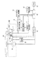
図1は本発明の実施の形態1における光ディスク装置のブロック図である。図1において、1は光源、2は対物レンズ、3はレンズホルダ、4はアクチュエータ、4aはフォーカス調整用コイル、5は四分割光検出器、6はスピンドルモータ、7はフィードモータ、8はフォーカスエラー信号生成回路、9はRF信号検出回路、10はフォーカスサーボ回路、11は信号計測回路、12はジッタ検出回路、13はメモリ、14はCPU、15はレーザ制御部、16はドライバ、50は光ディスク、100は光ヘッド部、200はピックアップモジュールである。
FIG. 1 is a block diagram of an optical disc apparatus according to
ピックアップモジュール200は、光ディスク50を回転させるスピンドルモータ6と、光ディスク50に光を照射し光ディスク50からの反射光を受光する光ヘッド部100と、光ヘッド部100を光ディスク50の半径方向に移動させるフィードモータ7を備えたフィード部と、により構成されている。
The
光ヘッド部100は、光ディスク50に照射する光を出射する光源1と、光源1からの出射光を集光する対物レンズ2と、対物レンズ2を移動可能に保持するレンズホルダ3と、レンズホルダ3を駆動するアクチュエータ4と、光ディスク50からの反射光を対物レンズ2経由で受光する四分割光検出器5を備えている。
The
アクチュエータ4は、フォーカス調整用コイル4aや図示しないチルト調整用コイルやマグネット等が設けられており、コイルに電流を流すことによりレンズホルダ3をフォーカス方向やチルト方向に駆動して対物レンズ2を移動させることで、フォーカス調整やチルト調整を行う。
The actuator 4 is provided with a
四分割光検出器5は、光ディスク50からの反射光を受光し、その受光した光量に応じた電気信号を生成し、その生成した電気信号をフォーカスエラー信号生成回路8とRF信号検出回路9とに出力する。
The
フォーカスエラー信号生成回路8は、四分割光検出器5から入力された電気信号からフォーカスエラー信号を生成し、そのフォーカスエラー信号をフォーカスサーボ回路10と信号計測回路11とに出力する。また、RF信号検出回路9は、四分割光検出器5から入力された電気信号からRF信号を検出し、そのRF信号を信号計測回路11とジッタ検出回路12とに出力する。
The focus error
フォーカスサーボ回路10は、フォーカスエラー信号生成回路8から入力されたフォーカスエラー信号を基にアクチュエータ4aに設けられたフォーカス調整用コイル4aに流す電流を決定し、CPU14に出力する。信号計測回路11は、フォーカスエラー信号生成回路8から入力されたフォーカスエラー信号の基準電圧に対する正側の振幅量と負側の振幅量を測定し、その測定結果をCPU14に出力する。また、信号計測回路11は、RF信号検出回路9から入力されたRF信号の振幅を測定し、RF信号振幅値としてCPU14に出力する。ジッタ検出回路12は、RF信号検出回路9から入力されたRF信号の時間的な揺らぎであるジッタ成分を検出し、ジッタ値としてCPU14に出力する。
The
メモリ13は、フォーカス制御の制御基準とする基準フォーカス値と、チルト制御の制御基準とする基準チルト値が格納されており、CPU14からの命令により基準フォーカス値と基準チルト値とをCPU14に送出する。この基準フォーカス値と基準チルト値は、理想的な光ディスクを使用する場合のものであり、実際の光ディスクは記録層のずれや反りがあるため、使用する光ディスク50に合わせてCPU14で調整される。
The
CPU14は、フォーカスエラー信号生成回路8、フォーカスサーボ回路10、信号計測回路11、メモリ13、ドライバ16の各部から送られる信号が入力され、これらの信号の演算処理等を行い、この演算処理の結果(信号)を各部に送出し、各部にて駆動、処理を実行させ、各部の制御を行うものである。信号計測回路11から入力されたRF信号振幅値は、その値が大きくなるほど光ディスク50に記録された情報の記録品質が良いことを意味するので、CPU14はこのRF信号振幅値を用いて光ディスク50に記録されたテストデータの記録品質の判断をすることができる。また、信号計測回路11から入力されたジッタ値は、その値が小さくなるほど光ディスク50に記録された情報の記録品質が良いことを意味するので、CPU14はこのジッタ値を用いて光ディスク50に記録されたテストデータの記録品質の判断をすることができる。
The
レーザ制御部15は、四分割光検出器5で検出した光ディスク50から反射光の光量に基づき、光ディスク50に照射する光量が所定量になるように光源1の発光量を調整する。
The
ドライバ16は、CPU14からの命令に従い、スピンドルモータ6、レーザ制御部15、フォーカス調整用コイル4aを駆動し、光ディスク50を回転させ、光源1の発光量を調整し、対物レンズ2のフォーカス制御を行う。
The
なお、本実施の形態1におけるフォーカスエラー信号生成手段はフォーカスエラー信号生成回路8、サーボ処理手段はフォーカスサーボ回路10、記憶手段はメモリ13、制御手段はCPU14に相当する。
In the first embodiment, the focus error signal generation means corresponds to the focus error
図2は、本発明の実施の形態1におけるフォーカスエラー信号生成回路を示す図である。図2において、5は四分割光検出器、5a、5bは光検出器、8はフォーカスエラー信号生成回路、8aはバランス回路、8bは差動回路である。 FIG. 2 is a diagram showing a focus error signal generation circuit according to the first embodiment of the present invention. In FIG. 2, 5 is a quadrant photodetector, 5a and 5b are photodetectors, 8 is a focus error signal generation circuit, 8a is a balance circuit, and 8b is a differential circuit.
四分割光検出器5は4つの光検出器から構成され、その4つの検出器のうち所定の検出器2つを組み合わせることにより光検出器5aと光検出器5bを形成する。光検出器5aはフォーカスエラー信号の基準電圧に対する正側の波形に対応する信号を送出し、光検出器5bはフォーカスエラー信号の基準電圧に対する負側の波形に対応する信号を送出する。ここで、基準電圧とは、光検出器5aと光検出器5bの出力信号がいずれも0である場合のフォーカスエラー信号の出力電圧を基準電圧という。
The
光検出器5aと光検出器5bとから送出された信号は、バランス回路8aを介して差動回路8bに入力され、ここで、フォーカスエラー信号の基準電圧に対する正側の波形に対応する信号と、フォーカスエラー信号の基準電圧に対する負側の波形に対応する信号とを差動演算することによりフォーカスエラー信号が生成される。
The signals sent from the
図3は、本発明の実施の形態1におけるテストデータを再生する際に生成されるフォーカスエラー信号を示す図である。図3において、横軸は合焦点時を基準としたときの対物レンズの変位量(距離)、縦軸は電圧を示しており、a1、a2、a3はフォーカスエラー信号の基準電圧に対する正側の波形の振幅量を示し、b1、b2、b3はフォーカスエラー信号の基準電圧に対する負側の波形の振幅量を示している。図3(a)は、フォーカスエラー信号の基準電圧に対する正側の波形の振幅量と負側の波形の振幅量との比率が等しい場合(a1=b1)を示し、図3(b)は、フォーカスエラー信号の基準電圧に対する正側の振幅量が負側の振幅量より大きい場合(a2>b2)を示し、図3(c)は、フォーカスエラー信号の基準電圧に対する正側の振幅量が負側の振幅量より小さい場合(a3<b3)を示している。フォーカスエラー信号は、光ディスクの記録層の位置ずれや反りの状態に応じて、図3(a)〜図3(c)のいずれかのパターンで出力される。 FIG. 3 is a diagram showing a focus error signal generated when the test data is reproduced in the first embodiment of the present invention. In FIG. 3, the horizontal axis indicates the amount of displacement (distance) of the objective lens when the focal point is the reference, the vertical axis indicates the voltage, and a1, a2, and a3 are the positive side of the reference voltage of the focus error signal. The amount of amplitude of the waveform is shown, and b1, b2, and b3 show the amount of amplitude of the negative waveform with respect to the reference voltage of the focus error signal. FIG. 3A shows a case where the ratio between the amplitude amount of the positive waveform and the amplitude amount of the negative waveform with respect to the reference voltage of the focus error signal is equal (a1 = b1), and FIG. FIG. 3C shows a case where the positive amplitude amount with respect to the reference voltage of the focus error signal is larger than the negative amplitude amount (a2> b2). FIG. 3C shows that the positive amplitude amount with respect to the reference voltage of the focus error signal is negative. The case where the amplitude amount is smaller than that on the side (a3 <b3) is shown. The focus error signal is output in one of the patterns shown in FIGS. 3A to 3C according to the position shift or warpage of the recording layer of the optical disc.
光ディスク50にデータを記録する際に用いるフォーカス制御基準値が、使用している光ディスク50の最適フォーカス制御値に近づくほど、データを再生する際に生成されるフォーカスエラー信号の基準電圧に対する正側の振幅量と負側の振幅量との差は小さくなる特性を有している。
The closer the focus control reference value used when recording data to the
これを利用した本発明の実施の形態1におけるCPU14の動作について説明する。
The operation of the
CPU14は、メモリ13から入力された基準フォーカス値を用いて、ドライバ16を介してアクチュエータ4を駆動し光ディスク50のテスト記録領域にテストデータを記録する。その後、このテストデータを再生してフォーカスエラー信号生成回路8でフォーカスエラー信号を生成し、このフォーカスエラー信号の基準電圧に対する正側の振幅量と負側の振幅量を信号計測回路11で測定する。そして、その測定結果に基づいて、基準フォーカス値に所定値を加算した第1修正フォーカス値と、メモリ13から入力された基準フォーカス値から所定値を減算した第2修正フォーカス値を算出する。
The
なお、本実施の形態1においては、基準フォーカス値を用いたテストデータの記録の後に第1修正フォーカス値と、第2修正フォーカス値の算出を行ったが、第1修正フォーカス値と、第2修正フォーカス値の算出は、基準フォーカス値を用いたテストデータの記録の前に予め行っても良い。 In the first embodiment, the first corrected focus value and the second corrected focus value are calculated after the test data is recorded using the reference focus value. However, the first corrected focus value and the second corrected focus value are calculated. The correction focus value may be calculated in advance before recording the test data using the reference focus value.
このとき、図3(a)に示すように、フォーカスエラー信号の基準電圧に対する正側の振幅量と負側の振幅量との比率が等しい場合、テストデータを記録する際に用いた基準フォーカス値が、使用する光ディスク50に対して適正であると判断する。そして、使用する光ディスク50の個体状況に応じたフォーカス制御基準値を算出するのに充分な情報が得られたと判断して基準フォーカス値によるテスト記録以降のテスト記録を中止する。これにより、使用する個体状況に応じたフォーカス制御基準値を算出する際に、精度向上が見込めないテスト記録を排除するので、フォーカス制御基準値算出にかかる時間を最小限に抑えることができる。ここで、フォーカスエラー信号の基準電圧に対する正側の振幅量と負側の振幅量との差が所定量未満の場合も正側の振幅量と負側の振幅量との比率が等しいと判断することにより、CPU14がフォーカスエラー信号の正側の振幅と負側の振幅との比率を判別する際の判別精度を高めるので、使用する個体状況に応じたフォーカス制御の制御基準値を算出するのに充分な情報が得られたか否かを精度良く判断できる。本実施の形態1における所定量は、フォーカスエラー信号振幅量の20%である。
At this time, as shown in FIG. 3A, when the ratio of the positive amplitude amount and the negative amplitude amount to the reference voltage of the focus error signal is equal, the reference focus value used when recording the test data Is determined to be appropriate for the
また、図3(b)に示したように、フォーカスエラー信号の基準電圧に対する正側の振幅量が負側の振幅量より大きい場合、テストデータの記録に用いた基準フォーカス値が、使用する光ディスク50に対して適正でなく、フォーカス制御が可能なフォーカス値とチルト値の関係を示す分布の端の方に位置していると判断する。そして、基準フォーカス値によるテスト記録が最適記録条件から離れた条件であると判断して更に最適記録条件から離れると予想される第2修正フォーカス値を用いたテスト記録を行わないので、記録したテストデータを再生する際にフォーカス制御ができず、記録したテストデータを再生できなくなる確率を低く抑え、記録したテストデータを再生して得られる情報の一部が欠落して最適フォーカス制御基準値を算出する処理を正常に行えず、最適フォーカス制御基準値が充分な精度を得られない、もしくは記録したテストデータを再生するとき予期せぬ情報の欠落が起こり最適フォーカス制御基準値を算出する処理自体が中断することを回避できる。ここで、フォーカスエラー信号の基準電圧に対する正側の振幅量と負側の振幅量との差が所定値以上の場合、正側の振幅量が負側の振幅量より大きいと判断することにより、CPU14がフォーカスエラー信号の正側の振幅を負側の振幅より大きいと判別する際の判別精度を高めるので、第2修正フォーカス値を用いたテスト記録を行う必要があるか否かの判断を精度良く行うことができる。
Further, as shown in FIG. 3B, when the positive amplitude amount with respect to the reference voltage of the focus error signal is larger than the negative amplitude amount, the reference focus value used for recording the test data is the optical disc to be used. 50 is not appropriate, and it is determined that it is located toward the end of the distribution indicating the relationship between the focus value and the tilt value for which focus control is possible. Since the test recording using the reference focus value is determined to be a condition away from the optimum recording condition, the test recording using the second corrected focus value that is expected to be further away from the optimum recording condition is not performed. The focus control cannot be performed when data is played back, and the probability that the recorded test data cannot be played back is kept low, and some of the information obtained by playing back the recorded test data is lost, and the optimal focus control reference value is calculated. The process of calculating the optimal focus control reference value is not possible when the optimal focus control reference value cannot obtain sufficient accuracy, or when the recorded test data is reproduced, an unexpected loss of information occurs. The interruption can be avoided. Here, when the difference between the positive-side amplitude amount and the negative-side amplitude amount with respect to the reference voltage of the focus error signal is a predetermined value or more, by determining that the positive-side amplitude amount is larger than the negative-side amplitude amount, The
また、図3(c)に示したように、フォーカスエラー信号の基準電圧に対する正側の振幅量が負側の振幅量より小さい場合、図3(b)の場合と同様に、テストデータの記録に用いた基準フォーカス値が、使用する光ディスク50に対して適正でなく、フォーカス制御が可能なフォーカス値とチルト値の関係を示す分布の端の方に位置していると判断する。そして、基準フォーカス値によるテスト記録が最適記録条件から離れた条件であると判断して更に最適記録条件から離れると予想される第1修正フォーカス値を用いたテスト記録を行わないので、記録したテストデータを再生する際にフォーカス制御ができず、記録したテストデータを再生できなくなる確率を低く抑え、記録したテストデータを再生して得られる情報の一部が欠落して最適フォーカス制御基準値を算出する処理を正常に行えず、最適フォーカス制御基準値が充分な精度を得られない、もしくはテストデータを再生するとき予期せぬ情報の欠落が起こり最適フォーカス制御基準値を算出する処理自体が中断することを回避できる。ここで、フォーカスエラー信号の基準電圧に対する正側の振幅量と負側の振幅量との差が所定値以上の場合、正側の振幅量が負側の振幅量より小さいと判断することにより、CPU14がフォーカスエラー信号の正側の振幅を負側の振幅より小さいと判別する際の判別精度を高めるので、第1修正フォーカス値を用いたテスト記録を行う必要があるか否かの判別を精度良く行うことができる。
Further, as shown in FIG. 3C, when the positive-side amplitude amount with respect to the reference voltage of the focus error signal is smaller than the negative-side amplitude amount, the test data is recorded as in FIG. It is determined that the reference focus value used in the above is not appropriate for the
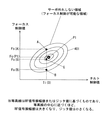
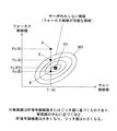
図4〜図6は、本発明の実施の形態1におけるフォーカス制御基準値を選択する方法を示す図であり、フォーカス制御が可能なフォーカス制御値とチルト制御値の組み合わせの範囲を示している。いずれも記録層の位置ずれや反りがある光ディスクを使用する場合の一例を示している。図4〜図6において、401〜403は領域であり、横軸はチルト制御値、縦軸はフォーカス制御値を示す。また、Fo(G)は光ディスク装置のメモリに予め記憶されている基準フォーカス値、Ti(0)は光ディスク装置のメモリに予め記憶されている基準チルト値、Fo(P1)は図4に示す光ディスクを使用する際の最適なフォーカス制御基準値、Fo(P2)は図5に示す光ディスクを使用する際に最適なフォーカス制御基準値、Fo(P3)は図6に示す光ディスクを使用する際に最適なフォーカス制御基準値である。
4 to 6 are diagrams showing a method for selecting a focus control reference value according to the first embodiment of the present invention, and show a range of combinations of focus control values and tilt control values capable of focus control. In either case, an example of using an optical disk having a recording layer misalignment or warpage is shown. 4 to 6,
フォーカス制御値とチルト制御値は、その組み合わせによりフォーカスサーボ外れしない組み合わせとフォーカスサーボ外れする組み合わせがある。すなわち、フォーカス制御可能な組み合わせとフォーカス制御困難な組み合わせがある。 Depending on the combination of the focus control value and the tilt control value, there are a combination that does not deviate the focus servo and a combination that deviates the focus servo. That is, there are combinations that allow focus control and combinations that make focus control difficult.
図4〜図6は、その組み合わせを示したものであり、領域401〜領域403の範囲内がフォーカス制御可能な組み合わせであり、領域401〜領域403の範囲外がフォーカス制御困難な組み合わせである。領域401〜領域403内にある複数の楕円領域はフォーカスサーボのサーボ可能状況を示す等高線であり、中心部にいくほどその光ディスクに最適なフォーカス制御基準値とチルト制御基準値の組み合わせになる。
FIG. 4 to FIG. 6 show the combinations. The combinations in the
光ディスク装置は、対物レンズ2を光ディスク50に対してフォーカス制御する際の基準フォーカス値Fo(G)をメモリ13に記憶している。この基準フォーカス値Fo(G)を中心に、光ディスクの状態に合わせてフォーカス制御基準値を変更することにより、記録品質の向上を図っている。光ディスクの記録層の位置や光ディスクの反りは実使用上では直接計測することができないので、使用する光ディスクに対して対物レンズの位置を変化させながら複数のテストデータを記録し、その記録したテストデータを再生し、RF信号振幅値またはジッタ値をチェックすることで、テストデータの記録に用いた条件の中から使用する光ディスクの記録品質が最良になる条件を選択し、対物レンズの位置を決定している。
The optical disk apparatus stores a reference focus value Fo (G) in the
本実施の形態1におけるテストデータの記録は、メモリ13に記憶されている基準フォーカス値Fo(G)と、基準フォーカス値Fo(G)に所定値を加算した第1修正フォーカス値Fo(A)と、基準フォーカス値Fo(G)から所定値を減算した第2修正フォーカス値Fo(B)を算出し、これら3つのフォーカス値のうちからテストデータの記録を行うフォーカス値を決定する。
The test data is recorded in the first embodiment by the reference focus value Fo (G) stored in the
3つのフォーカス値のうちからどれを選択するかは、使用する光ディスク50の状態により異なるので、以下順に説明する。
Which of the three focus values is selected depends on the state of the
まず、使用する光ディスクに記録層の位置ずれや反りがほとんど無い場合である。この場合、記録品質が最良になるフォーカス制御値とチルト制御値の関係は、例えば図4に示す点P1になる。このときのテストデータを記録するフォーカス制御値の決定方法は、以下の流れになる。 First, there is a case where there is almost no displacement or warping of the recording layer in the optical disc to be used. In this case, the relationship between the focus control value and the tilt control value that provides the best recording quality is, for example, a point P1 shown in FIG. The method for determining the focus control value for recording the test data at this time is as follows.
メモリ13に記憶された基準フォーカス値Fo(G)をCPU14がフォーカス制御基準値に設定し、メモリ13に記憶された基準チルト値Ti(0)をCPU14がチルト制御の基準値に設定して、テストデータを記録する。このとき、図4に示す特性を持つ光ディスクに対しては、点Gに示す基準フォーカス値Fo(G)でテストデータを記録することになる。
The
この場合、テストデータを再生する際に生成されるフォーカスエラー信号は図3(a)に示すものと略同一になり、フォーカスエラー信号の正側の振幅量と負側の振幅量との比率が等しくなるので、点Gに示すフォーカス値Fo(G)が点P1に示すフォーカス値Fo(P1)と略同一値になっていると判定する。そして、点Aに示す第1修正フォーカス値Fo(A)によるテストデータの記録と点Bに示す第2修正フォーカス値Fo(B)によるテストデータの記録を行わず、点Gに示す基準フォーカス値Fo(G)のみを用いて以降の処理を行う。 In this case, the focus error signal generated when the test data is reproduced is substantially the same as that shown in FIG. 3A, and the ratio between the positive amplitude amount and the negative amplitude amount of the focus error signal is Therefore, it is determined that the focus value Fo (G) indicated by the point G is substantially the same value as the focus value Fo (P1) indicated by the point P1. Then, the test data is recorded by the first corrected focus value Fo (A) indicated by the point A and the test data is not recorded by the second corrected focus value Fo (B) indicated by the point B, and the reference focus value indicated by the point G is obtained. Subsequent processing is performed using only Fo (G).
このように、第1修正フォーカス値Fo(A)及び第2修正フォーカス値Fo(B)を用いず、基準フォーカス値Fo(G)のみを用いてテストデータの記録を行うことにより、複数のテストデータを記録することにより光ディスクの最適フォーカス制御基準値を算出する処理において、基準フォーカス値Fo(G)によるテスト記録のみで、使用する光ディスク50の個体状況に応じたフォーカス制御基準値を算出するのに充分な情報が得られたと判断して基準フォーカス値Fo(G)によるテスト記録以降のテスト記録を中止するので、使用する個体状況に応じた最適フォーカス制御基準値を算出する際に、精度向上が見込めないテスト記録を排除できる。その結果、使用する個体状況に応じた最適フォーカス制御基準値を算出する際に、精度向上が見込めないテスト記録を排除するので、フォーカス制御基準値算出にかかる時間を最小限に抑えることができる。
As described above, the test data is recorded using only the reference focus value Fo (G) without using the first correction focus value Fo (A) and the second correction focus value Fo (B). In the process of calculating the optimum focus control reference value of the optical disc by recording data, the focus control reference value corresponding to the individual situation of the
また、CPU14が、フォーカスエラー信号の正側の振幅量と負側の振幅量との差が所定量未満の場合、正側の振幅量と負側の振幅量との比率が等しいと判断することによって、CPU14がフォーカスエラー信号の正側の振幅と負側の振幅との比率を判別する際の判別精度を高めるので、使用する光ディスク50の個体状況に応じた最適フォーカス制御基準値を算出するのに充分な情報が得られたか否かを精度良く判断できる。ここで、本実施の形態における所定値は、フォーカスエラー信号全体の振幅値の20%を所定値とした。
Further, when the difference between the positive amplitude amount and the negative amplitude amount of the focus error signal is less than a predetermined amount, the
次に、使用する光ディスクに記録層の位置ずれや反りがある場合である。記録品質が最良になるフォーカス値とチルト値の関係は、例えば図5に示す点P2や図6に示す点P3になる。このときのテストデータを記録するフォーカス値の決定方法は、以下の流れになる。 Next, there is a case where the recording layer is misaligned or warped in the optical disk to be used. The relationship between the focus value and the tilt value that provides the best recording quality is, for example, a point P2 shown in FIG. 5 and a point P3 shown in FIG. The method for determining the focus value for recording the test data at this time is as follows.
図5の場合、CPU14がメモリ13に記憶された基準フォーカス値Fo(G)をフォーカス制御基準値に設定し、メモリ13に記憶された基準チルト値Ti(0)をチルト制御基準値に設定して、テストデータを記録する。このとき、図5に示す特性を持つ光ディスクに対しては、点Gに示す基準フォーカス値Fo(G)でテストデータを記録することになる。この場合、テストデータを再生する際に生成されるフォーカスエラー信号は図3(b)に示すものになり、フォーカスエラー信号の正側の振幅量が負側の振幅量より大きくなるので、点Gに示すフォーカス値Fo(G)が点P2に示すフォーカス値Fo(P2)と異なっていると判断する。併せて、点Bに示す第2修正フォーカス値Fo(B)によるテストデータの記録を行うと、フォーカスエラー信号の正側の振幅量が負側の振幅量より更に大きくなると判断する。そして、点Bに示す第2修正フォーカス値Fo(B)によるテストデータの記録を行わず、点Aに示す第1修正フォーカス値Fo(A)を用いて以降の処理を行う。
In the case of FIG. 5, the
このように、第2修正フォーカス値Fo(B)を用いず、基準フォーカス値Fo(G)の代わりに第1修正フォーカス値Fo(A)を用いてテストデータの記録を行うことにより、複数のテストデータを記録することにより光ディスクの最適フォーカス制御基準値を算出する処理において、基準フォーカス値Fo(G)によるテスト記録が最適記録条件から離れた条件であると判断して更に最適記録条件から離れると予想される第2修正フォーカス値Fo(B)を用いたテスト記録を行わないので、記録したテストデータを再生する際にフォーカス制御ができず、記録したテストデータを再生できなくなる確率を低く抑え、記録したテストデータを再生して得られる情報の一部が欠落して最適フォーカス制御基準値を算出する処理を正常に行えず、最適フォーカス制御基準値が充分な精度を得られない、もしくはテストデータを再生するとき予期せぬ情報の欠落が起こり最適フォーカス制御基準値を算出する処理自体が中断することを回避できる。 As described above, the test data is recorded by using the first corrected focus value Fo (A) instead of the second corrected focus value Fo (B) and using the first corrected focus value Fo (A). In the process of calculating the optimum focus control reference value of the optical disc by recording the test data, it is determined that the test recording with the reference focus value Fo (G) is a condition away from the optimum recording condition, and further away from the optimum recording condition. Since the test recording using the second corrected focus value Fo (B) that is expected to be performed is not performed, the focus control cannot be performed when the recorded test data is reproduced, and the probability that the recorded test data cannot be reproduced is kept low. When the recorded test data is reproduced, some of the information obtained is lost and the process of calculating the optimum focus control reference value is performed normally. It not, can be avoided optimum focus control reference value is not obtained a sufficient accuracy, or the processing itself missing unexpected information to calculate the optimum focus control reference value occurs when reproducing the test data interruption.
また、CPU14が、正側の振幅量と負側の振幅量との差が所定量以上の場合、正側の振幅量が負側の振幅量より大きいと判断することによって、CPU14がフォーカスエラー信号の正側の振幅を負側の振幅より大きいと判別する際の判別精度を高めるので、第2修正フォーカス値Fo(B)を用いたテスト記録を行う必要があるか否かの判断を精度良く行うことができる。ここで、本実施の形態における所定値は、フォーカスエラー信号全体の振幅値の20%を所定値とした。
Further, when the difference between the positive amplitude amount and the negative amplitude amount is equal to or larger than a predetermined amount, the
次に、図6の場合、CPU14がメモリ13に記憶された基準フォーカス値Fo(G)をフォーカス制御基準値に設定し、メモリ13に記憶された基準チルト値Ti(0)をチルト制御の基準値に設定して、テストデータを記録する。このとき、図6に示す特性を持つ光ディスクに対しては、点Gに示す基準フォーカス値Fo(G)でテストデータを記録することになる。この場合、テストデータを再生する際に生成されるフォーカスエラー信号は図3(c)に示すものになり、フォーカスエラー信号の正側の振幅量が負側の振幅量より小さくなるので、点Gに示すフォーカス値Fo(G)が点P3に示すフォーカス値Fo(P3)と異なっていると判断する。併せて、点Aに示す第1修正フォーカス値Fo(A)によるテストデータの記録を行うと、フォーカスエラー信号の正側の振幅量が負側の振幅量より更に小さくなると判断する。そして、点Aに示す第1修正フォーカス値Fo(A)によるテストデータの記録を行わず、点Bに示す第2修正フォーカス値Fo(B)を用いて以降の処理を行う。
Next, in the case of FIG. 6, the
このように、第1修正フォーカス値Fo(A)を用いず、基準フォーカス値Fo(G)の代わりに第2修正フォーカス値Fo(B)を用いてテストデータの記録を行うことにより、複数のテストデータを記録することにより光ディスクの最適フォーカス制御基準値を算出する処理において、基準フォーカス値Fo(G)によるテスト記録が最適記録条件から離れた条件であると判断して更に最適記録条件から離れると予想される第1修正フォーカス値Fo(A)を用いたテスト記録を行わないので、記録したテストデータを再生する際にフォーカス制御ができず、記録したテストデータを再生できなくなる確率を低く抑え、記録したテストデータを再生して得られる情報の一部が欠落して最適フォーカス制御基準値を算出する処理を正常に行えず、最適フォーカス制御基準値が充分な精度を得られない、もしくはテストデータを再生するとき予期せぬ情報の欠落が起こり最適フォーカス制御基準値を算出する処理自体が中断することを回避できる。 As described above, the test data is recorded by using the second correction focus value Fo (B) instead of the first correction focus value Fo (A) and using the second correction focus value Fo (B) instead of the reference focus value Fo (G). In the process of calculating the optimum focus control reference value of the optical disc by recording the test data, it is determined that the test recording with the reference focus value Fo (G) is a condition away from the optimum recording condition, and further away from the optimum recording condition. Since the test recording using the first corrected focus value Fo (A) that is expected to be performed is not performed, the focus control cannot be performed when the recorded test data is reproduced, and the probability that the recorded test data cannot be reproduced is kept low. When the recorded test data is reproduced, some of the information obtained is lost and the process of calculating the optimum focus control reference value is performed normally. It not, can be avoided optimum focus control reference value is not obtained a sufficient accuracy, or the processing itself missing unexpected information to calculate the optimum focus control reference value occurs when reproducing the test data interruption.
また、CPU14が、正側の振幅量と負側の振幅量との差が所定量以上の場合、正側の振幅量が負側の振幅量より小さいと判断することによって、CPU14がフォーカスエラー信号の正側の振幅を負側の振幅より大きいと判別する際の判別精度を高めるので、第1修正フォーカス値Fo(A)を用いたテスト記録を行う必要があるか否かの判断を精度良く行うことができる。ここで、本実施の形態における所定値は、フォーカスエラー信号全体の振幅値の20%を所定値とした。
Further, when the difference between the positive amplitude amount and the negative amplitude amount is equal to or larger than a predetermined amount, the
図7は、本発明の実施の形態1におけるフォーカス制御方法を示すフローチャートである。
FIG. 7 is a flowchart showing the focus control method in
光ディスク装置に光ディスク50が装着されると、CPU14はドライバ15を介してスピンドルモータ6を回転させ、ドライバ16、レーザ制御部15を介して光源1を発光させる(S1)。次に、CPU14は、メモリ13から基準チルト値Ti(0)と基準フォーカス値Fo(G)を読み出し(S2)、基準チルト値Ti(0)と基準フォーカス値Fo(G)に基づきテストデータを記録する(S3)。その後、CPU14は基準チルト値Ti(0)と基準フォーカス値Fo(G)に基づき記録したテストデータを再生し(S4)、その再生信号を基にフォーカスエラー信号生成回路8でフォーカスエラー信号を生成する(S5)。生成されたフォーカスエラー信号は、信号計測回路11に送られ、信号計測回路11でフォーカスエラー信号の基準電圧に対する正側の振幅量と負側の振幅量とを比較する(S6)。
When the
このとき、フォーカスエラー信号の基準電圧に対する正側の振幅量と負側の振幅量との比率が比較され、図3(a)に示すように、正側の振幅量と負側の振幅量との比率が等しい場合には(S7)、テストデータの記録に用いた基準フォーカス値Fo(G)が、装着した光ディスクに対して適性であると判断し、使用する光ディスクの個体状況に応じたフォーカス制御基準値を算出するのに充分な情報が得られたと判断して、以降のテストデータの記録を行わない(S8)。これにより、使用する個体状況に応じたフォーカス制御基準値を算出する際に、精度向上が見込めないテスト記録を排除するので、フォーカス制御基準値算出にかかる時間を最小限に抑えることができる。 At this time, the ratio of the positive amplitude amount to the negative amplitude amount with respect to the reference voltage of the focus error signal is compared, and as shown in FIG. 3A, the positive amplitude amount and the negative amplitude amount are Are equal (S7), it is determined that the reference focus value Fo (G) used for recording the test data is appropriate for the mounted optical disc, and the focus according to the individual situation of the optical disc to be used is determined. It is determined that sufficient information has been obtained to calculate the control reference value, and subsequent test data is not recorded (S8). Thereby, when calculating the focus control reference value according to the individual situation to be used, test recordings that cannot be expected to improve accuracy are eliminated, so that the time required for calculating the focus control reference value can be minimized.
また、フォーカスエラー信号の基準電圧に対する正側の振幅量と負側の振幅量との比率が比較され、正側の振幅量と負側の振幅量との比率が等しくなく、正側の振幅量が負側の振幅量より大きい場合には(S9)、基準フォーカス値Fo(G)に所定値を加算した第1修正フォーカス値Fo(A)を算出する(S10)。そして、テストデータの記録に用いた基準フォーカス値Fo(G)が、使用する光ディスクに対して適正でなく、フォーカス制御が可能なフォーカス制御値とチルト制御値の関係を示す分布の端の方に位置していると判断し、基準フォーカス値Fo(G)によるテスト記録が最適記録条件から離れた位置にあると判断して更に最適記録条件から離れると予想される第2修正フォーカス値Fo(B)を用いたテスト記録を行わず、最適記録条件に近づくと予想される基準チルト値Ti(0)と第1修正フォーカス値Fo(A)の組み合わせでテスト記録を行う(S11)。これにより、基準フォーカス値Fo(G)によるテスト記録が最適記録条件から離れた条件であると判断して更に最適記録条件から離れると予想される第2修正フォーカス値Fo(B)を用いたテスト記録を行わないので、記録したテストデータを再生する際にフォーカス制御ができず、記録したテストデータを再生できなくなる確率を低く抑え、記録したテストデータを再生して得られる情報の一部が欠落して最適フォーカス制御基準値を算出する処理を正常に行えず、最適フォーカス制御基準値が充分な精度を得られない、もしくは記録したテストデータを再生するとき予期せぬ情報の欠落が起こり最適フォーカス制御基準値を算出する処理自体が中断することを回避できる。 In addition, the ratio of the positive amplitude amount to the negative amplitude amount with respect to the reference voltage of the focus error signal is compared, and the ratio of the positive amplitude amount to the negative amplitude amount is not equal, and the positive amplitude amount. Is larger than the negative amplitude amount (S9), a first corrected focus value Fo (A) obtained by adding a predetermined value to the reference focus value Fo (G) is calculated (S10). The reference focus value Fo (G) used for recording the test data is not appropriate for the optical disc to be used, and is closer to the end of the distribution indicating the relationship between the focus control value and the tilt control value that can be controlled. The second corrected focus value Fo (B, which is predicted to be further away from the optimum recording condition by judging that the test recording is based on the reference focus value Fo (G) is at a position away from the optimum recording condition. The test recording is performed with a combination of the reference tilt value Ti (0) and the first corrected focus value Fo (A) that is expected to approach the optimum recording condition without performing the test recording using () (S11). As a result, the test using the second corrected focus value Fo (B) that is predicted to be further away from the optimum recording condition by judging that the test recording with the reference focus value Fo (G) is away from the optimum recording condition. Since recording is not performed, focus control cannot be performed when the recorded test data is reproduced, and the probability that the recorded test data cannot be reproduced is kept low, and a part of the information obtained by reproducing the recorded test data is missing. Therefore, the process of calculating the optimum focus control reference value cannot be performed normally, and the optimum focus control reference value cannot obtain a sufficient accuracy, or an unexpected loss of information occurs when the recorded test data is played back. It is possible to avoid interruption of the processing itself for calculating the control reference value.
また、フォーカスエラー信号の基準電圧に対する正側の振幅量と負側の振幅量との比率が比較され、正側の振幅量と負側の振幅量との比率が等しくなく、正側の振幅量が負側の振幅量より大きくなく、正側の振幅量が負側の振幅量より小さい場合には(S12)、基準フォーカス値Fo(G)から所定値を減算した第2修正フォーカス値Fo(B)を算出する(S13)。そして、テストデータの記録に用いた基準フォーカス値Fo(G)が、使用する光ディスク50に対して適正でなく、フォーカス制御が可能なフォーカス値とチルト値の関係を示す分布の端の方に位置していると判断し、基準フォーカス値Fo(G)によるテスト記録が最適記録条件から離れた位置にあると判断して更に最適記録条件から離れると予想される第1修正フォーカス値Fo(A)を用いたテスト記録を行わず、最適記録条件に近づくと予想される基準チルト値Ti(0)と第2修正フォーカス値Fo(B)の組み合わせでテストデータの記録を行う(S14)。これにより、基準フォーカス値Fo(G)によるテスト記録が最適記録条件から離れた条件であると判断して更に最適記録条件から離れると予想される第1修正フォーカス値Fo(A)を用いたテスト記録を行わないので、記録したテストデータを再生する際にフォーカス制御ができず、記録したテストデータを再生できなくなる確率を低く抑え、記録したテストデータを再生して得られる情報の一部が欠落して最適フォーカス制御基準値を算出する処理を正常に行えず、最適フォーカス制御基準値が充分な精度を得られない、もしくは記録したテストデータを再生するとき予期せぬ情報の欠落が起こり最適フォーカス制御基準値を算出する処理自体が中断することを回避できる。
In addition, the ratio of the positive amplitude amount to the negative amplitude amount with respect to the reference voltage of the focus error signal is compared, and the ratio of the positive amplitude amount to the negative amplitude amount is not equal, and the positive amplitude amount. Is not larger than the negative-side amplitude amount, and the positive-side amplitude amount is smaller than the negative-side amplitude amount (S12), the second corrected focus value Fo () obtained by subtracting a predetermined value from the reference focus value Fo (G) B) is calculated (S13). Then, the reference focus value Fo (G) used for recording the test data is not appropriate for the
以上の内容のように、複数のテストデータを記録することにより光ディスクの最適フォーカス制御基準値を算出する処理において、基準フォーカス値Fo(G)によるテスト記録以降のテスト記録にフォーカス制御ができずテストデータを再生できなくなるテスト記録をしないので、記録したテストデータを再生して得られる情報の一部が欠落して最適フォーカス制御基準値を算出する処理を正常に行えず、最適フォーカス制御基準値が充分な精度を得られない、もしくは記録したテストデータを再生して得られる情報の一部が欠落することにより最適フォーカス制御基準値を算出する処理自体が中断することを回避できる。その結果、記録層の位置ずれや反りが大きい光ディスクを使用する場合であっても、そのずれ分やそり分を考慮して、使用する光ディスクに最適な対物レンズの位置を算出できる光ディスク装置及びそのフォーカス制御方法を実現できる。 As described above, in the process of calculating the optimum focus control reference value of the optical disc by recording a plurality of test data, the focus control cannot be performed in the test recording after the test recording with the reference focus value Fo (G). Since the test recording that prevents the data from being reproduced is not performed, a part of the information obtained by reproducing the recorded test data is lost, and the process for calculating the optimum focus control reference value cannot be performed normally. It can be avoided that the process itself for calculating the optimum focus control reference value is interrupted due to lack of sufficient accuracy or lack of a part of information obtained by reproducing the recorded test data. As a result, an optical disc apparatus capable of calculating the optimum position of the objective lens for the optical disc to be used in consideration of the deviation and warpage even when using an optical disc with a large positional deviation and warpage of the recording layer, and its A focus control method can be realized.
また、基準フォーカス値Fo(G)に基づいてテストデータを記録し、このテストデータを再生する際に生成されるフォーカスエラー信号の基準電圧に対する正側の振幅量と負側の振幅量との比率に基づいて、基準フォーカス値Fo(G)、第1修正フォーカス値Fo(A)及び第2修正フォーカス値Fo(B)のうちいずれかを用いてテストデータの記録を行うかを判断することによって、複数のテストデータを記録することにより光ディスクの最適フォーカス制御基準値を算出する処理において、基準フォーカス値Fo(G)により記録したテストデータを再生することにより得られる情報から基準フォーカス値Fo(G)によるテスト記録以降のテスト記録回数を決定するので、使用する光ディスクの個体状況に応じた最適フォーカス制御基準値を算出する精度を向上でき、併せて精度向上が見込めないテスト記録を排除できる。その結果、使用する光ディスク50の個体状況に応じた最適フォーカス制御基準値を算出する精度を向上し、併せて精度向上が見込めないテスト記録を排除するので、使用する光ディスク50の個体状況に応じた最適フォーカス制御基準値を算出する精度を高めつつ、フォーカス制御基準値算出にかかる時間を最小限に抑えることができる光ディスク装置及びそのフォーカス制御を実現できる。
Further, the ratio of the positive amplitude amount to the negative amplitude amount with respect to the reference voltage of the focus error signal generated when the test data is recorded based on the reference focus value Fo (G) and reproduced. Based on the reference focus value Fo (G), the first correction focus value Fo (A), and the second correction focus value Fo (B). In the process of calculating the optimum focus control reference value of the optical disc by recording a plurality of test data, the reference focus value Fo (G (G) is obtained from information obtained by reproducing the test data recorded with the reference focus value Fo (G). ), The number of test recordings after the test recording is determined, so the optimum focus according to the individual situation of the optical disk to be used Can improve the accuracy of calculating the control reference value, it can be eliminated test recording that are not expected to be accuracy together. As a result, the accuracy of calculating the optimum focus control reference value according to the individual situation of the
(実施の形態2)
本発明の実施の形態2は、第1基準フォーカス値と第1基準チルト値の組み合わせと、第2基準フォーカス値と第2基準チルト値の組み合わせとを用いる方法について図面を参照しながら説明する。
(Embodiment 2)
In the second embodiment of the present invention, a method using a combination of a first reference focus value and a first reference tilt value and a combination of a second reference focus value and a second reference tilt value will be described with reference to the drawings.
本実施の形態2における光ディスク装置の全体構成は、図1、図2に示す実施の形態1と同様である。また、本実施の形態2におけるテストデータを再生する際に生成されるフォーカスエラー信号は図3に示す実施の形態1と同様であり、光ディスクの記録層の位置ずれや反りの状態に応じて、図3(a)〜図3(c)のいずれかのパターンで出力される。 The overall configuration of the optical disc apparatus according to the second embodiment is the same as that of the first embodiment shown in FIGS. Further, the focus error signal generated when reproducing the test data in the second embodiment is the same as that of the first embodiment shown in FIG. The pattern is output in any one of FIGS. 3A to 3C.
なお、本実施の形態2におけるフォーカスエラー信号生成手段は図1に示すフォーカスエラー信号生成回路8、サーボ処理手段はフォーカスサーボ回路10、記憶手段はメモリ13、制御手段はCPU14に相当する。
The focus error signal generating means in the second embodiment corresponds to the focus error
図8〜図10は、本発明の実施の形態2におけるフォーカス制御基準値を選択する方法を示す図であり、フォーカス制御が可能なフォーカス制御値とチルト制御値の組み合わせの範囲を示している。いずれも記録層の位置ずれや反りがある光ディスクを使用する場合の一例を示している。図8〜図10において、404〜406は領域であり、横軸はチルト制御値であり、縦軸はフォーカス制御値を示す。また、Fo(H)は光ディスク装置のメモリに予め記憶されている第1基準フォーカス値、Ti(1)は光ディスク装置のメモリに予め記憶されている第1基準チルト値、Fo(I)は光ディスク装置のメモリに予め記憶されている第2基準フォーカス値、Ti(2)は光ディスク装置のメモリに予め記憶されている第2基準チルト値、Fo(P1)は図8に示す光ディスクを使用する際の最適なフォーカス制御基準値、Fo(P2)は図9に示す光ディスクを使用する際に最適なフォーカス制御基準値、Fo(P3)は図10に示す光ディスクを使用する際に最適なフォーカス制御基準値である。
FIGS. 8 to 10 are diagrams showing a method for selecting a focus control reference value according to the second embodiment of the present invention, and show a range of combinations of focus control values and tilt control values capable of focus control. In either case, an example of using an optical disk having a recording layer misalignment or warpage is shown. 8 to 10,
フォーカス制御値とチルト制御値は、その組み合わせによりフォーカスサーボ外れしない組み合わせとフォーカスサーボ外れする組み合わせがある。すなわち、フォーカス制御可能な組み合わせとフォーカス制御困難な組み合わせがある。 Depending on the combination of the focus control value and the tilt control value, there are a combination that does not deviate the focus servo and a combination that deviates the focus servo. That is, there are combinations that allow focus control and combinations that make focus control difficult.
図8〜図10は、その組み合わせを示したものであり、領域404〜領域406の範囲内がフォーカス制御可能な組み合わせであり、領域404〜領域406の範囲外がフォーカス制御困難な組み合わせである。領域404〜領域406内にある複数の楕円領域はフォーカスサーボのサーボ可能状況を示す等高線であり、中心部にいくほどその光ディスクに最適なフォーカス制御基準値とチルト制御基準値の組み合わせになる。
FIG. 8 to FIG. 10 show such combinations. In the range from the
光ディスク装置は、対物レンズ2を光ディスク50に対してフォーカス制御する際の基準となる基準フォーカス値をメモリ13に記憶している。この基準フォーカス値を中心に、それぞれの光ディスク50に合わせてフォーカス制御の基準値を変更することにより、記録品質の向上を図っている。光ディスクの記録層の位置や光ディスクの反りは実使用上では直接計測することができないので、使用する光ディスク50に対物レンズ2の位置を変化させながら複数のテストデータを記録し、その記録されたテストデータを再生し、一定のチェック処理を行うことで、テストデータの記録に用いた条件の中から使用する光ディスクの記録品質が最良になる条件を選択し、対物レンズ2の位置を決定している。
The optical disc apparatus stores a reference focus value, which serves as a reference for controlling the focus of the
本実施の形態2におけるテストデータの記録は、メモリ13に記憶されている第1基準フォーカス値Fo(H)と、第1基準フォーカス値Fo(H)に所定値を加算した第1修正フォーカス値Fo(C)と、第1基準フォーカス値Fo(H)から所定値を減算した第2修正フォーカス値Fo(D)を算出し、これら3つのフォーカス値のうちからテストデータの記録を行うフォーカス値を決定し、決定したフォーカス値と第1基準チルト値Ti(1)との組み合わせによりテストデータの記録を行う。また、メモリ13に記憶されている第2基準フォーカス値Fo(I)と、第2基準フォーカス値Fo(I)に所定値を加算した第3修正フォーカス値Fo(E)と、第2基準フォーカス値Fo(I)から所定値を減算した第4修正フォーカス値Fo(F)を算出し、これら3つのフォーカス値のうちからテストデータの記録を行うフォーカス値を決定し、決定したフォーカス値と第2基準チルト値Ti(2)との組み合わせによりテストデータの記録を行う。
The test data is recorded in the second embodiment in the first reference focus value Fo (H) stored in the
それぞれ3つのフォーカス値のうちからどれを選択するかは、使用する光ディスクの状態により異なるので、以下順に説明する。 Which one of the three focus values is selected depends on the state of the optical disk to be used, and will be described in the following order.
まず、使用する光ディスク50に記録層の位置ずれや反りがほとんど無い場合である。この場合、記録品質が最良になるフォーカス制御値とチルト制御値の関係は、例えば図8に示す点P1になる。このときのテストデータを記録するフォーカス値の決定方法は、以下の流れになる。
First, there is a case where there is almost no displacement or warping of the recording layer in the
メモリ13に記憶された第1基準フォーカス値Fo(H)をフォーカス制御の基準値に設定し、メモリ13に記憶された第1基準チルト値Ti(1)をチルト制御の基準値に設定してテストデータを記録し、更にメモリ13に記憶された第2基準フォーカス値Fo(I)をフォーカス制御の基準値に設定し、メモリ13に記憶された第2基準チルト値Ti(2)をチルト制御の基準値に設定し、記録する。このとき、図8に示す特性を持つ光ディスクに対しては、点Hに示す第1基準フォーカス値Fo(H)と第1基準チルト値Ti(1)の組み合わせと、点Iに示す第2基準フォーカス値Fo(I)と第2基準チルト値Ti(2)の組み合わせとで、テストデータを記録することになる。
The first reference focus value Fo (H) stored in the
図8の場合、点Hに示す第1基準フォーカス値Fo(H)と第1基準チルト値Ti(1)の組み合わせで得られるフォーカスエラー信号は図3(a)に示すものと略同一になり、フォーカスエラー信号の正側の振幅量と負側の振幅量との比率が等しくなるので、点Hに示すフォーカス値Fo(H)が点P1に示すフォーカス値Fo(P1)と略同一値になっていると判定する。また、点Iに示す第2基準フォーカス値Fo(I)と第2基準チルト値Ti(2)の組み合わせで得られるフォーカスエラー信号は図3(a)に示すものになり、フォーカスエラー信号の正側の振幅量と負側の振幅量との比率が等しくなるので、点Iに示すフォーカス値Fo(I)が点P1に示すフォーカス値Fo(P1)と略同一値になっていると判定する。 In the case of FIG. 8, the focus error signal obtained by the combination of the first reference focus value Fo (H) and the first reference tilt value Ti (1) shown at the point H is substantially the same as that shown in FIG. Since the ratio between the positive-side amplitude amount and the negative-side amplitude amount of the focus error signal becomes equal, the focus value Fo (H) shown at the point H becomes substantially the same value as the focus value Fo (P1) shown at the point P1. It is determined that Further, the focus error signal obtained by the combination of the second reference focus value Fo (I) and the second reference tilt value Ti (2) shown at the point I is as shown in FIG. Since the ratio between the amplitude amount on the side and the amplitude amount on the negative side becomes equal, it is determined that the focus value Fo (I) indicated at the point I is substantially the same value as the focus value Fo (P1) indicated at the point P1. .
このような場合、点Cに示す第1修正フォーカス値Fo(C)によるテストデータの記録と、点Dに示す第2修正フォーカス値Fo(D)によるテストデータの記録と、点Eに示す第3修正フォーカス値Fo(E)によるテストデータの記録と、点Fに示す第4修正フォーカス値Fo(F)によるテストデータの記録を行わず、点Hに示す第1基準フォーカス値Fo(H)、点Iに示す第2基準フォーカス値Fo(I)のみを用いて最適フォーカス制御値を算出する処理を行う。その後、第1基準フォーカス値Fo(H)と第2基準フォーカス値Fo(I)により記録されたテストデータを再生して得られた結果からフォーカス制御基準値が決定される。 In such a case, the test data is recorded with the first corrected focus value Fo (C) indicated by the point C, the test data is recorded with the second corrected focus value Fo (D) indicated by the point D, and the first data indicated by the point E is indicated. The first reference focus value Fo (H) indicated by the point H without recording the test data by the third corrected focus value Fo (E) and the test data by the fourth corrected focus value Fo (F) indicated by the point F. The optimal focus control value is calculated using only the second reference focus value Fo (I) indicated by the point I. Thereafter, the focus control reference value is determined from the result obtained by reproducing the test data recorded with the first reference focus value Fo (H) and the second reference focus value Fo (I).
次に、使用する光ディスク50に記録層の位置ずれや反りがある場合である。記録品質が最良になるフォーカス制御値とチルト制御値の関係は、例えば図9に示す点P2や図10に示す点P3になる。このときのテストデータを記録するフォーカス値の決定方法は、以下の流れになる。
Next, there is a case where the
図9の場合、メモリ13に記憶された第1基準フォーカス値Fo(H)をフォーカス制御の基準値に設定し、メモリ13に記憶された第1基準チルト値Ti(1)をチルト制御の基準値に設定してテストデータを記録し、更にメモリ13に記憶された第2基準フォーカス値Fo(I)をフォーカス制御の基準値に設定し、メモリ13に記憶された第2基準チルト値Ti(2)をチルト制御の基準値に設定し、記録する。このとき、図9に示す特性を持つ光ディスクに対しては、点Hに示す第1基準フォーカス値Fo(H)と第1基準チルト値Ti(1)の組み合わせと、点Iに示す第2基準フォーカス値Fo(I)と第2基準チルト値Ti(2)の組み合わせとで、テストデータを記録することになる。
In the case of FIG. 9, the first reference focus value Fo (H) stored in the
この場合、点Hに示す第1基準フォーカス値Fo(H)と第1基準チルト値Ti(1)の組み合わせで得られるフォーカスエラー信号は図3(b)に示すものになり、フォーカスエラー信号の正側の振幅量が負側の振幅量より大きくなるので、点Hに示す第1基準フォーカス値Fo(H)が点P2に示すフォーカス値Fo(P2)と異なっていると判断する。併せて、点Dに示す第2修正フォーカス値Fo(D)と第1基準チルト値Ti(1)の組み合わせによるテストデータの記録を行うと、フォーカスエラー信号の正側の振幅量が負側の振幅量より更に大きくなると判断する。また、点Iに示す第2基準フォーカス値Fo(I)と第2基準チルト値Ti(2)の組み合わせで得られるフォーカスエラー信号は図3(b)に示すものになり、フォーカスエラー信号の正側の振幅量が負側の振幅量より大きくなるので、点Iに示す第2基準フォーカス値Fo(I)が点P2に示すフォーカス値Fo(P2)と異なっていると判断する。併せて、点Fに示す第4修正フォーカス値Fo(F)と第2基準チルト値Ti(2)の組み合わせによるテストデータの記録を行うと、フォーカスエラー信号の正側の振幅量が負側の振幅量より更に大きくなると判定する。 In this case, the focus error signal obtained by the combination of the first reference focus value Fo (H) and the first reference tilt value Ti (1) indicated by the point H is as shown in FIG. Since the positive amplitude amount is larger than the negative amplitude amount, it is determined that the first reference focus value Fo (H) indicated at the point H is different from the focus value Fo (P2) indicated at the point P2. At the same time, when the test data is recorded by the combination of the second corrected focus value Fo (D) and the first reference tilt value Ti (1) indicated by the point D, the positive amplitude amount of the focus error signal is negative. It is determined that it will be larger than the amplitude amount. Further, the focus error signal obtained by the combination of the second reference focus value Fo (I) and the second reference tilt value Ti (2) shown at the point I is as shown in FIG. Since the amplitude amount on the side becomes larger than the amplitude amount on the negative side, it is determined that the second reference focus value Fo (I) indicated at the point I is different from the focus value Fo (P2) indicated at the point P2. At the same time, when the test data is recorded by the combination of the fourth corrected focus value Fo (F) and the second reference tilt value Ti (2) indicated by the point F, the positive amplitude amount of the focus error signal is negative. It is determined that it will be larger than the amplitude amount.
このような場合、点Dに示す第2修正フォーカス値Fo(D)によるテストデータの記録を行わず、点Cに示す第1修正フォーカス値Fo(C)を用いて以降の処理を行い、また、点Fに示す第4修正フォーカス値Fo(F)によるテストデータの記録を行わず、点Eに示す第3修正フォーカス値Fo(E)を用いて以降の処理を行う。その後、第1修正フォーカス値Fo(C)と第3修正フォーカス値Fo(E)により記録されたテストデータを再生して得られた結果からフォーカス制御基準値が決定される。 In such a case, the test data is not recorded with the second corrected focus value Fo (D) indicated by the point D, and the subsequent processing is performed using the first corrected focus value Fo (C) indicated by the point C. The subsequent processing is performed using the third corrected focus value Fo (E) indicated by the point E without recording the test data using the fourth corrected focus value Fo (F) indicated by the point F. Thereafter, the focus control reference value is determined from the result obtained by reproducing the test data recorded with the first corrected focus value Fo (C) and the third corrected focus value Fo (E).
図10の場合、メモリ13に記憶された第1基準フォーカス値Fo(H)をフォーカス制御の基準値に設定し、メモリ13に記憶された第1基準チルト値Ti(1)をチルト制御の基準値に設定して、テストデータを記録し、更にメモリ13に記憶された第2基準フォーカス値Fo(I)をフォーカス制御の基準値に設定し、メモリ13に記憶された第2基準チルト値Ti(2)をチルト制御の基準値に設定し、記録する。このとき、図10に示す特性を持つ光ディスクに対しては、点Hに示す第1基準フォーカス値Fo(H)と第1基準チルト値Ti(1)の組み合わせと、点Iに示す第2基準フォーカス値Fo(I)と第2基準チルト値Ti(2)の組み合わせとで、テストデータを記録することになる。
In the case of FIG. 10, the first reference focus value Fo (H) stored in the
この場合、点Hに示す第1基準フォーカス値Fo(H)と第1基準チルト値Ti(1)の組み合わせで得られるフォーカスエラー信号は図3(c)に示すものになり、フォーカスエラー信号の正側の振幅量が負側の振幅量より小さくなるので、点Hに示すフォーカス値Fo(H)が点P2に示すフォーカス値Fo(P2)と異なっていると判断する。併せて、点Cに示す第1修正フォーカス値Fo(C)と第1基準チルト値Ti(1)の組み合わせによるテストデータの記録を行うと、フォーカスエラー信号の正側の振幅量が負側の振幅量より更に小さくなると判定する。また、点Iに示す第2基準フォーカス値Fo(I)と第2基準チルト値Ti(2)の組み合わせで得られるフォーカスエラー信号は図3(c)に示すものになり、フォーカスエラー信号の正側の振幅量が負側の振幅量より小さくなるので、点Iに示すフォーカス値Fo(I)が点P2に示すフォーカス値Fo(P2)と異なっていると判定する。 In this case, the focus error signal obtained by the combination of the first reference focus value Fo (H) and the first reference tilt value Ti (1) shown at the point H is as shown in FIG. Since the positive-side amplitude amount is smaller than the negative-side amplitude amount, it is determined that the focus value Fo (H) indicated at the point H is different from the focus value Fo (P2) indicated at the point P2. At the same time, when the test data is recorded by the combination of the first corrected focus value Fo (C) and the first reference tilt value Ti (1) shown at the point C, the positive amplitude amount of the focus error signal is negative. It is determined that it is smaller than the amplitude amount. Further, the focus error signal obtained by the combination of the second reference focus value Fo (I) and the second reference tilt value Ti (2) shown at the point I is as shown in FIG. Since the amplitude amount on the side is smaller than the amplitude amount on the negative side, it is determined that the focus value Fo (I) indicated at the point I is different from the focus value Fo (P2) indicated at the point P2.
このような場合、点Cに示す第1修正フォーカス値Fo(C)によるテストデータの記録を行わず、点Dに示す第2修正フォーカス値Fo(D)を用いて以降の処理を行い、また、点Eに示す第3修正フォーカス値Fo(E)によるテストデータの記録を行わず、点Fに示す第4修正フォーカス値Fo(F)を用いて以降の処理を行う。その後、第2修正フォーカス値Fo(D)と第4修正フォーカス値Fo(F)により記録されたテストデータを再生して得られた結果からフォーカス制御基準値が決定される。 In such a case, the test data is not recorded with the first corrected focus value Fo (C) indicated by the point C, and the subsequent processing is performed using the second corrected focus value Fo (D) indicated by the point D. The subsequent processing is performed using the fourth corrected focus value Fo (F) indicated by the point F without recording the test data using the third corrected focus value Fo (E) indicated by the point E. Thereafter, the focus control reference value is determined from the result obtained by reproducing the test data recorded with the second corrected focus value Fo (D) and the fourth corrected focus value Fo (F).
図11は、本発明の実施の形態2におけるフォーカス制御方法を示すフローチャートであり、第1基準チルト値と第1基準フォーカス値に基づきテストデータを記録する流れを示したものである。
FIG. 11 is a flowchart showing a focus control method according to
光ディスク装置に光ディスク50が装着されると、CPU14はドライバ15を介してスピンドルモータ6を回転させ、ドライバ16、レーザ制御部15を介して光源1を発光させる(S101)。次に、CPU14は、メモリ13から第1基準チルト値Ti(1)と第1基準フォーカス値Fo(H)を読み出し(S102)、第1基準チルト値Ti(1)と第1基準フォーカス値Fo(H)に基づきテストデータを記録する(S103)。その後、CPU14は第1基準チルト値Ti(1)と第1基準フォーカス値Fo(H)に基づき記録したテストデータを再生し(S104)、その再生信号を基にフォーカスエラー信号生成回路8でフォーカスエラー信号を生成する(S105)。生成されたフォーカスエラー信号は、信号計測回路11に送られ、信号計測回路11でフォーカスエラー信号の基準電圧に対する正側の振幅量と負側の振幅量とを比較する(S106)。
When the
このとき、フォーカスエラー信号の基準電圧に対する正側の振幅量と負側の振幅量との比率が比較され、図3(a)に示すように、正側の振幅量と負側の振幅量との比率が等しい場合には(S107)、テストデータの記録に用いた第1基準フォーカス値Fo(H)が、装着した光ディスクに対して適性であると判断し、使用する光ディスク50の個体状況に応じたフォーカス制御の制御基準値を算出するのに充分な情報が得られたと判断して、第1基準チルト値Ti(1)と第1基準フォーカス値Fo(H)の組み合わせをメモリ13に記憶する(S108)。
At this time, the ratio of the positive-side amplitude amount to the negative-side amplitude amount with respect to the reference voltage of the focus error signal is compared, and as shown in FIG. 3A, the positive-side amplitude amount and the negative-side amplitude amount are Are equal to each other (S107), it is determined that the first reference focus value Fo (H) used for recording the test data is appropriate for the mounted optical disc, and the individual status of the
また、フォーカスエラー信号の基準電圧に対する正側の振幅量と負側の振幅量との比率が比較され、正側の振幅量と負側の振幅量との比率が等しくなく、正側の振幅量が負側の振幅量より大きい場合には(S109)、第1基準フォーカス値Fo(H)に所定値を加算した第1修正フォーカス値Fo(C)を算出する(S110)。この場合、テストデータの記録に用いた第1基準フォーカス値Fo(H)が、使用する光ディスク50に対して適正でなく、フォーカス制御が可能なフォーカス値とチルト値の関係を示す分布の端の方に位置していると判断する。併せて、第2修正フォーカス値Fo(D)によるテストデータの記録を行うと、フォーカスエラー信号の正側の振幅量が負側の振幅量より更に大きくなると判断する。そして、第1基準チルト値Ti(1)と第1修正フォーカス値Fo(C)の組み合わせをメモリ13に記憶する(S111)。
Also, the ratio of the positive and negative amplitudes to the reference voltage of the focus error signal is compared, and the ratio of the positive and negative amplitudes is not equal, and the positive amplitude Is larger than the negative amplitude amount (S109), a first corrected focus value Fo (C) obtained by adding a predetermined value to the first reference focus value Fo (H) is calculated (S110). In this case, the first reference focus value Fo (H) used for recording the test data is not appropriate for the
また、フォーカスエラー信号の基準電圧に対する正側の振幅量と負側の振幅量との比率が比較され、正側の振幅量と負側の振幅量との比率が等しくなく、正側の振幅量が負側の振幅量より大きくなく、正側の振幅量が負側の振幅量より小さい場合には(S112)、第1基準フォーカス値Fo(H)から所定値を減算した第2修正フォーカス値Fo(D)を算出する(S113)。この場合、テストデータの記録に用いた第1基準フォーカス値Fo(H)が、使用する光ディスク50に対して適性でなく、フォーカス制御が可能なフォーカス値とチルト値の関係を示す分布の端の方に位置していると判断する。併せて、第1修正フォーカス値Fo(H)によるテストデータの記録を行うと、フォーカスエラー信号の正側の振幅量が負側の振幅量より更に小さくなると判断する。そして、第1基準チルト値Ti(1)と第2修正フォーカス値Fo(D)の組み合わせをメモリ13に記憶する(S114)。
In addition, the ratio of the positive amplitude amount to the negative amplitude amount with respect to the reference voltage of the focus error signal is compared, and the ratio of the positive amplitude amount to the negative amplitude amount is not equal, and the positive amplitude amount. Is not larger than the negative amplitude amount and the positive amplitude amount is smaller than the negative amplitude amount (S112), the second corrected focus value obtained by subtracting a predetermined value from the first reference focus value Fo (H). Fo (D) is calculated (S113). In this case, the first reference focus value Fo (H) used for recording the test data is not appropriate for the
図12は、本発明の実施の形態2におけるフォーカス制御方法を示すフローチャートであり、第1基準チルト値と第1基準フォーカス値に基づきテストデータを記録した後、第2基準チルト値と第2基準フォーカス値に基づきテストデータを記録する流れを示したものである。
FIG. 12 is a flowchart showing a focus control method according to
CPU14はメモリ13から第2基準チルト値Ti(2)と第2基準フォーカス値Fo(I)を読み出し(S115)、第2基準チルト値Ti(2)と第2基準フォーカス値Fo(I)に基づきテストデータを記録する(S116)。その後、CPU14は第2基準チルト値Ti(2)と第2基準フォーカス値Fo(I)に基づき記録したテストデータを再生し(S117)、その再生信号を基にフォーカスエラー信号生成回路8でフォーカスエラー信号を生成する(S118)。生成されたフォーカスエラー信号は、信号計測回路11に送られ、信号計測回路11でフォーカスエラー信号の基準電圧に対する正側の振幅量と負側の振幅量とを比較する(S119)。
The
このとき、フォーカスエラー信号の基準電圧に対する正側の振幅量と負側の振幅量との比率が比較され、図3(a)に示すように、正側の振幅量と負側の振幅量との比率が等しい場合には(S120)、テストデータの記録に用いた第2基準フォーカス値Fo(I)が、装着した光ディスク50に対して適性であると判断し、使用する光ディスク50の個体状況に応じたフォーカス制御の制御基準値を算出するのに充分な情報が得られたと判断して、第2基準チルト値Ti(2)と第2基準フォーカス値Fo(D)の組み合わせをメモリ13に記憶する(S121)。
At this time, the ratio of the positive-side amplitude amount to the negative-side amplitude amount with respect to the reference voltage of the focus error signal is compared, and as shown in FIG. 3A, the positive-side amplitude amount and the negative-side amplitude amount are Are equal (S120), it is determined that the second reference focus value Fo (I) used for recording the test data is appropriate for the mounted
また、フォーカスエラー信号の基準電圧に対する正側の振幅量と負側の振幅量との比率が比較され、正側の振幅量と負側の振幅量との比率が等しくなく、正側の振幅量が負側の振幅量より大きい場合には(S122)、第2基準フォーカス値Fo(I)に所定値を加算した第3修正フォーカス値Fo(E)を算出する(S123)。この場合、テストデータの記録に用いた第2基準フォーカス値Fo(I)が、使用する光ディスク50に対して適正でなく、フォーカス制御が可能なフォーカス値とチルト値の関係を示す分布の端の方に位置していると判断する。併せて、第4修正フォーカス値Fo(F)によるテストデータの記録を行うと、フォーカスエラー信号の正側の振幅量が負側の振幅量より更に大きくなると判断する。そして、第2基準チルト値Ti(2)と第3修正フォーカス値Fo(E)の組み合わせをメモリ13に記憶する(S124)。
In addition, the ratio of the positive amplitude amount to the negative amplitude amount with respect to the reference voltage of the focus error signal is compared, and the ratio of the positive amplitude amount to the negative amplitude amount is not equal, and the positive amplitude amount. Is larger than the negative amplitude amount (S122), a third corrected focus value Fo (E) obtained by adding a predetermined value to the second reference focus value Fo (I) is calculated (S123). In this case, the second reference focus value Fo (I) used for recording the test data is not appropriate for the
また、フォーカスエラー信号の基準電圧に対する正側の振幅量と負側の振幅量との比率が比較され、正側の振幅量と負側の振幅量との比率が等しくなく、正側の振幅量が負側の振幅量より大きくなく、正側の振幅量が負側の振幅量より小さい場合には(S125)、第2基準フォーカス値Fo(I)から所定値を減算した第4修正フォーカス値Fo(F)を算出する(S126)。この場合、テストデータの記録に用いた第2基準フォーカス値Fo(I)が、使用する光ディスク50に対して適性でなく、フォーカス制御が可能なフォーカス値とチルト値の関係を示す分布の端の方に位置していると判断する。併せて、第3修正フォーカス値Fo(E)によるテストデータの記録を行うと、フォーカスエラー信号の正側の振幅量が負側の振幅量より更に小さくなると判断する。そして、第2基準チルト値Ti(2)と第4修正フォーカス値Fo(F)の組み合わせをメモリ13に記憶する(S127)。
Also, the ratio of the positive and negative amplitudes to the reference voltage of the focus error signal is compared, and the ratio of the positive and negative amplitudes is not equal, and the positive amplitude Is not larger than the negative-side amplitude amount and the positive-side amplitude amount is smaller than the negative-side amplitude amount (S125), a fourth corrected focus value obtained by subtracting a predetermined value from the second reference focus value Fo (I) Fo (F) is calculated (S126). In this case, the second reference focus value Fo (I) used for recording the test data is not appropriate for the
図13は、本発明の実施の形態2におけるフォーカス制御方法を示すフローチャートであり、第1基準チルト値と第1基準フォーカス値に基づきテストデータを記録し、第2基準チルト値と第2基準フォーカス値に基づきテストデータを記録した後、そのテスト結果に基づき、以降のテストデータの記録を決定する流れを示したものである。
FIG. 13 is a flowchart showing a focus control method according to
CPU14は、メモリ13に記憶した2つの組み合わせ、すなわち第1基準チルト値Ti(1)と第1基準フォーカス値Fo(H)、第1基準チルト値Ti(1)と第1修正フォーカス値Fo(C)、及び第1基準チルト値Ti(1)と第2修正フォーカス値Fo(D)のいずれかと、第2基準チルト値Ti(2)と第2基準フォーカス値Fo(I)、第2基準チルト値Ti(2)と第3修正フォーカス値Fo(E)、及び第2基準チルト値Ti(2)と第4修正フォーカス値Fo(F)のいずれかとを読み出す(S128)。
The
このとき、読み出された2つの組み合わせのうち、1つの組み合わせの中に第1基準フォーカス値Fo(H)が含まれている場合には(S129)、もう1つの組み合わせの中に第2基準フォーカス値Fo(I)、第3修正フォーカス値Fo(E)、第4修正フォーカス値Fo(F)のいずれかが含まれているかの確認を順次行う(S130〜S132)。もう1つの組み合わせの中に第2基準フォーカス値Fo(I)が含まれている場合、既にテストデータを記録した第1基準フォーカス値Fo(H)と第2基準フォーカス値Fo(I)を用いた結果を利用して以降のテストデータの記録は行わない(S133)。もう1つの組み合わせの中に第3修正フォーカス値Fo(E)が含まれている場合、第3修正フォーカス値Fo(E)を用いてテストデータの記録を行う(S134)。もう1つの組み合わせの中に第4修正フォーカス値Fo(F)が含まれている場合、第4修正フォーカス値Fo(F)を用いてテストデータの記録を行う(S135)。もう1つの組み合わせの中に第2基準フォーカス値Fo(I)、第3修正フォーカス値Fo(E)、第4修正フォーカス値Fo(F)のいずれも含まれていなければ、最適フォーカス制御基準値を算出する処理を中止する(S150)。 At this time, when the first reference focus value Fo (H) is included in one of the two combinations read out (S129), the second reference is included in the other combination. It is sequentially confirmed whether any of the focus value Fo (I), the third correction focus value Fo (E), or the fourth correction focus value Fo (F) is included (S130 to S132). When the second reference focus value Fo (I) is included in another combination, the first reference focus value Fo (H) and the second reference focus value Fo (I) that have already recorded the test data are used. The subsequent test data is not recorded using the result obtained (S133). If the third correction focus value Fo (E) is included in the other combination, test data is recorded using the third correction focus value Fo (E) (S134). When the fourth correction focus value Fo (F) is included in the other combination, test data is recorded using the fourth correction focus value Fo (F) (S135). If any of the second reference focus value Fo (I), the third correction focus value Fo (E), and the fourth correction focus value Fo (F) is not included in the other combination, the optimum focus control reference value The process of calculating is canceled (S150).
また、読み出された2つの組み合わせのうち、1つの組み合わせの中に第1修正フォーカス値Fo(C)が含まれている場合には(S136)、もう1つの組み合わせの中に第2基準フォーカス値Fo(I)、第3修正フォーカス値Fo(E)、第4修正フォーカス値Fo(F)のいずれかが含まれているかの確認を順次行う(S137〜S139)。もう1つの組み合わせの中に第2基準フォーカス値Fo(I)が含まれている場合、既にテストデータを記録した第2基準フォーカス値Fo(I)を用いた結果を利用して第1修正フォーカス値Fo(C)のみを用いてテストデータの記録を行う(S140)。もう1つの組み合わせの中に第3修正フォーカス値Fo(E)が含まれている場合、第1修正フォーカス値Fo(C)と第3修正フォーカス値Fo(E)を用いてテストデータの記録を行う(S141)。もう1つの組み合わせの中に第4修正フォーカス値Fo(F)が含まれている場合、第1修正フォーカス値Fo(C)と第4修正フォーカス値Fo(F)を用いてテストデータの記録を行う(S142)。もう1つの組み合わせの中に第2基準フォーカス値Fo(I)、第3修正フォーカス値Fo(E)、第4修正フォーカス値Fo(F)のいずれも含まれていなければ、最適フォーカス制御基準値を算出する処理を中止する(S151)。 In addition, when the first correction focus value Fo (C) is included in one of the two combinations read out (S136), the second reference focus is included in the other combination. It is sequentially confirmed whether any of the value Fo (I), the third correction focus value Fo (E), or the fourth correction focus value Fo (F) is included (S137 to S139). When the second reference focus value Fo (I) is included in the other combination, the first corrected focus is obtained using the result using the second reference focus value Fo (I) in which the test data has already been recorded. Test data is recorded using only the value Fo (C) (S140). When the third correction focus value Fo (E) is included in the other combination, the test data is recorded using the first correction focus value Fo (C) and the third correction focus value Fo (E). This is performed (S141). When the fourth correction focus value Fo (F) is included in the other combination, the test data is recorded using the first correction focus value Fo (C) and the fourth correction focus value Fo (F). It performs (S142). If the second reference focus value Fo (I), the third corrected focus value Fo (E), and the fourth corrected focus value Fo (F) are not included in the other combination, the optimum focus control reference value The process of calculating is canceled (S151).
また、読み出された2つの組み合わせのうち、1つの組み合わせの中に第2修正フォーカス値Fo(D)が含まれている場合には(S143)、もう1つの組み合わせの中に第2基準フォーカス値Fo(I)、第3修正フォーカス値Fo(E)、第4修正フォーカス値Fo(F)のいずれかが含まれているかの確認を順次行う(S144〜S146)。もう1つの組み合わせの中に第2基準フォーカス値Fo(I)が含まれている場合、既にテスト記録した第2基準フォーカス値Fo(I)を用いた結果を利用して第2修正フォーカス値Fo(D)を用いてテストデータの記録を行う(S147)。もう1つの組み合わせの中に第3修正フォーカス値Fo(E)が含まれている場合、第2修正フォーカス値Fo(D)と第3修正フォーカス値Fo(E)を用いてテストデータの記録を行う(S148)。もう1つの組み合わせの中に第4修正フォーカス値Fo(F)が含まれている場合、第1修正フォーカス値Fo(C)と第4修正フォーカス値Fo(F)を用いてテストデータの記録を行う(S149)。もう1つの組み合わせの中に第2基準フォーカス値Fo(I)、第3修正フォーカス値Fo(E)、第4修正フォーカス値Fo(F)のいずれも含まれていなければ、最適フォーカス制御基準値を算出する処理を中止する(S152)。 In addition, when the second corrected focus value Fo (D) is included in one of the two combinations read out (S143), the second reference focus is included in the other combination. It is sequentially confirmed whether any of the value Fo (I), the third correction focus value Fo (E), or the fourth correction focus value Fo (F) is included (S144 to S146). When the second reference focus value Fo (I) is included in another combination, the second corrected focus value Fo is obtained using the result of the second reference focus value Fo (I) already recorded by test. Test data is recorded using (D) (S147). When the third correction focus value Fo (E) is included in the other combination, the test data is recorded using the second correction focus value Fo (D) and the third correction focus value Fo (E). It performs (S148). When the fourth correction focus value Fo (F) is included in the other combination, the test data is recorded using the first correction focus value Fo (C) and the fourth correction focus value Fo (F). Perform (S149). If the second reference focus value Fo (I), the third corrected focus value Fo (E), and the fourth corrected focus value Fo (F) are not included in the other combination, the optimum focus control reference value The process of calculating is canceled (S152).
以上の内容のように、複数のテストデータを記録することにより光ディスクの最適フォーカス制御基準値を算出する処理において、第1基準フォーカス値Fo(H)と第1基準チルト値Ti(1)とに基づくテストデータの記録もしくは第2基準フォーカス値Fo(I)と第2基準チルト値Ti(2)とに基づくテスト以降にフォーカス制御又はチルト制御ができずテストデータを再生できなくなるテスト記録をしないので、テスト記録を再生して得られる情報の一部が欠落して最適フォーカス制御値を算出する処理を行ったにもかかわらず算出した最適フォーカス制御値が充分な精度を得られない、もしくはテスト記録を再生するとき予期せぬ情報の欠落が起こり最適フォーカス制御値を算出する処理自体が中断することを回避できる。その結果、記録層の位置ずれや反りが大きい光ディスクを使用する場合であっても、そのずれ分やそり分を考慮して、使用する光ディスクに最適な対物レンズの位置を算出できる光ディスク装置及びそのフォーカス制御を実現できる。 As described above, in the process of calculating the optimum focus control reference value of the optical disc by recording a plurality of test data, the first reference focus value Fo (H) and the first reference tilt value Ti (1) are calculated. Since the test data recording based on the second reference focus value Fo (I) and the second reference tilt value Ti (2) is not performed after the test data recording based on the second reference focus value Fo (I) and the second reference tilt value Ti (2), the test data cannot be reproduced. The calculated optimum focus control value cannot be obtained with sufficient accuracy even though the process of calculating the optimum focus control value is performed due to a lack of information obtained by reproducing the test record. It is possible to prevent the information itself from being unexpectedly lost and the process of calculating the optimum focus control value from being interrupted. As a result, an optical disc apparatus capable of calculating the optimum position of the objective lens for the optical disc to be used in consideration of the deviation and warpage even when using an optical disc with a large positional deviation and warpage of the recording layer, and its Focus control can be realized.
1 光源
2 対物レンズ
3 レンズホルダ
4 アクチュエータ
4a フォーカス調整用コイル
5 四分割光検出器
5a 光検出器
5b 光検出器
6 スピンドルモータ
7 フィードモータ
8 フォーカスエラー信号生成回路
8a バランス回路
8b 差動回路
9 RF信号検出回路
10 フォーカスサーボ回路
11 信号計測回路
12 ジッタ検出回路
13 メモリ
14 CPU
15 レーザ制御部
16 ドライバ
50 光ディスク
100 光ヘッド部
200 ピックアップモジュール
DESCRIPTION OF
DESCRIPTION OF
Claims (16)
フォーカス制御を行うサーボ処理手段と、
前記フォーカス制御の基準となる基準フォーカス値を記憶する記憶手段と、
前記基準フォーカス値に所定値を加算した第1修正フォーカス値及び前記基準フォーカス値から前記所定値を減算した第2修正フォーカス値を生成する制御手段と、を具備し、
前記制御手段は、前記基準フォーカス値に基づいてテストデータを記録し、このテストデータを再生する際に生成されるフォーカスエラー信号の基準電圧に対する正側の振幅量と負側の振幅量との比率に基づいて、前記基準フォーカス値、前記第1修正フォーカス値及び前記第2修正フォーカス値のうちいずれかを用いて前記テストデータの記録を行うかを判断することを特徴とする光ディスク装置。 Focus error signal generating means for generating a focus error signal based on reflected light from the optical disc;
Servo processing means for performing focus control;
Storage means for storing a reference focus value serving as a reference for the focus control;
Control means for generating a first correction focus value obtained by adding a predetermined value to the reference focus value and a second correction focus value obtained by subtracting the predetermined value from the reference focus value;
The control means records test data based on the reference focus value, and a ratio between a positive amplitude amount and a negative amplitude amount with respect to a reference voltage of a focus error signal generated when the test data is reproduced. And determining whether to record the test data using one of the reference focus value, the first corrected focus value, and the second corrected focus value.
フォーカス制御及びチルト制御を行うサーボ処理手段と、
前記フォーカス制御の基準となる第1基準フォーカス値及び第2基準フォーカス値と、チルト制御の基準となる第1基準チルト値及び第2基準チルト値とを記憶する記憶手段と、
前記第1基準フォーカス値に所定値を加算した第1修正フォーカス値及び前記第1基準フォーカス値から前記所定値を減算した第2修正フォーカス値を生成し、前記第2基準フォーカス値に所定値を加算した第3修正フォーカス値及び前記第2基準フォーカス値から前記所定値を減算した第4修正フォーカス値を生成する制御手段と、を具備し、
前記制御手段は、前記第1基準フォーカス値と前記第1基準チルト値との組み合わせに基づいて前記テストデータを記録し、このテストデータを再生する際に生成されるフォーカスエラー信号の基準電圧に対する正側の振幅量と負側の振幅量との比率に基づいて、前記第1基準フォーカス値、前記第1修正フォーカス値及び前記第2修正フォーカス値のうちいずれかを用いて前記テストデータの記録を行うかを判断すると共に、前記第2基準フォーカス値と前記第2基準チルト値との組み合わせに基づいて前記テストデータを記録し、このテストデータを再生する際に生成されるフォーカスエラー信号の基準電圧に対する正側の振幅量と負側の振幅量との比率に基づいて、前記第2基準フォーカス値、前記第3修正フォーカス値及び前記第4修正フォーカス値のうちいずれかを用いて前記テストデータの記録を行うかを判断することを特徴とする光ディスク装置。 Focus error signal generating means for generating a focus error signal based on reflected light from the optical disc;
Servo processing means for performing focus control and tilt control;
Storage means for storing a first reference focus value and a second reference focus value serving as a reference for the focus control, and a first reference tilt value and a second reference tilt value serving as a reference for tilt control;
A first correction focus value obtained by adding a predetermined value to the first reference focus value and a second correction focus value obtained by subtracting the predetermined value from the first reference focus value are generated, and the predetermined value is set as the second reference focus value. Control means for generating a fourth corrected focus value obtained by subtracting the predetermined value from the added third corrected focus value and the second reference focus value;
The control means records the test data based on the combination of the first reference focus value and the first reference tilt value, and corrects the reference voltage of the focus error signal generated when reproducing the test data with respect to the reference voltage. Recording of the test data using any one of the first reference focus value, the first correction focus value, and the second correction focus value based on the ratio of the amplitude amount on the side and the amplitude amount on the negative side. A reference voltage of a focus error signal generated when recording the test data based on a combination of the second reference focus value and the second reference tilt value and reproducing the test data. The second reference focus value, the third corrected focus value, and the fourth based on the ratio of the positive-side amplitude amount and the negative-side amplitude amount to Optical disc apparatus characterized by determining whether to record the test data using any of the positive focus values.
前記基準フォーカス値に所定値を加算した第1修正フォーカス値及び前記基準フォーカス値から前記所定値を減算した第2修正フォーカス値を生成するフォーカス制御方法であって、
前記基準フォーカス値に基づいてテストデータを記録し、このテストデータを再生する際に生成されるフォーカスエラー信号の基準電圧に対する正側の振幅量と負側の振幅量との比率に基づいて、前記基準フォーカス値、前記第1修正フォーカス値及び前記第2修正フォーカス値のうちいずれかを用いて前記テストデータの記録を行うかを判断することを特徴とする光ディスク装置のフォーカス制御方法。 Stores the reference focus value, which is the reference for focus control,
A focus control method for generating a first correction focus value obtained by adding a predetermined value to the reference focus value and a second correction focus value obtained by subtracting the predetermined value from the reference focus value,
Test data is recorded based on the reference focus value, and based on the ratio of the positive amplitude amount and the negative amplitude amount to the reference voltage of the focus error signal generated when reproducing the test data, A focus control method for an optical disc apparatus, comprising: determining whether to record the test data using any one of a reference focus value, the first corrected focus value, and the second corrected focus value.
前記第1基準フォーカス値に所定値を加算した第1修正フォーカス値及び前記第1基準フォーカス値から前記所定値を減算した第2修正フォーカス値を生成し、前記第2基準フォーカス値に所定値を加算した第3修正フォーカス値及び前記第2基準フォーカス値から前記所定値を減算した第4修正フォーカス値を生成するフォーカス制御方法であって、
前記第1基準フォーカス値と前記第1基準チルト値との組み合わせに基づいて前記テストデータを記録し、このテストデータを再生する際に生成されるフォーカスエラー信号の基準電圧に対する正側の振幅量と負側の振幅量との比率に基づいて、前記第1基準フォーカス値、前記第1修正フォーカス値及び前記第2修正フォーカス値のうちいずれかを用いて前記テストデータの記録を行うかを判断すると共に、前記第2基準フォーカス値と前記第2基準チルト値との組み合わせに基づいて前記テストデータを記録し、このテストデータを再生する際に生成されるフォーカスエラー信号の基準電圧に対する正側の振幅量と負側の振幅量との比率に基づいて、前記第2基準フォーカス値、前記第3修正フォーカス値及び前記第4修正フォーカス値のうちいずれかを用いて前記テストデータの記録を行うかを判断することを特徴とする光ディスク装置のフォーカス制御方法。 Storing a first reference focus value and a second reference focus value serving as a reference for focus control, and a first reference tilt value and a second reference tilt value serving as a reference for tilt control;
A first correction focus value obtained by adding a predetermined value to the first reference focus value and a second correction focus value obtained by subtracting the predetermined value from the first reference focus value are generated, and the predetermined value is set as the second reference focus value. A focus control method for generating a fourth corrected focus value obtained by subtracting the predetermined value from the added third corrected focus value and the second reference focus value,
The test data is recorded based on a combination of the first reference focus value and the first reference tilt value, and a positive amplitude amount with respect to a reference voltage of a focus error signal generated when reproducing the test data; Based on the ratio to the negative amplitude amount, it is determined whether to record the test data using any one of the first reference focus value, the first correction focus value, and the second correction focus value. In addition, the test data is recorded based on the combination of the second reference focus value and the second reference tilt value, and the positive amplitude with respect to the reference voltage of the focus error signal generated when the test data is reproduced The second reference focus value, the third correction focus value, and the fourth correction focus value based on the ratio of the amount and the negative amplitude amount. Of focus control method of the optical disk apparatus characterized by determining whether to record the test data with either.
Priority Applications (1)
| Application Number | Priority Date | Filing Date | Title |
|---|---|---|---|
| JP2007265184A JP2009093766A (en) | 2007-10-11 | 2007-10-11 | Optical disk device and its focus control method |
Applications Claiming Priority (1)
| Application Number | Priority Date | Filing Date | Title |
|---|---|---|---|
| JP2007265184A JP2009093766A (en) | 2007-10-11 | 2007-10-11 | Optical disk device and its focus control method |
Publications (2)
| Publication Number | Publication Date |
|---|---|
| JP2009093766A true JP2009093766A (en) | 2009-04-30 |
| JP2009093766A5 JP2009093766A5 (en) | 2010-11-11 |
Family
ID=40665590
Family Applications (1)
| Application Number | Title | Priority Date | Filing Date |
|---|---|---|---|
| JP2007265184A Withdrawn JP2009093766A (en) | 2007-10-11 | 2007-10-11 | Optical disk device and its focus control method |
Country Status (1)
| Country | Link |
|---|---|
| JP (1) | JP2009093766A (en) |
-
2007
- 2007-10-11 JP JP2007265184A patent/JP2009093766A/en not_active Withdrawn
Similar Documents
| Publication | Publication Date | Title |
|---|---|---|
| US7295497B2 (en) | Optical disk device and tilt correction method thereof | |
| US7894313B2 (en) | Optical disc recording and reproducing apparatus | |
| JP4622965B2 (en) | Optical disk playback device | |
| KR100805764B1 (en) | Optical pickup tilt correction control unit and tilt correction method | |
| JP2009093766A (en) | Optical disk device and its focus control method | |
| JP4287471B2 (en) | Optical disk device and integrated circuit of optical disk device | |
| JP4093209B2 (en) | Optical pickup device and optical disk device | |
| JP2005276427A (en) | Tilt compensation method and device, and optical recording and/or reproducing device applied with it | |
| JP2008071394A (en) | Optical disk device and method for discriminating type of objective lens | |
| JP2006268961A (en) | Optical disk drive | |
| JP2009289318A (en) | Optical recording and reproducing apparatus | |
| JP2003173549A (en) | Optical disk device and focus offset adjusting method | |
| JP2006351127A (en) | Optical disk recording device and recording power adjusting method | |
| JP6288233B2 (en) | Optical pickup device and optical disk device | |
| US20110069600A1 (en) | Optical recording-reproducing apparatus | |
| JP2009026427A (en) | Optical disk device and its control method | |
| JP2011134407A (en) | Optical disc device and disc identification method | |
| JP2008108378A (en) | Optical disk device | |
| JP2008181575A (en) | Disk device | |
| JP2005251343A (en) | Optical disk device and data recording method in optical disk device | |
| JP2004310938A (en) | Control method and controller in optical disk drive | |
| JP2006134447A (en) | Optical disk reproducing device | |
| JP2004110990A (en) | Method for controlling tilt of optical disk recorder/player | |
| JP2010079960A (en) | Optical disk device | |
| JP2009283063A (en) | Optical disk apparatus, determination method, and program |
Legal Events
| Date | Code | Title | Description |
|---|---|---|---|
| A521 | Written amendment |
Free format text: JAPANESE INTERMEDIATE CODE: A523 Effective date: 20100929 |
|
| A621 | Written request for application examination |
Free format text: JAPANESE INTERMEDIATE CODE: A621 Effective date: 20100929 |
|
| RD01 | Notification of change of attorney |
Free format text: JAPANESE INTERMEDIATE CODE: A7421 Effective date: 20101013 |
|
| A761 | Written withdrawal of application |
Free format text: JAPANESE INTERMEDIATE CODE: A761 Effective date: 20110901 |