JP2009091111A - Passenger conveyer - Google Patents
Passenger conveyer Download PDFInfo
- Publication number
- JP2009091111A JP2009091111A JP2007263172A JP2007263172A JP2009091111A JP 2009091111 A JP2009091111 A JP 2009091111A JP 2007263172 A JP2007263172 A JP 2007263172A JP 2007263172 A JP2007263172 A JP 2007263172A JP 2009091111 A JP2009091111 A JP 2009091111A
- Authority
- JP
- Japan
- Prior art keywords
- main frame
- truss
- passenger conveyor
- supported
- moving sidewalk
- Prior art date
- Legal status (The legal status is an assumption and is not a legal conclusion. Google has not performed a legal analysis and makes no representation as to the accuracy of the status listed.)
- Pending
Links
Images


Abstract
Description
この発明は、主枠と、この主枠に支持され、乗降口間を循環移動する循環移動体とを備えた乗客コンベアに関する。 The present invention relates to a passenger conveyor provided with a main frame and a circulation moving body that is supported by the main frame and circulates between entrances and exits.
従来、床面に設けられた主枠と、この主枠に支持され乗降口間を循環移動する無端ベルトとを備えた動く歩道が知られている(例えば、特許文献1参照)。 2. Description of the Related Art Conventionally, a moving sidewalk having a main frame provided on a floor surface and an endless belt that is supported by the main frame and circulates between entrances and exits is known (for example, see Patent Document 1).
しかしながら、このものの場合、主枠には両端部のみで支持されることができる程度の剛性がないので、このままの主枠を用いて、例えば、離れて形成された建築梁の間に取り付けることができないという問題点があった。 However, in this case, the main frame does not have enough rigidity to be supported only at both ends, so that it can be attached between, for example, building beams formed apart using the main frame as it is. There was a problem that it was not possible.
この発明は、上述のような問題点を解決することを課題とするものであって、その目的は、両端部のみで支持されることができる程度の剛性がない主枠であっても、例えば、離れて形成された建築梁の間に取り付けることができる乗客コンベアを提供するものである。 An object of the present invention is to solve the above-described problems, and the purpose of the present invention is, for example, even if the main frame does not have sufficient rigidity to be supported only at both ends. The present invention provides a passenger conveyor that can be mounted between building beams that are formed apart.
この発明に係る乗客コンベアは、主枠と、前記主枠に支持され、乗降口間を循環移動する循環移動体とを備えた乗客コンベアにおいて、離れて形成された建築梁の間に設けられ、前記主枠を支持する剛性のトラスを備えている。 Passenger conveyor according to the present invention is a passenger conveyor provided with a main frame and a circulating moving body that is supported by the main frame and circulates between the entrances and exits. A rigid truss that supports the main frame is provided.
この発明に係る乗客コンベアによれば、剛性のトラスにより主枠が全体に渡って支持されるので、両端部のみで支持されることができる程度の剛性がない主枠であっても、例えば、離れて形成された建築梁の間に取り付けることができる。 According to the passenger conveyor according to the present invention, the main frame is supported by the rigid truss, so even if the main frame does not have sufficient rigidity to be supported only at both ends, for example, Can be mounted between separately formed building beams.
以下、この発明の各実施の形態を図に基づいて説明するが、各図において、同一または相当の部材、部位については、同一符号を付して説明する。
実施の形態1.
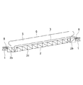
図1はこの実施の形態に係る動く歩道を示す構成図、図2は図1の動く歩道を示す断面図である。
この実施の形態に係る乗客コンベアである動く歩道は、それぞれが異なる階に離れて形成された建築梁1の間に取り付けられた剛性のトラス2と、このトラス2の上に全体が支持された主枠3と、この主枠3の長手方向に設けられ乗降口間を循環移動する循環移動体であるパレット4とを備えている。
また、主枠3は、通常、床の上に配置されて用いられるものであり、両端部のみで支持されることができる程度の剛性を有していない。
Hereinafter, embodiments of the present invention will be described with reference to the drawings. In the drawings, the same or corresponding members and parts will be described with the same reference numerals.
FIG. 1 is a block diagram showing a moving sidewalk according to this embodiment, and FIG. 2 is a cross-sectional view showing the moving sidewalk in FIG.
The moving sidewalk, which is a passenger conveyor according to this embodiment, is supported by a
Moreover, the
主枠3の上側には、一対の欄干5が長手方向に沿って設けられており、それぞれの欄干5の上側には、パレット4とともに循環移動する手摺6が取り付けられている。
トラス2と主枠3との間には、トラス2と主枠3とを固定する連結部材7が取り付けられている。
A pair of
A connecting
トラス2は、上部に水平方向内側に延びた梁2aを有しており、この梁2aの上に主枠3が支持されている。
また、トラス2は、長手方向の両端部に屈折部2bが形成され、中間部に直線部2cが形成されており、主枠3は、屈折部2bおよび直線部2cに取り付けられている。
それぞれの建築梁1と屈折部2bとの間の上面には、スロープ8が設けられており、乗客またはカート等がスムーズにパレット4へ乗り降りすることができるようになっている。
The
Further, the
A slope 8 is provided on the upper surface between each
以上説明したように、この実施の形態に係る動く歩道によれば、離れて形成された建築梁1の間に、主枠3を全体に渡って支持する剛性のトラス2が設けられているので、床の上に配置されて用いられる剛性を有さず、両端部のみで支持されることができる程度の剛性がない主枠3であっても、離れた建築梁1の間に取り付けることができる。
As described above, according to the moving sidewalk according to this embodiment, the
なお、トラス2の上下方向の厚みは、離れた建築梁1の距離に応じた剛性を有するように、調整されて形成してもよい。
これにより、動く歩道の設置スペースを効率よく利用することができる。
Note that the thickness of the
Thereby, the installation space of the moving sidewalk can be used efficiently.
実施の形態2.
図3(a)はこの実施の形態に係る動く歩道を示す構成図、図3(b)は図3(a)の動く歩道の両端部を示す拡大図である。
この実施の形態に係る動く歩道は、トラス2の直線部2cにのみ、主枠3が取り付けられている。
建築梁1から主枠3までの間のトラス2には、長手方向に延びた一対の保護柵9が取り付けられている。
その他の構成は実施の形態1と同様である。
FIG. 3A is a block diagram showing a moving sidewalk according to this embodiment, and FIG. 3B is an enlarged view showing both ends of the moving sidewalk in FIG. 3A.
In the moving sidewalk according to this embodiment, the
A pair of
Other configurations are the same as those in the first embodiment.
この実施の形態に係る動く歩道によれば、主枠3が、トラス2の直線部2cにのみ支持されているので、床の上に配置されて用いられる動く歩道の主枠3およびパレット4をそのまま、離れた建築梁1の間に配置して利用することができる。
According to the moving sidewalk according to this embodiment, since the
実施の形態3.
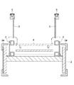
図4はこの実施の形態に係る動く歩道の構成図、図5は図4の動く歩道の断面図である。
この実施の形態に係る動く歩道は、主枠3の下側がトラス2の内側に入り込んで配置されている。したがって、主枠3はトラス2の梁2aには支持されていない。
トラス2は、主枠3を内側に入り込むために、実施の形態1のものより幅が広く形成されている。
これにより、乗降口側では、パレット4の高さと建築梁1の高さとを一致させることができるので、建築梁1と主枠3との間のトラス2にはスロープ8が取り付けられていない。
その他の構成は実施の形態1と同様である。
FIG. 4 is a block diagram of a moving sidewalk according to this embodiment, and FIG. 5 is a cross-sectional view of the moving sidewalk of FIG.
The moving sidewalk according to this embodiment is arranged such that the lower side of the
The
Thereby, since the height of the
Other configurations are the same as those in the first embodiment.
この実施の形態に係る動く歩道によれば、主枠3の下側がトラス2の内側に入り込んで配置されているので、パレット4の高さと建築梁1の高さとを一致させることができる。その結果、建築梁1と主枠3との間のトラス2にはスロープ8を取り付ける必要がなく、構成を簡単にすることができる。
According to the moving sidewalk according to this embodiment, since the lower side of the
実施の形態4.
図6はこの実施の形態に係る動く歩道の要部を示す拡大図である。
この実施の形態に係る動く歩道は、パレット4を駆動させる駆動手段10がトラス2の内側に配置されている。駆動手段10は、パレット4に動力を与える駆動部11およびこの駆動部11に電力を供給して制御する制御部12を有している。
その他の構成は実施の形態1と同様である。
FIG. 6 is an enlarged view showing a main part of the moving sidewalk according to this embodiment.
In the moving sidewalk according to this embodiment, driving means 10 for driving the
Other configurations are the same as those in the first embodiment.
この実施の形態に係る動く歩道によれば、パレット4を駆動させる駆動手段10がトラス2の内側に配置されているので、主枠3を短縮することができる。
また、駆動手段10が取り付けられたトラス2の内側は、主枠3に駆動手段10を取り付けた場合と比較して、作業スペースが広いので、駆動手段10の保守または点検を容易に行うことができる。
According to the moving sidewalk according to this embodiment, since the driving means 10 for driving the
Moreover, since the working space is wider inside the
なお、上記各実施の形態では、乗客コンベアとして、動く歩道を例に説明したが、勿論このものに限らず、エスカレータであってもよい。 In each of the above embodiments, a moving walkway is described as an example of a passenger conveyor. However, the present invention is not limited to this and may be an escalator.
なお、上記各実施の形態では、循環移動体として、パレット4を例に説明したが、勿論このものに限らず、例えば、ゴムベルトであってもよい。
In each of the above embodiments, the
1 建築梁、2 トラス、2a 梁、2b 屈折部、2c 直線部、3 主枠、4 パレット(循環移動体)、5 欄干、6 手摺、7 連結部材、8 スロープ、9 保護柵、10 駆動手段、11 駆動部、12 制御部。
DESCRIPTION OF
Claims (5)
前記主枠に支持され、乗降口間を循環移動する循環移動体とを備えた乗客コンベアにおいて、
離れて形成された建築梁の間に架設され、前記主枠を支持する剛性のトラスを備えたことを特徴とする乗客コンベア。 The main frame,
In a passenger conveyor that is supported by the main frame and includes a circulating moving body that circulates between the entrances and exits,
A passenger conveyor comprising a rigid truss that is constructed between building beams formed apart and supports the main frame.
前記主枠は、前記直線部に支持されていることを特徴とする請求項1に記載の乗客コンベア。 The truss has a refracting part at both ends and a straight part at the middle part,
The passenger conveyor according to claim 1, wherein the main frame is supported by the straight portion.
Priority Applications (1)
| Application Number | Priority Date | Filing Date | Title |
|---|---|---|---|
| JP2007263172A JP2009091111A (en) | 2007-10-09 | 2007-10-09 | Passenger conveyer |
Applications Claiming Priority (1)
| Application Number | Priority Date | Filing Date | Title |
|---|---|---|---|
| JP2007263172A JP2009091111A (en) | 2007-10-09 | 2007-10-09 | Passenger conveyer |
Publications (1)
| Publication Number | Publication Date |
|---|---|
| JP2009091111A true JP2009091111A (en) | 2009-04-30 |
Family
ID=40663475
Family Applications (1)
| Application Number | Title | Priority Date | Filing Date |
|---|---|---|---|
| JP2007263172A Pending JP2009091111A (en) | 2007-10-09 | 2007-10-09 | Passenger conveyer |
Country Status (1)
| Country | Link |
|---|---|
| JP (1) | JP2009091111A (en) |
Citations (2)
| Publication number | Priority date | Publication date | Assignee | Title |
|---|---|---|---|---|
| JPS5592675U (en) * | 1978-12-20 | 1980-06-26 | ||
| JPS58152779A (en) * | 1982-03-03 | 1983-09-10 | 株式会社日立製作所 | Method of installing man conveyor |
-
2007
- 2007-10-09 JP JP2007263172A patent/JP2009091111A/en active Pending
Patent Citations (2)
| Publication number | Priority date | Publication date | Assignee | Title |
|---|---|---|---|---|
| JPS5592675U (en) * | 1978-12-20 | 1980-06-26 | ||
| JPS58152779A (en) * | 1982-03-03 | 1983-09-10 | 株式会社日立製作所 | Method of installing man conveyor |
Similar Documents
| Publication | Publication Date | Title |
|---|---|---|
| KR101320972B1 (en) | Truss construction for a passenger conveyor | |
| KR101343938B1 (en) | Profile track integrated drive system | |
| CN105829235A (en) | Moving Walk | |
| JP6092343B1 (en) | Passenger conveyor | |
| JP2009091111A (en) | Passenger conveyer | |
| JP7086037B2 (en) | Passenger conveyor | |
| JP2013184796A (en) | Passenger conveyor | |
| US10392226B2 (en) | Machine room-less elevator | |
| JP2021001049A (en) | Passenger conveyor fence, passenger conveyor, and installation method of passenger conveyor fence | |
| JP2010202362A (en) | Passenger conveyor | |
| JP5931967B2 (en) | Passenger conveyor | |
| JP6557195B2 (en) | Passenger conveyor | |
| JP2014012563A (en) | Passenger conveyor | |
| JP5800604B2 (en) | Passenger conveyor | |
| JP2013154999A (en) | Passenger conveyor | |
| JP2010059694A (en) | Open stair apparatus | |
| JP6557196B2 (en) | Passenger conveyor | |
| JP3599620B2 (en) | Passenger conveyor | |
| JP3603690B2 (en) | Passenger conveyor | |
| JP3205330B2 (en) | Escalator device | |
| JP2008063028A (en) | Curved type passenger conveyor | |
| JP2004250187A (en) | Truss structure of passenger conveyor | |
| JP2003155185A (en) | Passenger conveying facility | |
| JP2011195267A (en) | Escalator | |
| JP2010247926A (en) | Passenger conveyor |
Legal Events
| Date | Code | Title | Description |
|---|---|---|---|
| A621 | Written request for application examination |
Effective date: 20100705 Free format text: JAPANESE INTERMEDIATE CODE: A621 |
|
| A977 | Report on retrieval |
Effective date: 20120224 Free format text: JAPANESE INTERMEDIATE CODE: A971007 |
|
| A131 | Notification of reasons for refusal |
Free format text: JAPANESE INTERMEDIATE CODE: A131 Effective date: 20121002 |
|
| A02 | Decision of refusal |
Free format text: JAPANESE INTERMEDIATE CODE: A02 Effective date: 20130219 |