JP2009082496A - Sight regeneration aid - Google Patents

Sight regeneration aid Download PDF

Info

Publication number
JP2009082496A
JP2009082496A JP2007256644A JP2007256644A JP2009082496A JP 2009082496 A JP2009082496 A JP 2009082496A JP 2007256644 A JP2007256644 A JP 2007256644A JP 2007256644 A JP2007256644 A JP 2007256644A JP 2009082496 A JP2009082496 A JP 2009082496A
Authority
JP
Japan
Prior art keywords
electrode
substrate
visual reproduction
assisting device
reproduction assisting
Prior art date
Legal status (The legal status is an assumption and is not a legal conclusion. Google has not performed a legal analysis and makes no representation as to the accuracy of the status listed.)
Pending
Application number
JP2007256644A
Other languages
Japanese (ja)
Inventor
Yasuo Terasawa
靖雄 寺澤
Koji Osawa
孝治 大澤
Current Assignee (The listed assignees may be inaccurate. Google has not performed a legal analysis and makes no representation or warranty as to the accuracy of the list.)
Nidek Co Ltd
Original Assignee
Nidek Co Ltd
Priority date (The priority date is an assumption and is not a legal conclusion. Google has not performed a legal analysis and makes no representation as to the accuracy of the date listed.)
Filing date
Publication date
Application filed by Nidek Co Ltd filed Critical Nidek Co Ltd
Priority to JP2007256644A priority Critical patent/JP2009082496A/en
Publication of JP2009082496A publication Critical patent/JP2009082496A/en
Pending legal-status Critical Current

Links

Images

Abstract

<P>PROBLEM TO BE SOLVED: To provide a sight regeneration aid which improves the durability of long-time implantation and appropriately gives electric stimulations. <P>SOLUTION: The sight regeneration aid is provided with electrodes formed on the respective tips of a plurality of lead wires formed on a prescribed board, and a control means to make the electrodes output electric stimulation pulse signals via the lead wires in order to electrically stimulate the cells or tissue composing the sight nerve system of a patient's sight. These electrodes consist of a first electrode with the shape of convex upward connected with the end of each lead wire on the board, and a second electrode larger than the first electrode in diameter and fitted to the end of the first electrode. <P>COPYRIGHT: (C)2009,JPO&INPIT

Description

本発明は患者の視覚を再生するための視覚再生補助装置に関する。   The present invention relates to a visual reproduction assisting device for reproducing the vision of a patient.

近年、失明治療技術の一つとして、複数の電極が形成された基板を有する体内装置を体内に埋植し、網膜を構成する細胞を電気刺激して視覚の再生を試みる視覚再生補助装置の研究がされている。このような視覚再生補助装置は、例えば、体外装置を用いて撮像された映像を所定の信号に変換して体内に設置された体内装置に送信し、電極から刺激パルス信号を出力して網膜を構成する細胞を電気刺激することにより、視覚の再生を試みる装置が知られている(例えば、特許文献1参照)。
特開2003−230590号公報
In recent years, as one of the techniques for treating blindness, research on visual regeneration assisting devices that attempt to regenerate vision by implanting in-vivo devices with a substrate on which multiple electrodes are formed and electrically stimulating cells that make up the retina Has been. Such a visual reproduction assist device, for example, converts an image captured using an extracorporeal device into a predetermined signal and transmits it to an in-vivo device installed in the body, outputs a stimulation pulse signal from the electrode, and An apparatus that attempts to reproduce vision by electrically stimulating constituent cells is known (see, for example, Patent Document 1).
JP 2003-230590 A

このような装置では、体内への長期埋植に耐える耐久性と、好適に網膜を構成する細胞を電気刺激できる性能を備える電極が必要とされる。特許文献1の装置では、通常、電極が薄膜形成法により作製されるため、電極に厚みを持たせることが難しく、電極の表面積を広げることが困難である。この結果、出力可能な電流量が制限され好適に電気刺激を行い難いという問題があった。   Such a device requires an electrode that has durability to withstand long-term implantation in the body and that can suitably stimulate the cells that make up the retina. In the apparatus of Patent Document 1, since the electrode is usually manufactured by a thin film forming method, it is difficult to give the electrode a thickness and it is difficult to increase the surface area of the electrode. As a result, there is a problem that the amount of current that can be output is limited and it is difficult to perform electrical stimulation suitably.

上記従来技術の問題点に鑑み、長期埋植の耐久性が向上されると共に、電気刺激を好適に行うことのできる視覚再生補助装置を提供することを技術課題とする。   In view of the above-described problems of the prior art, it is an object of the present invention to provide a visual reproduction assisting device that can improve the durability of long-term implantation and can suitably perform electrical stimulation.

上記技術課題を解決するために、本発明は以下のような構成を備えることを特徴とする。
(1) 所定の基板に形成された複数の導線の先端に各々形成される電極と、患者の視覚を形成する視覚神経系を構成する細胞又は組織を電気刺激するために前記導線を介して前記電極から電気刺激パルス信号を出力させる制御手段と、を備える視覚再生補助装置において、前記電極は、前記導線の先端に接続され前記基板上に凸状に形成される第1電極と、該第1電極の径よりも大きな第2電極であって,前記第1電極の先端部に接合される第2電極とからなることを特徴とする。
(2) (1)の視覚再生補助装置において、前記第2電極は、前記第1電極の少なくとも先端と嵌合するための凹部又は貫通孔が形成されており、前記第1電極に第2電極をを嵌合させた状態でかしめることにより一の電極として一体化されていることを特徴とする。
(3) (1)の視覚再生補助装置において、前記第2電極は、前記第1電極の先端部にかしめられることにより、前記第1電極と前記第2電極とで前記基板を挟持することを特徴とする。
(4) (1)の視覚再生補助装置において、前記第1電極は前記フレキシブル基板を貫通する柱状部材と、該柱状部材の基部に形成される基台であって,前記基板から前記第1電極が脱落することを防ぐ程度の大きさに形成された基台と、からなることを特徴とする。
(5) (1)の視覚再生補助装置において、前記導線は、生体適合性を有すると共に絶縁性を有する素材にて被覆されていることを特徴とする。
(6) (1)の視覚再生補助装置において、前記基板は、前記第1電極の先端部が貫通される貫通孔を有する第1基板と、前記第1電極を前記第1基板とで挟持する第2基板とで構成されることを特徴とする。
(7) (6)の視覚再生補助装置において、前記導線は、生体適合性を有すると共に絶縁性を有する素材にて被覆されており、該導線は、前記第1電極の先端に接続されると共に、第1基板と第2基板とで挟持されることを特徴とする。
In order to solve the above technical problem, the present invention is characterized by having the following configuration.
(1) The electrodes formed on the tips of a plurality of conductors formed on a predetermined substrate, and the cells or tissues constituting the visual nervous system that forms the vision of the patient via the conductors for electrical stimulation. And a control means for outputting an electrical stimulation pulse signal from the electrode, wherein the electrode is connected to a leading end of the conducting wire and formed in a convex shape on the substrate, and the first electrode The second electrode is larger than the diameter of the electrode, and the second electrode is joined to the tip of the first electrode.
(2) In the visual reproduction assisting device according to (1), the second electrode is formed with a recess or a through hole for fitting with at least a tip of the first electrode, and the second electrode is formed on the first electrode. It is characterized by being integrated as one electrode by caulking in a state of fitting.
(3) In the visual reproduction assisting device according to (1), the second electrode is clamped to a tip portion of the first electrode, whereby the substrate is sandwiched between the first electrode and the second electrode. Features.
(4) In the visual reproduction assisting device according to (1), the first electrode is a columnar member penetrating the flexible substrate and a base formed at a base portion of the columnar member, and the first electrode extends from the substrate. It is characterized by comprising a base formed in a size that prevents the falling off of the base.
(5) In the visual reproduction assisting device according to (1), the conductive wire is covered with a material having biocompatibility and insulating properties.
(6) In the visual reproduction assisting device according to (1), the substrate sandwiches the first electrode between the first substrate having a through-hole through which the tip of the first electrode passes, and the first substrate. It is characterized by comprising a second substrate.
(7) In the visual reproduction assisting device according to (6), the conducting wire is covered with a material having biocompatibility and insulating properties, and the conducting wire is connected to a tip of the first electrode. And being sandwiched between the first substrate and the second substrate.

本発明によれば、長期埋植の耐久性が向上されると共に、電気刺激を好適に行うことができる。   According to the present invention, durability of long-term implantation can be improved and electrical stimulation can be suitably performed.

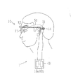
本発明の実施の形態を図面を用いて説明する。図1は視覚再生補助装置の外観を示した概略図、図2は視覚再生補助装置における体内装置を示す図である。   Embodiments of the present invention will be described with reference to the drawings. FIG. 1 is a schematic diagram showing an external appearance of a visual reproduction assistance device, and FIG. 2 is a diagram showing an in-vivo device in the visual reproduction assistance device.

視覚再生補助装置1は、図1及び図2に示すように、外界を撮影するための体外装置10と、網膜を構成する細胞に電気刺激を与え視覚の再生を促す体内装置20とからなる。体外装置10は、患者が掛けるバイザ11と、バイザ11に取り付けられるCCDカメラ等からなる撮影装置12と、外部デバイス13、一次コイルからなる送信手段14等にて構成されている。   As shown in FIGS. 1 and 2, the visual reproduction assisting device 1 includes an extracorporeal device 10 for photographing the outside world, and an in-vivo device 20 that promotes visual reproduction by applying electrical stimulation to cells constituting the retina. The extracorporeal device 10 includes a visor 11 on which a patient is placed, an imaging device 12 including a CCD camera attached to the visor 11, an external device 13, a transmission unit 14 including a primary coil, and the like.

外部デバイス13には、CPU等の演算処理回路を有するデータ変調手段13a、視覚再生補助装置1(体外装置10及び体内装置20)の電力供給を行うためのバッテリ13bが設けられている。データ変調手段13aは、撮影装置12にて撮影した被写体像を画像処理し、さらに得られた画像処理後のデータを、視覚を再生するための電気刺激パルス用データに変換する処理を行う。送信手段14は、データ変調手段13aにて変換された電気刺激パルス用データ及び後述する体内装置20を駆動させるための電力を所定の信号、本実施形態では、電磁波として体内装置20側に伝送(無線送信)する。この電磁波には、電気刺激パルス用データと電力が重畳されている。また、送信手段14の中心には図示なき磁石が取り付けられている。磁石は後述する受信手段31との位置固定に使用される。   The external device 13 is provided with a data modulation means 13a having an arithmetic processing circuit such as a CPU, and a battery 13b for supplying power to the visual reproduction auxiliary device 1 (external device 10 and internal device 20). The data modulation unit 13a performs image processing on the subject image captured by the image capturing device 12, and further converts the obtained image processed data into electrical stimulation pulse data for reproducing vision. The transmission means 14 transmits the electrical stimulation pulse data converted by the data modulation means 13a and the power for driving the in-vivo device 20 described later to the in-vivo device 20 side as a predetermined signal, in this embodiment, an electromagnetic wave ( Wireless transmission). On this electromagnetic wave, electrical stimulation pulse data and power are superimposed. A magnet (not shown) is attached to the center of the transmission means 14. The magnet is used to fix the position with the receiving means 31 described later.

バイザ11は眼鏡形状を有しており、図1に示すように、患者の眼前に装着して使用することができるようになっている。また、撮影装置12はバイザ11の前面に取り付けてあり、患者に視認させる被写体を撮影することができる。   The visor 11 has an eyeglass shape, and can be used by being mounted in front of the patient's eyes as shown in FIG. The photographing device 12 is attached to the front surface of the visor 11 and can photograph a subject to be visually recognized by the patient.

次に、体内装置20の構成を説明する。図2(a)は、体内装置20の外観を示し、図2(b)は刺激部40の断面を示した図である。体内装置20は、大別して体外装置10から送信される電気刺激パルス信号用データや電力を電磁波にて受け取る受信部(受信ユニット)30と、網膜を構成する細胞を電気刺激する刺激部(刺激ユニット)40により構成される。受信部30には、体外装置10からの電磁波を受信する2次コイルからなる受信手段31や、制御部32が設けられている。制御部32は、受信手段31にて受信された電気刺激パルス用データと電力とを分けるとともに、電気刺激パルス用データを基に、視覚を得るための電気刺激パルス信号と、電気刺激パルス信号と対応する(電気刺激パルス信号を出力させる)電極を指定する電極指定信号等を含む制御信号とに変換し、刺激部40へ送信するための役割を有している。   Next, the configuration of the intracorporeal device 20 will be described. 2A shows an external appearance of the in-vivo device 20, and FIG. 2B shows a cross section of the stimulation unit 40. As shown in FIG. The in-vivo device 20 is roughly divided into a receiving unit (receiving unit) 30 that receives data and electric power for electrical stimulation pulse signals transmitted from the extracorporeal device 10 by electromagnetic waves, and a stimulating unit (stimulating unit) that electrically stimulates cells constituting the retina. ) 40. The receiving unit 30 is provided with a receiving unit 31 including a secondary coil that receives electromagnetic waves from the extracorporeal device 10 and a control unit 32. The control unit 32 separates the electrical stimulation pulse data and the power received by the receiving unit 31, and based on the electrical stimulation pulse data, an electrical stimulation pulse signal for obtaining vision, an electrical stimulation pulse signal, It has a role for converting to a control signal including an electrode designation signal for designating a corresponding electrode (for outputting an electrical stimulation pulse signal) and transmitting the control signal to the stimulation unit 40.

これら受信手段31や制御部32は、基板33上に形成されている。なお、受信部30には送信手段14を位置固定させるための図示なき磁石が設けられている。対向電極(帰還電極)34はそれぞれの電極44の対向して配置され、効率的に細胞等を電気刺激するための部材である。   These receiving means 31 and control unit 32 are formed on a substrate 33. The receiving unit 30 is provided with a magnet (not shown) for fixing the position of the transmitting unit 14. The counter electrode (return electrode) 34 is a member for opposing each electrode 44 to efficiently electrically stimulate cells and the like.

また、刺激部40は、電気刺激パルス信号を出力する複数の電極44、刺激制御部42(制御手段)、これらを設置する基板43を含む。各電極44は、後述する作製方法(接続形態)にて各々が刺激制御部42に接続される(詳細は後述する)。刺激制御部42は、制御部32から送られてきた制御信号(電極指定信号を含む)に基づいて、対応する電気刺激パルス信号を電極44の各々へ振り分けるマルチプレクサ機能を有する。電極44には生体適合性が高い金属、例えば金や白金、窒化チタン、酸化イリジウム等が用いられる。各電極44は、外径が100〜500μm、高さが100〜500μmに形成される。本実施形態で用いられる基板43は、眼内、特に、層状の眼組織内に設置されるため、眼球の形状に沿うことが好ましく、層間(層内)に長期埋植されても患者の負担が少ないことが好ましい。このため、基板43は、パリレン、ポリプロピレン、ポリイミド等、生体適合性が高く、所定の厚さにおいて折り曲げ可能(フレキシブル)な材料を長手方向に延びた平板状に加工したものを用いる。基板43の厚みは、10〜100μmとされる。この基板43には、電極44と刺激制御部42が電気的に接続する導線であるワイヤ41が配置される。ワイヤ41は、生体適合性の高い金属、例えば、金、白金等から形成され、その表面を生体適合性を有すると共に絶縁性を有する素材、例えば、パリレン、ポリイミド等の樹脂にて被覆される。ワイヤ41の厚み(径)は、基板43のフレキシブル性や長期設置性に好ましい程度の厚み、例えば、10〜100μmとされる。基板43上に実装された刺激制御部42はワイヤ41を介して基板43上に複数個形成された電極44と接続される。後述する電極44の作製方法により、ワイヤ41が基板43にて覆われることにより、ワイヤ41の金属部分は絶縁性を有する被覆に二重に覆われるため、ワイヤ41部分に体液等の浸潤がしても、漏電等の可能性が低くなる。   The stimulation unit 40 includes a plurality of electrodes 44 that output electrical stimulation pulse signals, a stimulation control unit 42 (control means), and a substrate 43 on which these are installed. Each electrode 44 is connected to the stimulation control unit 42 by a manufacturing method (connection form) described later (details will be described later). The stimulation control unit 42 has a multiplexer function that distributes the corresponding electrical stimulation pulse signal to each of the electrodes 44 based on the control signal (including the electrode designation signal) sent from the control unit 32. For the electrode 44, a metal having high biocompatibility, for example, gold, platinum, titanium nitride, iridium oxide, or the like is used. Each electrode 44 has an outer diameter of 100 to 500 μm and a height of 100 to 500 μm. Since the substrate 43 used in the present embodiment is installed in the eye, particularly in a layered eye tissue, it preferably conforms to the shape of the eyeball, and even if it is implanted in the interlayer (in the layer) for a long period of time, it is a burden on the patient. It is preferable that there is little. For this reason, the board | substrate 43 uses what was processed into the flat plate shape extended in the longitudinal direction, such as parylene, a polypropylene, a polyimide, etc., which has high biocompatibility, and was bendable (flexible) in predetermined thickness. The thickness of the substrate 43 is 10 to 100 μm. On this substrate 43, a wire 41, which is a conductive wire that electrically connects the electrode 44 and the stimulation control unit 42, is disposed. The wire 41 is formed from a metal having high biocompatibility, such as gold or platinum, and the surface thereof is covered with a material having biocompatibility and insulation properties, such as a resin such as parylene or polyimide. The thickness (diameter) of the wire 41 is set to a thickness preferable for the flexibility and long-term installation of the substrate 43, for example, 10 to 100 μm. The stimulation control unit 42 mounted on the substrate 43 is connected to a plurality of electrodes 44 formed on the substrate 43 through wires 41. Since the wire 41 is covered with the substrate 43 by a method for manufacturing the electrode 44 described later, the metal portion of the wire 41 is doubly covered with an insulating coating, so that infiltration of body fluid or the like is infiltrated into the wire 41 portion. However, the possibility of leakage etc. is reduced.

刺激制御部42は、各半導体素子の組合せにより機能を果たす半導体の集積回路であり、半導体基板上に集積回路を機能させるパターン配線が形成された面を基板43側にして接合されている。また、詳細な説明は略すが、刺激制御部42は、その周囲をメッキなどに覆われており、生体からの浸潤等を低減させる構成とされる。なお、刺激制御部42は、セラミックスや金属にて形成された気密ケースを用いて密封処理される構成としてもよい。このような場合、刺激制御部42は、ケースに設けられたビアを介してワイヤ41と接続される。   The stimulus control unit 42 is a semiconductor integrated circuit that performs a function by a combination of semiconductor elements, and is bonded to the surface of the semiconductor substrate on which the pattern wiring for functioning the integrated circuit is formed. Although detailed description is omitted, the stimulus control unit 42 is covered with plating or the like to reduce infiltration from a living body. The stimulus control unit 42 may be configured to be sealed using an airtight case formed of ceramics or metal. In such a case, the stimulus control unit 42 is connected to the wire 41 via a via provided in the case.

また、体内において離れた位置に置かれる受信部30と刺激部40とは複数のワイヤ(導線)50によって電気的に接続されている。ワイヤ50は、体内に設置された際に眼球運動に対応した伸縮性、耐久性を備えることが好ましく、上述のワイヤ41と同様の素材にて作製される。受信部30に一端を接続されたワイヤ50は、刺激部40に配置されたワイヤ41の末端部分に接続される。詳細な説明は略すが、ワイヤ50とワイヤ41は、熔接や圧着等により接続される。また、ワイヤ50は、取扱いし易いように、生体適合性の高い素材、例えば、シリコーン、パリレン等により作製されたケーブル51に収められる。   In addition, the receiving unit 30 and the stimulating unit 40 placed at positions separated from each other in the body are electrically connected by a plurality of wires (conductive wires) 50. The wire 50 preferably has elasticity and durability corresponding to eye movement when placed in the body, and is made of the same material as the wire 41 described above. The wire 50 having one end connected to the receiving unit 30 is connected to the end portion of the wire 41 arranged in the stimulating unit 40. Although detailed description is omitted, the wire 50 and the wire 41 are connected by welding, pressure bonding, or the like. Further, the wire 50 is housed in a cable 51 made of a material having high biocompatibility, for example, silicone, parylene, etc. so as to be easily handled.

なお、図示は略すが、受信部30は、ケーブル51、対向電極34を外に出して、気密性の高い容器に収められ、その容器の蓋を密閉される。さらに、容器の上から生体適合性がよく絶縁性を有する樹脂等でコーティングされる。これにより、受信部30はハーメチックシールされる。   In addition, although illustration is abbreviate | omitted, the receiving part 30 takes out the cable 51 and the counter electrode 34, is accommodated in a highly airtight container, and the lid | cover of the container is sealed. Furthermore, it is coated from above the container with a resin having good biocompatibility and insulating properties. Thereby, the receiver 30 is hermetically sealed.

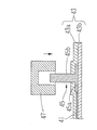
次に、電極44について説明する。図3は、電極44付近の模式的断面図であり、電極44は2つの電極部材が接合することにより形成されている。図4は、電極44の作製方法(電極44とワイヤ41とを接続する方法)を段階的に示した図である。図は説明の簡便のため、各部材の縮尺は模式的としている。   Next, the electrode 44 will be described. FIG. 3 is a schematic sectional view of the vicinity of the electrode 44. The electrode 44 is formed by joining two electrode members. FIG. 4 is a diagram showing stepwise a method for manufacturing the electrode 44 (a method for connecting the electrode 44 and the wire 41). In the figure, the scale of each member is schematic for ease of explanation.

基板43は、第1基板となるベース部43aと、第2基板となるカバー部43bにて構成されており、ベース部43aとカバー部43bの間には、第1の電極となる台座45と、台座45に接続されたワイヤ41が挟持されている。台座45は、平板状に形成されるベース部43aとカバー部43bに挟まれる基台45aと、基台45aを基部として柱状(凸状)に延びた柱部材45bにより構成される。台座45は、生体適合性を有し、塑性又は展性を有する導体、例えば、白金や金等の金属にて成形される。柱部材45bの長さ(柱の高さ)は、ベース部43aの厚みよりも長く、後述するワッシャ(座金、ハトメ)46よりも長く突き出る長さを持つ。柱部材45bの先端部は、ベース部43aを貫通し、基板43(ベース部43a)から突出しており、後述するワッシャ46をかしめる際の軸となる。また、柱部材45bは先端に向かって先細りになるテーパ状に形成されることが好ましい。これにより、後述するワッシャ46を柱部材45bに嵌合し易くなる。基台45aの外径D2は、柱部材45bが持つ外径D1よりも大きくされ、台座45がベース部43a(基板43)から脱落することを防ぐ役割を持つ。なお、ワイヤ41は、基台45aに接続される。   The substrate 43 includes a base portion 43a serving as a first substrate and a cover portion 43b serving as a second substrate. Between the base portion 43a and the cover portion 43b, a base 45 serving as a first electrode and The wire 41 connected to the pedestal 45 is sandwiched. The pedestal 45 includes a base part 43a formed in a flat plate shape and a base part 45a sandwiched between the cover part 43b, and a column member 45b extending in a columnar shape (convex shape) with the base part 45a as a base part. The pedestal 45 is biocompatible and is formed of a plastic or malleable conductor, for example, a metal such as platinum or gold. The length of the column member 45b (the height of the column) is longer than the thickness of the base portion 43a and protrudes longer than a washer (washer, eyelet) 46 described later. The distal end portion of the column member 45b penetrates the base portion 43a and protrudes from the substrate 43 (base portion 43a), and serves as an axis for caulking a washer 46 described later. The column member 45b is preferably formed in a tapered shape that tapers toward the tip. Thereby, it becomes easy to fit the washer 46 mentioned later to the pillar member 45b. The outer diameter D2 of the base 45a is made larger than the outer diameter D1 of the column member 45b, and has a role of preventing the base 45 from falling off the base portion 43a (substrate 43). The wire 41 is connected to the base 45a.

ワッシャ46は、第2の電極となり、中央に柱部材45bを通すための貫通孔46aを有する柱状の環状部材である。さらにワッシャ46の貫通孔出口はすり鉢状の形状を有し、柱部材45bを押しつぶしたときに柱部材45bの先端がそのすり鉢形状に沿って押し広げられるようにしている。ワッシャ46は、台座45と同様に、生体適合性を有し、塑性又は展性を有する導体、例えば、白金や金等の金属にて成形される。ワッシャ46は台座45と同じ材料であることが好ましい。図示されるように、ワッシャ46は、台座45とで、ベース部43aを挟持している。台座45及びワッシャ46は変形されて、一体的に接続されることで、電極44が形成される。電極44の外径は100〜500μm、基板43から突出した部分の高さは100〜300μmとされることが好ましい。なお、台座45、ワッシャ46は、プレス加工や切り出し加工にて成形される。   The washer 46 is a columnar annular member that serves as a second electrode and has a through hole 46a through which the column member 45b passes. Further, the outlet of the through hole of the washer 46 has a mortar shape, and when the column member 45b is crushed, the tip of the column member 45b is pushed and expanded along the mortar shape. As with the base 45, the washer 46 is biocompatible and is formed of a plastic or malleable conductor, for example, a metal such as platinum or gold. The washer 46 is preferably made of the same material as the pedestal 45. As shown in the drawing, the washer 46 sandwiches the base portion 43 a with the pedestal 45. The pedestal 45 and the washer 46 are deformed and integrally connected to form the electrode 44. The outer diameter of the electrode 44 is preferably 100 to 500 μm, and the height of the portion protruding from the substrate 43 is preferably 100 to 300 μm. The pedestal 45 and the washer 46 are formed by pressing or cutting.

次に、電極44の作製方法を、図4に基づき説明する。図4(a)に示すステップでは、
台座45の基台45aにワイヤ41が接続される。この接続には、レーザ熔接や抵抗熔接等の熔接技術が用いられる。このとき、ワイヤ41の熔接箇所は、熔接時の熱により、樹脂による被覆が取り除かれるため、台座45とワイヤ41は機械的に接続されると共に、電気的に接続される。なお、柱部材45bの長さは、400〜700μm程度とされ、外径D1は、30〜300μm程度とされる。なお、台座45とワイヤ41の接続は、圧着加工(塑性変形加工)等を用いた機械的接続であってもよい。このように台座45とワイヤ41とを接続した状態で、次に平板状に作製した樹脂性のベース部43aの貫通孔43cに台座45の柱部材45bを通す(図4(b)参照)。なお、貫通孔43cは、レーザ加工や機械加工により柱部材45bを貫通させる程度の大きさに形成されている。なお、貫通孔43cはベース部43aにおいて、電極44(台座45)の数だけ所定の位置に形成されている。また、本実施形態ではワイヤ41と台座45とを接続するものとしているが、これに限るものではなく、ベース部43aに予め導線を形成しておき、その先端に貫通孔を開けて台座を取り付けるようにすることもできる。
Next, a method for manufacturing the electrode 44 will be described with reference to FIG. In the step shown in FIG.
The wire 41 is connected to the base 45 a of the base 45. For this connection, welding techniques such as laser welding and resistance welding are used. At this time, the welded portion of the wire 41 is mechanically connected and electrically connected to the pedestal 45 and the wire 41 because the resin coating is removed by heat during welding. The length of the column member 45b is about 400 to 700 μm, and the outer diameter D1 is about 30 to 300 μm. The connection between the pedestal 45 and the wire 41 may be a mechanical connection using a crimping process (plastic deformation process) or the like. With the pedestal 45 and the wire 41 thus connected, the column member 45b of the pedestal 45 is then passed through the through hole 43c of the resinous base portion 43a produced in a flat plate shape (see FIG. 4B). The through hole 43c is formed to a size that allows the column member 45b to pass through by laser processing or machining. The through holes 43c are formed at predetermined positions in the base portion 43a by the number of the electrodes 44 (base 45). In this embodiment, the wire 41 and the pedestal 45 are connected to each other. However, the present invention is not limited to this. A conductive wire is formed in advance in the base portion 43a, and a pedestal is attached by opening a through hole at the tip. It can also be done.

次に、ベース部43aに台座45を取り付けた状態で、基台45a側に、蒸着法等を用いて、ベース部43aと同種の樹脂にて、フレキシブル性を有する平板状のカバー部43bを形成する(図4(c)参照)。このとき、柱部材45bの先端部に樹脂による層が形成されないように、先端部にマスクをするか又はベース部43aの基台45a側にのみ樹脂による層が形成されるようにする。このようにして、基台45a及びワイヤ41は、ベース部43aとカバー部43bにて挟持(包埋)され、柱部材45bが、基板43上に凸状に形成されることとなる。また、基台45aの外径D2は貫通孔43cの径よりも大きく形成されるため、台座45は基板43より脱落することがない。このようにして、基板43上にワイヤ41が接続された台座45が凸状に配置されたものが作製される。   Next, with the base 45 attached to the base portion 43a, a flat plate-like cover portion 43b having flexibility is formed on the base 45a side using the same kind of resin as the base portion 43a by using a vapor deposition method or the like. (See FIG. 4C). At this time, in order not to form a resin layer at the tip of the column member 45b, the tip is masked or a resin layer is formed only on the base 45a side of the base portion 43a. In this way, the base 45a and the wire 41 are sandwiched (embedded) by the base portion 43a and the cover portion 43b, and the column member 45b is formed in a convex shape on the substrate 43. Further, since the outer diameter D2 of the base 45a is formed larger than the diameter of the through hole 43c, the pedestal 45 does not fall off the substrate 43. In this way, a substrate 45 in which the pedestal 45 to which the wire 41 is connected is disposed on the substrate 43 is manufactured.

次に、柱部材45b(台座45)の先端部に、ワッシャ46が嵌合される(図4(d)参照)。ワッシャ46の外径D3は、柱部材45bの外径D1よりも十分に大きく形成されている。また、貫通孔46aの径D4(ワッシャ46の内径)は、柱部材45bをできるだけ隙間無く通すことができる径(外形D1よりも若干大きい径)とされることが好ましい。ワッシャ46の外径D3は300〜700μmとされ、ワッシャ46の高さ(孔方向の長さ)は、300〜500μmとされる。   Next, the washer 46 is fitted to the tip of the column member 45b (base 45) (see FIG. 4D). The outer diameter D3 of the washer 46 is formed sufficiently larger than the outer diameter D1 of the column member 45b. The diameter D4 of the through hole 46a (the inner diameter of the washer 46) is preferably a diameter that allows the column member 45b to pass therethrough as little as possible (a diameter slightly larger than the outer diameter D1). The outer diameter D3 of the washer 46 is 300 to 700 μm, and the height (length in the hole direction) of the washer 46 is 300 to 500 μm.

柱部材45bにワッシャ46を嵌合すると、ワッシャ46の一端(底面)がベース部43aに当接された状態で、柱部材45bの先端はワッシャ46の上面より突き出る。この状態で、ワッシャ46の他端(図では上部)と柱部材45bの先端とをプレス加工することにより、柱部材45bが押しつぶされた状態で柱部材45bを軸(支え)としてワッシャ46がかしめられ(塑性変形され)、台座45とワッシャ46が一体化され、図3に示すような電極44が基板43上に作製される。また、このステップを繰り返すことにより、図2に示されるように複数の電極44が基板43上に形成される。このとき、ワッシャ46は、ベース部43aに押圧されて固定されるため、ベース部43aとワッシャ46の間に体液等が浸潤しにくくなる。このため、貫通孔43cがある程度大きく形成されていても、基板43内に体液等が浸潤しにくくなる。また、このとき、柱部材45bは、基台45a方向に縮められると共に、側方向(ワッシャ46方向)に伸展され、柱部材45bとワッシャ46は密着される。このため、柱部材45bとワッシャ46との間に多少の隙間があってもよい。これにより、電極44の外径は100〜500μm、基板43から突出した部分の高さは100〜300μmとされる。このような電極44は、同程度の直径を持つ薄膜電極よりも表面積が大きく充分な電流を流すことができる。なお、薄膜形成法により薄膜層の形成を繰り返して、電極44のようなサイズの電極を作製することは容易でない。   When the washer 46 is fitted to the column member 45 b, the tip of the column member 45 b protrudes from the upper surface of the washer 46 in a state where one end (bottom surface) of the washer 46 is in contact with the base portion 43 a. In this state, the other end (the upper portion in the figure) of the washer 46 and the tip end of the column member 45b are pressed, and the washer 46 is caulked with the column member 45b as an axis (support) in a state where the column member 45b is crushed. Then, the base 45 and the washer 46 are integrated, and an electrode 44 as shown in FIG. Further, by repeating this step, a plurality of electrodes 44 are formed on the substrate 43 as shown in FIG. At this time, since the washer 46 is pressed and fixed to the base portion 43a, body fluid or the like hardly infiltrates between the base portion 43a and the washer 46. For this reason, even if the through-hole 43c is formed to be large to some extent, the body fluid or the like hardly infiltrates into the substrate 43. At this time, the column member 45b is contracted in the direction of the base 45a and extended in the side direction (in the direction of the washer 46), and the column member 45b and the washer 46 are brought into close contact with each other. For this reason, there may be a slight gap between the column member 45 b and the washer 46. Thereby, the outer diameter of the electrode 44 is set to 100 to 500 μm, and the height of the portion protruding from the substrate 43 is set to 100 to 300 μm. Such an electrode 44 has a larger surface area than the thin film electrode having the same diameter and can pass a sufficient current. In addition, it is not easy to produce an electrode having a size like the electrode 44 by repeatedly forming a thin film layer by a thin film forming method.

以上のようにして、基台45とワッシャ46から基板43上に表面積の大きい(体積の大きい)一つの電極(バルク電極)44が作製される。これにより、刺激部40を体内に長期埋植し、電極44から電気刺激パルス信号が出力され続け、電極44の一部が電気化学反応等により溶解したとしても、電極44の表面積(体積)はほとんど変化しない。従って、長期埋植に際しても、電極44からは充分な電流量の電気刺激パルス信号を出力する(充分な量の電荷を注入する)ことができ、細胞等を好適に電気刺激することができる。さらに、このような構成にすることにより、第1電極である台座45のサイズ、形状等を変えずに、第2電極であるワッシャ46のサイズ、形状を任意にできるため、電極44を任意のサイズ、形状とできる。   As described above, one electrode (bulk electrode) 44 having a large surface area (large volume) is produced on the substrate 43 from the base 45 and the washer 46. As a result, even if the stimulation unit 40 is implanted in the body for a long period of time and an electrical stimulation pulse signal is continuously output from the electrode 44 and a part of the electrode 44 is dissolved by an electrochemical reaction or the like, the surface area (volume) of the electrode 44 is Almost no change. Accordingly, even during long-term implantation, an electrical stimulation pulse signal with a sufficient amount of current can be output from the electrode 44 (a sufficient amount of charge can be injected), and cells and the like can be electrically stimulated. Further, by adopting such a configuration, the size and shape of the washer 46 as the second electrode can be arbitrarily set without changing the size and shape of the pedestal 45 as the first electrode. Size and shape.

また、同程度の径を持つ薄膜電極と比較した場合、電極44は基板43上で立体的に突出して作製されるため、表面積が広いと共に、細胞等への接触面積が広くなる。ここで、電極が注入可能な電荷量は、電極の表面積に比例することから、電極44の表面積を広くすることにより、電極44から注入可能な電荷量を大きくできる。これにより、細胞等を好適に電気刺激できる。   Further, when compared with a thin film electrode having the same diameter, the electrode 44 is produced by projecting three-dimensionally on the substrate 43, so that it has a large surface area and a large contact area with cells and the like. Here, since the amount of charge that can be injected by the electrode is proportional to the surface area of the electrode, the amount of charge that can be injected from the electrode 44 can be increased by increasing the surface area of the electrode 44. Thereby, a cell etc. can be electrically stimulated suitably.

また、電極44と薄膜電極とで同じ電荷量の電気刺激パルス信号を出力させる場合、表面積の大きい電極44の方が電荷密度を小さくできる。このため、表面積の大きい電極は、薄膜電極の場合と同じ電荷量の電気刺激であっても、特定の細胞等に電荷が集中しにくい。従って、電極の表面積を大きくすることにより、電気刺激による細胞等への負担が軽減できる。   Further, when the electrical stimulation pulse signal having the same charge amount is output by the electrode 44 and the thin film electrode, the electrode 44 having a larger surface area can reduce the charge density. For this reason, an electrode with a large surface area is less likely to concentrate charges on specific cells or the like, even with the same amount of electrical stimulation as in the case of a thin film electrode. Therefore, by increasing the surface area of the electrode, the burden on cells and the like due to electrical stimulation can be reduced.

また、患者が知覚する視覚の解像度(分解能)が向上されることが好ましい。従って、一つの電極により電気刺激される細胞、組織の範囲を小さくしつつ、電極を高密度に配置する必要がある。このため、電極の直径をできるだけ小さくしつつ、電極の表面積を大きくする必要がある。これを受けて、前述した電極44の作製方法で用いる基台45及びワッシャ46の外径を小さくすると共に、柱部材45b及びワッシャ46の高さを長くする。これにより、直径が小さく、基板43上への突出長を長い電極44が作製できる。これにより、一つの電極が刺激する範囲を小さくできると共に、基板上43に配置される電極44の密度を向上でき、患者が知覚する視覚の解像度を向上できる。   Moreover, it is preferable that the visual resolution (resolution) perceived by the patient is improved. Therefore, it is necessary to arrange the electrodes at high density while reducing the range of cells and tissues that are electrically stimulated by one electrode. For this reason, it is necessary to increase the surface area of the electrode while reducing the diameter of the electrode as much as possible. In response to this, the outer diameters of the base 45 and the washer 46 used in the method for manufacturing the electrode 44 described above are reduced, and the heights of the column member 45b and the washer 46 are increased. As a result, an electrode 44 having a small diameter and a long protrusion length onto the substrate 43 can be produced. Thereby, while the range which one electrode stimulates can be made small, the density of the electrode 44 arrange | positioned on the board | substrate 43 can be improved, and the visual resolution which a patient perceives can be improved.

また、電極44は、大きな表面積を有するため、薄膜電極を用いた電荷の注入と比較すると、同等の電荷量を同一の電荷密度でより短時間に注入できる。このため、電気刺激パルス信号の時間幅を短くでき、刺激頻度を高くできる。これにより、患者が知覚する視覚の時間分解能(フレームレート)を高くできる。   In addition, since the electrode 44 has a large surface area, it is possible to inject an equivalent amount of charge with the same charge density in a shorter time compared to the injection of charge using a thin film electrode. For this reason, the time width of the electrical stimulation pulse signal can be shortened, and the stimulation frequency can be increased. Thereby, the visual temporal resolution (frame rate) perceived by the patient can be increased.

なお、以上の説明では、第2電極であるワッシャ46に貫通孔46aが設けられる構成としたがこれに限るものではない。第1電極である台座45(柱部材45b)の先端が、第2電極となる部材に嵌合する構成であればよく、貫通孔に換えて凹部等であってもよい。図7を用いて、本発明の変容例を説明する。図7は、電極の製造方法の変容例を説明する模式的断面図である。変容例では、ワッシャ46に代えて、凹部を有するキャップ47を用いる。キャップ47の外径は、ワッシャ46の外径D3と同様に形成され、凹部の径D8は、ワッシャ46の貫通孔の径D4と同様に形成される。凹部に柱部材を嵌合させた状態でキャップ47の周囲を中心に向って押圧してかしめることにより電極を一体的に成形することもできる。   In the above description, the through hole 46a is provided in the washer 46, which is the second electrode, but the present invention is not limited to this. The tip of the pedestal 45 (the column member 45b) that is the first electrode may be configured to fit into the member that becomes the second electrode, and may be a recess or the like instead of the through hole. A modification example of the present invention will be described with reference to FIG. FIG. 7 is a schematic cross-sectional view for explaining a modification of the electrode manufacturing method. In the modification example, a cap 47 having a recess is used instead of the washer 46. The outer diameter of the cap 47 is formed in the same manner as the outer diameter D3 of the washer 46, and the diameter D8 of the recess is formed in the same manner as the diameter D4 of the through hole of the washer 46. The electrode can also be integrally formed by pressing and crimping the periphery of the cap 47 toward the center with the column member fitted in the recess.

なお、以上説明した本実施形態では、台座45とワッシャ46を嵌合させた後、ワッシャ46をかしめる(塑性変形させる)ことで、広い表面積を持つ電極44を作製する構成としたが、これに限るものではなく、基板に直接形成することができる第1の電極の径に対してより大きな径を持つ第2の電極を第1の電極に接合することにより、基板により大きな径をもつ電極を作製することができればよい。   In the present embodiment described above, the electrode 44 having a large surface area is manufactured by crimping (plastically deforming) the washer 46 after fitting the pedestal 45 and the washer 46. The electrode having a larger diameter than that of the first electrode can be formed by joining the second electrode having a larger diameter than the diameter of the first electrode that can be directly formed on the substrate to the first electrode. It suffices if it can be manufactured.

なお、以上の説明では、電極は、基板から突出した部分が柱状であったが、この形状に限るものではない。電極は、電気刺激に好適であればどのような形状であってもよい。台座、ワッシャ又はキャップの形状を変えること、台座及びワッシャ等のかしめ加工において、圧着の仕方を変えることにより、電極の形状を変更できる。例えば、かしめ加工において、凹状の金型等を用い、電極の先端を丸みを持つように押圧する。これにより、電極の先端を半球状とできる。このような構成とすることにより、電気刺激の際に、電極の角等に電荷が偏よることが少なくなる。このため、電荷が電極44から均等に放出され、電極44の周辺にある細胞等が均等に電気刺激される。言い換えれば、一つの電極の特定の箇所に電荷が集中しないため、細胞等への負担が軽減される。   In the above description, the electrode has a columnar portion protruding from the substrate, but is not limited to this shape. The electrode may have any shape as long as it is suitable for electrical stimulation. The shape of the electrode can be changed by changing the shape of the pedestal, washer or cap, and by changing the method of crimping in the caulking process of the pedestal and washer. For example, in caulking, a concave mold or the like is used to press the tip of the electrode so as to have a roundness. Thereby, the tip of the electrode can be hemispherical. With such a configuration, the electric charge is less likely to be biased to the corners of the electrodes during electrical stimulation. For this reason, electric charges are evenly discharged from the electrode 44, and the cells and the like around the electrode 44 are evenly electrically stimulated. In other words, since the charge is not concentrated on a specific portion of one electrode, the burden on the cell or the like is reduced.

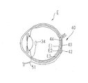
図5は、刺激部40を眼内に埋植した状態を示す概略図である。対向電極34は図示するように眼内中央の前眼部寄りの位置に置かれる。これによって、網膜E1は電極44と対向電極34(対向電極)との間に位置することとなる。電極44からの電気刺激パルス信号電流が効率的に網膜を貫通することとなる。   FIG. 5 is a schematic view showing a state in which the stimulating unit 40 is implanted in the eye. The counter electrode 34 is placed at a position near the anterior eye part in the center of the eye as shown in the figure. As a result, the retina E1 is positioned between the electrode 44 and the counter electrode 34 (counter electrode). The electrical stimulation pulse signal current from the electrode 44 efficiently penetrates the retina.

一方、受信手段31は、体外装置10に設けられた送信手段14からの信号(電気刺激パルス用データ及び電力)を受信可能な生体内の所定位置に設置される。例えば、図1に示すように、患者の側頭部の皮膚の下に受信部30(図では受信手段31のみ示している)を埋め込むとともに、皮膚を介して受信部30と対向する位置に送信手段14を設置しておく。受信部30には、送信手段14と同様に磁石が取り付けられているため、埋植された受信部30上に送信手段14を位置させることにより、磁力によって送信手段14と受信部30とが引き合い、送信手段14が側頭部に保持されることとなる。   On the other hand, the receiving means 31 is installed at a predetermined position in the living body that can receive signals (electric stimulation pulse data and power) from the transmitting means 14 provided in the extracorporeal device 10. For example, as shown in FIG. 1, the receiving unit 30 (only the receiving unit 31 is shown in the figure) is embedded under the skin of the patient's temporal region and transmitted to a position facing the receiving unit 30 through the skin. The means 14 is installed. Since the magnet is attached to the receiver 30 in the same manner as the transmitter 14, the transmitter 14 and the receiver 30 are attracted by the magnetic force by positioning the transmitter 14 on the implanted receiver 30. The transmission means 14 is held on the temporal region.

なお、ワイヤ50を束ねたケーブル51は、側頭部に埋め込まれた受信部30から側頭部に沿って皮膚下を患者眼に向かって延び、患者の上まぶたの内側を通して眼窩に入れられる。眼窩に入れられたケーブル51は、図5に示すように強膜E3の外側を通り、基板43に設置された刺激制御部42に接続される。   The cable 51 in which the wires 50 are bundled extends from the receiving unit 30 embedded in the temporal region under the skin toward the patient's eye along the temporal region, and is inserted into the eye socket through the inside of the patient's upper eyelid. As shown in FIG. 5, the cable 51 placed in the eye socket passes through the outer side of the sclera E <b> 3 and is connected to the stimulation control unit 42 installed on the substrate 43.

なお、本実施形態では、体内装置20(刺激部40)の設置位置を強膜E3側に位置させて、強膜E3側(脈絡膜側)から網膜E1を構成する細胞を電気刺激する構成としたが、これに限るものではない。電極を配置する基板がフレキシブルであることが好ましい部位で患者眼の網膜を構成する細胞を好適に刺激することが可能な位置に電極を設置することができればよい。例えば、層間に電極及び基板を設置すればよい。体内装置を患者眼の眼内(網膜上や網膜下)に置き、電極が形成されている基板先端部分を網膜下(網膜と脈絡膜との間)や網膜上に設置させるような構成とすることもできる。   In the present embodiment, the position where the intracorporeal device 20 (stimulation unit 40) is installed is located on the sclera E3 side, and the cells constituting the retina E1 are electrically stimulated from the sclera E3 side (choroid side). However, it is not limited to this. It is only necessary that the electrode can be placed at a position where the cells constituting the retina of the patient's eye can be suitably stimulated at a site where the substrate on which the electrode is placed is preferably flexible. For example, an electrode and a substrate may be provided between the layers. The internal device is placed in the eye of the patient (on the retina or subretinal) and the tip of the substrate on which the electrode is formed is placed under the retina (between the retina and choroid) or on the retina. You can also.

以上のような構成を備える視覚再生補助装置において、その動作を図6に示す制御系のブロック図を基に説明する。図1に示す撮影装置12により撮影された被写体の撮影データ(画像データ)は、データ変調手段13aに送られる。データ変調手段13aは、撮影した被写体を患者が認識するために必要となる所定のデータパラメータ(電気刺激パルス用データ)に変換し、さらに電磁波として伝送するのに適した変調信号を生成し、送信手段14より電磁波として体内装置20側に送信する。   The operation of the visual reproduction assisting apparatus having the above configuration will be described with reference to the control system block diagram shown in FIG. The photographing data (image data) of the subject photographed by the photographing device 12 shown in FIG. 1 is sent to the data modulation means 13a. The data modulation means 13a converts the photographed subject into predetermined data parameters (electric stimulation pulse data) necessary for the patient to recognize, and further generates and transmits a modulation signal suitable for transmission as an electromagnetic wave. The electromagnetic wave is transmitted from the means 14 to the in-vivo device 20 side as electromagnetic waves.

また同時に、データ変調手段13aは、バッテリ13bから供給されている電力を前述した変調信号(電気刺激パルス用データ)の帯域と異なる帯域の電磁波として前記変調信号と合わせて体内装置20側に送信する。   At the same time, the data modulation means 13a transmits the power supplied from the battery 13b to the in-vivo device 20 side together with the modulation signal as an electromagnetic wave having a band different from the band of the modulation signal (electric stimulation pulse data) described above. .

体内装置20側では、体外装置10より送られてくる変調信号と電力とを受信手段31にて受け取り、制御部32に送る。制御部32では受けとった信号から、変調信号が使用する帯域の信号を抽出するとともに、この変調信号に基づいて電気刺激パルス用パラメータ信号と制御信号とを形成し、電極指定信号である制御信号を刺激制御部42に送信する。   On the in-vivo device 20 side, the modulation signal and power sent from the extracorporeal device 10 are received by the receiving means 31 and sent to the control unit 32. The control unit 32 extracts a signal in a band used by the modulation signal from the received signal, forms an electrical stimulation pulse parameter signal and a control signal based on the modulation signal, and generates a control signal as an electrode designation signal. It transmits to the stimulus control unit 42.

刺激制御部42は、受け取った信号に基づき電力及び制御信号を抽出する。刺激制御部42は、制御信号に基づき制御部32から供給される電気刺激パルス信号を各電極44に分配し、出力させる。各電極44から出力される電気刺激パルス信号によって網膜E1を構成する細胞が電気刺激され、患者は視覚(擬似光覚)を得る。なお、制御部32は、受信手段31により体内装置20を駆動させるための電力を得る。   The stimulus control unit 42 extracts power and a control signal based on the received signal. The stimulation control unit 42 distributes the electrical stimulation pulse signal supplied from the control unit 32 to each electrode 44 based on the control signal, and outputs it. The cells constituting the retina E1 are electrically stimulated by the electrical stimulation pulse signal output from each electrode 44, and the patient obtains vision (pseudo light sensation). The control unit 32 obtains electric power for driving the in-vivo device 20 by the receiving unit 31.

なお、以上説明した本実施形態では、患者眼の強膜E3に基板43を設置し、強膜E3を介して網膜E1を電気刺激する構成としたが、これに限るものではない。患者の視覚を形成する視覚神経系を構成する細胞又は組織を電気的に刺激する構成であればよい。例えば、電気刺激パルス信号を出力する電極を有する刺激部を眼内の視神経乳頭部や眼外の視神経部分に配置し、刺激部への電力供給や指令信号を送る送信部を患者の皮下等の離れた場所に配置して、視神経を電気刺激する構成としてもよい。また、電極を有する刺激部を視交叉や外側膝状体、大脳皮質等の視覚神経系の高次視覚処理を行う組織に配置し、それぞれの組織を構成する細胞を刺激する構成としてもよい。例えば、大脳皮質の後頭葉であれば、錐体細胞等を刺激する又は視覚野V1、V2等を刺激する等である。また、以上説明した本実施形態では、撮像装置からの画像データをデータ変調手段にて所定の信号に変換し、送信手段にて信号を体内へと送る体外装置と、体外装置からの信号を受信手段にて受け、その信号に基づいて各電極から電気刺激パルス信号を出力する体内装置と、で構成される体外撮像型の視覚再生捕縄装置を例に挙げたがこれに限るものではない。眼内に撮像装置やデータ変調手段等を埋植する体内撮像型の視覚再生補助装置であってもよい。   In the embodiment described above, the substrate 43 is placed on the sclera E3 of the patient's eye and the retina E1 is electrically stimulated via the sclera E3. However, the present invention is not limited to this. Any structure may be used as long as it electrically stimulates cells or tissues constituting the visual nervous system that forms the vision of the patient. For example, a stimulation unit having an electrode for outputting an electrical stimulation pulse signal is arranged in the optic nerve head in the eye or the optic nerve part outside the eye, and a transmission unit for supplying power to the stimulation unit or sending a command signal is used for the subcutaneous part of the patient. It is good also as a structure which arrange | positions in a distant place and electrically stimulates an optic nerve. Alternatively, a stimulating unit having electrodes may be arranged in a tissue that performs higher-order visual processing of the visual nervous system such as the optic chiasm, outer knee, and cerebral cortex, and stimulates the cells that constitute each tissue. For example, in the case of the occipital lobe of the cerebral cortex, it stimulates pyramidal cells or the like, or stimulates the visual cortex V1, V2, etc. In the present embodiment described above, the image data from the imaging device is converted into a predetermined signal by the data modulation means, and the signal is sent from the transmission means to the inside of the body, and the signal from the extracorporeal device is received. An example of an external imaging type visual reproduction trapping device that includes an in-vivo device that receives an electrical stimulation pulse signal from each electrode based on the signal is given as an example. However, the present invention is not limited thereto. It may be an in-vivo imaging type visual reproduction auxiliary device in which an imaging device, data modulation means, etc. are implanted in the eye.

視覚再生補助装置の外観を示した概略図である。It is the schematic which showed the external appearance of the visual reproduction auxiliary | assistance apparatus. 本実施形態における視覚再生補助装置の体内装置を示した概略図である。It is the schematic which showed the in-vivo apparatus of the visual reproduction assistance apparatus in this embodiment. 電極44付近の模式的断面図である。3 is a schematic cross-sectional view in the vicinity of an electrode 44. FIG. 電極44を作製する手順を模式的に示した図である。It is the figure which showed the procedure which produces the electrode 44 typically. 体内装置を体内に設置した状態を示した図である。sIt is the figure which showed the state which installed the in-vivo apparatus in the body. s 本実施形態における視覚再生補助装置の制御系を示したブロック図である。It is the block diagram which showed the control system of the visual reproduction auxiliary | assistance apparatus in this embodiment. 電極44の作製方法の変容例を説明する図である。It is a figure explaining the modification of the preparation methods of the electrode.

符号の説明Explanation of symbols

1 視覚再生補助装置
10 体外装置
20 体内装置
30 受信部
31 受信手段
32 制御部
34 対向電極
40 刺激部
41 ワイヤ
42 刺激制御部
43 基板
44 電極
45 台座
46 ワッシャ
50 ワイヤ
51 ケーブル
DESCRIPTION OF SYMBOLS 1 Visual reproduction | regeneration assistance apparatus 10 External apparatus 20 In-vivo apparatus 30 Receiving part 31 Receiving means 32 Control part 34 Counter electrode 40 Stimulation part 41 Wire 42 Stimulation control part 43 Board | substrate 44 Electrode 45 Base 46 Washer 50 Wire 51 Cable

Claims (7)

所定の基板に形成された複数の導線の先端に各々形成される電極と、患者の視覚を形成する視覚神経系を構成する細胞又は組織を電気刺激するために前記導線を介して前記電極から電気刺激パルス信号を出力させる制御手段と、を備える視覚再生補助装置において、
前記電極は、前記導線の先端に接続され前記基板上に凸状に形成される第1電極と、該第1電極の径よりも大きな第2電極であって,前記第1電極の先端部に接合される第2電極とからなることを特徴とする視覚再生補助装置。
Electrodes formed on the tips of a plurality of conductors formed on a predetermined substrate, and electricity from the electrodes via the conductors to electrically stimulate cells or tissues constituting the visual nervous system that forms the vision of the patient A visual reproduction assisting device comprising: control means for outputting a stimulation pulse signal;
The electrodes are a first electrode connected to the tip of the conducting wire and formed in a convex shape on the substrate, and a second electrode larger than the diameter of the first electrode, and the tip of the first electrode A visual reproduction assisting device comprising a second electrode to be joined.
請求項1の視覚再生補助装置において、前記第2電極は、前記第1電極の少なくとも先端と嵌合するための凹部又は貫通孔が形成されており、前記第1電極に第2電極をを嵌合させた状態でかしめることにより一の電極として一体化されていることを特徴とする視覚再生補助装置。 2. The visual reproduction assisting device according to claim 1, wherein the second electrode is formed with a recess or a through hole for fitting with at least a tip of the first electrode, and the second electrode is fitted into the first electrode. A visual reproduction assisting device which is integrated as one electrode by caulking in a combined state. 請求項1の視覚再生補助装置において、前記第2電極は、前記第1電極の先端部にかしめられることにより、前記第1電極と前記第2電極とで前記基板を挟持することを特徴とする視覚再生補助装置。 2. The visual reproduction assisting device according to claim 1, wherein the second electrode clamps the substrate between the first electrode and the second electrode by being caulked to a tip portion of the first electrode. Visual reproduction assist device. 請求項1の視覚再生補助装置において、前記第1電極は前記フレキシブル基板を貫通する柱状部材と、該柱状部材の基部に形成される基台であって,前記基板から前記第1電極が脱落することを防ぐ程度の大きさに形成された基台と、からなることを特徴とする視覚再生補助装置。 2. The visual reproduction assisting device according to claim 1, wherein the first electrode is a columnar member penetrating the flexible substrate and a base formed at a base portion of the columnar member, and the first electrode is dropped from the substrate. A visual reproduction assisting device comprising: a base formed in a size that prevents such a situation. 請求項1の視覚再生補助装置において、前記導線は、生体適合性を有すると共に絶縁性を有する素材にて被覆されていることを特徴とする視覚再生補助装置。 2. The visual reproduction assisting device according to claim 1, wherein the conducting wire is covered with a material having biocompatibility and insulating properties. 請求項1の視覚再生補助装置において、前記基板は、前記第1電極の先端部が貫通される貫通孔を有する第1基板と、前記第1電極を前記第1基板とで挟持する第2基板とで構成されることを特徴とする視覚再生補助装置。 2. The visual reproduction assisting device according to claim 1, wherein the substrate includes a first substrate having a through-hole through which a tip end portion of the first electrode passes, and a second substrate sandwiching the first electrode with the first substrate. A visual reproduction assisting device characterized by comprising: 請求項6の視覚再生補助装置において、前記導線は、生体適合性を有すると共に絶縁性を有する素材にて被覆されており、該導線は、前記第1電極の先端に接続されると共に、第1基板と第2基板とで挟持されることを特徴とする視覚再生補助装置。 7. The visual reproduction assisting device according to claim 6, wherein the conducting wire is covered with a material having biocompatibility and insulating properties, and the conducting wire is connected to a tip of the first electrode, and is connected to the first electrode. A visual reproduction assisting device that is sandwiched between a substrate and a second substrate.
JP2007256644A 2007-09-28 2007-09-28 Sight regeneration aid Pending JP2009082496A (en)

Priority Applications (1)

Application Number Priority Date Filing Date Title
JP2007256644A JP2009082496A (en) 2007-09-28 2007-09-28 Sight regeneration aid

Applications Claiming Priority (1)

Application Number Priority Date Filing Date Title
JP2007256644A JP2009082496A (en) 2007-09-28 2007-09-28 Sight regeneration aid

Publications (1)

Publication Number Publication Date
JP2009082496A true JP2009082496A (en) 2009-04-23

Family

ID=40656749

Family Applications (1)

Application Number Title Priority Date Filing Date
JP2007256644A Pending JP2009082496A (en) 2007-09-28 2007-09-28 Sight regeneration aid

Country Status (1)

Country Link
JP (1) JP2009082496A (en)

Cited By (1)

* Cited by examiner, † Cited by third party
Publication number Priority date Publication date Assignee Title
JP2010279540A (en) * 2009-06-04 2010-12-16 Nidek Co Ltd Visual reproduction assisting apparatus

Cited By (1)

* Cited by examiner, † Cited by third party
Publication number Priority date Publication date Assignee Title
JP2010279540A (en) * 2009-06-04 2010-12-16 Nidek Co Ltd Visual reproduction assisting apparatus

Similar Documents

Publication Publication Date Title
JP4970069B2 (en) Visual reproduction assist device
JP2007044323A (en) Eyesight regeneration supporting apparatus
JP5899814B2 (en) Implantation device
EP1894599A1 (en) Vision regeneration assisting apparatus
CN109364368B (en) Stimulating electrode structure of artificial retina and artificial retina
US7844329B2 (en) Implantable electrical connector
JP2011030734A (en) Visual restoration aiding device and method of manufacturing the same
CN102123760A (en) Strain relief in an implantable electrode assembly
JP2007236409A (en) Visual sense regeneration assisting apparatus
JP5405848B2 (en) Visual reproduction assist device
JP2004195206A6 (en) Method for producing electrode for stimulating biological tissue and electrode for stimulating biological tissue obtained by the method
JP2004195206A (en) Method of manufacturing biological tissue stimulating electrode and biological tissue stimulating electrode obtained by this method
JP2006034427A (en) Visual restoration aiding device
JP5219443B2 (en) Method for producing stimulation unit for visual reproduction assist device
JP5122244B2 (en) Visual reproduction assist device
US8880179B2 (en) Vision regeneration assist apparatus and implantable apparatus
JP2006280412A (en) Auxiliary device for regenerating visual sense and method of manufacturing
JP2009082496A (en) Sight regeneration aid
JP5188792B2 (en) Visual reproduction assist device
JP6357752B2 (en) Manufacturing method of visual reproduction assist device
JP5265209B2 (en) Visual reproduction assist device
JP4162526B2 (en) Visual reproduction assist device
CN206198475U (en) The stimulating electrode structure and artificial retina of artificial retina
JP2008245834A (en) Vision regeneration assisting device, and conducting wire connecting method of vision regeneration assisting device
JP5284027B2 (en) Visual reproduction assist device