JP2009062124A - Automatic teaching method for stacker crane - Google Patents
Automatic teaching method for stacker crane Download PDFInfo
- Publication number
- JP2009062124A JP2009062124A JP2007230059A JP2007230059A JP2009062124A JP 2009062124 A JP2009062124 A JP 2009062124A JP 2007230059 A JP2007230059 A JP 2007230059A JP 2007230059 A JP2007230059 A JP 2007230059A JP 2009062124 A JP2009062124 A JP 2009062124A
- Authority
- JP
- Japan
- Prior art keywords
- transfer machine
- transfer
- stacker crane
- shelf
- sensor
- Prior art date
- Legal status (The legal status is an assumption and is not a legal conclusion. Google has not performed a legal analysis and makes no representation as to the accuracy of the status listed.)
- Granted
Links
Images


Abstract
Description
本発明は、スタッカクレーンの自動ティーチング方法に関し、特に、スタッカクレーンを配設した自動倉庫において、自動倉庫内の列方向及び上下方向に配設されたカセット収納用の各収納棚に対し、スタッカクレーンに搭載した移載機によるカセットの出し入れを正確に行えるよう、定位置に停止したスタッカクレーンの移載機アームの突出位置及びその突出量を、設定値に自動的に調整できるようにしたスタッカクレーンの自動ティーチング方法に関するものである。 The present invention relates to an automatic teaching method for a stacker crane, and in particular, in an automatic warehouse provided with a stacker crane, the stacker crane is provided for each storage shelf for storing cassettes arranged in a row direction and a vertical direction in the automatic warehouse. A stacker crane that can automatically adjust the protruding position and the protruding amount of the transfer machine arm of the stacker crane stopped at a fixed position to the set value so that the cassette can be taken in and out accurately by the transfer machine mounted on the machine. This relates to an automatic teaching method.
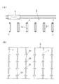
従来、例えば、図6に示すように、液晶パネル製造ラインにおいては、図8に示すように、搬送ラインRに沿って複数の自動倉庫Sを配設し、かつ該各自動倉庫S、S間を搬送ラインRに沿って走行する搬送台車OHVにてガラス薄板等の薄い基板(以下、「液晶パネル」と称する。)をカセット内に収納し、このカセット毎搬送するようにし、さらに各自動倉庫外の片側或いは両側に複数の加工装置EQを配置し、この複数の加工装置EQ間を移送して所要の液晶パネルを加工或いは製造するようにしている。 Conventionally, for example, as shown in FIG. 6, in a liquid crystal panel manufacturing line, as shown in FIG. 8, a plurality of automatic warehouses S are arranged along the transfer line R, and between the automatic warehouses S, S. A thin substrate such as a glass thin plate (hereinafter referred to as “liquid crystal panel”) is stored in a cassette by a transport cart OHV traveling along the transport line R, and is transported for each cassette. A plurality of processing devices EQ are arranged on one or both sides of the outside, and a required liquid crystal panel is processed or manufactured by transferring between the plurality of processing devices EQ.
また、この自動倉庫内には、自動倉庫内を走行するスタッカクレーンCと、液晶パネルを収納したカセットを保管するようにした複数の収納棚S1、S2、S3、・・・、Snとを備え、スタッカクレーンCにて前記各加工装置EQ間の移送と、所定の収納棚へのカセットを受け渡しによる移載とを行うようにしている。
このスタッカクレーンCの走行、スタッカクレーンに備えた移載機によるカセットの収納棚及び加工装置EQへの受け渡し、移載カセットの各収納棚への位置合わせ等の動作は、予め組み込まれたプログラムによりスタッカクレーンCを制御し、自動運転できるようにしている。
In addition, the automatic warehouse includes a stacker crane C that travels in the automatic warehouse, and a plurality of storage shelves S1, S2, S3,..., Sn that store cassettes that store liquid crystal panels. The stacker crane C performs transfer between the processing devices EQ and transfer by transferring the cassette to a predetermined storage shelf.
Operations such as travel of the stacker crane C, transfer of cassettes to the storage shelves and processing equipment EQ by the transfer machine provided in the stacker crane, and positioning of the transfer cassettes to the respective storage shelves are carried out by a pre-installed program. The stacker crane C is controlled to enable automatic operation.
ところで、近年、液晶パネルを収納したカセットをより多く収納するために、図7に示すように、自動倉庫内には上下方向に対して多段式に、またスタッカクレーンの走行方向に沿った列方向に対しては複数列に多数の収納棚S1、S2、S3、・・・、Snを配設するように構成するとともに、カセットのサイズに合わせて収納棚の上下方向及び横方向の隙間は可及的に少なく設定されている。このため、スタッカクレーンCの位置合わせは、各収納棚毎に寸分の狂いもなく正確に行わねば伸張する移載機アームの先端が収納棚の一部或いは柱と衝突する虞がある。
また、カセットの搬送及びその受け渡しのサイクルタイムを短縮して移載効率を向上させるため、受け渡しを行う収納棚と、これと対峙する所定位置で停止したスタッカクレーンから移載機アームを、速やかに自動的に所定の収納棚に伸張させる必要がある。
By the way, in recent years, in order to store more cassettes that store liquid crystal panels, as shown in FIG. 7, in an automatic warehouse, in a multistage manner with respect to the vertical direction, and in a row direction along the running direction of the stacker crane In contrast, a plurality of storage shelves S1, S2, S3,..., Sn are arranged in a plurality of rows, and the vertical and horizontal clearances of the storage shelves are allowed according to the size of the cassette. As few as possible. For this reason, if the stacker crane C is positioned accurately for each storage shelf without any deviation, there is a possibility that the tip of the transfer machine arm that extends will collide with a part of the storage shelf or a column.
In addition, in order to shorten the cycle time for transporting and transferring cassettes and to improve transfer efficiency, the transfer machine arm is quickly moved from the storage shelf for transfer and the stacker crane stopped at a predetermined position facing it. It is necessary to automatically extend to a predetermined storage shelf.
そして、自動倉庫を新設したとき等において、スタッカクレーンを実働させる前に、予め各収納棚位置における移載機アームの出没する高さ方向及び横方向(X軸、Y軸)の位置と、その突出量等を設定し、そのデータをスタッカクレーンを制御する制御装置に入力し、このデータに基づき、スタッカクレーンを自動運転するようにしている。 And when the automatic warehouse is newly established, before actually operating the stacker crane, the height direction and lateral direction (X axis, Y axis) where the transfer machine arm appears and disappears in each storage shelf position in advance, The amount of protrusion is set and the data is input to a control device that controls the stacker crane, and the stacker crane is automatically operated based on this data.
ところが、このスタッカクレーンの制御データは、作業者が各収納棚毎に、スタッカクレーンを予め設定した定位置に停止させ、該位置で移載機アームの高さ方向及び横方向の位置と、その突出量等を手動にて確認しつつ正確に調整して得るようにしているので、その位置合わせに多大の時間と労力を要するという問題があった。 However, the control data of the stacker crane is obtained by the operator stopping the stacker crane at a preset position for each storage shelf, and the height and lateral positions of the transfer machine arm at the position, Since the amount of protrusion and the like are adjusted and obtained accurately while being manually checked, there is a problem that much time and labor are required for the alignment.
本発明は、上記従来のスタッカクレーンの位置合わせ操作に有する問題点に鑑み、移載機アームが自動倉庫内の棚受けや柱に衝突することがない、予め設定した定位置にて突出して収納棚の定位置に載置できるよう、各収納棚位置における移載機アームの出没高さ及び横方向の位置の制御データを自動的に得られるようにしたスタッカクレーンの自動ティーチング装置を提供することを目的とする。 In view of the problems in the positioning operation of the conventional stacker crane, the present invention protrudes and stores at a predetermined fixed position where the transfer machine arm does not collide with a shelf holder or a pillar in an automatic warehouse. To provide an automatic teaching device for a stacker crane capable of automatically obtaining control data of the height and lateral position of a transfer machine arm at each storage shelf position so that it can be placed at a fixed position on the shelf. With the goal.
上記目的を達成するため、本発明のスタッカクレーンの自動ティーチング方法は、自動倉庫に、カセットを保管する多段式の棚を形成する柱側には、各棚における移載機アーム突出位置の上部と下部を個別に検出するための検出マーカを、移載機側には該上下の各検出マーカを検知するための複数の光センサをそれぞれ備え、各検出マーカの定位置で複数センサの光軸を同時に検知した位置を、出没する移載機アームの高さ方向及び横方向(X軸、Y軸)の位置データとし、これをデータ化して移載機アームの突出位置を設定するように構成したことを特徴とする。 In order to achieve the above object, the stacker crane automatic teaching method according to the present invention has an automatic warehouse in which a multi-stage shelf for storing cassettes is formed on the column side, and an upper portion of a transfer machine arm protruding position on each shelf is provided. A detection marker for individually detecting the lower part is provided, and a plurality of optical sensors for detecting the upper and lower detection markers are provided on the transfer machine side, and the optical axes of the plurality of sensors are set at fixed positions of the respective detection markers. The position detected at the same time is used as position data in the height direction and lateral direction (X axis, Y axis) of the transfer machine arm that appears and disappears, and this is converted into data to set the protruding position of the transfer machine arm. It is characterized by that.
この場合において、移載機側に配設する光センサを、3個1組としてL字形に配設して構成することができる。 In this case, the photosensors arranged on the transfer machine side can be arranged in an L shape as a set of three.
また、検出マーカを、L字形に配設した3個1組の光センサの光軸を定位置にて同時に受けたとき、左右に対峙して配設した2つの光センサの光軸から検出マーカ側端縁までの距離及び上下に配設した2つの光センサの光軸から検出マーカの上下端縁までの距離を等しくなるよう、その大きさを設定することができる。 Further, when the detection markers are simultaneously received at a fixed position by a set of three photosensors arranged in an L shape, the detection markers are detected from the optical axes of the two photosensors arranged facing left and right. The size can be set so that the distance to the side edge and the distance from the optical axis of the two photosensors arranged above and below to the upper and lower edges of the detection marker are equal.
本発明のスタッカクレーンの自動ティーチング方法によれば、自動倉庫に、カセットを保管する多段式の棚を形成する柱側には、各棚における移載機アーム突出位置の上部と下部を個別に検出するための検出マーカを、移載機側には該上下の各検出マーカを検知するための複数の光センサをそれぞれ備え、各検出マーカの定位置で複数センサの光軸を同時に検知した位置を、出没する移載機アームの高さ方向及び横方向(X軸、Y軸)の位置データとし、これをデータ化して移載機アームの突出位置を設定するように構成することにより、各棚に対する移載機アームのずれが左右いずれの側方向と上下方向に、かつそのいずれのずれ量が正確に検知することができるので、相対位置関係が正確に、迅速に自動調整することができる。 According to the automatic teaching method of the stacker crane of the present invention, the upper side and the lower side of the transfer machine arm protruding position in each shelf are individually detected on the column side forming the multistage shelf for storing cassettes in the automatic warehouse. And a plurality of optical sensors for detecting the upper and lower detection markers on the transfer machine side, respectively, and the positions where the optical axes of the plurality of sensors are simultaneously detected at the fixed positions of the respective detection markers. By setting the projecting position of the transfer machine arm as the position data in the height direction and the horizontal direction (X axis, Y axis) of the transfer machine arm that appears and that is converted into data, each shelf Since the shift of the transfer machine arm relative to the left and right sides and the vertical direction can be accurately detected, and the amount of any shift can be accurately detected, the relative positional relationship can be accurately and quickly adjusted automatically.
また、移載機側に配設する光センサを、3個1組としてL字形に配設して構成することにより、簡単な構成で移載機アームのずれ方向とその量を検知することができる。 In addition, by arranging the optical sensors arranged on the transfer machine side in an L shape as a set of three, it is possible to detect the shift direction and the amount of the transfer machine arm with a simple configuration. it can.
また、検出マーカを、L字形に配設した3個1組の光センサの光軸を定位置にて同時に受けたとき、左右に対峙して配設した2つの光センサの光軸から検出マーカ側端縁までの距離及び上下に配設した2つの光センサの光軸から検出マーカの上下端縁までの距離を等しくなるよう、その大きさを設定することにより、ずれが検知された場合、移載機アームの調整移動量を少なくして行えるので、調整が迅速に行うことができる。 Further, when the detection markers are simultaneously received at a fixed position by a set of three photosensors arranged in an L shape, the detection markers are detected from the optical axes of the two photosensors arranged facing left and right. When deviation is detected by setting the size so that the distance to the side edge and the distance from the optical axis of the two optical sensors arranged above and below to the upper and lower edges of the detection marker are equal, Adjustment can be performed quickly because the amount of adjustment movement of the transfer arm can be reduced.
以下、本発明のスタッカクレーンの自動ティーチング方法の実施の形態を、図面に基づいて説明する。 DESCRIPTION OF EMBODIMENTS Hereinafter, an embodiment of an automatic teaching method for a stacker crane according to the present invention will be described with reference to the drawings.
図1〜図8に、本発明のスタッカクレーンの自動ティーチング方法の一実施例を示す。 1 to 8 show an embodiment of the automatic teaching method for a stacker crane of the present invention.
例えば、液晶製造装置等においては、図6に示すように、搬送ラインRに沿って複数の自動倉庫Sを配設し、かつ該各自動倉庫S、S間を搬送ラインRに沿って走行する搬送台車OHV等にて液晶パネルを収納したカセットを搬送するようにし、各自動倉庫Sに配設した複数の加工装置EQにて所要の加工を行うようにしている。
また、各自動倉庫内には、図8に示すように、自動倉庫内を走行するスタッカクレーンCと、液晶パネルを収納したカセットを保管するようにした複数の収納棚とを備え、スタッカクレーンCを加工工程に沿って走行させて前記各加工装置EQ間の移送及び受け渡しと、所定の収納棚へのカセットを受け渡しによる移載とを行うようにしている。
なお、この自動倉庫内には、図7に示すように、走行するスタッカクレーンCの走行方向に沿って片側或いは両側に、カセットを保管する複数の収納棚S1、S2、S3、・・・、Snが上下方向に複数段にして配設されている。
For example, in a liquid crystal manufacturing apparatus or the like, as shown in FIG. 6, a plurality of automatic warehouses S are arranged along the transfer line R, and the automatic warehouses S and S travel along the transfer line R. A cassette containing a liquid crystal panel is transported by a transport cart OHV or the like, and required processing is performed by a plurality of processing devices EQ disposed in each automatic warehouse S.
In addition, as shown in FIG. 8, each automatic warehouse includes a stacker crane C that travels in the automatic warehouse and a plurality of storage shelves that store cassettes that store liquid crystal panels. Are moved along the machining process to transfer and transfer between the processing devices EQ and transfer by transferring the cassette to a predetermined storage shelf.
In this automatic warehouse, as shown in FIG. 7, a plurality of storage shelves S1, S2, S3,... For storing cassettes on one side or both sides along the traveling direction of the traveling stacker crane C. Sn is arranged in a plurality of stages in the vertical direction.
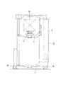
この液晶パネル搬送用のスタッカクレーンCは、例えば、図8に示すように、自動倉庫Sの床面等に配設した走行レールに沿って走行可能とし、かつ速度及び停止位置を制御できるようにした走行台車1の上部に、門形等をした所要長のメインマスト2を樹立するようにして取り付け、このメインマスト2に昇降台3を昇降可能に取り付けるとともに、該昇降台3には出没してカセットを移載するように、図1に示すように、屈伸旋回或いは伸縮可能した複数本の移載用アーム4a、4aと移載用フォーク4bとを組み合わせてなる移載機4を搭載して構成するようにしている。
この走行台車1は、その下部に走行用の電動モータにより低速又は可変速可能に、かつ安定走行を行うよう、走行レールに沿って回転駆動される複数の走行車輪Wよりなる走行駆動装置を配設して構成する。この昇降台3の昇降方式は、特に限定されるものではないが、例えば、図示の実施例のように、メインマスト2をガイドとしてバランスウェイトを備えた索条をドラムの回転により、該索条の巻き上げ、巻き戻しにより、平面的に定位置で微調整可能にして昇降するようにする。
なお、この移載機4に配設する移載用アーム4a、4aは、屈伸旋回式として走行台車1の走行方向に沿ってその側方に対峙するよう配設した自動倉庫の収納棚S1、S2、S3、・・・、Snに向かって移載用フォーク4bを突出(伸張)するようにして、スタッカクレーンCと自動倉庫Sの収納棚間においてのカセットKの受け渡しにより移載するようにする。
For example, as shown in FIG. 8, the stacker crane C for transporting the liquid crystal panel can travel along a traveling rail disposed on the floor surface of the automatic warehouse S, and can control the speed and stop position. A
The traveling
In addition, the
また、スタッカクレーンを走行可能に配設する自動倉庫Sは、図7に示すように、複数の収納棚S1、S2、S3、・・・、Snを上下に多段式に、かつ走行する走行台車1の走行方向に沿った列方向にも多数配設するようにして構成するが、この収納棚の段数、列数は特に限定されるものではない。
この多段式とする収納棚S1、S2、S3、・・・、Snの上下方向の間隔、及び柱間の横方向の間隔は、棚上に載置して一時的に保管するカセットKのサイズに合わせて設定するようにするが、図7に示すように、この収納棚S1、S2、S3、・・・、Snは自動倉庫S内を走行する走行台車1の走行方向に沿った片側に、或いは両側に配置することができる。
なお、この各段の収納棚S1、S2、S3、・・・、Snは、カセットKのサイズに合わせて設定した間隔毎に配設する自動倉庫の柱7、7の両側に、それぞれ水平位置にて対向するように突設して構成し、該各収納棚S1、S2、S3、・・・、Sn上に各カセットKを載置できるようにする。
また、多段式に収納棚S1、S2、S3、・・・、Snを形成する互いに対峙するよう配設した柱7、7と、移載機4とには移載用フォーク4bが予め設定した定位置にて出没するよう位置合わせをするための自動ティーチング装置を備える。
In addition, as shown in FIG. 7, the automatic warehouse S in which the stacker crane is allowed to run is a traveling cart that travels in a multistage manner with a plurality of storage shelves S1, S2, S3,. Although a large number of rows are arranged in the row direction along the one traveling direction, the number of rows and the number of rows of the storage shelves are not particularly limited.
The vertical intervals of the storage shelves S1, S2, S3,..., Sn, and the horizontal intervals between the columns are the size of the cassette K placed on the shelf and temporarily stored. However, as shown in FIG. 7, the storage shelves S1, S2, S3,..., Sn are on one side along the traveling direction of the traveling
In addition, the storage shelves S1, S2, S3,..., Sn of the respective stages are respectively positioned horizontally on both sides of the
In addition, the
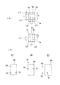
この自動ティーチング装置は、柱7側で各段の棚の上部と下部位置に配設する2つの検出マーカ6a、6bと、移載機4側に配設する基準センサ51、上センサ52及び横センサ53よりなる光センサ5とより構成する。
この検出マーカ6a、6bは、移載用フォーク4bにてカセットの移載をする際、移載用フォークの各段の収納棚S1、S2、S3、・・・、Snの位置において、収納棚より予め設定した下方の下側位置(移載用フォークの各段の棚位置より少し下側の位置でカセットを移載機側から収納棚側へ移載する位置)を検出するための下側検出マーカ6bと、これより上方位置で移載用フォークにて各段の棚位置より少し持ち上げてカセットを収納棚側から移載機側へ移載する位置を検出するための上側検出マーカ6aとする。
This automatic teaching device includes two
The
この2つ1組とする上下の検出マーカ6a、6bは、所定の間隔をあけて上下に配設する。これにより、移載用フォーク4bのX軸とY軸方向の突出位置を検出する。
また、この上下の検出マーカ6a、6bは、センサとして複数の光センサを用いるが、各センサより照射される光を反射するようにした大きさの、特に限定されるものではないが、例えば、四角形の反射板又は反射式テープ(或いはシール)等の同じ構成のものを採用し、前記柱7の所定位置にビス等を用いて固定するか、或いは妄りに剥がれないようにして貼着するようにする。
なお、移載用フォーク4bのZ軸方向の突出位置を検出するための検出マーカ6cを配設するが、この検出マーカ6cもX軸、Y軸方向検知用の上下の検出マーカ6a、6bと同様の材質とする。
The upper and
The upper and
A
センサとしての光センサ5は、特に限定されるものではなく、移載機側に、詳しくは移載用フォーク4bのX軸とY軸方向の位置を検出するため、昇降台3に突設するセンサ取付台50に固定するが、この場合、移載用フォーク4bが昇降台3の左右両側に突出するようにしているならば、センサ取付台50は昇降台3の左右両側に配設するようにする。
また、この光センサ5は、例えば、図2及び図4に示すように、センサ取付台50の先端部に取り付けるもので、1つを基準センサ51とし、この垂直方向に所定間隔をあけて上センサ52を、またこの基準センサ51より水平方向に所定間隔をあけて横センサ53の3個をL字形に配設して構成するもので、これら3個を一対として使用し、その光軸5a、5b、5cが、図4(A)に示すように、上下の検出マーカ6a、6bにて反射するようにする。
この場合、基準センサ51と上センサ52との間隔L1、及び基準センサ51と横センサ53との間隔L2をそれぞれ所定間隔、これは特に限定されるものではないが、例えば、間隔L1を20mm、間隔L2を12.4mmと設定し、これはカセットの大きさやティーチングの精度等により設定するものとする。
The
Further, as shown in FIGS. 2 and 4, for example, the
In this case, the interval L1 between the
なお、上下の検出マーカ6a、6bの大きさ及び形状は、図3及び図4に示すように、通常四角形のものとし、かつ光センサ5(基準センサ51、上センサ52、横センサ53)の3つの光センサ5の3本の光軸5a、5b、5cを同時に上側検出マーカ6a或いは下側検出マーカ6bの所定位置にて受けたとき、基準センサ51と上センサ52の右側方端までの距離L21及び横センサ53の左側方端までの距離L21が同じようになるようにし、かつこの距離L21は間隔L2よりも小となる距離(特に限定されるものではないが、例えば、11.3mm)となるように、また基準センサ51と横センサ53の下端までの距離及び上センサ52の上端までの距離を、間隔L1よりも小となる距離L11(特に限定されるものではないが、例えば、10mm)となるようにして大きさを設定する。
なお、距離L21は上下の検出マーカ6a、6bとも同じ大きさとし、距離L11は上下の検出マーカ6a、6bとも同じとするが、場合によっては図4(A)に示すように、下側検出マーカ6bにおいては上センサ52の上端までの距離を、前記距離L11よりも小なる距離(特に限定されるものではないが、例えば、距離L21の約半分程度の4mm)とすることができる。
これにより、移載機4の自動ティーチング時、移載機4の側方のずれ方向とそのずれ量、及び上下方向のずれ及びそのずれ量を正確に検知できるようにする。
As shown in FIGS. 3 and 4, the size and shape of the upper and
The distance L21 is the same for both the upper and
Thereby, at the time of automatic teaching of the
次に、本発明のスタッカクレーンの自動ティーチング方法の作用について説明する。
ティーチングを行う棚の位置を指定して、スタッカクレーンCを走行レール(搬送ラインR)に沿ってその指定位置まで移動させるようにしてティーチングを開始する。そして、自動倉庫Sのティーチングを行う所定列の収納棚S1の位置まで走行させるとともに、昇降台を収納棚の初期設定値に移動させる。
この収納棚の初期設定値は、収納棚と同一レベル(パスレベル:移載機4の移載用フォーク4bの上面と収納棚S1の上面が同じ高さにある位置をいう。)よりも少し高めの位置、これは特に限定されるものではないが、例えば、収納棚S1のレベルであるパスレベルに26mmを加えた値となるように設定する。
また、この動作はティーチングを行う列の定位置で停止したスタッカクレーンの昇降台3を、その降下した待機位置から索条の巻き上げにより最下段の収納棚S1の初期設定値の位置まで上昇させて行う。
Next, the operation of the stacker crane automatic teaching method of the present invention will be described.
Teaching is started by designating the position of the shelf where teaching is performed and moving the stacker crane C to the designated position along the traveling rail (conveyance line R). And while making it drive | work to the position of the storage shelf S1 of the predetermined row which teaches the automatic warehouse S, an elevator stand is moved to the initial setting value of a storage shelf.
The initial setting value of the storage shelf is slightly lower than the same level as the storage shelf (pass level: a position where the upper surface of the
In this operation, the
このようにして、自動倉庫Sのティーチングを行う所定列の収納棚S1の位置で停止させる。これは通常、1列目の収納棚列位置で停止させ、最下段の収納棚S1の収納棚の位置から上方棚の順序で順次その位置調整を行うようにするが、これは特に限定されるものではなく、最上段の収納棚Snから順次下方の収納棚の順序で行うことも可能である。 In this manner, the automatic warehouse S is stopped at the position of the storage shelf S1 in the predetermined row where teaching is performed. This is normally stopped at the first storage shelf row position, and the position adjustment is performed sequentially in the order of the upper shelf from the storage shelf position of the lowermost storage shelf S1, but this is particularly limited. Instead of the above, it is also possible to carry out in the order of the storage shelves sequentially from the uppermost storage shelf Sn.
次に、光センサ5(基準センサ51、上センサ52、横センサ53)より投光すると、これと対峙するよう柱に配設した上側検出マーカ6aより光軸が反射せず各センサ51、52、53がオフ状態であれば、一度原点に移動して同じ棚で繰り返す。これにより光センサ5の光軸が上側検出マーカ6aにより反射して各センサ51、52、53がオンするよう予め調節する。このようにして、各センサ51、52、53がオンすると移載機4を走行前進させ、この前進距離が基準センサ51と上センサ52の右側方端までの距離L11と横センサ53の左側方端までの距離L11とにさらに少しの余裕を加えた距離L12以下であるか否かをチェックし、距離L12以下になるまでリトライするとともに、この距離がL12以下ならば上センサ52をオフとし、これにより移載機4の棚位置に対しての側方のずれ方向とそのずれ量を計測するとともに、正確な位置となるよう調節される。そして、この調整方法を図4(B)のB1、B2、B3に示すようにして、移載機4を左右方向へ移動して行う。
そして、各センサ51、52、53の投光及び移載機4の走行を停止し、上センサ52のオフ時の位置より後進した距離L11の位置をその棚の走行位置として登録する。
Next, when light is projected from the optical sensor 5 (the
Then, the light projection of each
次に、移載機4を距離L11だけ後進させた後、各センサ51、52、53を投光し、各センサがオンすると移載機4の降下を開始する。その降下距離が間隔L1より少しの余裕を持たせた距離L13以下であれば基準センサ51がオフすると、各センサ51、52、53の投光と移載機4の降下を停止し、基準センサ51のオフ時の位置より少し減算した位置をその棚の昇降位置として登録する。これにより、収納棚と同一レベル(パスレベル)に対して、その上下方向及びそのずれ量を計測しつつ、パスレベルよりも少し高めの位置に設定した上レベルの調整を行う。
この上レベルの調整後、移載機4を下レベル位置まで降下させ、同様にして下レベル位置における側方のずれ方向とそのずれ量及び上下方向及びそのずれ量を計測しつつ、パスレベルよりも少し低めの位置に調整する。
Next, after the
After the adjustment of the upper level, the
このようにして、L字形に配設した基準センサ51、上センサ52、横センサ53の3個のセンサより同時に上側検出マーカ6a或いは下側検出マーカ6bに向かって光を照射され、検出マーカにて反射された光軸が再び3個のセンサにそれぞれ受光されるようになるが、このとき、図4に示すように、移載機側の光センサ5と、これに対向する収納棚側の検出マーカの位置との相対位置、例えば、X軸及びY軸方向の相対位置関係が適正かどうかを、すなわち、3個の光センサ5からの光軸が下側或いは上側検出マーカの定位置より左右或いは上下のいずれかにその位置がずれているかどうかを検出マーカにて反射された光軸がそれと対向するセンサにて受光するか否かで検知する。そして、検出マーカにて反射された光軸がそれと対向するセンサにて受光しない場合、移載機4をそのずれ方向に、かつそのずれ量に応じて移動させることで、簡易にかつ迅速に調整することができる。
In this way, light is emitted from the three sensors of the
なお、より詳しい作動の説明は、図5A及び図5Bに示すようなフローチャートにより行われるが、その詳細説明は省略する。 Note that a more detailed description of the operation will be made with reference to flowcharts as shown in FIGS.
以上、本発明のスタッカクレーンの自動ティーチング方法について、実施例に基づいて説明したが、本発明は上記実施例に記載した構成に限定されるものではなく、その趣旨を逸脱しない範囲において適宜その構成を変更することができるものである。 As mentioned above, although the automatic teaching method of the stacker crane of the present invention has been described based on the embodiments, the present invention is not limited to the configurations described in the above embodiments, and the configurations thereof are appropriately made within the scope not departing from the gist thereof. Can be changed.
本発明のスタッカクレーンの自動ティーチング方法は、収納棚を備えた柱等の固定側に反射式の検出マーカを配設し、移載機側に3つの光センサをL字形に配設して、相互のX軸、Y軸の位置関係を検知するという特性を有していることから、スタッカクレーンの自動ティーチングの用途に好適に用いることができるほか、例えば、移載機、自動加工機械の用途にも用いることができる。 In the automatic teaching method of the stacker crane of the present invention, a reflective detection marker is disposed on the fixed side of a column or the like provided with a storage shelf, and three optical sensors are disposed in an L shape on the transfer machine side. Since it has the characteristic of detecting the positional relationship between the X-axis and Y-axis, it can be used suitably for automatic teaching of stacker cranes. For example, it can be used for transfer machines and automatic processing machines. Can also be used.
1 走行台車
2 メインマスト
3 昇降台
4 移載機
4a 移載用アーム
4b 移載用フォーク
5 光センサ
51 基準センサ
52 上センサ
53 横センサ
6a 上側検出マーカ
6b 下側検出マーカ
7 柱
C スタッカクレーン
K カセット
S 自動倉庫
S1、S2、S3、・・・、Sn 収納棚
1 Traveling
DESCRIPTION OF
Claims (3)
Priority Applications (1)
| Application Number | Priority Date | Filing Date | Title |
|---|---|---|---|
| JP2007230059A JP4926895B2 (en) | 2007-09-05 | 2007-09-05 | Automatic teaching method for stacker cranes |
Applications Claiming Priority (1)
| Application Number | Priority Date | Filing Date | Title |
|---|---|---|---|
| JP2007230059A JP4926895B2 (en) | 2007-09-05 | 2007-09-05 | Automatic teaching method for stacker cranes |
Publications (2)
| Publication Number | Publication Date |
|---|---|
| JP2009062124A true JP2009062124A (en) | 2009-03-26 |
| JP4926895B2 JP4926895B2 (en) | 2012-05-09 |
Family
ID=40557091
Family Applications (1)
| Application Number | Title | Priority Date | Filing Date |
|---|---|---|---|
| JP2007230059A Expired - Fee Related JP4926895B2 (en) | 2007-09-05 | 2007-09-05 | Automatic teaching method for stacker cranes |
Country Status (1)
| Country | Link |
|---|---|
| JP (1) | JP4926895B2 (en) |
Cited By (4)
| Publication number | Priority date | Publication date | Assignee | Title |
|---|---|---|---|---|
| CN103318812A (en) * | 2013-07-09 | 2013-09-25 | 京东方科技集团股份有限公司 | Pallet fork assembly for stacker, stacker and method for carrying cartridges |
| JP2016050112A (en) * | 2014-09-02 | 2016-04-11 | 株式会社ダイフク | Article conveyance equipment |
| JP2017124933A (en) * | 2015-10-30 | 2017-07-20 | トーヨーカネツソリューションズ株式会社 | Automatic high-rise warehouse |
| KR20180073985A (en) * | 2016-12-23 | 2018-07-03 | 세메스 주식회사 | Method of loading a cassette |
Citations (2)
| Publication number | Priority date | Publication date | Assignee | Title |
|---|---|---|---|---|
| JPS54100069A (en) * | 1978-01-20 | 1979-08-07 | Daifuku Co Ltd | Warehouse facilities |
| JP2005263411A (en) * | 2004-03-18 | 2005-09-29 | Hitachi Kiden Kogyo Ltd | Automatic teaching device of stacker crane |
-
2007
- 2007-09-05 JP JP2007230059A patent/JP4926895B2/en not_active Expired - Fee Related
Patent Citations (2)
| Publication number | Priority date | Publication date | Assignee | Title |
|---|---|---|---|---|
| JPS54100069A (en) * | 1978-01-20 | 1979-08-07 | Daifuku Co Ltd | Warehouse facilities |
| JP2005263411A (en) * | 2004-03-18 | 2005-09-29 | Hitachi Kiden Kogyo Ltd | Automatic teaching device of stacker crane |
Cited By (6)
| Publication number | Priority date | Publication date | Assignee | Title |
|---|---|---|---|---|
| CN103318812A (en) * | 2013-07-09 | 2013-09-25 | 京东方科技集团股份有限公司 | Pallet fork assembly for stacker, stacker and method for carrying cartridges |
| CN103318812B (en) * | 2013-07-09 | 2015-04-01 | 京东方科技集团股份有限公司 | Pallet fork assembly for stacker, stacker and method for carrying cartridges |
| JP2016050112A (en) * | 2014-09-02 | 2016-04-11 | 株式会社ダイフク | Article conveyance equipment |
| JP2017124933A (en) * | 2015-10-30 | 2017-07-20 | トーヨーカネツソリューションズ株式会社 | Automatic high-rise warehouse |
| KR20180073985A (en) * | 2016-12-23 | 2018-07-03 | 세메스 주식회사 | Method of loading a cassette |
| KR102605209B1 (en) * | 2016-12-23 | 2023-11-23 | 세메스 주식회사 | Method of loading a cassette |
Also Published As
| Publication number | Publication date |
|---|---|
| JP4926895B2 (en) | 2012-05-09 |
Similar Documents
| Publication | Publication Date | Title |
|---|---|---|
| KR101130124B1 (en) | Article transport device and method for detecting article position deviation | |
| JP4292584B2 (en) | Transfer system | |
| KR20080016461A (en) | Article storage facility and method for operating same | |
| CN113727922B (en) | Conveying device | |
| KR102000985B1 (en) | stoker apparatus having auto teaching function, and method for auto teaching thereof | |
| JP4926895B2 (en) | Automatic teaching method for stacker cranes | |
| JP5590411B2 (en) | Stacker crane | |
| JP2006206223A (en) | Automatic teaching method of stacker crane | |
| JP4401829B2 (en) | Automatic teaching device for stacker crane | |
| JP5884507B2 (en) | How to learn goods storage facilities | |
| JP2008214075A (en) | Article carrying device | |
| JP5190694B2 (en) | Learning device in article storage facility | |
| JP6879022B2 (en) | Automated warehouse system | |
| JP2007273683A (en) | Substrate transfer device, manufacturing device of display panel using it, substrate transfer method, and manufacturing method of display panel using it | |
| CN114545917A (en) | Control method of automatic conveying system | |
| KR101479934B1 (en) | Belt lifter and auto transportation system including the same | |
| JP7071835B2 (en) | Stacker crane | |
| JP5348480B2 (en) | Goods transport equipment | |
| JP2019172439A (en) | Article conveyance device | |
| JPH10120172A (en) | Conveying device for thin base plate | |
| JP5807619B2 (en) | Goods transport equipment | |
| JP2013021166A (en) | Conveyance vehicle | |
| JPH11199010A (en) | Article storage installation | |
| JPH054706A (en) | Control method for stacker crane | |
| JP2019034827A (en) | Automatic warehouse system |
Legal Events
| Date | Code | Title | Description |
|---|---|---|---|
| A621 | Written request for application examination |
Free format text: JAPANESE INTERMEDIATE CODE: A621 Effective date: 20090820 |
|
| A131 | Notification of reasons for refusal |
Free format text: JAPANESE INTERMEDIATE CODE: A131 Effective date: 20111116 |
|
| A977 | Report on retrieval |
Free format text: JAPANESE INTERMEDIATE CODE: A971007 Effective date: 20111117 |
|
| A521 | Written amendment |
Free format text: JAPANESE INTERMEDIATE CODE: A523 Effective date: 20120116 |
|
| TRDD | Decision of grant or rejection written | ||
| A01 | Written decision to grant a patent or to grant a registration (utility model) |
Free format text: JAPANESE INTERMEDIATE CODE: A01 Effective date: 20120201 |
|
| A01 | Written decision to grant a patent or to grant a registration (utility model) |
Free format text: JAPANESE INTERMEDIATE CODE: A01 |
|
| A61 | First payment of annual fees (during grant procedure) |
Free format text: JAPANESE INTERMEDIATE CODE: A61 Effective date: 20120208 |
|
| FPAY | Renewal fee payment (prs date is renewal date of database) |
Free format text: PAYMENT UNTIL: 20150217 Year of fee payment: 3 |
|
| R150 | Certificate of patent (=grant) or registration of utility model |
Free format text: JAPANESE INTERMEDIATE CODE: R150 |
|
| FPAY | Renewal fee payment (prs date is renewal date of database) |
Free format text: PAYMENT UNTIL: 20150217 Year of fee payment: 3 |
|
| S111 | Request for change of ownership or part of ownership |
Free format text: JAPANESE INTERMEDIATE CODE: R313113 |
|
| R350 | Written notification of registration of transfer |
Free format text: JAPANESE INTERMEDIATE CODE: R350 |
|
| FPAY | Renewal fee payment (prs date is renewal date of database) |
Free format text: PAYMENT UNTIL: 20150217 Year of fee payment: 3 |
|
| LAPS | Cancellation because of no payment of annual fees |