JP2009059592A - Induction heating cooking device - Google Patents
Induction heating cooking device Download PDFInfo
- Publication number
- JP2009059592A JP2009059592A JP2007226076A JP2007226076A JP2009059592A JP 2009059592 A JP2009059592 A JP 2009059592A JP 2007226076 A JP2007226076 A JP 2007226076A JP 2007226076 A JP2007226076 A JP 2007226076A JP 2009059592 A JP2009059592 A JP 2009059592A
- Authority
- JP
- Japan
- Prior art keywords
- heating coil
- unit
- light guide
- coil
- heating
- Prior art date
- Legal status (The legal status is an assumption and is not a legal conclusion. Google has not performed a legal analysis and makes no representation as to the accuracy of the status listed.)
- Granted
Links
Images
Classifications
-
- H—ELECTRICITY
- H05—ELECTRIC TECHNIQUES NOT OTHERWISE PROVIDED FOR
- H05B—ELECTRIC HEATING; ELECTRIC LIGHT SOURCES NOT OTHERWISE PROVIDED FOR; CIRCUIT ARRANGEMENTS FOR ELECTRIC LIGHT SOURCES, IN GENERAL
- H05B6/00—Heating by electric, magnetic or electromagnetic fields
- H05B6/02—Induction heating
- H05B6/06—Control, e.g. of temperature, of power
- H05B6/062—Control, e.g. of temperature, of power for cooking plates or the like
-
- H—ELECTRICITY
- H05—ELECTRIC TECHNIQUES NOT OTHERWISE PROVIDED FOR
- H05B—ELECTRIC HEATING; ELECTRIC LIGHT SOURCES NOT OTHERWISE PROVIDED FOR; CIRCUIT ARRANGEMENTS FOR ELECTRIC LIGHT SOURCES, IN GENERAL
- H05B2213/00—Aspects relating both to resistive heating and to induction heating, covered by H05B3/00 and H05B6/00
- H05B2213/07—Heating plates with temperature control means
Abstract
Description
本発明は、調理容器を誘導加熱するとともに、赤外線センサを用いて調理容器の温度を制御する誘導加熱調理器に関する。 The present invention relates to an induction heating cooker that induction-heats a cooking container and controls the temperature of the cooking container using an infrared sensor.
近年、火を使わない調理器として誘導加熱調理器が広く普及している。この誘導加熱調理器は、加熱コイルの中央下方に赤外線センサを配置し、赤外線センサからの出力に応じて制御手段によりインバータ回路を制御して加熱コイルの出力を制御している(例えば、特許文献1参照)。この誘導加熱調理器によれば、空の(被調理物が収容されていない)鍋等の調理容器を加熱すると、調理容器は、最も磁束密度が高く加熱時の発熱が大きい加熱コイル巻線の最外周と最内周の中間部の上方部分が急激に温度上昇するため、調理容器の高温部分に対する加熱出力制御の応答が遅れ、熱伝導が悪く熱容量の低い薄手のステンレス鍋等を調理容器として使用すると、鍋底が赤熱して鍋が変形したり、あるいは油等の少量の被調理物が高温となる場合があった。 In recent years, induction cooking devices have been widely used as cooking devices that do not use fire. In this induction heating cooker, an infrared sensor is arranged below the center of the heating coil, and the output of the heating coil is controlled by controlling the inverter circuit by the control means in accordance with the output from the infrared sensor (for example, Patent Documents). 1). According to this induction heating cooker, when a cooking container such as an empty pan (which does not contain the object to be cooked) is heated, the cooking container has a heating coil winding with the highest magnetic flux density and high heat generation during heating. Because the temperature of the upper part of the middle part between the outermost circumference and the innermost circumference rises suddenly, the response of the heating output control to the high temperature part of the cooking container is delayed, and a thin stainless steel pan etc. with poor heat conduction and low heat capacity is used as the cooking container. When used, the pan bottom may become red hot and the pan may be deformed, or a small amount of food such as oil may become hot.
そこで、赤外線センサを加熱コイルの中央でなく加熱コイル中間部や、あるいは加熱コイルの巻線内周近傍下方に配置する構成を採用することで、調理容器の高温部を赤外線センサで測定して感度良く容器の温度を検知することができ、その測定結果を用いて加熱コイルに供給する電力を制御することで調理容器の温度を応答よく制御することができる。その結果、少量の油の発火や薄い調理容器の高温での変形を防止することができる。 Therefore, by adopting a configuration in which the infrared sensor is arranged not in the center of the heating coil but in the middle of the heating coil or near the inner periphery of the winding of the heating coil, the high temperature part of the cooking vessel is measured by the infrared sensor and the sensitivity is measured. The temperature of the container can be detected well, and the temperature of the cooking container can be controlled with good response by controlling the power supplied to the heating coil using the measurement result. As a result, ignition of a small amount of oil and deformation of the thin cooking container at high temperatures can be prevented.
しかしながら、上記赤外線センサを加熱コイルの中央でなく加熱コイル中間部や、あるいは加熱コイルの巻線内周近傍下方に配置する誘導加熱調理器において、調理容器が載置される天板に載置された調理容器から赤外線センサへの赤外線入射領域は加熱コイルの中心を外した位置に配置されることになるので、調理容器は必ずしも赤外線入射領域の上方に載置されるとは限らず、ユーザが無意識に赤外線入射領域を塞がないように調理容器を載置すると、赤外線センサで調理容器の温度を適正に検知できないという可能性がある。この場合、例えば、複数の赤外線センサを加熱コイル中心の周囲に配置することで上述の課題は解決できるが、誘導加熱調理器における赤外線センサの占有空間が大きくなり、機器内部の構成を複雑化する問題がある。さらに、赤外線センサ及びその周辺部品が高価であるので、構成部品のコストが上昇するという問題もある。 However, in the induction heating cooker in which the infrared sensor is disposed not in the center of the heating coil but in the middle of the heating coil or near the inner periphery of the winding of the heating coil, the infrared sensor is placed on the top plate on which the cooking container is placed. Since the infrared incident area from the cooking container to the infrared sensor is disposed at a position off the center of the heating coil, the cooking container is not necessarily placed above the infrared incident area. If the cooking container is placed so as not to unintentionally block the infrared incident area, there is a possibility that the temperature of the cooking container cannot be properly detected by the infrared sensor. In this case, for example, the above-mentioned problem can be solved by arranging a plurality of infrared sensors around the center of the heating coil, but the space occupied by the infrared sensor in the induction heating cooker increases, and the configuration inside the apparatus is complicated. There's a problem. Furthermore, since the infrared sensor and its peripheral parts are expensive, there is a problem that the cost of the component parts increases.
以上のことから、加熱コイルユニット1つに対して、赤外線センサを1つ用いて、赤外線センサを所定の位置に配置させる必要がある。しかしながら、加熱コイル及び加熱コイルを支持するコイル支持板等を備える加熱コイルユニットが2つ以上設置される誘導加熱調理器の場合において、加熱コイルユニットのそれぞれの周囲の空間スペースの状況が、加熱コイルユニットごとに異なる。さらに、加熱コイルユニットと接続線で接続する必要のある周辺部品や制御基板との位置関係が、加熱コイルユニットごとに異なる。これにより、2つ以上設置される誘導加熱調理器の場合において、複数の同一形状の加熱コイルユニットを同一方向に合わせて配置させることができない問題がある。また、同一形状の加熱コイルユニットが同一方向に合わせて配置されていないので、赤外線センサが所定の位置に配置させることができない。このために、加熱コイルユニットのそれぞれに対して、加熱コイルユニットを構成する部品を加熱コイルユニットごとに設計する必要がある。このように、加熱コイルユニットの共用化することができないので、部品の個数が増加し、組立作業性が悪く、組立コストが上昇するという問題がある。 From the above, it is necessary to arrange one infrared sensor at a predetermined position by using one infrared sensor for one heating coil unit. However, in the case of an induction heating cooker in which two or more heating coil units including a heating coil and a coil support plate that supports the heating coil are installed, the situation of the space space around each of the heating coil units Different for each unit. Furthermore, the positional relationship between the peripheral components and the control board that need to be connected to the heating coil unit by connection lines is different for each heating coil unit. Thereby, in the case of the induction heating cooking appliance installed two or more, there exists a problem which cannot arrange | position several heating coil units of the same shape according to the same direction. Moreover, since the heating coil unit of the same shape is not arrange | positioned according to the same direction, an infrared sensor cannot be arrange | positioned in a predetermined position. For this reason, it is necessary to design the component which comprises a heating coil unit for every heating coil unit with respect to each of a heating coil unit. Thus, since the heating coil unit cannot be shared, there is a problem that the number of parts increases, the assembling workability is poor, and the assembling cost increases.
それ故に本発明は、従来技術の有するこのような問題点に鑑みてなされたものであり、赤外線センサを増加させることなく、かつ、複数の誘導加熱部分を有する誘導加熱調理器を構成する部材を共用化して、複数の誘導加熱部分を有する誘導加熱調理器を提供することを目的とする。 Therefore, the present invention has been made in view of such problems of the prior art, and does not increase the number of infrared sensors, and the members constituting the induction heating cooker having a plurality of induction heating portions are provided. It aims at providing the induction heating cooking appliance which shares and uses several induction heating parts.
上記目的を達成するために、本発明は以下のように構成する。
本発明の第1態様によれば、外郭を構成する誘導加熱調理器本体の上部に取り付けられ、複数の調理容器を載置する天板と、前記天板に対向して前記天板の下方に設けられ、交流磁界を発生して調理容器を誘導加熱する加熱コイルと前記加熱コイルを支持するコイル支持板を有する第1及び第2の加熱コイルユニットと、前記加熱コイルの下方に設けられ、調理容器から放射される赤外線を検知する受光部を含むセンサユニットと、前記受光部の出力に応じて前記加熱コイルに供給する電力を制御する制御手段とを備え、前記コイル支持板は、前記センサユニットを取り付ける複数のセンサユニット取付部を有し、前記第1及び第2の加熱コイルユニットのそれぞれに取り付けられる前記センサユニットのそれぞれは、前記コイル支持板における複数の前記センサユニット取付部のうち、互いに異なる前記センサユニット取付部に取り付けられ、前記誘導加熱調理器本体における前記第2の加熱コイルユニットを前記第1の加熱コイルユニットに対して所定の角度を回転させて、前記第1の加熱コイルユニットと前記第2の加熱コイルユニットとが所定の間隔で配置されることを特徴とする、誘導加熱調理器を提供する。
In order to achieve the above object, the present invention is configured as follows.
According to the first aspect of the present invention, the top plate mounted on the induction heating cooker main body constituting the outer shell, on which the plurality of cooking containers are placed, and facing the top plate, below the top plate. First and second heating coil units that have a heating coil that generates an AC magnetic field and induction-heats the cooking container and has a coil support plate that supports the heating coil, and cooking is provided below the heating coil. A sensor unit including a light receiving unit that detects infrared rays emitted from a container; and a control unit that controls electric power supplied to the heating coil in accordance with an output of the light receiving unit, wherein the coil support plate includes the sensor unit. Each of the sensor units attached to each of the first and second heating coil units is attached to the coil support plate. Among the plurality of sensor unit mounting portions, the second heating coil units in the induction heating cooker main body are attached to different sensor unit mounting portions and have a predetermined angle with respect to the first heating coil unit. The induction heating cooker is provided in which the first heating coil unit and the second heating coil unit are arranged at a predetermined interval.
本発明の第2態様によれば、前記天板に形成された調理容器から放射される赤外線が透過する赤外線入射領域を介して調理容器からの赤外線を前記受光部に導く導光部を前記コイル支持板と一体的に形成されている、第1態様に記載の誘導加熱調理器を提供する。 According to the second aspect of the present invention, the coil is configured to guide the infrared light from the cooking container to the light receiving part through the infrared incident region through which the infrared radiation emitted from the cooking container formed on the top plate is transmitted. The induction heating cooker according to the first aspect, which is formed integrally with a support plate, is provided.
本発明の第3態様によれば、前記センサユニットを取り付けるセンサユニット取付部と、前記天板に形成された調理容器から放射される赤外線が透過する赤外線入射領域を介して調理容器からの赤外線を前記受光部に導く導光部とを有する導光ユニットを、さらに備え、前記コイル支持板は、前記導光ユニットを取り付ける複数の導光ユニット固定部と、前記導光部が挿入される導光部受け容れ部とが形成される構成とすることに代え、前記導光ユニットは、前記コイル支持板に取り付ける複数のコイル支持板取付部を有し、前記第1及び第2の加熱コイルユニットのそれぞれの前記コイル支持板に取り付けられる前記導光ユニットのそれぞれは、前記導光ユニットにおける複数の前記導光ユニット取付部のうち、互いに異なる前記導光ユニット取付部に取り付けられる、第1態様に記載の誘導加熱調理器を提供する。 According to the third aspect of the present invention, the infrared rays from the cooking vessel are transmitted through the sensor unit attachment portion to which the sensor unit is attached and the infrared incident region through which infrared rays radiated from the cooking vessel formed on the top plate are transmitted. The light guide unit further includes a light guide unit that leads to the light receiving unit, and the coil support plate includes a plurality of light guide unit fixing units to which the light guide unit is attached, and a light guide in which the light guide unit is inserted. The light guide unit has a plurality of coil support plate mounting portions to be attached to the coil support plate, and the first and second heating coil units are replaced with a portion receiving portion. Each of the light guide units attached to each of the coil support plates is different from each other among the plurality of light guide unit attachment portions in the light guide unit. Attached to preparative mounting portion, to provide an induction heating cooker according to the first embodiment.
本発明の第4態様によれば、前記加熱コイルの下方に設けられた複数の磁性体を、さらに備え、前記導光ユニットは、複数の前記磁性体の端部を保持する、第3態様に記載の誘導加熱調理器を提供する。 According to a fourth aspect of the present invention, in the third aspect, further comprising a plurality of magnetic bodies provided below the heating coil, wherein the light guide unit holds end portions of the plurality of magnetic bodies. An induction heating cooker as described is provided.
本発明によれば、コイル支持板に複数のセンサユニット取付部が形成される構成が採用されることで、加熱コイル及びコイル支持板を有する第1及び第2の加熱コイルユニットのそれぞれが配置される位置に対応して各1個のセンサユニットを取り付けることができる。その結果、第1及び第2の加熱コイルユニットのそれぞれに対して、赤外線センサを備えるセンサユニットを増加させることなく、調理容器Pの高温部を精度よく測定することができる。さらに、第1及び第2の加熱コイルユニットのそれぞれに対応する構成部品を設計することなく、部品の共用化ができるので、組立作業性の向上を図ることができ、組立のコストを抑制することができる。 According to the present invention, by adopting a configuration in which a plurality of sensor unit mounting portions are formed on the coil support plate, each of the first and second heating coil units having the heating coil and the coil support plate is arranged. One sensor unit can be attached corresponding to each position. As a result, it is possible to accurately measure the high temperature portion of the cooking container P without increasing the number of sensor units including an infrared sensor for each of the first and second heating coil units. Furthermore, since the components can be shared without designing the corresponding components for the first and second heating coil units, the assembly workability can be improved, and the assembly cost can be reduced. Can do.
以下に、本発明にかかる実施の形態を、図面を参照しながら説明する。 Embodiments of the present invention will be described below with reference to the drawings.
(第1実施形態)
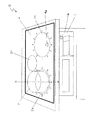
図1は、本発明にかかる誘導加熱調理器Cの外観斜視図であり、図1に示されるように、本発明にかかる誘導加熱調理器Cは、外郭を構成する本体1と、本体1の上部に取り付けられ鍋等の調理容器Pが載置される天板4と、後述する天板4の下方に設けられ高周波磁界を発生させる略円盤状の加熱コイル5(図3参照)とを備えている。
(First embodiment)
FIG. 1 is an external perspective view of an induction heating cooker C according to the present invention. As shown in FIG. 1, the induction heating cooker C according to the present invention includes a
天板4は、光を透過する非磁性体で結晶化セラミック等の絶縁体を材料として板状に形成されている。また、天板4には、その裏面または表面に加熱コイル5上面に対応して対向した円形状の領域が表示されるように印刷され、調理容器Pを載置する範囲が表示された加熱部2a、2b、2cが設けられている。
The top plate 4 is a non-magnetic material that transmits light and is formed into a plate shape using an insulator such as crystallized ceramic as a material. In addition, the top plate 4 is printed so that a circular area facing the upper surface of the
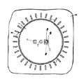
ここで、図1の誘導加熱調理器Cに設けられた天板4における加熱部2a、2bの要部部分平面図である図2を示す。図2に示すように、加熱部2a、2bには、さらに後述する赤外線センサ表示窓4gが形成されており、その平面形状は略長方形となっている。赤外線センサ表示窓4gは、その範囲内(内側)に後述する導光部14(図3参照)の上端の開口部に対向する領域であって調理容器Pから放射され赤外線センサ10が受光する赤外線の入射領域である赤外線入射領域4aと、後述する発光体11から出射された光が視認できる範囲である発光領域4bとが含まれるようにして形成されている。なお、赤外線センサ表示窓4gは、外側から見て内部が見えにくくするための例えば白色、茶色等の半透明の印刷膜(図示せず)を設けても良い。また、赤外線センサ表示窓4g全体を赤外線が透過できるようにしても良い。また、赤外線センサ表示窓4g内の一部においてトップププレート4下面に遮光層膜(図示せず)を設けてもよい。例えば、赤外線入射領域4a及び発光部9(図3参照)から出射された光の発光領域4b以外の赤外線センサ表示窓4gの領域内の光の透過を、遮光層を設けることにより、赤外線センサ8(図3参照)への外乱光の侵入を抑制することができる。
Here, FIG. 2 which is a principal part partial top view of the
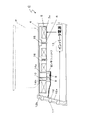
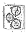
ここで、本第1実施形態にかかる誘導加熱調理器Cの概略断面図、すなわち図1における加熱部2aの中心を通り、本体1前面1aに垂直な直線X−Xにおける断面の概略図を図3に示し、第1実施形態にかかる誘導加熱調理器Cの内部を示す略平面図を図4に示す。 Here, a schematic cross-sectional view of the induction heating cooker C according to the first embodiment, that is, a schematic cross-sectional view along a straight line XX passing through the center of the heating unit 2a in FIG. 4 is a schematic plan view showing the inside of the induction heating cooker C according to the first embodiment shown in FIG.
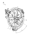
図3に示すように、加熱部2aの下方には、第1の加熱コイルユニット3aが配置されている。第1の加熱コイルユニット3aは、高周波電流を流すことにより高周波磁界を発生させて被加熱物Pを誘導加熱する略円盤状の加熱コイル5及び加熱コイル5を支持するコイル支持板6を有している。加熱部2bの下にも、第1の加熱コイルユニット3aと同様な、加熱コイル5及びコイル支持板6を有する第2の加熱コイルユニット3bが配置されている。また、加熱部2cの下にも、加熱コイルユニット3cが配置されている。なお、第1の加熱コイルユニット3aと第2の加熱コイルユニット3bは、後述するセンサユニットの取付位置が異なるだけで、構成部品等は同様であるので、以下、第1の加熱コイルユニット3aを用いて説明する。
As shown in FIG. 3, the 1st
加熱コイル5は、耐熱樹脂等で形成されたコイル支持板6に載置され、複数の棒状のコイルホルダ(図示せず)が加熱コイル5の外周部でコイル支持板6に螺着されることでコイルホルダの先端部により加熱コイル5の内周部が押さえられて保持されており、コイル支持板6の下方には、加熱コイル5の中心から手前側(調理人側から見て、以下同様)に位置する調理容器P底部の温度を検知するセンサユニット7が設けられている。
The
センサユニット7は、調理容器P底部の温度を検知する赤外線センサ8と、天板4に向かって光を出射する発光部9とを備えている。また、赤外線センサ8と発光部9は、基板(図示せず)上に設置され他の電気部品と電気的に接続している。
The
ここで、第1の加熱コイルユニット3aの下から見た斜視図である図5を示す。
Here, FIG. 5 which is the perspective view seen from the bottom of the 1st
コイル支持板6は、センサユニット7を固定するための第1のセンサユニット取付部6a及び第2のセンサユニット取付部6bが形成されている。また、コイル支持板6において、第1のセンサユニット取付部6aは、加熱コイル5の中心に対して角度α回転した位置に第2のセンサユニット取付部6b配置されている。なお、加熱コイル5の中心に対して第1のセンサユニット取付部6a及び第2のセンサユニット取付部6bの間の角度αは、誘導加熱調理器Cの形状の大きさ、他の誘導加熱調理器との部品の共用化などを考慮して適宜決定される。また、コイル支持板6において、第1のセンサユニット取付部6a及び第2のセンサユニット取付部6bは、加熱コイル5の中心から手前側に位置する調理容器P底部の温度を検知できる位置にセンサユニット7が取り付けられるように配置されている。
The
次に、図4を参照して、第1の加熱コイルユニット3a及び第2の加熱コイルユニット3bのコイル支持板におけるセンサユニット7の配置位置について説明する。第1の加熱コイルユニット3aにおいて、センサユニット7は、コイル支持板6に形成されたセンサユニット取付部6aにネジにより固定されている。また、第2の加熱コイルユニット3bにおいて、センサユニット7は、コイル支持板6に形成されたセンサユニット取付部6bにネジにより固定されている。また、本第1の実施形態にかかる誘導加熱調理器Cにおいて、図4に示すように、第2の加熱コイルユニット3bを第1の加熱コイルユニット3aに対して時計方向に角度αだけ回転させ、第1の加熱コイルユニット3aと第2の加熱コイルユニット3bは、所定の間隔で配置されている。これにより、第1の加熱コイルユニット3a及び第2の加熱コイルユニット3bのいずれにおいて、センサユニット7が加熱コイル5の略中心から誘導加熱調理器Cの前面に垂直方向かつ手前側に配置される。その結果、加熱部2a、2bにおいて、赤外線入射領域4aの近傍で加熱コイル5外縁側において発光させる発光体11の光が、誘導加熱調理器Cの手前側に配置されることになるので、調理人がより容易に発光部分を視認することができさらに使い勝手を良くすることができる。
Next, with reference to FIG. 4, the arrangement position of the
このように本第1実施形態の誘導加熱調理器によれば、コイル支持板6に複数のセンサユニット取付部が形成されているので、加熱コイル5及びコイル支持板6を有する第1及び第2の加熱コイルユニット3a、3bのそれぞれが配置される位置に対応して各1個のセンサユニット7を取り付けることができる。これにより、第1及び第2の加熱コイルユニット3a、3bのそれぞれに対して、赤外線センサ8を備えるセンサユニット7を増加させることなく、調理容器Pの高温部を精度よく測定することができる。さらに、第1及び第2の加熱コイルユニット3a、3bのそれぞれに対応する構成部品を設計することなく、部品の共用化ができるので、組立作業性の向上を図ることができ、組立のコストを抑制することができる。
As described above, according to the induction heating cooker of the first embodiment, since the plurality of sensor unit attachment portions are formed on the
また、本第1実施形態にかかるコイル支持板6には、センサユニット取付部6a、6bの2カ所設けて説明したが、例えば第3のセンサユニット取付部6c、第4のセンサユニット取付部6dと、さらに形成されていてもよい。
The
以上のように構成された誘導加熱調理器Cについて、以下その動作、作用を説明する。
食材を被加熱物Pに入れて本発明にかかる誘導加熱調理器Cで調理するに際し、誘導加熱調理器Cの電源スイッチ(図示せず)を投入すると、発光部9が発光してその出射光が導光体10に導かれて天板4の赤外線入射領域4aの近傍(加熱コイル5の中心より手前側で赤外線入射領域4aに対して加熱コイル5の径方向外側、本実施の形態では、加熱コイル5の中心を通り本体1の前面と直交する線上)の発光領域4bに照射される。したがって、ユーザは赤外線入射領域4aに対して加熱コイル5の径方向外側に設けられた発光領域4bの発光を視認することができ、発光領域4bを塞ぐように被加熱物Pを天板4上に載置すれば赤外線センサ8が被加熱物Pの底面から放射される赤外線を確実に受光することができる。
About the induction heating cooking appliance C comprised as mentioned above, the operation | movement and an effect | action are demonstrated below.
When the food is put into the object to be heated P and cooked by the induction heating cooker C according to the present invention, when the power switch (not shown) of the induction heating cooker C is turned on, the
操作パネル11を操作して加熱開始が指示されると、制御手段12aはインバータ電源13を介して加熱コイル5に高周波電流を供給する。加熱コイル5に高周波電流が供給されると、加熱コイル5は交流磁界を発生し、被加熱物Pは誘導加熱によって温度が上昇する。被加熱物Pの温度が上昇すると、ステファン・ボルツマンの法則に示されるように、被加熱物Pは一般にその絶対温度の4乗に比例した赤外線エネルギーを放射する。被加熱物Pから放射された赤外線は、赤外線入射領域4aと第1の導光部14a内部を通過し赤外線センサ8に到達する。
When the
また、被加熱物Pの温度が高くなると、赤外線エネルギーを受けた赤外線センサ8の出力信号は大きくなり、上述したように、この出力信号は増幅器により増幅されて温度換算手段12bに入力され、温度換算手段12bで赤外線センサ8の出力信号を被加熱物Pの温度に換算する。制御手段12aは、換算された被加熱物Pの温度があらかじめ設定された所定の温度を超えるとインバータ電源13から加熱コイル5に出力される高周波電流の供給を停止しあるいは高周波電流を低減するように調節する。
When the temperature of the article P to be heated increases, the output signal of the
赤外線入射領域4aは加熱コイル5の外縁部の内側で加熱コイル5の中心とは異なる部位に位置するように設けられた、第1の導光部14a上端の開口面に対向するように形成される天板4の部分である。第2の導光部14bで導かれた発光部9の出射光を赤外線入射領域4aより加熱コイル5の径方向外側で発光させ視認できるようにしたので、加熱コイル5の中心部上方より高温となる被加熱物Pの部分が放射する赤外線を、赤外線センサ8に入射させることができ、かつ被加熱物Pの中心を加熱コイル5中心に対して、可能なだけ近づけて発光領域4bを被加熱物Pの底面で覆うことができる。これにより、加熱コイル5と加熱容器Pの磁気結合を大きくしつつ、すなわち加熱効率を高めつつ赤外線入射領域4aの上に被加熱物P底面が位置するようにさせることができる。したがって、加熱効率を高くしながら赤外線センサ8による被加熱物Pの温度制御を確実に行うことが可能となり、被加熱物Pの異常な発熱を抑制し安全性が向上するとともに、高温での調理を効率良く行うことができ、使い勝手が向上する。
The infrared incident region 4a is formed so as to face the opening surface at the upper end of the first
また、天板4は赤外線入射領域4aの少なくとも一部を取り囲む領域を表示する赤外線センサ表示窓4gを備え、発光部9から出射された光は赤外線センサ表示窓4gの近傍で視認できるようにしたので、ユーザは、発光部9の発光領域4bでの発光の意味、発光しない赤外線入射領域4aさらには赤外線センサ8の存在を、赤外線センサ表示窓4g近傍での発光部9の光による発光領域4bと赤外線入射領域4aを関連付けることにより、容易に認識することができる。
The top plate 4 includes an infrared sensor display window 4g for displaying an area surrounding at least a part of the infrared incident area 4a, and the light emitted from the
また、赤外線入射領域4aを加熱コイル5の中心より手前側に位置させるようにしたので、赤外線入射領域4aの近傍で加熱コイル5外縁側において発光させる発光部9の光が、その上方に調理容器Pが位置していない場合に、調理人側から見て調理容器Pの側壁で隠れにくくなり、調理人がより容易に発光部分を視認することができる。
Further, since the infrared incident area 4a is positioned on the front side of the center of the
また、赤外線入射領域4aを加熱コイル5の中心を通り本体前面と直交する線上に位置させるようにしたので、赤外線入射領域4aの近傍で加熱コイル5外縁側において発光させる発光部9の光が、その上方に被加熱物Pが位置していない場合に、ユーザ側から見て被加熱物Pの側壁で最も隠れにくくなり、ユーザが最も容易に発光部分を視認することができさらに使い勝手を良くすることができる。
In addition, since the infrared incident region 4a is positioned on a line that passes through the center of the
また、加熱コイル5の中心に対して赤外線入射領域4aの反対側に天板4の裏面温度を熱伝導で検知する第1の温度検知手段である第1のサーミスタ15を設けると、加熱コイル5中心上部の被加熱物Pの温度より高温部を測定する赤外線センサ8に加え、加熱コイル5中心上部より温度の高くなる被加熱物Pの部分の温度を第1のサーミスタ15で測定することになるので、赤外線センサ8が故障した場合や、被加熱物Pが赤外線入射領域4aを適切に覆っていない場合等、赤外線センサ8で被加熱物Pの温度を検知できない場合でも、第1のサーミスタ15で被加熱物Pの温度を検知できるので、安全性及び使い勝手がさらに向上する。
Further, when the
また、加熱コイル5の略中心に天板4の裏面温度を熱伝導で検知する第2の温度検知手段である第2のサーミスタ16を設けると、被加熱物Pの加熱コイル5中心の上方に位置する底面部分に比べより高温となる被加熱物Pの部分を測定する赤外線センサ8に加え、被加熱物Pの底面温度を加熱コイル5の中心に対する被加熱物Pの中心位置のずれに対して最も安定的に第2のサーミスタ16で測定することになるので、赤外線センサ8に外乱光が入射した場合、赤外線センサ8や温度換算手段12b等の赤外線センサ8による温度測定回路が故障した場合、または被加熱物Pが赤外線入射領域4aを覆っていない場合等、赤外線センサ8で被加熱物Pの温度を検知できない場合でも、第2のサーミスタ16で被加熱物Pの温度を検知できるので、揚げ物調理時における油の温度などの安定温度を精度良く制御することができ、使い勝手がさらに向上する。加熱コイル5の中心に対して赤外線センサ8の反対側に第1のサーミスタ15をさらに設けることにより、外乱光が赤外線センサ8に入射した場合や被加熱物Pの位置ずれが起きた場合の信頼性を高めることができる。
Further, when a second thermistor 16 serving as a second temperature detecting means for detecting the back surface temperature of the top plate 4 by heat conduction is provided at substantially the center of the
(第2実施形態)
なお、本発明は上記実施形態に限定されるものではなく、その他種々の態様で実施できる。例えば、本発明の第2実施形態にかかる誘導加熱調理器Cに構成される第1の加熱コイルユニット23aの下から見た分解斜視図を図6に示す。なお、第1の加熱コイルユニット23a自体の構成は、上記第1実施形態の第1の加熱コイルユニット3aと同じであるので、同じ構成部材には同じ参照符号を付してその説明を省略する。本第2実施形態にかかる誘導加熱調理器Cにおいて、加熱部2a及び2bの下方に、第1の加熱コイルユニット23a及び第2の加熱コイルユニット23bが配置されている。また、第2の加熱コイルユニット23bは、第1の加熱コイルユニット23a自体の構成と同様である。以下、第1の加熱コイルユニット23aを用いて説明する。
(Second Embodiment)
In addition, this invention is not limited to the said embodiment, It can implement with another various aspect. For example, FIG. 6 shows an exploded perspective view of the induction heating cooker C according to the second embodiment of the present invention as viewed from below the first heating coil unit 23a. Since the configuration of the first heating coil unit 23a itself is the same as that of the first
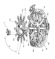
ここで、本第2実施形態にかかる誘導加熱調理器Cにおける第1の加熱コイルユニット23aの下から見た場合の模式分解斜視図である図6を示す。 Here, FIG. 6 is a schematic exploded perspective view when viewed from below the first heating coil unit 23a in the induction heating cooker C according to the second embodiment.
図6に示すように、本第2実施形態にかかる第1の加熱コイルユニット23aは、加熱コイル5(図示せず)、磁性体18、コイル支持板26、導光ユニット27を備えている。
As shown in FIG. 6, the first heating coil unit 23 a according to the second embodiment includes a heating coil 5 (not shown), a
磁性体18は、加熱コイル5からの磁束を加熱コイル5近傍に集中させる。また、コイル支持板6には、放射状に延びる複数の磁性体18が所定の間隔で取り付けられている。
The
コイル支持板26は、上述の第1実施形態と同様に、耐熱樹脂等で形成されている。また、加熱コイル5がコイル支持板6に載置されている。また、コイル支持板26は、後述する導光ユニット27を取り付ける導光ユニット固定部26aが形成されている。また、コイル支持板26には、後述する導光ユニット27に一体的に形成された導光部14が挿入される導光部受け容れ部26が形成されている。
The
導光ユニット27は、第1の導光ユニット取付部27a及び第2の導光ユニット取付部27bが形成されている。また、導光ユニット27において、第1の導光ユニット取付部27aは、加熱コイル5の中心に対して角度α回転した位置に第2の導光ユニット取付部27b配置されている。なお、加熱コイル5の中心に対して第1の導光ユニット取付部27a及び第2の導光ユニット取付部27bの間の角度αは、誘導加熱調理器Cの形状の大きさ、他の誘導加熱調理器との部品の共用化などを考慮して適宜決定される。また、導光ユニット27において、第1のセンサユニット取付部27a及び第2のセンサユニット取付部27bは、加熱コイル5の中心から手前側に位置する調理容器P底部の温度を検知できる位置にセンサユニット7が取り付けられるように配置されている。
The
また、導光ユニット27は、センサユニット取付部26cが形成されており、センサユニット7がセンサユニット取付部26cにビスで固定されている。さらに、導光ユニット27は、導光部14が一体的に形成されている。
Further, the
また、導光ユニット27は、複数の磁性体保持部27dが形成されている。これにより、コイル支持板26に固定されている複数の磁性体18の端部を導光ユニット27に形成された複数の磁性体保持部27dにより保持するので、磁性体18を機械的に保持すると同時に磁性体保持部27dを加熱コイル5に固定することができ、構成が簡素になる。
The
導光ユニット27がコイル支持板26に固定される際、導光ユニット固定部26aが第1の導光ユニット取付部27a又は第2の導光ユニット取付部27bのどちらか一方とビスで固定される。また、第1の導光ユニット取付部27a又は第2の導光ユニット取付部27bのどちらかは、誘導加熱調理器Cにおける第1及び第2の加熱コイルユニット23a、23bの配置位置に対応して決定される。また、導光ユニット27がコイル支持板26に固定される際、導光ユニット27に一体的に形成された導光部14は、導光ユニット固定部26aに固定される第1の導光ユニット取付部27a又は第2の導光ユニット取付部27bのどちらか一方に対応して、コイル支持板26に形成された導光部受け容れ部26のどちらか一方に挿入される。これにより、センサユニット7に備えられた赤外線センサ8に調理容器Pから放射される赤外線を受光し、発光部9から出射された光が赤外線センサ表示窓4gを通して視認することができる。
When the
また、本第2の実施形態にかかる誘導加熱調理器Cにおいて、第1の加熱コイルユニット23aと第2の加熱コイルユニット23bが所定の間隔で配置されることで、本第1実施形態にかかる誘導加熱調理器Cと同様に、第2の加熱コイルユニット23bが第1の加熱コイルユニット23aに対して時計方向に角度αだけ回転させたように配置される。これにより、第1の加熱コイルユニット23a及び第2の加熱コイルユニット23bのいずれにおいて、センサユニット7が加熱コイル5の略中心から誘導加熱調理器Cの前面に垂直方向かつ手前側に配置される。その結果、加熱部2a、2bにおいて、赤外線入射領域4aの近傍で加熱コイル5外縁側において発光させる発光体11の光が、誘導加熱調理器Cの手前側に配置されることになるので、調理人がより容易に発光部分を視認することができさらに使い勝手を良くすることができる。
In addition, in the induction heating cooker C according to the second embodiment, the first heating coil unit 23a and the second heating coil unit 23b are arranged at a predetermined interval, so that the first embodiment is applied. Similarly to the induction heating cooker C, the second heating coil unit 23b is arranged so as to be rotated clockwise by an angle α with respect to the first heating coil unit 23a. Thereby, in any of the 1st heating coil unit 23a and the 2nd heating coil unit 23b,
このように本第2実施形態の誘導加熱調理器によれば、導光ユニット27に複数の導光ユニット取付部が形成されているので、加熱コイル5及びコイル支持板6を有する第1及び第2の加熱コイルユニット23a、23bのそれぞれが配置される位置に対応してセンサユニット7が固定された導光ユニット27をこていすることができる。これにより、第1及び第2の加熱コイルユニット23a、23bのそれぞれに対して、赤外線センサ8を備えるセンサユニット7を増加させることなく、すなわち各1個のセンサユニット7で、調理容器Pの高温部を精度よく測定することができる。さらに、第1及び第2の加熱コイルユニット23a、23bのそれぞれに対応する構成部品を設計することなく、部品の共用化ができるので、組立作業性の向上を図ることができ、組立のコストを抑制することができる。
As described above, according to the induction heating cooker of the second embodiment, since the
また、本第2実施形態の誘導加熱調理器によれば、導光ユニット27にセンサユニット7が固定される部分及び磁性体18が保持される部分の構成が採用されることで、コイル支持板26に要求される機能が単純となるため、コイル支持板26の形状を単純にすることができる。これにより、コイル支持板26の金型構成が簡易になり、金型作製等の製造コストを下げることができるという利点を有している。
Further, according to the induction heating cooker of the second embodiment, the coil support plate is configured by adopting the configuration of the portion where the
上記において、本発明を詳細に説明したが、上記説明はあらゆる意味において例示的なものであり限定的なものではない。本発明の範囲から逸脱することなしに多くの他の改変例及び変形例が可能であることは言うまでもない。 While the present invention has been described in detail above, the above description is in all respects illustrative and not restrictive. Of course, many other modifications and variations are possible without departing from the scope of the invention.
なお、上記様々な実施形態のうちの任意の実施形態を適宜組み合わせることにより、それぞれの有する効果を奏するようにすることができる。 It is to be noted that, by appropriately combining arbitrary embodiments of the various embodiments described above, the effects possessed by them can be produced.
本発明にかかる誘導加熱調理器は、赤外線センサを増加させることなく、かつ、複数の誘導加熱部分を有する誘導加熱調理器を構成する部材を共用化することができる効果を有し、調理容器を誘導加熱するとともに、赤外線センサを用いて調理容器の温度を制御する家庭用又は業務用の誘導加熱調理器等に有用である。 The induction heating cooker according to the present invention has the effect that the members constituting the induction heating cooker having a plurality of induction heating portions can be shared without increasing the number of infrared sensors. In addition to induction heating, the present invention is useful for home or business induction heating cookers that use an infrared sensor to control the temperature of a cooking container.
1 本体、 2 加熱部、 2a 第1の加熱部、 2b 第2の加熱部、
3a 第1の加熱コイルユニット、 3b 第2の加熱コイルユニット、4 天板、
4a 赤外線入射領域、 4b 発光領域、 4g 赤外線センサ表示窓、
5 加熱コイル、 6 コイル支持板、 6a 第1のセンサユニット取付部、
6b 第2のセンサユニット取付部 7 センサユニット、8 受光部、 9 発光部、11 操作パネル、 12 制御基板、 12a 制御手段、 12b 温度換算手段、14 導光部、 15 第1のサーミスタ、 16 第2のサーミスタ、
18 磁性体、 23a 第1の加熱部、 23b 第2の加熱部、
26 コイル支持板、 26a 導光ユニット固定部、 26b 導光部受け容れ部、 27 導光ユニット、 27a 第1の導光ユニット取付部、
27b 第2の導光ユニット取付部、 27c センサユニット取付部、
27d 磁性体保持部、 27 反射抑制手段、 C 誘導加熱調理器、 P 調理容器
1 body, 2 heating section, 2a first heating section, 2b second heating section,
3a 1st heating coil unit, 3b 2nd heating coil unit, 4 top plate,
4a Infrared incident area, 4b Emission area, 4g Infrared sensor display window,
5 heating coil, 6 coil support plate, 6a first sensor unit mounting portion,
6b Second sensor
18 Magnetic body, 23a 1st heating part, 23b 2nd heating part,
26 coil support plate, 26a light guide unit fixing part, 26b light guide part receiving part, 27 light guide unit, 27a first light guide unit mounting part,
27b second light guide unit mounting portion, 27c sensor unit mounting portion,
27d Magnetic body holding part, 27 reflection suppression means, C induction heating cooker, P cooking container
Claims (4)
前記天板に対向して前記天板の下方に設けられ、交流磁界を発生して調理容器を誘導加熱する加熱コイルと前記加熱コイルを支持するコイル支持板を有する第1及び第2の加熱コイルユニットと、
前記加熱コイルの下方に設けられ、調理容器から放射される赤外線を検知する受光部を含むセンサユニットと、
前記受光部の出力に応じて前記加熱コイルに供給する電力を制御する制御手段とを備え、
前記コイル支持板は、前記センサユニットを取り付ける複数のセンサユニット取付部を有し、
前記第1及び第2の加熱コイルユニットのそれぞれに取り付けられる前記センサユニットのそれぞれは、前記コイル支持板における複数の前記センサユニット取付部のうち、互いに異なる前記センサユニット取付部に取り付けられ、
前記誘導加熱調理器本体における前記第2の加熱コイルユニットを前記第1の加熱コイルユニットに対して所定の角度を回転させて、前記第1の加熱コイルユニットと前記第2の加熱コイルユニットとが所定の間隔で配置されることを特徴とする、誘導加熱調理器。 A top plate that is attached to the upper part of the induction heating cooker body constituting the outer shell and on which a plurality of cooking containers are placed;
First and second heating coils, which are provided below the top plate so as to face the top plate, have a heating coil that generates an AC magnetic field and induction-heats the cooking vessel, and a coil support plate that supports the heating coil. Unit,
A sensor unit that is provided below the heating coil and includes a light receiving unit that detects infrared rays emitted from the cooking container;
Control means for controlling the power supplied to the heating coil according to the output of the light receiving unit,
The coil support plate has a plurality of sensor unit mounting portions for mounting the sensor unit,
Each of the sensor units attached to each of the first and second heating coil units is attached to the different sensor unit attachment portions among the plurality of sensor unit attachment portions of the coil support plate,
The second heating coil unit in the induction heating cooker body is rotated by a predetermined angle with respect to the first heating coil unit, and the first heating coil unit and the second heating coil unit are An induction heating cooker, which is arranged at a predetermined interval.
前記コイル支持板は、前記導光ユニットを取り付ける複数の導光ユニット固定部と、前記導光部が挿入される導光部受け容れ部とが形成される構成とすることに代え、
前記導光ユニットは、前記コイル支持板に取り付ける複数の導光ユニット取付部を有し、
前記第1及び第2の加熱コイルユニットのそれぞれの前記コイル支持板に取り付けられる前記導光ユニットのそれぞれは、前記導光ユニットにおける複数の前記導光ユニット取付部のうち、互いに異なる前記導光ユニット取付部に取り付けられる、請求項1に記載の誘導加熱調理器。 A sensor unit mounting portion for mounting the sensor unit, and a light guide portion for guiding infrared rays from the cooking container to the light receiving portion through an infrared incident region through which infrared rays radiated from the cooking vessel formed on the top plate are transmitted. A light guide unit further comprising:
The coil support plate is replaced with a configuration in which a plurality of light guide unit fixing portions to which the light guide unit is attached and a light guide portion receiving portion into which the light guide portion is inserted, are formed.
The light guide unit has a plurality of light guide unit attachment parts attached to the coil support plate,
The light guide units attached to the coil support plates of the first and second heating coil units are different from each other among the plurality of light guide unit attachment portions in the light guide unit. The induction heating cooker according to claim 1 attached to an attaching part.
前記導光ユニットは、複数の前記磁性体の端部を保持する、請求項3に記載の誘導加熱調理器。 A plurality of magnetic bodies provided below the heating coil;
The induction heating cooker according to claim 3, wherein the light guide unit holds end portions of the plurality of magnetic bodies.
Priority Applications (1)
| Application Number | Priority Date | Filing Date | Title |
|---|---|---|---|
| JP2007226076A JP5052262B2 (en) | 2007-08-31 | 2007-08-31 | Induction heating cooker |
Applications Claiming Priority (1)
| Application Number | Priority Date | Filing Date | Title |
|---|---|---|---|
| JP2007226076A JP5052262B2 (en) | 2007-08-31 | 2007-08-31 | Induction heating cooker |
Publications (2)
| Publication Number | Publication Date |
|---|---|
| JP2009059592A true JP2009059592A (en) | 2009-03-19 |
| JP5052262B2 JP5052262B2 (en) | 2012-10-17 |
Family
ID=40555151
Family Applications (1)
| Application Number | Title | Priority Date | Filing Date |
|---|---|---|---|
| JP2007226076A Active JP5052262B2 (en) | 2007-08-31 | 2007-08-31 | Induction heating cooker |
Country Status (1)
| Country | Link |
|---|---|
| JP (1) | JP5052262B2 (en) |
Cited By (1)
| Publication number | Priority date | Publication date | Assignee | Title |
|---|---|---|---|---|
| JP2012009305A (en) * | 2010-06-25 | 2012-01-12 | Mitsubishi Electric Corp | Induction heating cooker |
Citations (8)
| Publication number | Priority date | Publication date | Assignee | Title |
|---|---|---|---|---|
| JP2000348856A (en) * | 1999-06-02 | 2000-12-15 | Matsushita Electric Ind Co Ltd | Induction heating cooker |
| JP2002198164A (en) * | 2000-12-27 | 2002-07-12 | Matsushita Electric Ind Co Ltd | Induction cooker |
| JP2005122964A (en) * | 2003-10-15 | 2005-05-12 | Matsushita Electric Ind Co Ltd | Induction heating cooker |
| JP2007213826A (en) * | 2006-02-07 | 2007-08-23 | Matsushita Electric Ind Co Ltd | Induction heating device |
| WO2008075673A1 (en) * | 2006-12-18 | 2008-06-26 | Panasonic Corporation | Induction heating cooking device |
| JP2008153046A (en) * | 2006-12-18 | 2008-07-03 | Matsushita Electric Ind Co Ltd | Induction cooking device |
| JP2008226573A (en) * | 2007-03-12 | 2008-09-25 | Matsushita Electric Ind Co Ltd | Induction cooker |
| JP2008293764A (en) * | 2007-05-24 | 2008-12-04 | Panasonic Corp | Induction heating cooker |
-
2007
- 2007-08-31 JP JP2007226076A patent/JP5052262B2/en active Active
Patent Citations (8)
| Publication number | Priority date | Publication date | Assignee | Title |
|---|---|---|---|---|
| JP2000348856A (en) * | 1999-06-02 | 2000-12-15 | Matsushita Electric Ind Co Ltd | Induction heating cooker |
| JP2002198164A (en) * | 2000-12-27 | 2002-07-12 | Matsushita Electric Ind Co Ltd | Induction cooker |
| JP2005122964A (en) * | 2003-10-15 | 2005-05-12 | Matsushita Electric Ind Co Ltd | Induction heating cooker |
| JP2007213826A (en) * | 2006-02-07 | 2007-08-23 | Matsushita Electric Ind Co Ltd | Induction heating device |
| WO2008075673A1 (en) * | 2006-12-18 | 2008-06-26 | Panasonic Corporation | Induction heating cooking device |
| JP2008153046A (en) * | 2006-12-18 | 2008-07-03 | Matsushita Electric Ind Co Ltd | Induction cooking device |
| JP2008226573A (en) * | 2007-03-12 | 2008-09-25 | Matsushita Electric Ind Co Ltd | Induction cooker |
| JP2008293764A (en) * | 2007-05-24 | 2008-12-04 | Panasonic Corp | Induction heating cooker |
Cited By (1)
| Publication number | Priority date | Publication date | Assignee | Title |
|---|---|---|---|---|
| JP2012009305A (en) * | 2010-06-25 | 2012-01-12 | Mitsubishi Electric Corp | Induction heating cooker |
Also Published As
| Publication number | Publication date |
|---|---|
| JP5052262B2 (en) | 2012-10-17 |
Similar Documents
| Publication | Publication Date | Title |
|---|---|---|
| EP2173137B1 (en) | Induction cooker | |
| JP4932548B2 (en) | Induction heating cooker | |
| JP4917923B2 (en) | Induction heating cooker | |
| JP4872822B2 (en) | Induction heating cooker | |
| JP4896695B2 (en) | Induction heating cooker | |
| JP5147841B2 (en) | Induction heating cooker | |
| JP5065378B2 (en) | Induction heating cooker | |
| JP2009059593A (en) | Induction-heating cooker | |
| US11622423B2 (en) | Induction cooker and sensor unit | |
| JP4345504B2 (en) | Induction heating cooker | |
| JP5052262B2 (en) | Induction heating cooker | |
| JP4998128B2 (en) | Induction heating cooker and pot for induction heating cooker | |
| JP4794679B1 (en) | Induction heating cooker | |
| JP2009259835A (en) | Induction cooker | |
| JP5301045B2 (en) | Induction heating cooker | |
| EP3344009B1 (en) | Induction heating cooker | |
| JP7138457B2 (en) | induction cooker | |
| JP7229022B2 (en) | induction cooker | |
| JP4300964B2 (en) | Induction heating cooker | |
| JP2009259836A (en) | Induction cooker | |
| JP2012074343A (en) | Induction heating cooker | |
| JP2008258181A (en) | Induction heating cooker |
Legal Events
| Date | Code | Title | Description |
|---|---|---|---|
| A621 | Written request for application examination |
Free format text: JAPANESE INTERMEDIATE CODE: A621 Effective date: 20091028 |
|
| A131 | Notification of reasons for refusal |
Free format text: JAPANESE INTERMEDIATE CODE: A131 Effective date: 20120214 |
|
| A521 | Written amendment |
Free format text: JAPANESE INTERMEDIATE CODE: A523 Effective date: 20120416 |
|
| TRDD | Decision of grant or rejection written | ||
| A01 | Written decision to grant a patent or to grant a registration (utility model) |
Free format text: JAPANESE INTERMEDIATE CODE: A01 Effective date: 20120710 |
|
| A01 | Written decision to grant a patent or to grant a registration (utility model) |
Free format text: JAPANESE INTERMEDIATE CODE: A01 |
|
| A61 | First payment of annual fees (during grant procedure) |
Free format text: JAPANESE INTERMEDIATE CODE: A61 Effective date: 20120724 |
|
| R150 | Certificate of patent or registration of utility model |
Ref document number: 5052262 Country of ref document: JP Free format text: JAPANESE INTERMEDIATE CODE: R150 Free format text: JAPANESE INTERMEDIATE CODE: R150 |
|
| FPAY | Renewal fee payment (event date is renewal date of database) |
Free format text: PAYMENT UNTIL: 20150803 Year of fee payment: 3 |