JP2009059333A - Method for adjusting inertia sensing range and sensitivity and inertia detection interactive apparatus and system - Google Patents
Method for adjusting inertia sensing range and sensitivity and inertia detection interactive apparatus and system Download PDFInfo
- Publication number
- JP2009059333A JP2009059333A JP2007262133A JP2007262133A JP2009059333A JP 2009059333 A JP2009059333 A JP 2009059333A JP 2007262133 A JP2007262133 A JP 2007262133A JP 2007262133 A JP2007262133 A JP 2007262133A JP 2009059333 A JP2009059333 A JP 2009059333A
- Authority
- JP
- Japan
- Prior art keywords
- detection
- inertial
- signal
- inertia
- interactive
- Prior art date
- Legal status (The legal status is an assumption and is not a legal conclusion. Google has not performed a legal analysis and makes no representation as to the accuracy of the status listed.)
- Pending
Links
Images


Classifications
-
- A63F13/10—
-
- A—HUMAN NECESSITIES
- A63—SPORTS; GAMES; AMUSEMENTS
- A63F—CARD, BOARD, OR ROULETTE GAMES; INDOOR GAMES USING SMALL MOVING PLAYING BODIES; VIDEO GAMES; GAMES NOT OTHERWISE PROVIDED FOR
- A63F13/00—Video games, i.e. games using an electronically generated display having two or more dimensions
- A63F13/20—Input arrangements for video game devices
- A63F13/22—Setup operations, e.g. calibration, key configuration or button assignment
-
- A—HUMAN NECESSITIES
- A63—SPORTS; GAMES; AMUSEMENTS
- A63F—CARD, BOARD, OR ROULETTE GAMES; INDOOR GAMES USING SMALL MOVING PLAYING BODIES; VIDEO GAMES; GAMES NOT OTHERWISE PROVIDED FOR
- A63F13/00—Video games, i.e. games using an electronically generated display having two or more dimensions
- A63F13/20—Input arrangements for video game devices
- A63F13/21—Input arrangements for video game devices characterised by their sensors, purposes or types
- A63F13/211—Input arrangements for video game devices characterised by their sensors, purposes or types using inertial sensors, e.g. accelerometers or gyroscopes
-
- A—HUMAN NECESSITIES
- A63—SPORTS; GAMES; AMUSEMENTS
- A63F—CARD, BOARD, OR ROULETTE GAMES; INDOOR GAMES USING SMALL MOVING PLAYING BODIES; VIDEO GAMES; GAMES NOT OTHERWISE PROVIDED FOR
- A63F13/00—Video games, i.e. games using an electronically generated display having two or more dimensions
- A63F13/45—Controlling the progress of the video game
-
- G—PHYSICS
- G06—COMPUTING; CALCULATING OR COUNTING
- G06F—ELECTRIC DIGITAL DATA PROCESSING
- G06F3/00—Input arrangements for transferring data to be processed into a form capable of being handled by the computer; Output arrangements for transferring data from processing unit to output unit, e.g. interface arrangements
- G06F3/01—Input arrangements or combined input and output arrangements for interaction between user and computer
- G06F3/03—Arrangements for converting the position or the displacement of a member into a coded form
- G06F3/033—Pointing devices displaced or positioned by the user, e.g. mice, trackballs, pens or joysticks; Accessories therefor
- G06F3/0346—Pointing devices displaced or positioned by the user, e.g. mice, trackballs, pens or joysticks; Accessories therefor with detection of the device orientation or free movement in a 3D space, e.g. 3D mice, 6-DOF [six degrees of freedom] pointers using gyroscopes, accelerometers or tilt-sensors
-
- A—HUMAN NECESSITIES
- A63—SPORTS; GAMES; AMUSEMENTS
- A63F—CARD, BOARD, OR ROULETTE GAMES; INDOOR GAMES USING SMALL MOVING PLAYING BODIES; VIDEO GAMES; GAMES NOT OTHERWISE PROVIDED FOR
- A63F2300/00—Features of games using an electronically generated display having two or more dimensions, e.g. on a television screen, showing representations related to the game
- A63F2300/10—Features of games using an electronically generated display having two or more dimensions, e.g. on a television screen, showing representations related to the game characterized by input arrangements for converting player-generated signals into game device control signals
- A63F2300/1018—Calibration; Key and button assignment
-
- A—HUMAN NECESSITIES
- A63—SPORTS; GAMES; AMUSEMENTS
- A63F—CARD, BOARD, OR ROULETTE GAMES; INDOOR GAMES USING SMALL MOVING PLAYING BODIES; VIDEO GAMES; GAMES NOT OTHERWISE PROVIDED FOR
- A63F2300/00—Features of games using an electronically generated display having two or more dimensions, e.g. on a television screen, showing representations related to the game
- A63F2300/10—Features of games using an electronically generated display having two or more dimensions, e.g. on a television screen, showing representations related to the game characterized by input arrangements for converting player-generated signals into game device control signals
- A63F2300/105—Features of games using an electronically generated display having two or more dimensions, e.g. on a television screen, showing representations related to the game characterized by input arrangements for converting player-generated signals into game device control signals using inertial sensors, e.g. accelerometers, gyroscopes
Abstract
Description
本発明は、動的な調整方法およびインタラクティブシステムに関し、特に、慣性検出システムにおいて、使用者の必要に応じて検出パラメータの検出範囲および感度を動的に調整し、使用者とアプリケーションプログラム端との間で好適なインタラクションを行なうことができる慣性検出範囲および感度を調整する方法および慣性検出インタラクティブ装置およびシステムに関する。 The present invention relates to a dynamic adjustment method and an interactive system. In particular, in an inertia detection system, the detection range and sensitivity of a detection parameter are dynamically adjusted according to a user's need, and a user and an application program end The present invention relates to a method for adjusting an inertia detection range and sensitivity, and an inertia detection interactive apparatus and system capable of performing suitable interaction between them.
マルチメディアゲームの発展は長く続いてきたが、近年は半導体産業の急速な発展が電子産業の成長および進歩を促し、関連するインタラクティブプラットフォームの演算処理能力も大幅に向上した。それによって、マルチメディアゲームは音声、画像または動画の何れの領域においても大きな発展を達成し、使用者はマルチメディアゲームで遊ぶときに幻想の世界に浸ることができ、高い娯楽性を享受することができるようになった。 Although the development of multimedia games has continued for a long time, in recent years, the rapid development of the semiconductor industry has spurred the growth and advancement of the electronics industry, and the computing power of related interactive platforms has also been greatly improved. As a result, multimedia games have made great progress in any area of voice, image or video, and users can be immersed in the world of fantasy when playing multimedia games and enjoy high entertainment. Can now.
マルチメディアゲームの映像音声は、ゲームの娯楽性に大きな影響を与えるが、多くのマルチメディアゲームの使用者とゲームとの間のコミュニケーションはキーボード、マウスまたはジョイスティックなどの従来技術による入力インターフェースによって行なわれ、いずれの種類のマルチメディアゲームでも、使用者は手で従来技術による入力インターフェースを操作してゲームとインタラクションを行なうだけなのでゲームの娯楽性が低下していた。 Although the video and audio of multimedia games have a great impact on the entertainment of the game, communication between the users of many multimedia games and the game is performed by a conventional input interface such as a keyboard, mouse or joystick. In any kind of multimedia game, since the user simply interacts with the game by operating the input interface according to the prior art by hand, the entertainment of the game has been reduced.
特許文献1または特許文献2において開示されているゲームの制御装置およびゲームシステムは、画期的な操作制御方式であり、使用者の四肢動作によってゲームの進行を制御するものである。この種のゲームシステムの代表としては、任天堂(株)の次世代ゲーム機Wii(登録商標)が存在し、複数のボタンを押圧して操作する代わりに、四肢の指向または揺動による直感的な動作を検出して操作を行なうことによりゲームコントロールに新たな風潮をもたらした。 The game control device and the game system disclosed in Patent Document 1 or Patent Document 2 are epoch-making operation control systems, and control the progress of the game by the user's limb movements. As a representative of this type of game system, there is a next-generation game machine Wii (registered trademark) of Nintendo Co., Ltd. Intuitive by directing or swinging the limbs instead of pressing and operating a plurality of buttons. By detecting movements and performing operations, it brought a new trend to game control.
上述の技術で、使用者が操作インターフェースを通じてゲームとインタラクションを行なう過程において、操作インターフェースが使用者の動作を検出して生成する検出パラメータは、一般的にゲームとの間で一対一のインタラクティブな関係にある。つまり、使用者の出力が小さいとき生成される検出パラメータは小さくなるので、インタラクティブゲームは、小さい反応かそれに対応する反応を示し、反対に、使用者からの出力が大きいとき、インタラクティブゲームは、大きい反応かそれに対応する反応を示し、ゲームまたはアプリケーションプログラム端では使用者の状況に応じた動的な調整を行なうことができない。 In the above-described technique, the detection parameters generated by the operation interface detecting the user's movement in the process of the user interacting with the game through the operation interface generally have a one-to-one interactive relationship with the game. It is in. That is, the detection parameters generated when the user's output is small are small, so the interactive game shows a small response or a corresponding response, and conversely, when the user's output is large, the interactive game is large A reaction or a corresponding reaction is shown, and the game or application program end cannot dynamically adjust according to the situation of the user.
例えば、ゲームまたはアプリケーションプログラム端がフラフープゲームで、ゲーム進行中に慣性センサが+2gから−2gまでを検出したときインタラクションが行われるように設定されているとする。この設定は、一部の使用者にとっては問題がないが、子供または四肢に異常がある人の場合、+1gから−1gまでしか生成できない場合があるので、これらの一部の人は+2gから+1gまでおよび−1gから−2gまでの動作に応じたインタラクティブな娯楽性を享受することができない。 For example, it is assumed that the game or application program end is a hula hoop game, and that the interaction is set to be performed when the inertial sensor detects from +2 g to −2 g while the game is in progress. This setting is not a problem for some users, but for children or people with abnormal limbs, it may only generate from + 1g to -1g, so some of these people will have + 2g to + 1g And interactive entertainment according to the operations from -1g to -2g cannot be enjoyed.
一般の慣性センサには複数の検出範囲が用意され、使用者は検出範囲および感度を設定できる。しかし、設定後はその検出範囲が固定され、必要に応じて調整をすることができない。 A general inertial sensor has a plurality of detection ranges, and the user can set the detection range and sensitivity. However, after the setting, the detection range is fixed and cannot be adjusted as necessary.
従って、使用者が検出範囲および感度を動的に調整でき、様々な使用者にアプリケーションプログラムとインタラクションを行なう効果を提供できる慣性検出範囲および感度を調整する方法および慣性検出インタラクティブシステムが必要とされていた。
本発明の第1の目的は、切換選択が可能であって、使用者が必要に応じて慣性センサの検出範囲および感度を動的に調整できる慣性検出範囲および感度を調整する方法および慣性検出インタラクティブ装置およびシステムを提供することにある。
本発明の第2の目的は、切換選択が可能であって、使用者が必要に応じて慣性検出装置の出力信号の強弱比率を動的に調整できる慣性検出範囲および感度を調整する方法および慣性検出インタラクティブ装置およびシステムを提供することにある。
本発明の第3の目的は、切換選択が可能であって、使用者が必要に応じて慣性検出装置が発信する調信号を制御し、受信側であるアプリケーションプログラム端の判断閾値の大きさを動的に調整できる慣性検出範囲および感度を調整する方法および慣性検出インタラクティブ装置およびシステムを提供することにある。
本発明の第4の目的は、アプリケーションプログラム端が発信する切換信号によって慣性検出装置の出力信号の大きさまたは内部の慣性センサの検出範囲を動的に調整できる慣性検出範囲および感度を調整する方法および慣性検出インタラクティブ装置およびシステムを提供することにある。
A first object of the present invention is a method and an inertia detection interactive method for adjusting an inertia detection range and sensitivity, which can be switched and allows a user to dynamically adjust a detection range and sensitivity of an inertial sensor as needed. It is to provide an apparatus and system.
A second object of the present invention is a method and inertia for adjusting an inertia detection range and sensitivity that can be switched and allows the user to dynamically adjust the strength ratio of the output signal of the inertia detection device as required. It is to provide a detection interactive device and system.
The third object of the present invention is to allow switching selection, and the user controls the adjustment signal transmitted by the inertia detection device as necessary, and sets the size of the judgment threshold at the application program end on the receiving side. It is an object to provide a method and an inertial detection interactive apparatus and system for adjusting the inertial detection range and sensitivity that can be dynamically adjusted.
A fourth object of the present invention is a method for adjusting an inertia detection range and sensitivity capable of dynamically adjusting the magnitude of an output signal of an inertia detection device or a detection range of an internal inertia sensor by a switching signal transmitted from an application program end. And providing an inertial detection interactive apparatus and system.
本発明は、慣性検出範囲および感度を調整する方法を提供するものであり、切換信号があるかどうかを判断するステップと、切換信号を受信した場合、可動物体の動作の検出範囲を変更するステップと、可動物体の動作を検出して少なくとも一つの検出パラメータを生成するステップと、少なくとも一つの検出パラメータを処理して対応する出力信号を形成するステップと、を含む。 The present invention provides a method for adjusting an inertia detection range and sensitivity, and includes a step of determining whether or not there is a switching signal, and a step of changing the detection range of the movement of a movable object when the switching signal is received. And detecting at least one detection parameter to generate a corresponding output signal by detecting the movement of the movable object and generating at least one detection parameter.
本発明は、慣性検出範囲および感度を調整する方法を提供するものであり、可動物体の動作を検出して少なくとも一つの検出パラメータを生成するステップと、切換信号があるかどうかを判断するステップと、切換信号を受信した場合、比率に基づいて少なくとも一つの検出パラメータの処理によって生成された出力信号の大きさを調整するステップと、を含む。 The present invention provides a method for adjusting an inertia detection range and sensitivity, detecting a motion of a movable object to generate at least one detection parameter, and determining whether there is a switching signal. Adjusting the magnitude of the output signal generated by processing at least one detection parameter based on the ratio when receiving the switching signal.
本発明は、慣性検出範囲および感度を調整する方法を提供するものであり、可動物体の動作を検出して少なくとも一つの検出パラメータを生成するステップと、少なくとも一つの検出パラメータを処理して対応する出力信号を形成するステップと、切換信号があるかどうかを判断するステップと、切換信号を受信した場合、調整信号を発信するステップと、調整信号を受信し、調整信号に基づいて出力信号と判断閾値との関係の比較に使用される判断閾値の調整を行ない、対応結果を生成するステップと、を含む。 The present invention provides a method for adjusting the inertia detection range and sensitivity, and detects at least one detection parameter by detecting the motion of a movable object, and processes and responds to at least one detection parameter. A step of forming an output signal; a step of determining whether there is a switching signal; a step of transmitting an adjustment signal when receiving the switching signal; a step of receiving the adjustment signal; and determining that the output signal is based on the adjustment signal Adjusting a determination threshold value used for comparison of the relationship with the threshold value, and generating a correspondence result.
本発明は、慣性検出インタラクティブシステムを提供するものであり、インタラクティブプラットフォームと、インタラクティブプラットフォームと相互にコミュニケーションを行なう慣性検出装置と、を備え、慣性検出装置は、少なくとも一つの慣性センサを備え、それによって可動物体の動作を検出し、少なくとも一つの検出パラメータを生成する慣性検出モジュールと、第1の切換信号を生成する切換ユニットと、慣性検出モジュールおよび切換ユニットと接続され、少なくとも一つの検出パラメータを処理して出力信号を生成し、第1の切換信号に基づいて慣性検出範囲および感度を調整するマイクロコントローラと、を備える。 The present invention provides an inertial detection interactive system, and includes an interactive platform and an inertial detection device that communicates with the interactive platform. The inertial detection device includes at least one inertial sensor, thereby Connected to the inertia detection module that detects the motion of the movable object and generates at least one detection parameter, the switching unit that generates the first switching signal, the inertia detection module and the switching unit, and processes at least one detection parameter And a microcontroller that adjusts the inertia detection range and sensitivity based on the first switching signal.
本発明は、慣性検出インタラクティブ装置を提供するものであり、運動モジュールと、運動モジュールと相互にコミュニケーションを行なう慣性検出装置とを備え、慣性検出装置は、少なくとも一つの慣性センサを備え、それによって可動物体の動作を検出し、少なくとも一つの検出パラメータを生成する慣性検出モジュールと、第1の切換信号を生成する切換ユニットと、慣性検出モジュールおよび切換ユニットと接続され、少なくとも一つの検出パラメータを処理して出力信号を生成し、第1の切換信号に基づいて慣性検出範囲および感度を調整するマイクロコントローラと、を備える。 The present invention provides an inertial detection interactive device, which includes a motion module and an inertial detection device that communicates with the motion module. The inertial detection device includes at least one inertial sensor and is movable thereby. Connected to the inertia detection module that detects the motion of the object and generates at least one detection parameter, the switching unit that generates the first switching signal, the inertia detection module and the switching unit, and processes at least one detection parameter And a microcontroller that adjusts the inertia detection range and sensitivity based on the first switching signal.
切換信号を受信したとき、慣性センサの検出範囲を調整するか、或いはアプリケーション端の閾値を直接変更することによって慣性検出範囲および感度を動的に調整することができ、如何なる年齢層の使用者でも本発明のメカニズムによって好適なインタラクションを行なうことができる。 When the switching signal is received, the inertial detection range and sensitivity can be adjusted dynamically by adjusting the detection range of the inertial sensor or by directly changing the threshold value at the application end. A preferred interaction can be performed by the mechanism of the present invention.
本発明の目的および機能を明確にするために本発明の装置の関連する詳細部分および基本理念を下記に説明する。 In order to clarify the purpose and function of the present invention, the relevant details and basic principles of the apparatus of the present invention are described below.
図1は、本発明の慣性検出インタラクティブシステムの実施例を示す模式図である。慣性検出インタラクティブシステム2は、インタラクティブプラットフォーム20および少なくとも一つの慣性検出装置21(図中では一つであるが、実際は複数でもよい)を備える。インタラクティブプラットフォーム20は、マルチメディアインタラクティブ装置(例えばマルチメディアゲーム機)、コンピュータまたは家電品である。本実施例ではインタラクティブプラットフォーム20は、マルチメディアゲーム機であり、マルチメディア本体200およびマルチメディア表示ユニット201を備える。慣性検出装置21は、マルチメディアプラットフォーム20とお互いにコミュニケーションを行ない、使用者8とインタラクティブプラットフォーム20との間のインタラクティブな操作インターフェースとなる。
FIG. 1 is a schematic diagram showing an embodiment of the inertial detection interactive system of the present invention. The inertial detection interactive system 2 includes an
図2は、本発明の慣性検出装置の実施例を示すブロック図である。慣性検出装置21は、慣性検出モジュール210、切換ユニット211、送受信モジュール213およびマイクロコントローラ212を備える。慣性検出モジュール210は、少なくとも一つの慣性センサを備え、使用者(または可動物体の可動部位)の空間または平面上での動作を検出し、少なくとも一つの角速度または加速度などの検出パラメータを生成する。慣性センサは、加速度計、ジャイロスコープまたはそれらを組み合わせたものからなる。また、各慣性センサは、±2g(gは重力加速度)/±1g/±0.5gなど切換選択される少なくとも一つの検出範囲を有する。
FIG. 2 is a block diagram showing an embodiment of the inertial detection device of the present invention. The
切換ユニット211は、第1の切換信号を生成する。切換ユニットは、更に切換部材と電気的に接続される。切換部材は、使用者と切換ユニット211とのコミュニケーションインターフェースである。切換部材は、ボタン、スイッチ、ホイールまたはタッチコントロールパネルからなる。送受信モジュール(ユニット)213は、インタラクティブプラットフォーム20とコミュニケーションを行い、インタラクティブプラットフォーム20が送信する信号を受信し、またインタラクティブプラットフォーム20に信号を伝送する。送受信モジュール213は、有線通信または無線通信を選択することができる。有線通信は、RS232、USBまたはイーサネット(登録商標)を選択できる。無線通信は、ブルートゥース、無線周波数通信またはGSMを選択できる。本実施例において、送受信モジュール213は、無線方式によってインタラクティブプラットフォーム20とコミュニケーションを行なう。
The
インタラクティブプラットフォーム20は、第2の切換信号を慣性検出装置21に送信する。マイクロコントローラ212は、慣性検出モジュール210、切換ユニット211および送受信モジュール213と接続される。マイクロコントローラ212は少なくとも一つの検出パラメータを処理して出力信号を生成し、第1の切換信号または第2の切換信号に基づいて慣性検出範囲および感度を調整することができる。また、マイクロコントローラ212は、第1の切換信号に基づいて調整信号を生成し、インタラクティブプラットフォーム20のマルチメディア本体200に伝送する。インタラクティブプラットフォーム20のマルチメディア本体200が調整信号を受信したとき、調整信号に基づいて閾値の大きさを調整する。
The
図3は、本発明の慣性検出範囲および感度を調整する方法の第1の実施例を示すフロー図である。本実施例においては(図1、2も参照)、慣性検出モジュール210の慣性センサは、複数の検出範囲に切り換えることができる。先ずステップ30を行ない、マイクロコントローラ212が切換ユニット211から発信された切換信号を受信したかどうかを判断する。マイクロコントローラ212が切換信号があると判断したとき、ステップ31を行ない、マイクロコンピュータ212が慣性センサの検出範囲および感度を変更する制御コードを読み取る。続いてステップ32を行ない、マイクロコントローラ212が制御コードに基づいて慣性センサの検出範囲および感度を選択する。その後、ステップ33を行ない、使用者8とインタラクティブプラットフォーム20はインタラクションを行なう。反対に、マイクロコントローラ212が切換信号を読み取らなかった場合、ステップ34を行ない、マイクロコントローラ212が予め設けられた慣性センサの検出範囲および感度を制御する制御コードを読み取り、その後ステップ32以降のステップを行なう。
FIG. 3 is a flowchart showing a first embodiment of the method for adjusting the inertia detection range and sensitivity of the present invention. In the present embodiment (see also FIGS. 1 and 2), the inertial sensor of the
図5、6は出力される信号強度および時間の関係を示す図である。図5はステップ34の慣性センサの検出範囲が変更されない場合の出力信号強度とインタラクティブ装置上に設定された判断閾値との関係を示す。直線90はインタラクティブ装置のアプリケーションプログラム端(ゲームソフトまたはマルチメディアソフトなど)に設定された判断閾値である。曲線91は検出範囲が変更されないとき慣性検出装置が発信する出力信号の曲線である。図5から分かるように、出力信号曲線は、アプリケーションプログラム端の判断閾値を超えていないので使用者がどのように操作しても判断閾値を超えることがなく、従って、インタラクティブ装置は使用者とインタラクションを行なうことができない。
5 and 6 are diagrams showing the relationship between the output signal strength and time. FIG. 5 shows the relationship between the output signal intensity and the judgment threshold set on the interactive device when the detection range of the inertial sensor in
図6の曲線92は、検出範囲を変更後の出力信号強度を示す。使用者がステップ31から33を行なうとき、慣性センサの検出範囲はすでに変更されているので、出力信号強度全体が増強され、判断閾値は変更されていないが慣性センサの検出範囲および感度が変更されているので相対的に出力信号強度全体も強化され、それによってインタラクティブ装置が出力信号を検出するとき演算を行なうことができ、使用者とインタラクションを行なう。
A
なぜ使用者が検出範囲を変更したとき、出力信号の強度が変更されるのかを例を挙げて説明する。例えば、慣性センサの予め設定された検出範囲が±2g間の場合、使用者の動作によって生成される加速度が±2g間であれば、慣性検出モジュールは加速度を検出して検出パラメータを生成することができる。慣性センサが±2g間の解析度は、特定のビット数に分割され、例えば2の10乗(これだけに制限されない)の場合、慣性センサは±2g間を1024に分割するので、検出した加速度が2gのとき、出力値は最大の1024となり、1gのときは比率に基づいて256が出力される。しかし、慣性センサの検出範囲が±1gに変更されたとき、上述の説明に基づいて、使用者が1gの加速度を生成すれば最大値1024の読取値を得ることができる。 The reason why the intensity of the output signal is changed when the user changes the detection range will be described with an example. For example, if the preset detection range of the inertial sensor is between ± 2 g, and if the acceleration generated by the user's movement is between ± 2 g, the inertia detection module detects the acceleration and generates a detection parameter Can do. The resolution of the inertial sensor between ± 2 g is divided into a specific number of bits. For example, in the case of 2 to the 10th power (not limited to this), the inertial sensor divides between ± 2 g into 1024. When the value is 2 g, the maximum output value is 1024. When the value is 1 g, 256 is output based on the ratio. However, when the detection range of the inertial sensor is changed to ± 1 g, the reading value of the maximum value 1024 can be obtained if the user generates 1 g of acceleration based on the above description.
図4は、本発明の慣性検出インタラクティブシステムのインタラクション工程を示すフロー図である(図1、2も参照)。先ずステップ330を行ない、慣性検出モジュール210が使用者8の四肢動作を検出して少なくとも一つの検出パラメータを生成する。次に、ステップ331を行ない、マイクロコントローラ212が少なくとも一つの検出パラメータを受信する。その後ステップ332を行ない、マイクロコンピュータ212が少なくとも一つの検出パラメータを処理して出力信号を生成する。最後にステップ333を行ない、送受信モジュール213が出力信号をインタラクティブプラットフォーム20のマルチメディア本体200に伝送し、インタラクティブプラットフォーム20と使用者8との間でインタラクションを行なう。
FIG. 4 is a flowchart showing the interaction process of the inertial detection interactive system of the present invention (see also FIGS. 1 and 2). First,
図7は、本発明の慣性検出範囲および感度を調整する方法の第2の実施例を示すフロー図である(図1、2も参照)。本実施例においては、慣性検出範囲および感度を変更する方式は、慣性検出装置およびインタラクティブ装置の判断閾値によって達成される。その方法4は、先ずステップ40を行ない、マイクロコントローラ212が切換ユニット211からの切換信号を受信したかどうかを判断し、切換信号を検出しなかった場合、ステップ46に戻る。マイクロコントローラ212が切換信号があると判断した場合、ステップ41を行ない、慣性検出範囲および感度の調整方式を判断する。慣性検出装置内の慣性センサの検出範囲を切換える場合、ステップ42からステップ44までを行なう。ステップの詳細は、図3のステップ31からステップ33までと同一であるのでここでは説明は行なわない。反対に、ステップ41においてインタラクティブプラットフォーム20側を切換える場合、ステップ45を行ない、マイクロコントローラ212が送受信モジュール213を通じて調整信号を発信し、インタラクティブプラットフォーム20のマルチメディア本体200が調整信号を受信したとき、アプリケーションプログラム端が制御されて判断閾値が調整される。
FIG. 7 is a flowchart showing a second embodiment of the method for adjusting the inertia detection range and sensitivity of the present invention (see also FIGS. 1 and 2). In the present embodiment, the method of changing the inertia detection range and the sensitivity is achieved by the determination threshold value of the inertia detection device and the interactive device. The
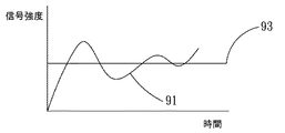
図8、9は、出力される信号強度および時間の関係を示す図である。図8は、ステップ46の慣性センサの検出範囲が変更されない場合の出力信号強度とインタラクティブ装置上に設定された判断閾値との関係を示す。その詳細は、前述の図5の説明で述べているのでここでは説明は行わない。図9の曲線93は、判断閾値を変更した曲線を表す。使用者がステップ44を行なうとき、慣性センサの検出範囲は変更されていないが、アプリケーションプログラム端の判断閾値が変更されているので、相対的に出力信号強度全体も増強され、それによってインタラクティブ装置が出力信号を検出するとき演算を行なうことができ、使用者とインタラクションを行なう。
8 and 9 are diagrams showing the relationship between the output signal strength and the time. FIG. 8 shows the relationship between the output signal intensity and the determination threshold set on the interactive device when the detection range of the inertial sensor in step 46 is not changed. The details are described in the description of FIG. 5 described above, and therefore will not be described here. A
図10は、本発明の慣性検出範囲および感度を調整する方法の第3の実施例を示すフロー図である(図1、2も参照)。本実施例の特徴は、慣性検出モジュール210内の慣性センサが単一の検出範囲を有することにある。その方法は、先ずステップ50を行ない、慣性検出モジュール210が使用者の四肢動作を検出して少なくとも一つの検出パラメータを生成する。次に、ステップ51を行ない、マイクロコントローラ212が少なくとも一つの検出パラメータを受信する。その後、ステップ52を行ない、マイクロコントローラが少なくとも一つの検出パラメータを処理して出力信号を生成する。次にステップ53を行ない、マイクロコントローラ212が切換ユニット211から発信された切換信号を受信したかどうかを判断する。マイクロコントローラ212が切換信号があると判断したとき、ステップ54を行ない、比率に基づいて少なくとも一つの検出パラメータによって生成された出力信号の大きさを調整する。その後、ステップ55を行ない、インタラクティブプラットフォーム20が出力信号に基づいて使用者8とインタラクションを行なう。本実施例において、慣性検出モジュール210内の慣性センサは一つの検出範囲を有するので本実施例の方法は出力信号において比率の拡大または縮小処理を行い、検出範囲は変更できないが、マイクロコントローラの演算処理によって出力信号の大きさを変更することができる。出力信号の比率調整前後の関係は図5、6を参考にすることができる。
FIG. 10 is a flowchart showing a third embodiment of the method for adjusting the inertia detection range and sensitivity of the present invention (see also FIGS. 1 and 2). The feature of this embodiment is that the inertial sensor in the
図11は、本発明の慣性検出範囲および感度を調整する方法の第4の実施例を示すフロー図である(図1、2も参照)。本実施例は単一の検出範囲を有する慣性センサとインタラクティブ装置側の判断閾値の変更とを組み合わせたものである。この方法のステップ60からステップ62までは図10のステップ50から52までと同一であるのでここでは説明を行わない。ステップ63においてマイクロコントローラ212が切換信号があると判断したとき、ステップ64を行ない、慣性検出装置21側またはインタラクティブプラットフォーム20側で感度を変更するかどうかを判断する。慣性検出装置21側で感度を変更する場合、ステップ65およびステップ66を行なう。ステップ65およびステップ66は図10のステップ54および55と同一であるのでここでは説明を行わない。インタラクティブプラットフォーム20側で判断閾値を変更する場合、ステップ67を行ない、マイクロコントローラ212が送受信モジュール213を通じて調整信号を発信し、インタラクティブプラットフォーム20のマルチメディア本体200が調整信号を受信したとき、アプリケーションプログラムが制御されて判断閾値が調整される。
FIG. 11 is a flowchart showing a fourth embodiment of the method for adjusting the inertia detection range and sensitivity of the present invention (see also FIGS. 1 and 2). In this embodiment, an inertial sensor having a single detection range is combined with a change of a determination threshold value on the interactive apparatus side. Steps 60 to 62 of this method are the same as steps 50 to 52 in FIG. 10, and will not be described here. When the
前述の方式(図3、7、10、11)における切換信号は、慣性検出装置側の切換ユニットから発信される。その他、切換信号は慣性検出装置からではなく、インタラクティブ装置側から発信することもできる。しかし、慣性検出装置から発信されようが、インタラクティブ装置から発信されようが、マイクロコントローラが切換信号を受信したとき、判断を行ない、慣性検出範囲および感度を変更する。 The switching signal in the above-described method (FIGS. 3, 7, 10, 11) is transmitted from the switching unit on the inertial detection device side. In addition, the switching signal can be transmitted not from the inertia detection device but from the interactive device side. However, whether it originates from the inertia detection device or from the interactive device, when the microcontroller receives the switching signal, it makes a decision and changes the inertia detection range and sensitivity.
図1および図2の実施例は、マルチメディアのインタラクティブシステムであり、このような実施形態以外に、本発明の方法は、歩数計またはフラフープ(登録商標)のカウンタなどの一般の単純な慣性検出インタラクティブ運動装置に応用することができ、また、これらに制限されない。図12に示すように、本装置7は、切換ユニット70、マイクロコントローラ71、慣性検出モジュール72および運動モジュールを備える。切換ユニット70、マイクロコントローラ71および慣性検出モジュール72は図2の符号210、211および212に示す機能および構造と同一であるのでここでは説明を行わない。運動モジュール73の機能は図1のインタラクティブプラットフォーム20に類似し、例えば、歩数計またはフラフープのカウンタなどである。本実施例において、運動モジュール73はマイクロコントローラ71が慣性検出モジュール72が生成した検出パラメータを処理して形成した出力信号に基づいて演算および判断を行ない、計数を行なうかどうかを決定する。歩数計を例とすると、歩行によって生成された加速度出力信号が所定の閾値よりも大きくない場合、計数しない。反対に、所定の閾値よりも大きい場合、計数を一度行なう。様々な使用に対応させるために、本実施例においては前述の慣性検出範囲および感度を調整する方法を利用して検出範囲および感度を調整することができる。
The example of FIGS. 1 and 2 is a multimedia interactive system, and besides such embodiments, the method of the present invention can be used for general simple inertia detection, such as a pedometer or a hula-hoop counter. The present invention can be applied to an interactive exercise device and is not limited to these. As shown in FIG. 12, the
上述の説明は本発明の好適な実施例を示したものであり、本発明の範囲を制限するものではない。本発明の主旨を逸脱しない範囲における変更および修飾は全て本発明の他の実施例を見なされる。 The foregoing description is of preferred embodiments of the present invention and is not intended to limit the scope of the invention. All changes and modifications within the scope of the present invention are considered as other embodiments of the present invention.
本発明の提供する慣性センサの検出範囲および感度を調整する方法および慣性検出インタラクティブシステムは、検出範囲および感度を動的に選択切換することができ、使用者の年齢層を拡大することができる。従って業界の需要を満足させることができ、産業の競争力および周辺産業の発展に帰依することができ、特許法の定める特許要件に符合する発明である。 The method and the inertia detection interactive system for adjusting the detection range and sensitivity of the inertial sensor provided by the present invention can dynamically switch the detection range and sensitivity, and can expand the age group of the user. Therefore, it is an invention that can satisfy the demands of the industry, can be attributed to the competitiveness of the industry and the development of surrounding industries, and meets the patent requirements stipulated by the Patent Law.
2 慣性検出インタラクティブシステム
20 インタラクティブプラットフォーム
201 マルチメディア表示ユニット
200 マルチメディア本体
21 慣性検出装置
210 慣性検出モジュール
211 切換ユニット
212 マイクロコントローラ
213 送受信モジュール
7 慣性検出インタラクティブ運動装置
70 切換ユニット
71 マイクロコントローラ
72 慣性検出モジュール
73 運動モジュール
8 使用者
90、93 判断閾値
91、92 出力信号曲線
2 Inertial detection
Claims (19)
前記切換信号を受信した場合、可動物体の動作の検出範囲を変更するステップと、
可動物体の動作を検出して少なくとも一つの検出パラメータを生成するステップと、
前記少なくとも一つの検出パラメータを処理して対応する出力信号を形成するステップと、を含むことを特徴とする慣性検出範囲および感度を調整する方法。 Determining whether there is a switching signal;
When receiving the switching signal, changing the detection range of the movement of the movable object;
Detecting movement of the movable object to generate at least one detection parameter;
Processing the at least one detection parameter to form a corresponding output signal; and adjusting the inertial detection range and sensitivity.
切換信号があるかどうかを判断するステップと、
前記切換信号を受信した場合、比率に基づいて前記少なくとも一つの検出パラメータの処理によって生成された出力信号の大きさを調整するステップと、を含むことを特徴とする慣性検出範囲および感度を調整する方法。 Detecting movement of the movable object to generate at least one detection parameter;
Determining whether there is a switching signal;
Adjusting the magnitude of the output signal generated by processing the at least one detection parameter based on the ratio when receiving the switching signal, and adjusting the inertia detection range and sensitivity Method.
前記調整信号を受信し、前記調整信号に基づいて前記出力信号と判断閾値との関係の比較に使用される判断閾値の調整を行ない、対応結果を生成するステップと、を更に含むことを特徴とする請求項1、2記載の慣性検出範囲および感度を調整する方法。 When receiving the switching signal, transmitting an adjustment signal;
Receiving the adjustment signal, adjusting a determination threshold used for comparing the relationship between the output signal and the determination threshold based on the adjustment signal, and generating a correspondence result. The method for adjusting the inertial detection range and sensitivity according to claim 1 or 2.
前記少なくとも一つの検出パラメータを処理して出力信号を形成するステップと、
切換信号があるかどうかを判断し、前記切換信号を受信した場合、調整信号を発信するステップと、
前記調整信号を受信し、前記調整信号に基づいて前記出力信号と判断閾値との関係の比較に使用される判断閾値の調整を行ない、対応結果を生成するステップと、を更に含むことを特徴とする慣性検出範囲および感度を調整する方法。 Detecting movement of the movable object to generate at least one detection parameter;
Processing the at least one detection parameter to form an output signal;
Determining whether there is a switching signal, and when receiving the switching signal, sending an adjustment signal;
Receiving the adjustment signal, adjusting a determination threshold used for comparing the relationship between the output signal and the determination threshold based on the adjustment signal, and generating a correspondence result. To adjust the inertia detection range and sensitivity.
前記慣性検出装置は、
少なくとも一つの切換ユニットを備え、更に切換部材と電気的に接続され、切換部材は使用者と切換ユニットとのコミュニケーションインターフェースとし、切換部材は、ボタン、スイッチ、ホイールまたはタッチコントロールパネルとすることができることを特徴とする請求項1、2または4記載の慣性検出範囲および感度を調整する方法。 The switching signal can be selected to be transmitted from an inertia detection device that detects the movement of a movable object,
The inertia detection device includes:
Provided with at least one switching unit and further electrically connected to the switching member, the switching member being a communication interface between the user and the switching unit, and the switching member being a button, switch, wheel or touch control panel 5. The method for adjusting the inertial detection range and sensitivity according to claim 1, 2, or 4.
前記慣性検出装置は、
少なくとも一つの慣性センサを備え、それによって可動物体の動作を検出し、少なくとも一つの検出パラメータを生成する慣性検出モジュールと、
第1の切換信号を生成する切換ユニットと、
前記慣性検出モジュールおよび切換ユニットと接続され、前記少なくとも一つの検出パラメータを処理して出力信号を生成し、前記第1の切換信号に基づいて慣性検出範囲および感度を調整するマイクロコントローラと、を備えることを特徴とする慣性検出インタラクティブシステム。 An interactive platform, and an inertial detection device that communicates with the interactive platform,
The inertia detection device includes:
An inertial detection module comprising at least one inertial sensor, thereby detecting movement of a movable object and generating at least one detection parameter;
A switching unit for generating a first switching signal;
A microcontroller connected to the inertia detection module and the switching unit, processing the at least one detection parameter to generate an output signal, and adjusting an inertia detection range and sensitivity based on the first switching signal; Inertial detection interactive system characterized by that.
前記慣性検出装置は、
少なくとも一つの慣性センサを備え、それによって可動物体の動作を検出し、少なくとも一つの検出パラメータを生成する慣性検出モジュールと、
第1の切換信号を生成する切換ユニットと、
前記慣性検出モジュールおよび切換ユニットと接続され、前記少なくとも一つの検出パラメータを処理して出力信号を生成し、前記第1の切換信号に基づいて慣性検出範囲および感度を調整するマイクロコントローラと、を備えることを特徴とする慣性検出インタラクティブ装置。 An exercise module, and an inertia detection device that communicates with the exercise module.
The inertia detection device includes:
An inertial detection module comprising at least one inertial sensor, thereby detecting movement of a movable object and generating at least one detection parameter;
A switching unit for generating a first switching signal;
A microcontroller connected to the inertia detection module and the switching unit, processing the at least one detection parameter to generate an output signal, and adjusting an inertia detection range and sensitivity based on the first switching signal; An inertial detection interactive apparatus characterized by the above.
Applications Claiming Priority (1)
| Application Number | Priority Date | Filing Date | Title |
|---|---|---|---|
| TW096132180A TWI362605B (en) | 2007-08-30 | 2007-08-30 | Method for adjusting sensing range and sensitivity and inertia interactive apparatus and system using thereof |
Publications (1)
| Publication Number | Publication Date |
|---|---|
| JP2009059333A true JP2009059333A (en) | 2009-03-19 |
Family
ID=40408365
Family Applications (1)
| Application Number | Title | Priority Date | Filing Date |
|---|---|---|---|
| JP2007262133A Pending JP2009059333A (en) | 2007-08-30 | 2007-10-05 | Method for adjusting inertia sensing range and sensitivity and inertia detection interactive apparatus and system |
Country Status (3)
| Country | Link |
|---|---|
| US (1) | US20090062005A1 (en) |
| JP (1) | JP2009059333A (en) |
| TW (1) | TWI362605B (en) |
Cited By (1)
| Publication number | Priority date | Publication date | Assignee | Title |
|---|---|---|---|---|
| JP2011526192A (en) * | 2008-06-27 | 2011-10-06 | マイクロソフト コーポレーション | Dynamic selection of tilt function sensitivity |
Families Citing this family (9)
| Publication number | Priority date | Publication date | Assignee | Title |
|---|---|---|---|---|
| US10729973B2 (en) * | 2008-06-30 | 2020-08-04 | Microsoft Technology Licensing, Llc | Dynamic selection of sensor sensitivity in a game input system |
| TWI411939B (en) * | 2009-07-10 | 2013-10-11 | Univ Nat Cheng Kung | Moving trajectory reconstruction system and a signal input apparatus |
| US9760186B2 (en) * | 2010-01-06 | 2017-09-12 | Cm Hk Limited | Electronic device for use in motion detection and method for obtaining resultant deviation thereof |
| US8461468B2 (en) | 2009-10-30 | 2013-06-11 | Mattel, Inc. | Multidirectional switch and toy including a multidirectional switch |
| US8605048B2 (en) | 2010-11-05 | 2013-12-10 | Bluespace Corporation | Method and apparatus for controlling multimedia contents in realtime fashion |
| TWI587174B (en) * | 2011-03-18 | 2017-06-11 | 晶翔微系統股份有限公司 | Remote controller and associated control method |
| JP5987443B2 (en) * | 2012-04-19 | 2016-09-07 | 富士通株式会社 | Operation motion detection device, operation motion detection method, and program |
| US9738253B2 (en) * | 2012-05-15 | 2017-08-22 | Aps Systems, Llc. | Sensor system for motor vehicle |
| TWI820811B (en) * | 2022-07-22 | 2023-11-01 | 華碩電腦股份有限公司 | Electronic device and sensitivity adjustment method for sensor |
Citations (9)
| Publication number | Priority date | Publication date | Assignee | Title |
|---|---|---|---|---|
| JP2002058873A (en) * | 2000-08-22 | 2002-02-26 | Ascii Corp | Fairway control device and method, and computer- readable recording medium |
| JP2002360549A (en) * | 2001-06-13 | 2002-12-17 | Hirose Electric Co Ltd | Momentum measuring instrument |
| JP2003334379A (en) * | 2002-05-20 | 2003-11-25 | Nintendo Co Ltd | Game system and game program |
| JP2004220133A (en) * | 2003-01-10 | 2004-08-05 | Toshiba Corp | Information processor, and operation control method for information processor |
| JP2005267257A (en) * | 2004-03-18 | 2005-09-29 | Nara Institute Of Science & Technology | Handwritten information input system |
| JP2005283339A (en) * | 2004-03-30 | 2005-10-13 | Seiko Instruments Inc | Electronic pedometer |
| JP2006031307A (en) * | 2004-07-15 | 2006-02-02 | Vodafone Kk | Electronic equipment |
| JP2007115242A (en) * | 2005-10-03 | 2007-05-10 | St Microelectron Srl | Pedometer device and step detection method using algorithm for self-adaptive computation of acceleration threshold |
| JP3133600U (en) * | 2007-04-10 | 2007-07-19 | 永之助 古閑 | Accelerometer type pen-type pointing device. |
Family Cites Families (29)
| Publication number | Priority date | Publication date | Assignee | Title |
|---|---|---|---|---|
| US4303978A (en) * | 1980-04-18 | 1981-12-01 | The Boeing Company | Integrated-strapdown-air-data sensor system |
| US6164808A (en) * | 1996-02-09 | 2000-12-26 | Murata Mfg. Co., Ltd. | Three-dimensional data input device |
| US5902968A (en) * | 1996-02-20 | 1999-05-11 | Ricoh Company, Ltd. | Pen-shaped handwriting input apparatus using accelerometers and gyroscopes and an associated operational device for determining pen movement |
| US5923487A (en) * | 1997-06-05 | 1999-07-13 | Maxtor Corporation | Integrated shock sensing device |
| US6369794B1 (en) * | 1998-09-09 | 2002-04-09 | Matsushita Electric Industrial Co., Ltd. | Operation indication outputting device for giving operation indication according to type of user's action |
| JP3301397B2 (en) * | 1998-11-25 | 2002-07-15 | 株式会社村田製作所 | Acceleration sensor |
| US6203432B1 (en) * | 1999-05-11 | 2001-03-20 | Madcatz, Inc. | System for adjusting the response characteristic of an electronic game input device |
| US6351991B1 (en) * | 2000-06-05 | 2002-03-05 | Schlumberger Technology Corporation | Determining stress parameters of formations from multi-mode velocity data |
| US20040125073A1 (en) * | 2002-12-30 | 2004-07-01 | Scott Potter | Portable electronic apparatus and method employing motion sensor for function control |
| KR100528348B1 (en) * | 2003-11-26 | 2005-11-15 | 삼성전자주식회사 | Input device for multi-layer on screen display and method for generating input signal therefor |
| US7365735B2 (en) * | 2004-03-23 | 2008-04-29 | Fujitsu Limited | Translation controlled cursor |
| US7176887B2 (en) * | 2004-03-23 | 2007-02-13 | Fujitsu Limited | Environmental modeling for motion controlled handheld devices |
| US7173604B2 (en) * | 2004-03-23 | 2007-02-06 | Fujitsu Limited | Gesture identification of controlled devices |
| US7365736B2 (en) * | 2004-03-23 | 2008-04-29 | Fujitsu Limited | Customizable gesture mappings for motion controlled handheld devices |
| US7301527B2 (en) * | 2004-03-23 | 2007-11-27 | Fujitsu Limited | Feedback based user interface for motion controlled handheld devices |
| US7301529B2 (en) * | 2004-03-23 | 2007-11-27 | Fujitsu Limited | Context dependent gesture response |
| US7180502B2 (en) * | 2004-03-23 | 2007-02-20 | Fujitsu Limited | Handheld device with preferred motion selection |
| US7280096B2 (en) * | 2004-03-23 | 2007-10-09 | Fujitsu Limited | Motion sensor engagement for a handheld device |
| US7301528B2 (en) * | 2004-03-23 | 2007-11-27 | Fujitsu Limited | Distinguishing tilt and translation motion components in handheld devices |
| US7180501B2 (en) * | 2004-03-23 | 2007-02-20 | Fujitsu Limited | Gesture based navigation of a handheld user interface |
| US7301526B2 (en) * | 2004-03-23 | 2007-11-27 | Fujitsu Limited | Dynamic adaptation of gestures for motion controlled handheld devices |
| US7365737B2 (en) * | 2004-03-23 | 2008-04-29 | Fujitsu Limited | Non-uniform gesture precision |
| US7180500B2 (en) * | 2004-03-23 | 2007-02-20 | Fujitsu Limited | User definable gestures for motion controlled handheld devices |
| US7903084B2 (en) * | 2004-03-23 | 2011-03-08 | Fujitsu Limited | Selective engagement of motion input modes |
| US7176886B2 (en) * | 2004-03-23 | 2007-02-13 | Fujitsu Limited | Spatial signatures |
| US7176888B2 (en) * | 2004-03-23 | 2007-02-13 | Fujitsu Limited | Selective engagement of motion detection |
| US7927216B2 (en) * | 2005-09-15 | 2011-04-19 | Nintendo Co., Ltd. | Video game system with wireless modular handheld controller |
| JP4262726B2 (en) * | 2005-08-24 | 2009-05-13 | 任天堂株式会社 | Game controller and game system |
| KR100679412B1 (en) * | 2006-05-11 | 2007-02-07 | 삼성전자주식회사 | Method and apparatus for controlling alarm function of a mobile terminal with a inertial sensor |
-
2007
- 2007-08-30 TW TW096132180A patent/TWI362605B/en active
- 2007-10-05 JP JP2007262133A patent/JP2009059333A/en active Pending
- 2007-12-20 US US12/003,158 patent/US20090062005A1/en not_active Abandoned
Patent Citations (9)
| Publication number | Priority date | Publication date | Assignee | Title |
|---|---|---|---|---|
| JP2002058873A (en) * | 2000-08-22 | 2002-02-26 | Ascii Corp | Fairway control device and method, and computer- readable recording medium |
| JP2002360549A (en) * | 2001-06-13 | 2002-12-17 | Hirose Electric Co Ltd | Momentum measuring instrument |
| JP2003334379A (en) * | 2002-05-20 | 2003-11-25 | Nintendo Co Ltd | Game system and game program |
| JP2004220133A (en) * | 2003-01-10 | 2004-08-05 | Toshiba Corp | Information processor, and operation control method for information processor |
| JP2005267257A (en) * | 2004-03-18 | 2005-09-29 | Nara Institute Of Science & Technology | Handwritten information input system |
| JP2005283339A (en) * | 2004-03-30 | 2005-10-13 | Seiko Instruments Inc | Electronic pedometer |
| JP2006031307A (en) * | 2004-07-15 | 2006-02-02 | Vodafone Kk | Electronic equipment |
| JP2007115242A (en) * | 2005-10-03 | 2007-05-10 | St Microelectron Srl | Pedometer device and step detection method using algorithm for self-adaptive computation of acceleration threshold |
| JP3133600U (en) * | 2007-04-10 | 2007-07-19 | 永之助 古閑 | Accelerometer type pen-type pointing device. |
Cited By (1)
| Publication number | Priority date | Publication date | Assignee | Title |
|---|---|---|---|---|
| JP2011526192A (en) * | 2008-06-27 | 2011-10-06 | マイクロソフト コーポレーション | Dynamic selection of tilt function sensitivity |
Also Published As
| Publication number | Publication date |
|---|---|
| TWI362605B (en) | 2012-04-21 |
| US20090062005A1 (en) | 2009-03-05 |
| TW200910165A (en) | 2009-03-01 |
Similar Documents
| Publication | Publication Date | Title |
|---|---|---|
| JP2009059333A (en) | Method for adjusting inertia sensing range and sensitivity and inertia detection interactive apparatus and system | |
| US8184100B2 (en) | Inertia sensing input controller and receiver and interactive system using thereof | |
| JP5625506B2 (en) | Operation terminal device, electronic device, and electronic device system | |
| JP5163291B2 (en) | INPUT DEVICE, CONTROL DEVICE, CONTROL SYSTEM, AND CONTROL METHOD | |
| US8259072B2 (en) | Input control apparatus and an interactive system using the same | |
| JP4171046B2 (en) | Input device and method, character input method | |
| US8847883B2 (en) | Input apparatus, input method, and control system | |
| JP5522902B2 (en) | Information processing program and information processing apparatus | |
| KR101606834B1 (en) | An input apparatus using motions and operations of a user, and an input method applied to such an input apparatus | |
| US9174119B2 (en) | Controller for providing inputs to control execution of a program when inputs are combined | |
| US20110118021A1 (en) | Scheme for translating movements of a hand-held controller into inputs for a system | |
| JP6444927B2 (en) | Computer program and game system | |
| JP2011022997A (en) | Operation input system for generating input event based on operation, and operation method | |
| CN101380520B (en) | Method for adjusting inertia sensing range and sensitivity and inertia sensing interaction device and system | |
| JP2014109866A (en) | Instrument operation device and program | |
| JP2011060273A (en) | Portable type electronic device | |
| JPWO2016079828A1 (en) | User interface system, operation signal analysis method and program for batting operation | |
| JP2017012619A (en) | Computer program for advancing game by touch operation | |
| KR20190095661A (en) | Method and apparatus for controlling game using game-controllers | |
| TWI611312B (en) | Method for transforming mobile communication device into game joystick | |
| WO2022079851A1 (en) | Game machine controller | |
| US7542811B2 (en) | Control apparatus with a balance feedback function | |
| KR20090079454A (en) | How to play Racing game with six-axis sensor | |
| JP3640847B2 (en) | Coordinate input device and cursor movement control method | |
| TW201421283A (en) | Method of configurable hand-held system for interactive games |
Legal Events
| Date | Code | Title | Description |
|---|---|---|---|
| A131 | Notification of reasons for refusal |
Free format text: JAPANESE INTERMEDIATE CODE: A131 Effective date: 20100511 |
|
| A521 | Request for written amendment filed |
Free format text: JAPANESE INTERMEDIATE CODE: A523 Effective date: 20100811 |
|
| A02 | Decision of refusal |
Free format text: JAPANESE INTERMEDIATE CODE: A02 Effective date: 20101019 |
|
| A521 | Request for written amendment filed |
Free format text: JAPANESE INTERMEDIATE CODE: A523 Effective date: 20110217 |
|
| A521 | Request for written amendment filed |
Free format text: JAPANESE INTERMEDIATE CODE: A821 Effective date: 20110303 |
|
| A911 | Transfer to examiner for re-examination before appeal (zenchi) |
Free format text: JAPANESE INTERMEDIATE CODE: A911 Effective date: 20110325 |
|
| A912 | Re-examination (zenchi) completed and case transferred to appeal board |
Free format text: JAPANESE INTERMEDIATE CODE: A912 Effective date: 20110520 |
|
| A601 | Written request for extension of time |
Free format text: JAPANESE INTERMEDIATE CODE: A601 Effective date: 20120822 |
|
| A602 | Written permission of extension of time |
Free format text: JAPANESE INTERMEDIATE CODE: A602 Effective date: 20120827 |
|
| A521 | Request for written amendment filed |
Free format text: JAPANESE INTERMEDIATE CODE: A523 Effective date: 20120913 |