JP2009058317A - Automatic analyzer - Google Patents
Automatic analyzer Download PDFInfo
- Publication number
- JP2009058317A JP2009058317A JP2007224992A JP2007224992A JP2009058317A JP 2009058317 A JP2009058317 A JP 2009058317A JP 2007224992 A JP2007224992 A JP 2007224992A JP 2007224992 A JP2007224992 A JP 2007224992A JP 2009058317 A JP2009058317 A JP 2009058317A
- Authority
- JP
- Japan
- Prior art keywords
- bottle
- solution
- reagent
- liquid
- weight
- Prior art date
- Legal status (The legal status is an assumption and is not a legal conclusion. Google has not performed a legal analysis and makes no representation as to the accuracy of the status listed.)
- Granted
Links
Images


Abstract
Description
本発明は、自動分析装置の試薬分注機構に係り、特に同一試薬を複数容器にて搭載する場合、残量の少ない容器から使い切ることができる機能を備えた自動分析装置に関する。 The present invention relates to a reagent dispensing mechanism of an automatic analyzer, and particularly to an automatic analyzer having a function that can be used up from a container with a small remaining amount when the same reagent is mounted in a plurality of containers.
自動分析装置、特に免疫分析装置においては、抗原または抗体の検出測定方法として、競合法あるいはサンドイッチ法等が知られている。これは、抗原抗体反応を反応容器内で行い、この抗原抗体と複合体を形成するコンジュゲートに予め標識された蛍光色素や酵素を検出する方法である。この方法では、抗原抗体と複合体を形成したコンジュゲートのみを反応容器内に残し、複合体を形成していないコンジュゲートは反応室内から除去され、この除去操作を一般にB/F(バウンド/フリー)分離と称される。高感度の分析を実現する酵素として、ペルオキシダーゼ,アルカリフォスファターゼ,グルコースオキシダーゼなどが知られている。 In automatic analyzers, particularly immunoassays, competitive methods or sandwich methods are known as methods for detecting and measuring antigens or antibodies. This is a method in which an antigen-antibody reaction is carried out in a reaction vessel, and a fluorescent dye or enzyme previously labeled on a conjugate that forms a complex with the antigen-antibody is detected. In this method, only the conjugate that has formed a complex with the antigen-antibody is left in the reaction vessel, and the conjugate that has not formed the complex is removed from the reaction chamber, and this removal operation is generally performed using B / F (bound / free). ) Called separation. Peroxidase, alkaline phosphatase, glucose oxidase and the like are known as enzymes that realize highly sensitive analysis.
測定を効率的に行うために、通常、項目によらず共通して使用される発光液,pH調整液あるいは磁性粒子の懸濁液等の試薬は、各々1つのボトルから分注され反応に供される。複数項目をまたいで共通して使用されることから消費量も多く、各々試薬を複数ボトル搭載し、1つのボトルが空になるか溶液量が十分に低減した場合、自動のボトルチェンジを行い、中断することなく分析を行うことを可能にしている装置が多い。自動のボトルチェンジが行えることは、分析途中に使用者による試薬交換が不要である、分析を途中で中断することがないなど、使用者のワークロードを低減し効率的に迅速な分析を行うためには重要な性能である。高感度の分析を実現するは発光発色剤(基質)として、ルミノール誘導体,4−メチルウンベルフェリルリン酸,アダマンチルジオキセタンフェニルリン酸などが知られている。 In order to carry out the measurement efficiently, reagents such as a luminescent solution, a pH adjusting solution, or a suspension of magnetic particles that are commonly used regardless of the items are usually dispensed from one bottle and used for the reaction. Is done. Since it is used in common across multiple items, the amount of consumption is also large, each reagent is loaded with multiple bottles, and when one bottle is empty or the amount of solution is sufficiently reduced, automatic bottle change is performed, Many devices allow analysis to be performed without interruption. The ability to change bottles automatically means that users do not need to change reagents during the analysis, and the analysis is not interrupted. It is an important performance. Luminol derivatives, 4-methylumbelliferyl phosphate, adamantyl dioxetane phenyl phosphate, and the like are known as luminescent color formers (substrates) for realizing highly sensitive analysis.
このような免疫測定装置において、残使用可能量の指標に従い流路を電磁弁などの弁で切り替えることによりボトルチェンジを行ってきた。この自動ボトルチェンジのために、開閉弁あるいは電磁弁,スイッチバルブといったものが使用され、3以上の多数の流路を1つのバルブで切り替えるものも作製されている。通常、自動分析装置におけるボトルチェンジは、2ないし3本のボトルで行われ、空あるいは規定の分析数分を使用した後に未使用のボトル溶液を使い始めるのが一般的であり、2あるいは3ボトルから、同時に規定割合の溶液と採取混合するといった使用は少ない。このような免疫測定装置が例えば特許文献1に記載されている。
In such an immunoassay device, bottle change has been performed by switching the flow path with a valve such as an electromagnetic valve in accordance with the remaining usable amount index. For this automatic bottle change, an on-off valve, an electromagnetic valve, or a switch valve is used, and a switch that switches a large number of three or more flow paths with one valve is also produced. Usually, the bottle change in the automatic analyzer is performed with 2 to 3 bottles, and it is common to start using an unused bottle solution after empty or after using a predetermined number of analysis. Therefore, it is rare to collect and mix with a prescribed ratio of solution at the same time. Such an immunoassay device is described in
本発明は、簡易かつ低コストにボトルチェンジを行う機能を備えた自動分析装置を提供することを目的とする。 An object of this invention is to provide the automatic analyzer provided with the function to perform a bottle change simply and at low cost.
本発明は、試薬分注を簡易な機構で行うため、同一の試薬溶液を複数ボトル搭載するとき、ボトル重量に応じた天秤,バネ圧、あるいは空気圧によるボトル位置の高低がなされる機構と溶液液面の高いボトルから順次溶液が使用される機構とを備え、最も軽量なボトルを選択し液面を高く置き、溶液の位置エネルギーを高めることによりその溶液が優先的に低位置に流動し使用され、また、十分に減少するか、無くなったとき、溶液の充填された別のボトルからの溶液の使用を開始し、そのボトルが軽量になることにより位置的な優位性が高まり、前述のボトルと同様に十分に減少するかなくなるまで溶液が使用される。 Since the present invention performs reagent dispensing with a simple mechanism, when a plurality of bottles of the same reagent solution are mounted, a mechanism and solution liquid in which the position of the bottle is adjusted by a balance, spring pressure, or air pressure according to the bottle weight. It is equipped with a mechanism in which solutions are used in order from the bottle with the highest surface, the lightest bottle is selected, the liquid level is set higher, and the potential energy of the solution is increased, so that the solution flows preferentially to the lower position and used. Also, when sufficiently reduced or lost, the use of the solution from another bottle filled with the solution is started, and the position advantage is enhanced by the weight reduction of the bottle, Similarly, the solution is used until it is sufficiently reduced or not.
本発明の自動分析装置によれば、複数のボトルからのチューブを電磁弁につなぎ、複数のうち1つのボトルを選択し、モーターポンプあるいはシリンジポンプで送液する機構を有することなく、複数のボトルを順序だてて使用することができ、機構の簡易化と送液効率を計ることができるだけではなく、ポンプ材料に使用される可溶成分の分析への影響を低減し、また、チューブ連結個所の液漏れあるいは乾燥塩の析出,電磁弁等での金属成分あるいは樹脂成分の溶出、さらには、カビや雑菌の発生が回避でき、高い分析性能を実現することができる。 According to the automatic analyzer of the present invention, a plurality of bottles are connected without connecting a tube from a plurality of bottles to a solenoid valve, selecting one of the plurality of bottles, and feeding a solution by a motor pump or a syringe pump. In addition to simplifying the mechanism and measuring the liquid transfer efficiency, it can reduce the influence on the analysis of soluble components used in the pump material, and the tube connection point Liquid leakage or precipitation of dried salt, elution of metal components or resin components with a solenoid valve, and generation of mold and bacteria can be avoided, and high analytical performance can be realized.
以下本発明の実施形態を図面に基づいて詳細に説明する。 Hereinafter, embodiments of the present invention will be described in detail with reference to the drawings.
図1は免疫測定装置の主要構成図である。検体レーン101上の検体は、第1分注ピペット112によって反応ディスク105上の反応容器に分注される。第1分注ピペットは同時に第1試薬ディスク外周102上の磁気ビーズも分取し、ポジション(1)にある反応容器30に分注する。反応ディスクは温調され、所定時間毎に回転する。一定時間後に反応容器がポジション(2)に到達すると、グリッパ107が反応容器をB/F分離ユニットに運び、1回目のB/F分離が行われる。
FIG. 1 is a main configuration diagram of an immunoassay device. The sample on the
1回目のB/F分離が終了した反応容器は、再びグリッパによりポジション(2)に戻った反応容器がポジション(3)まで動くと、第2試薬ディスク104のコンジュゲートが第2分注ピペット114により反応容器に分注される。反応ディスクでの反応の後、この反応容器がポジション(4)に来ると、再びグリッパによりB/F分離装ユニットに運ばれ、B/F分離後にポジション(4)に戻る。その後、第3分注ピペット110により第1試薬ディスク内周103に置かれた基質が反応容器中に分注され、光学検出装置106により蛍光測定される。なお、113,115,111はそれぞれ第1分注ピペット,第2分注ピペット,第3分注ピペットの可動範囲を示している。
When the reaction vessel that has completed the first B / F separation is moved back to the position (3) by the gripper again to the position (3), the conjugate of the
図2は免疫分析の一般的な方法を示す。抗体あるいは抗原固相磁性粒子と第1分注ピペットにより採取された検体とが反応容器30に規定量混合され、反応ディスク105で37℃前後に加温されながら一定時間反応する。その後、反応容器16はB/F分離ユニットに移動しマグネット19で磁性粒子が集磁される。シリンジ15で上清を吸引し、次にシリンジにて洗浄液を供給、さらに集磁し、前述の上清吸引,洗浄液供給,集磁を数回繰り返す。このとき、磁性粒子とその表面に結合した検体由来の抗原あるいは抗体のみが反応容器に残る。
FIG. 2 shows a general method of immunoassay. The antibody or antigen solid phase magnetic particles and the sample collected by the first dispensing pipette are mixed in a predetermined amount in the
次に第2分注ピペット114で、酵素標識抗体あるいは抗原(コンジュゲート)を分注する。その後、反応容器16は移動しマグネット19で磁性粒子が集磁される。シリンジ15で上清を吸引し、次にシリンジにて洗浄液が供給され、さらに集磁し、前述の上清吸引,洗浄液供給,集磁を数回繰り返す。このとき、磁性粒子とその表面に結合した抗原あるいは抗体、さらには、その抗原あるいは抗体に結合した酵素標識抗体あるいは抗原が反応容器に残る。
Next, an enzyme-labeled antibody or antigen (conjugate) is dispensed with the second dispensing
次に反応容器を光学検出ユニットに移動し、第3分注ピペット110で基質(発光発色液)を規定量分注し、反応容器に残存した酵素と基質の反応による発光あるいは発色を光電子増倍管(PMT)で捉え、酵素量さらには検体中に含まれていた抗原あるいは抗体量を検量線より算出する。
Next, the reaction vessel is moved to the optical detection unit, and a predetermined amount of substrate (luminescence color developing solution) is dispensed with the third dispensing
図3の分析項目に共通する基質試薬等の分注方法を示す。試薬ボトル11は複数あり、同一の試薬組成である。ボトル中の溶液にはチューブ12が浸っており、複数ボトルからのチューブは1ヵ所あるいは複数箇所で合流し最終的に1本になる。ボトル中の試薬溶液はシリンジ15により吸引され、試薬貯留槽13に送液される。このとき、電磁弁14は貯留槽とシリンジを開放する方向となっている。さらに、シリンジ内に溶液を吸引する。
The dispensing method of the substrate reagent etc. common to the analysis item of FIG. 3 is shown. There are a plurality of
次に電磁弁をシリンジ15と反応容器16を開放する方向に切り替え、シリンジプランジャーを押すことにより、一定量の溶液を反応容器に分注する。
Next, the solenoid valve is switched in a direction to open the
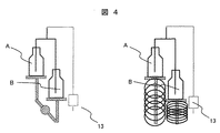
図4左図においては、試薬ボトルの溶液が用いられ、一方のボトルが軽量となった場合、2本のボトルは天秤に搭載されており、軽量であるボトルAがボトルBの重みにより高い位置に移動する。高い位置に液面が移動することにより位置エネルギーを得、試薬貯留槽13へはボトルAの溶液が送液される。
In the left figure of FIG. 4, when the solution in the reagent bottle is used and one of the bottles becomes light, the two bottles are mounted on the balance, and the lightweight bottle A is positioned higher due to the weight of the bottle B. Move to. When the liquid level moves to a higher position, potential energy is obtained, and the solution in the bottle A is sent to the
ボトルAの溶液がなくなるか、規定数の分析を終了し十分少量となったときには、ボトルBからの溶液供給が開始される。ボトルBの溶液がなくなるか規定数の分析を終了する前にボトルAを取り出し、その位置に別の新しいボトル(例えばボトルC)を設置することが望ましい。重量はボトルBを上回り、ボトルBは高い位置に移動し継続して試薬の供給はボトルBから行われる。 When the solution in the bottle A runs out, or when the specified number of analyzes are completed and the amount is sufficiently small, supply of the solution from the bottle B is started. It is desirable to remove the bottle A before the solution of the bottle B runs out or finish the specified number of analyzes and install another new bottle (for example, the bottle C) at that position. The weight exceeds the bottle B, and the bottle B moves to a higher position and the reagent is continuously supplied from the bottle B.
図4右図では、ボトルはバネと台座の上に搭載され、ボトル重量の相対的な軽重からボトル内の溶液液面の高低差が得られ、左図と同様の軽量であるボトルAがボトルBより高い位置に移動する。高い位置に液面が移動することにより位置エネルギーを得、試薬貯留槽13へはボトルAの溶液が送液される。
In the right diagram of FIG. 4, the bottle is mounted on a spring and a pedestal, and the difference in level of the solution liquid level in the bottle is obtained from the relative weight of the bottle weight. Move to a position higher than B. When the liquid level moves to a higher position, potential energy is obtained, and the solution in the bottle A is sent to the
ボトル内の溶液液面に高低を与える機構は、天秤,バネ,ゴム,シーソー等を利用したもの、あるいは、空気圧,油圧等を利用した機構等、搭載されたボトル重量により位置あるいは形状が可逆的に変化するものであればなんでも良い。 The mechanism that gives the liquid level in the bottle is reversible in position or shape depending on the weight of the mounted bottle, such as one using a balance, spring, rubber, seesaw, etc., or one using air pressure, hydraulic pressure, etc. Anything can be used as long as it changes.
このように、ボトルは使用中であれば他の未使用のボトルに比較して高い位置にあり、他のボトルが使用済みに容器であれば、溶液のあるボトルからの試薬供給がなされる。 Thus, if the bottle is in use, it is at a higher position than other unused bottles. If the other bottle is a used container, the reagent is supplied from the bottle with the solution.
なお、ボトルはボトル内のチューブを短くしキャップの個所が下方向にあっても良く、また、横置きされていても良い。また、ボトル内部の空気等の移動のため、気体移動路となる別のチューブを設けても良い。 In addition, the bottle may shorten the tube in a bottle and the location of a cap may be in the downward direction, and may be placed horizontally. Moreover, you may provide another tube used as a gas movement path for the movement of the air etc. inside a bottle.
11 試薬ボトル
12 チューブ
13 試薬貯留槽
14 電磁弁
15 シリンジ
16 反応容器
17 光電子増倍管(PMT)
30 反応容器
101 検体レーン
102 第1試薬ディスク外周
103 第1試薬ディスク内周
104 第2試薬ディスク
105 反応ディスク
106 光学検出ユニット
107 グリッパ
110 第3分注ピペット
111 第3分注ピペット可動範囲
112 第1分注ピペット
113 第1分注ピペット可動範囲
114 第2分注ピペット
115 第2分注ピペット可動範囲
A 試薬ボトル
B 試薬ボトル(A,Bは同一組成の試薬)
11
30
Claims (2)
該複数の液体容器設置位置に架設された液体容器の重量差に基づき、重量の小さい液体容器から先に前記液体容器から液体を吸引するように制御する制御機構を備えたことを特徴とする自動分析装置。 A liquid container installation position capable of installing a plurality of liquid containers containing the same liquid;
An automatic control system comprising a control mechanism for controlling to suck liquid from a liquid container having a small weight first, based on a weight difference between liquid containers installed at the plurality of liquid container installation positions. Analysis equipment.
前記重量差に基づき、重量の小さい液体容器から先に前記液体容器から液体を吸引する機構は、天秤,バネ圧,空気圧のいずれかにより重量が小さい液体容器が高い位置に位置付けられる機構と、
高い位置に位置付けられた液体容器から順次使用される機構と、
を備えたことを特徴とする自動分析装置。 The automatic analyzer according to claim 1, wherein
Based on the weight difference, a mechanism for sucking liquid from the liquid container first from a liquid container having a small weight is a mechanism in which a liquid container having a small weight is positioned at a high position by any one of a balance, spring pressure, and air pressure;
A mechanism sequentially used from a liquid container positioned at a high position;
An automatic analyzer characterized by comprising:
Priority Applications (1)
| Application Number | Priority Date | Filing Date | Title |
|---|---|---|---|
| JP2007224992A JP4857223B2 (en) | 2007-08-31 | 2007-08-31 | Automatic analyzer |
Applications Claiming Priority (1)
| Application Number | Priority Date | Filing Date | Title |
|---|---|---|---|
| JP2007224992A JP4857223B2 (en) | 2007-08-31 | 2007-08-31 | Automatic analyzer |
Publications (2)
| Publication Number | Publication Date |
|---|---|
| JP2009058317A true JP2009058317A (en) | 2009-03-19 |
| JP4857223B2 JP4857223B2 (en) | 2012-01-18 |
Family
ID=40554194
Family Applications (1)
| Application Number | Title | Priority Date | Filing Date |
|---|---|---|---|
| JP2007224992A Expired - Fee Related JP4857223B2 (en) | 2007-08-31 | 2007-08-31 | Automatic analyzer |
Country Status (1)
| Country | Link |
|---|---|
| JP (1) | JP4857223B2 (en) |
Cited By (3)
| Publication number | Priority date | Publication date | Assignee | Title |
|---|---|---|---|---|
| JP2013120161A (en) * | 2011-12-08 | 2013-06-17 | Hitachi High-Technologies Corp | Automatic analyzer |
| CN103657548A (en) * | 2012-08-31 | 2014-03-26 | 艾博生物医药(杭州)有限公司 | Method and equipment for automatically adding liquid reagent |
| WO2018173560A1 (en) * | 2017-03-23 | 2018-09-27 | 株式会社 日立ハイテクノロジーズ | Automatic analysis device |
Citations (3)
| Publication number | Priority date | Publication date | Assignee | Title |
|---|---|---|---|---|
| JPS60109052A (en) * | 1983-11-18 | 1985-06-14 | Sony Corp | Cassette type recording and reproducing device |
| JPH0943244A (en) * | 1995-07-31 | 1997-02-14 | Shimadzu Corp | Automatic chemical analizer |
| JPH10320056A (en) * | 1997-05-20 | 1998-12-04 | Kikuko Yamamoto | Constant amount liquid suction/discharge device |
-
2007
- 2007-08-31 JP JP2007224992A patent/JP4857223B2/en not_active Expired - Fee Related
Patent Citations (3)
| Publication number | Priority date | Publication date | Assignee | Title |
|---|---|---|---|---|
| JPS60109052A (en) * | 1983-11-18 | 1985-06-14 | Sony Corp | Cassette type recording and reproducing device |
| JPH0943244A (en) * | 1995-07-31 | 1997-02-14 | Shimadzu Corp | Automatic chemical analizer |
| JPH10320056A (en) * | 1997-05-20 | 1998-12-04 | Kikuko Yamamoto | Constant amount liquid suction/discharge device |
Cited By (5)
| Publication number | Priority date | Publication date | Assignee | Title |
|---|---|---|---|---|
| JP2013120161A (en) * | 2011-12-08 | 2013-06-17 | Hitachi High-Technologies Corp | Automatic analyzer |
| CN103657548A (en) * | 2012-08-31 | 2014-03-26 | 艾博生物医药(杭州)有限公司 | Method and equipment for automatically adding liquid reagent |
| WO2018173560A1 (en) * | 2017-03-23 | 2018-09-27 | 株式会社 日立ハイテクノロジーズ | Automatic analysis device |
| JPWO2018173560A1 (en) * | 2017-03-23 | 2019-12-19 | 株式会社日立ハイテクノロジーズ | Automatic analyzer |
| US11161118B2 (en) | 2017-03-23 | 2021-11-02 | Hitachi High-Tech Corporation | Automatic analysis device |
Also Published As
| Publication number | Publication date |
|---|---|
| JP4857223B2 (en) | 2012-01-18 |
Similar Documents
| Publication | Publication Date | Title |
|---|---|---|
| JP3464793B2 (en) | Automatic continuous random access analysis system and its components | |
| JP3439466B2 (en) | Automatic continuous random access analysis system and its components | |
| EP2581746B1 (en) | Sample analysis device and sample analysis method | |
| JP2018100983A (en) | Automatic clinical analyzer, and method for processing analytical test element in automatic clinical analyzer | |
| JP3003118B2 (en) | Method for providing a homogeneous reagent | |
| US20180180607A1 (en) | Analysis method and analyzer | |
| JP6313977B2 (en) | Sample analyzer and sample analysis method | |
| JP6335371B2 (en) | Immunoassay device and immunoassay method | |
| US20170059562A1 (en) | Immune measuring apparatus and immune measuring method | |
| JP4857223B2 (en) | Automatic analyzer | |
| JP2010032215A (en) | Autoanalyzer | |
| JP5031592B2 (en) | B / F separation cleaning method and B / F separation cleaning apparatus | |
| JP3507325B2 (en) | Sample analyzer and sample analysis method | |
| JP2011013148A (en) | Automatic analyzer and magnetic particle moving method | |
| US20190018029A1 (en) | Automated Analysis Device and Automated Analysis Method | |
| JP2014228385A (en) | Immunity test method and immunity test kit | |
| JP3816742B2 (en) | Sample analysis apparatus and method | |
| JP2001041964A (en) | Autoanalyzer | |
| WO2020166611A1 (en) | Analysis device | |
| JPH11101803A (en) | Immunoassay apparatus |
Legal Events
| Date | Code | Title | Description |
|---|---|---|---|
| A621 | Written request for application examination |
Free format text: JAPANESE INTERMEDIATE CODE: A621 Effective date: 20090826 |
|
| A521 | Written amendment |
Free format text: JAPANESE INTERMEDIATE CODE: A523 Effective date: 20090826 |
|
| A977 | Report on retrieval |
Free format text: JAPANESE INTERMEDIATE CODE: A971007 Effective date: 20110518 |
|
| A131 | Notification of reasons for refusal |
Free format text: JAPANESE INTERMEDIATE CODE: A131 Effective date: 20110524 |
|
| A521 | Written amendment |
Free format text: JAPANESE INTERMEDIATE CODE: A523 Effective date: 20110721 |
|
| TRDD | Decision of grant or rejection written | ||
| A01 | Written decision to grant a patent or to grant a registration (utility model) |
Free format text: JAPANESE INTERMEDIATE CODE: A01 Effective date: 20111004 |
|
| A01 | Written decision to grant a patent or to grant a registration (utility model) |
Free format text: JAPANESE INTERMEDIATE CODE: A01 |
|
| A61 | First payment of annual fees (during grant procedure) |
Free format text: JAPANESE INTERMEDIATE CODE: A61 Effective date: 20111031 |
|
| FPAY | Renewal fee payment (event date is renewal date of database) |
Free format text: PAYMENT UNTIL: 20141104 Year of fee payment: 3 |
|
| R150 | Certificate of patent or registration of utility model |
Ref document number: 4857223 Country of ref document: JP Free format text: JAPANESE INTERMEDIATE CODE: R150 Free format text: JAPANESE INTERMEDIATE CODE: R150 |
|
| S531 | Written request for registration of change of domicile |
Free format text: JAPANESE INTERMEDIATE CODE: R313531 |
|
| S533 | Written request for registration of change of name |
Free format text: JAPANESE INTERMEDIATE CODE: R313533 |
|
| R350 | Written notification of registration of transfer |
Free format text: JAPANESE INTERMEDIATE CODE: R350 |
|
| LAPS | Cancellation because of no payment of annual fees |