JP2009057977A - Injection nozzle for injecting fuel - Google Patents
Injection nozzle for injecting fuel Download PDFInfo
- Publication number
- JP2009057977A JP2009057977A JP2008221042A JP2008221042A JP2009057977A JP 2009057977 A JP2009057977 A JP 2009057977A JP 2008221042 A JP2008221042 A JP 2008221042A JP 2008221042 A JP2008221042 A JP 2008221042A JP 2009057977 A JP2009057977 A JP 2009057977A
- Authority
- JP
- Japan
- Prior art keywords
- nozzle
- injection nozzle
- fuel
- passage
- injection
- Prior art date
- Legal status (The legal status is an assumption and is not a legal conclusion. Google has not performed a legal analysis and makes no representation as to the accuracy of the status listed.)
- Abandoned
Links
- 238000002347 injection Methods 0.000 title claims abstract description 128
- 239000007924 injection Substances 0.000 title claims abstract description 128
- 239000000446 fuel Substances 0.000 title claims abstract description 92
- 238000002485 combustion reaction Methods 0.000 claims description 22
- 238000007664 blowing Methods 0.000 claims description 13
- 239000007788 liquid Substances 0.000 claims 1
- 239000000243 solution Substances 0.000 abstract 1
- 230000006835 compression Effects 0.000 description 6
- 238000007906 compression Methods 0.000 description 6
- 230000036316 preload Effects 0.000 description 4
- 238000010276 construction Methods 0.000 description 3
- 238000007599 discharging Methods 0.000 description 3
- 239000004071 soot Substances 0.000 description 3
- 238000004519 manufacturing process Methods 0.000 description 2
- 238000000926 separation method Methods 0.000 description 2
- 230000001419 dependent effect Effects 0.000 description 1
- 238000010586 diagram Methods 0.000 description 1
- 238000002474 experimental method Methods 0.000 description 1
- 239000007921 spray Substances 0.000 description 1
Images


Classifications
-
- F—MECHANICAL ENGINEERING; LIGHTING; HEATING; WEAPONS; BLASTING
- F02—COMBUSTION ENGINES; HOT-GAS OR COMBUSTION-PRODUCT ENGINE PLANTS
- F02M—SUPPLYING COMBUSTION ENGINES IN GENERAL WITH COMBUSTIBLE MIXTURES OR CONSTITUENTS THEREOF
- F02M55/00—Fuel-injection apparatus characterised by their fuel conduits or their venting means; Arrangements of conduits between fuel tank and pump F02M37/00
- F02M55/002—Arrangement of leakage or drain conduits in or from injectors
-
- F—MECHANICAL ENGINEERING; LIGHTING; HEATING; WEAPONS; BLASTING
- F02—COMBUSTION ENGINES; HOT-GAS OR COMBUSTION-PRODUCT ENGINE PLANTS
- F02M—SUPPLYING COMBUSTION ENGINES IN GENERAL WITH COMBUSTIBLE MIXTURES OR CONSTITUENTS THEREOF
- F02M61/00—Fuel-injectors not provided for in groups F02M39/00 - F02M57/00 or F02M67/00
- F02M61/16—Details not provided for in, or of interest apart from, the apparatus of groups F02M61/02 - F02M61/14
- F02M61/18—Injection nozzles, e.g. having valve seats; Details of valve member seated ends, not otherwise provided for
-
- F—MECHANICAL ENGINEERING; LIGHTING; HEATING; WEAPONS; BLASTING
- F02—COMBUSTION ENGINES; HOT-GAS OR COMBUSTION-PRODUCT ENGINE PLANTS
- F02M—SUPPLYING COMBUSTION ENGINES IN GENERAL WITH COMBUSTIBLE MIXTURES OR CONSTITUENTS THEREOF
- F02M47/00—Fuel-injection apparatus operated cyclically with fuel-injection valves actuated by fluid pressure
- F02M47/02—Fuel-injection apparatus operated cyclically with fuel-injection valves actuated by fluid pressure of accumulator-injector type, i.e. having fuel pressure of accumulator tending to open, and fuel pressure in other chamber tending to close, injection valves and having means for periodically releasing that closing pressure
- F02M47/027—Electrically actuated valves draining the chamber to release the closing pressure
-
- F—MECHANICAL ENGINEERING; LIGHTING; HEATING; WEAPONS; BLASTING
- F02—COMBUSTION ENGINES; HOT-GAS OR COMBUSTION-PRODUCT ENGINE PLANTS
- F02M—SUPPLYING COMBUSTION ENGINES IN GENERAL WITH COMBUSTIBLE MIXTURES OR CONSTITUENTS THEREOF
- F02M61/00—Fuel-injectors not provided for in groups F02M39/00 - F02M57/00 or F02M67/00
- F02M61/04—Fuel-injectors not provided for in groups F02M39/00 - F02M57/00 or F02M67/00 having valves, e.g. having a plurality of valves in series
- F02M61/10—Other injectors with elongated valve bodies, i.e. of needle-valve type
-
- F—MECHANICAL ENGINEERING; LIGHTING; HEATING; WEAPONS; BLASTING
- F02—COMBUSTION ENGINES; HOT-GAS OR COMBUSTION-PRODUCT ENGINE PLANTS
- F02M—SUPPLYING COMBUSTION ENGINES IN GENERAL WITH COMBUSTIBLE MIXTURES OR CONSTITUENTS THEREOF
- F02M61/00—Fuel-injectors not provided for in groups F02M39/00 - F02M57/00 or F02M67/00
- F02M61/16—Details not provided for in, or of interest apart from, the apparatus of groups F02M61/02 - F02M61/14
-
- F—MECHANICAL ENGINEERING; LIGHTING; HEATING; WEAPONS; BLASTING
- F02—COMBUSTION ENGINES; HOT-GAS OR COMBUSTION-PRODUCT ENGINE PLANTS
- F02M—SUPPLYING COMBUSTION ENGINES IN GENERAL WITH COMBUSTIBLE MIXTURES OR CONSTITUENTS THEREOF
- F02M63/00—Other fuel-injection apparatus having pertinent characteristics not provided for in groups F02M39/00 - F02M57/00 or F02M67/00; Details, component parts, or accessories of fuel-injection apparatus, not provided for in, or of interest apart from, the apparatus of groups F02M39/00 - F02M61/00 or F02M67/00; Combination of fuel pump with other devices, e.g. lubricating oil pump
- F02M63/0012—Valves
- F02M63/0031—Valves characterized by the type of valves, e.g. special valve member details, valve seat details, valve housing details
- F02M63/0047—Four-way valves or valves with more than four ways
-
- F—MECHANICAL ENGINEERING; LIGHTING; HEATING; WEAPONS; BLASTING
- F02—COMBUSTION ENGINES; HOT-GAS OR COMBUSTION-PRODUCT ENGINE PLANTS
- F02M—SUPPLYING COMBUSTION ENGINES IN GENERAL WITH COMBUSTIBLE MIXTURES OR CONSTITUENTS THEREOF
- F02M63/00—Other fuel-injection apparatus having pertinent characteristics not provided for in groups F02M39/00 - F02M57/00 or F02M67/00; Details, component parts, or accessories of fuel-injection apparatus, not provided for in, or of interest apart from, the apparatus of groups F02M39/00 - F02M61/00 or F02M67/00; Combination of fuel pump with other devices, e.g. lubricating oil pump
- F02M63/0012—Valves
- F02M63/0031—Valves characterized by the type of valves, e.g. special valve member details, valve seat details, valve housing details
- F02M63/0049—Combined valve units, e.g. for controlling pumping chamber and injection valve
-
- F—MECHANICAL ENGINEERING; LIGHTING; HEATING; WEAPONS; BLASTING
- F02—COMBUSTION ENGINES; HOT-GAS OR COMBUSTION-PRODUCT ENGINE PLANTS
- F02M—SUPPLYING COMBUSTION ENGINES IN GENERAL WITH COMBUSTIBLE MIXTURES OR CONSTITUENTS THEREOF
- F02M61/00—Fuel-injectors not provided for in groups F02M39/00 - F02M57/00 or F02M67/00
- F02M61/16—Details not provided for in, or of interest apart from, the apparatus of groups F02M61/02 - F02M61/14
- F02M61/18—Injection nozzles, e.g. having valve seats; Details of valve member seated ends, not otherwise provided for
- F02M61/1806—Injection nozzles, e.g. having valve seats; Details of valve member seated ends, not otherwise provided for characterised by the arrangement of discharge orifices, e.g. orientation or size
- F02M61/182—Discharge orifices being situated in different transversal planes with respect to valve member direction of movement
-
- F—MECHANICAL ENGINEERING; LIGHTING; HEATING; WEAPONS; BLASTING
- F02—COMBUSTION ENGINES; HOT-GAS OR COMBUSTION-PRODUCT ENGINE PLANTS
- F02M—SUPPLYING COMBUSTION ENGINES IN GENERAL WITH COMBUSTIBLE MIXTURES OR CONSTITUENTS THEREOF
- F02M63/00—Other fuel-injection apparatus having pertinent characteristics not provided for in groups F02M39/00 - F02M57/00 or F02M67/00; Details, component parts, or accessories of fuel-injection apparatus, not provided for in, or of interest apart from, the apparatus of groups F02M39/00 - F02M61/00 or F02M67/00; Combination of fuel pump with other devices, e.g. lubricating oil pump
- F02M63/02—Fuel-injection apparatus having several injectors fed by a common pumping element, or having several pumping elements feeding a common injector; Fuel-injection apparatus having provisions for cutting-out pumps, pumping elements, or injectors; Fuel-injection apparatus having provisions for variably interconnecting pumping elements and injectors alternatively
- F02M63/0205—Fuel-injection apparatus having several injectors fed by a common pumping element, or having several pumping elements feeding a common injector; Fuel-injection apparatus having provisions for cutting-out pumps, pumping elements, or injectors; Fuel-injection apparatus having provisions for variably interconnecting pumping elements and injectors alternatively for cutting-out pumps or injectors in case of abnormal operation of the engine or the injection apparatus, e.g. over-speed, break-down of fuel pumps or injectors ; for cutting-out pumps for stopping the engine
- F02M63/0215—Fuel-injection apparatus having several injectors fed by a common pumping element, or having several pumping elements feeding a common injector; Fuel-injection apparatus having provisions for cutting-out pumps, pumping elements, or injectors; Fuel-injection apparatus having provisions for variably interconnecting pumping elements and injectors alternatively for cutting-out pumps or injectors in case of abnormal operation of the engine or the injection apparatus, e.g. over-speed, break-down of fuel pumps or injectors ; for cutting-out pumps for stopping the engine by draining or closing fuel conduits
Landscapes
- Engineering & Computer Science (AREA)
- Chemical & Material Sciences (AREA)
- Combustion & Propulsion (AREA)
- Mechanical Engineering (AREA)
- General Engineering & Computer Science (AREA)
- Physics & Mathematics (AREA)
- Fluid Mechanics (AREA)
- Fuel-Injection Apparatus (AREA)
Abstract
Description
本発明は、請求項1の前段部分によるディーゼル・エンジン内へ燃料を噴射するための噴射ノズルに関し、及び、この種類の少なくとも1つの噴射ノズルを備えるディーゼル・エンジン、特に、大型2ストローク・ディーゼル・エンジンに関する。 The invention relates to an injection nozzle for injecting fuel into a diesel engine according to the front part of claim 1 and to a diesel engine comprising at least one injection nozzle of this kind, in particular a large two-stroke diesel engine. Related to the engine.
例えば、船舶及び発電所で使用されるような、いくつかのディーゼル・エンジン、特に、従来構造の大型2ストローク・ディーゼル・エンジンでは、ノズル本体と、それに接続されたノズル・ヘッドとをもち、シリンダ内に配置されたディーゼル・エンジンの燃焼スペースに燃料を噴射するために、ノズル・ヘッドが1つ又は複数のノズル開口をもつ噴射ノズルが使用される。この種の噴射ノズルはノズル本体の内部に配置された弁ニードル及び弁座を備える噴射弁をさらに含み、噴射弁はノズル本体内及びノズル・ヘッド内に形成された通路を介してノズル開口に接続され、ノズル開口への燃料供給を制御するために、通路は弁ニードルと協働する。さらに、噴射ノズルは、通常、弁ニードルを動かすために、シリンダ・ボア内に移動可能に配置されたピストンと、噴射ノズルのところで支配的な燃料圧力が低い間、噴射ノズルからの滴下を防止するために、ピストンに作用し、ピストンに接続された弁ニードルを弁座に押しつける圧縮ばねとを有している。噴射ノズルが開く圧力は、ばねの予荷重によって、各噴射ノズルに対して調整される。 For example, some diesel engines, such as those used in ships and power plants, especially large two-stroke diesel engines of conventional construction, have a nozzle body and a nozzle head connected to the cylinder, An injection nozzle with a nozzle head having one or more nozzle openings is used to inject fuel into the combustion space of a diesel engine located within. This type of injection nozzle further comprises an injection valve with a valve needle and a valve seat arranged inside the nozzle body, the injection valve being connected to the nozzle opening via a passage formed in the nozzle body and in the nozzle head And the passage cooperates with the valve needle to control the fuel supply to the nozzle opening. In addition, the injection nozzle typically prevents dripping from the injection nozzle while the dominant fuel pressure at the injection nozzle is low and the piston movably disposed in the cylinder bore to move the valve needle. For this purpose, it has a compression spring which acts on the piston and presses the valve needle connected to the piston against the valve seat. The pressure at which the injection nozzle opens is adjusted for each injection nozzle by the preload of the spring.
燃料噴射ノズルの弁座は、通常、1つ又は複数のノズル穴から離れて配置される。その理由は、弁座は、高い噴射圧力から生じる圧力負荷に耐えるために、十分に強く支持されなければならないからである。これは、比較的大きなスペースを取る、対応した強固な構成方法を必要とする。しかし、複数の噴射ノズルが、通常、各シリンダに提供されるので、スペースの理由で、燃焼スペースのすぐ近くに配置される噴射ノズルの領域を対応して強固に寸法決めすることは難しい。さらに、燃料噴射ノズルの弁座が、通常のように、ノズル開口から離れて配置されないならば、2ストローク・ディーゼル・エンジンのシリンダ・ヘッドは、通常、非常に厚いので、噴射ノズルのこれらの領域を、もはやほとんど冷却することができず、したがって動作中、極めて高温にさらされる。弁座と対応するノズル開口の間の十分な距離は、弁座が動作中に熱くなりすぎず、それらが、すべての動作条件で完全に機能することを保証する。 The fuel injection nozzle valve seat is typically located away from the nozzle hole or holes. The reason for this is that the valve seat must be supported sufficiently strongly to withstand the pressure load resulting from the high injection pressure. This requires a corresponding robust construction method that takes up a relatively large space. However, since a plurality of injection nozzles are usually provided for each cylinder, for reasons of space, it is difficult to correspondingly and strongly dimension the region of the injection nozzle that is located in the immediate vicinity of the combustion space. Further, if the fuel injection nozzle valve seat is not normally located away from the nozzle opening, the cylinder head of a two-stroke diesel engine is usually very thick, so these areas of the injection nozzle Can no longer be cooled anymore and are therefore exposed to very high temperatures during operation. A sufficient distance between the valve seat and the corresponding nozzle opening ensures that the valve seat does not get too hot during operation and that they are fully functional under all operating conditions.
上で説明された構成方法により、弁ニードルを閉じた後、弁座とノズル開口の間の通路内に残る燃料の量は相当である。通路内に残る燃料は、熱くなり、膨張フェーズの間に、圧力が下がるために、燃焼スペースに漏れ得る。このときにおいては、燃焼スペースの温度は、完全燃焼にはもはや十分でないように低下している。実験は、通路内に残る燃料の量がディーゼル・エンジンの煤の放出にかなりの影響を与えることを示している。 With the construction method described above, the amount of fuel remaining in the passage between the valve seat and the nozzle opening after closing the valve needle is substantial. The fuel remaining in the passage becomes hot and can leak into the combustion space due to the pressure drop during the expansion phase. At this time, the temperature of the combustion space has dropped so that it is no longer sufficient for complete combustion. Experiments have shown that the amount of fuel remaining in the passage has a significant impact on diesel engine soot emissions.
WO 93/07386には、長手方向ボアの形状の通路とノズル開口とをもち、且つノズル・ヘッド及びノズル開口への燃料供給を開閉するために、弁座と閉鎖部品とを有する噴射弁をもつノズル・ヘッドを備える噴射ノズルが記載されている。WO 93/07386による噴射ノズルは、スリーブとして形成された閉鎖要素をさらに含み、閉鎖要素は、ノズル開口を開閉するために、噴射ノズルの閉鎖部品に固定的に接続されている。追加の閉鎖要素により、膨張フェーズの間、ノズル・ヘッドの長手方向ボアからの望ましくない燃料の漏れを防止できる。噴射弁の閉鎖部品と追加の閉鎖要素の間の固定接続による製造公差に高い要求がなされ、噴射弁の弁座内の断面形状とノズル開口の変化は、燃料圧力がスリーブをあまり膨張させ、したがってそれを破損させないように互いに正確に整合されなければならない。 WO 93/07386 has an injection valve with a passage in the form of a longitudinal bore and a nozzle opening and having a valve seat and a closing part for opening and closing the fuel supply to the nozzle head and nozzle opening. An injection nozzle with a nozzle head is described. The injection nozzle according to WO 93/07386 further comprises a closing element formed as a sleeve, which is fixedly connected to the closing part of the injection nozzle for opening and closing the nozzle opening. An additional closure element prevents unwanted fuel leakage from the longitudinal bore of the nozzle head during the expansion phase. High demands are made on manufacturing tolerances due to the fixed connection between the closing part of the injection valve and the additional closing element, and changes in the cross-sectional shape and nozzle opening in the valve seat of the injection valve cause the fuel pressure to expand too much and thus the sleeve It must be precisely aligned with each other so as not to damage it.
本発明の目的は、製造がより簡単であり、噴射弁の弁座内の断面形状の変化と、1つ又は複数のノズル開口のところでの断面形状の変化との間で決定的な整合を必要としない、ディーゼル・エンジン、特に、大型2ストローク・ディーゼル・エンジン内の燃料の噴射用の噴射ノズルを利用できるようにすることである。さらなる目的は、この種類の少なくとも1つの噴射ノズルを備えるディーゼル・エンジン、特に、大型2ストローク・ディーゼルエンジンを利用できるようにすることである。 The object of the present invention is simpler to manufacture and requires a critical match between the change in cross-sectional shape within the valve seat of the injection valve and the change in cross-sectional shape at one or more nozzle openings. It is to make available an injection nozzle for the injection of fuel in diesel engines, in particular large two-stroke diesel engines. A further object is to be able to utilize diesel engines with at least one injection nozzle of this kind, in particular large two-stroke diesel engines.
この目的は、請求項1で定義される噴射ノズル及び請求項10で定義されるディーゼル・エンジンによって本発明にしたがって達成される。
This object is achieved according to the invention by means of an injection nozzle as defined in claim 1 and a diesel engine as defined in
ディーゼル・エンジン、特に、大型2ストローク・ディーゼル・エンジン内に燃料を噴射するための、本発明による噴射ノズルは、ディーゼル・エンジンの燃焼スペース内に燃料を噴射するために、ノズル本体と、それに接続された、1つ又は複数のノズル開口を備えるノズル・ヘッドとを含む。噴射ノズルは噴射弁をさらに含み、噴射弁はノズル開口への燃料供給を制御するために、ノズル本体の内部に配置された弁ニードル及び弁座を有し、噴射弁は、ノズル本体の中及び/又はノズル・ヘッドの中に形成された通路であって、弁ニードルと協働する通路を介してノズル開口に接続されている。本発明による噴射ノズルは、通路及びデバイスに取り付けられた管路を空にするためのデバイスをさらに含み、噴射ノズルが閉じたとき、管路がそれを空にするために通路に接続される。 An injection nozzle according to the present invention for injecting fuel into a diesel engine, in particular a large two-stroke diesel engine, is connected to the nozzle body for injecting fuel into the combustion space of the diesel engine And a nozzle head with one or more nozzle openings. The injection nozzle further includes an injection valve, the injection valve having a valve needle and a valve seat disposed inside the nozzle body for controlling fuel supply to the nozzle opening, the injection valve being located in the nozzle body and A passage formed in the nozzle head and connected to the nozzle opening via a passage cooperating with the valve needle. The injection nozzle according to the invention further comprises a device for emptying the passage and the conduit attached to the device, and when the injection nozzle is closed, the conduit is connected to the passage to empty it.
有利な実施例では、空にするためのデバイスは、2つの管路を介して燃料を排出するために、通路に接続された管路と接続することができるドレン管路を含む。 In an advantageous embodiment, the emptying device includes a drain line that can be connected to a line connected to the passage for discharging fuel through the two lines.
有利な実施例では、空にするためのデバイスは、燃焼スペース内に存在する過剰圧力の助けによって、通路内の燃料を排出するために、例えば、2つの上で挙げられた管路の間に配置することができる滑り弁を含む。 In an advantageous embodiment, the device for emptying is used, for example, between two above-mentioned lines to discharge the fuel in the passage with the help of excess pressure present in the combustion space. Includes a slip valve that can be placed.
さらに有利な変形では、空にするためのデバイスは、通路から燃料を受け、及び/又はそれを排出するために、ピストンを備えるシリンダを含む。シリンダ及びその中で移動可能に案内されるピストンは、それぞれ、異なる直径を備える2つのセクションをもち、シリンダを、より大きい直径の側で燃料供給管路に接続でき、反対の側で通路に接続された管路に接続できる。低い燃料圧力又は燃料圧力がない場合に、休止位置にこのピストンを動かすために、ピストンに作用するばねを提供することがさらに可能である。 In a further advantageous variant, the device for emptying comprises a cylinder with a piston for receiving and / or discharging fuel from the passage. The cylinder and piston movably guided therein each have two sections with different diameters, allowing the cylinder to be connected to the fuel supply line on the larger diameter side and to the passage on the opposite side Can be connected to the pipeline. It is further possible to provide a spring acting on the piston to move the piston to the rest position in the absence of low fuel pressure or fuel pressure.
通路を空にするためのデバイスは、通路から生じる燃料から排気ガスを分離するために、例えば分離容器などの分離器を任意選択で含むことができる。 The device for emptying the passage can optionally include a separator, such as a separation vessel, for separating the exhaust gas from the fuel originating from the passage.
さらに有利な実施例では、ノズル開口を通って、通路内に燃料を吹き出すための吹き出しデバイスとして、空にするためにデバイスを形成することができる。例えば、吹き出しデバイスは、圧縮空気供給管路及び/又は、圧縮空気溜め又は圧縮空気供給部に接続され又は接続することができる逆止弁を介して、圧縮空気を供給され得る圧縮空気溜めを含むことができる。圧縮空気供給管路又は圧縮空気溜め又は逆止弁を、任意選択で、通路に接続された管路に接続し、又は接続することができる。必要ならば、吹き出しデバイスは、例えば、圧縮空気供給部又は圧縮空気溜めに接続された滑り弁を含むことができ、例えば、圧縮空気溜めの圧縮空気供給を制御するために、供給された燃料の圧力によって、それを、動作することができる。 In a further advantageous embodiment, the device can be formed to empty as a blowing device for blowing fuel through the nozzle opening and into the passage. For example, the blowing device includes a compressed air reservoir that may be supplied with compressed air via a compressed air supply line and / or a check valve connected to or connectable to a compressed air reservoir or compressed air supply. be able to. A compressed air supply line or a compressed air reservoir or check valve is optionally connected to or connected to the line connected to the passage. If necessary, the blowing device can include, for example, a compressed air supply or a slip valve connected to the compressed air reservoir, for example, to control the compressed air supply of the compressed air reservoir. It can be operated by pressure.
上で説明した実施例及び変形とは独立して、必要ならば、噴射ノズルは、弁ニードルと動作可能に接続した第1ピストンと、第1ピストンと動作可能に接続した第2ピストンとを、2つのピストンを備える噴射ノズルの開閉を制御するために、さらに含むことができる。 Independently of the embodiments and variations described above, if necessary, the injection nozzle includes a first piston operably connected to the valve needle and a second piston operably connected to the first piston. Further control can be included to control the opening and closing of the injection nozzle with two pistons.
本発明は、上で説明された実施例及び変形の1つ又は複数によって、燃料を噴射するための少なくとも1つの噴射ノズルをディーゼル・エンジン、特に大型2ストローク・ディーゼル・エンジンをさらに含む。 The present invention further includes a diesel engine, in particular a large two-stroke diesel engine, with at least one injection nozzle for injecting fuel according to one or more of the embodiments and variations described above.
弁座とノズル開口との間にある通路を空にするためのデバイスのおかげで、噴射弁が閉じたとき、上で説明された噴射ノズルにおいて、通路を空にすることができ、噴射休止期間における、通路からの燃料の望ましくない漏れを避けることができる。したがって、そうでない場合に、膨張フェーズの間の燃料の不完全燃焼で起こるはずの煤の放出が起こらない。上で説明された噴射ノズルが、もっぱら、標準部品及び/又は簡単に製造できる部品を含むことはさらなる利点である。 Thanks to the device for emptying the passage between the valve seat and the nozzle opening, when the injection valve is closed, in the injection nozzle described above, the passage can be empty and the injection pause period The undesirable leakage of fuel from the passageway can be avoided. Thus, there will be no soot release that would otherwise occur with incomplete combustion of the fuel during the expansion phase. It is a further advantage that the injection nozzle described above contains exclusively standard parts and / or parts that can be easily manufactured.
実施例及び変形の上の説明は、例としての役割を果たすだけにすぎない。さらに有利な実施例は、従属請求項及び図面に記載される。さらに、本発明の範囲の内部で、説明され図示された実施例及び変形からの個別の特徴を、新しい実施例を形成するために互いに組み合わせることができる。 The above description of the embodiments and variants serves only as an example. Further advantageous embodiments are described in the dependent claims and the drawings. Furthermore, within the scope of the invention, the individual features from the embodiments and variants described and illustrated can be combined with one another to form new embodiments.
本発明は、実施例の助けによって、又図面の助けによって、以下に、より詳細に説明される。 The invention is explained in more detail below with the aid of embodiments and with the aid of the drawings.
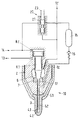
図1は、本発明による、ディーゼル・エンジン、特に、大型2ストローク・ディーゼル・エンジン内の燃料を噴射するための噴射ノズル10の実施例の概略図を示す。噴射ノズル10は、ノズル本体2と、それに接続されたノズル・ヘッド3とを含み、ノズル・ヘッド3は、ディーゼル・エンジンの燃焼スペース内に燃料を噴射するために、1つ又は複数のノズル開口4.1、4.2をもつ。噴射ノズルは、ノズル本体2の内部に配置された弁ニードル6及び弁座7を備える噴射弁をさらに含み、噴射弁はノズル本体の中及びノズル・ヘッドの中に形成された通路5.1、5.2を介して、ノズル開口4.1、4.2に接続され、該通路はノズル開口への供給を制御するために、弁ニードル6と協働する。実施例の噴射ノズルは、前記通路5.1、5.2を空にするためのデバイス15、16と、該デバイスに取り付けられた管路17をさらに含み、噴射ノズルが閉じたとき、管路17はそれを空にするために前記通路と連通する。
FIG. 1 shows a schematic diagram of an embodiment of an
有利な実施例では、空にするためのデバイスは、ノズル開口4.1、4.2を通って前記通路5.1、5.2内の燃料を吹き出すために、吹き出しデバイス15、16として形成される。吹き出しデバイスは、例えば、圧縮空気供給管路14を介して圧縮空気を供給されることができる圧縮空気溜め15及び/又は圧縮空気溜め又は圧縮空気供給部に接続され又はそれらに結合することができる逆止弁16を含むことができ、圧縮空気供給部14又は圧縮空気溜め15又は逆止弁16を、必要ならば、前記通路に連通する管路17に接続又はそれらに結合することができる。圧縮空気供給部によって送られる圧縮空気は、有利には、噴射弁が閉じたとき、燃焼スペース内に存在する圧力より高圧力、又は燃焼スペースの最大圧力より高圧力をもつ。圧縮空気の圧力は、通常、10000000パスカルと30000000パスカル(100バールと300バール)の間又は15000000パスカルと25000000パスカル(150バールと250バール)の間にある。
In an advantageous embodiment, the emptying device is formed as a blowing
有利な変形では、圧縮空気溜めは、噴射前及び/又は噴射中、圧縮空気で満たされる。弁ニードル6を閉じた後、前記通路5.1、5.2の圧力は下がり、圧縮空気溜めは、逆止弁16を介して、管路17、前記通路5.1、5.2及び、燃焼スペースへの1つ又は複数のノズル開口4.1、4.2を空にし、有利には、弁ニードル6を閉じた直後に、前記通路5.1、5.2内の燃料は、押し出され、圧縮空気の助けで霧状にされる。
In an advantageous variant, the compressed air reservoir is filled with compressed air before and / or during the injection. After closing the
吹き出しデバイスは、必要ならば、例えば、圧縮空気供給部14及び圧縮空気溜め15に接続される滑り弁20をさらに含み、滑り弁20は、例えば、圧縮空気溜めの圧縮空気供給を制御するために、供給された燃料の圧力によって運転されうる。滑り弁20が供給された燃料の圧力によって作動されるならば、滑り弁20は、有利に、燃料供給部12’に接続され、有利に、噴射弁の燃料供給部12にも接続される。制御弁20は、必要ならば、移動可能なスライダ21及び/又はリセットばね23を含むことができる。好ましい変形では、吹き出しデバイス及び/又は滑り弁20は、噴射弁10の中又は噴射弁10に配置される。滑り弁20の助けで、デバイスを圧縮空気で満たすために、圧縮空気供給部14を、噴射の始め又は終りに、短時間、圧縮空気溜め15に接続することができる。
The blow-out device further includes a
上で説明した実施例及び変形とは独立して、噴射ノズルは、例えば、ノズル本体2内の第1シリンダ・ボア内に移動可能に配置され、弁ニードル6と動作可能な接続にある又はそれに接続された第1ピストン8.1と、例えば、ノズル本体2内の第2シリンダ・ボア内に移動可能に配置され、第1ピストンと動作可能な接続にある又はそれに接続された第2ピストン8.2とを、2つのピストンを備える噴射弁の開閉を制御するために、さらに含むことができる。第2ピストンの直径は、通常、第1ピストンの直径より大きい。第1ピストン8.1に、例えば、噴射弁ノズルの燃料供給12を介して、供給された燃料の圧力で負荷をかけることができ、第2ピストン8.2を、例えば、加圧空気供給14を介して、圧縮空気で満たすことができる。必要ならば、漏れオイル管路13を、第1ピストンの領域に圧力除去のために提供することができる。エンジンが切られたとき、弁ニードル12に最小の閉じる力を加えるために、圧縮ばねを、図1には示されていない従来の噴射ノズルにおけるように、提供することができ、圧縮ばねを、従来の噴射ノズルと比べて、かなり弱く、又スペースを節約できるように設計することができる。噴射弁の開口圧力への影響はわずかであるので、圧縮ばねの予荷重を、調整可能である必要はない。
Independently of the embodiments and variants described above, the injection nozzle is, for example, movably arranged in a first cylinder bore in the
第1ピストン8.1に作用する燃料圧力の力が、第2ピストン8.2に作用する圧縮空気の力を、もし適用可能ならば、圧縮ばねの力を超えるとすぐに、噴射弁は開かれる。このようにして、動作では、その圧力で噴射弁が開く、開口圧力とも呼ばれる燃料圧力を、圧縮空気の圧力の助けで制御することができる。ディーゼル・エンジンのすべての噴射ノズルは、有利に、同じ圧縮空気供給から供給されるので、開口圧力の個々の調節を省くことができる。 As soon as the force of the fuel pressure acting on the first piston 8.1 exceeds the force of the compressed air acting on the second piston 8.2, if applicable, the injection valve opens. It is. In this way, in operation, the fuel pressure, also called opening pressure, at which the injection valve opens, can be controlled with the aid of compressed air pressure. All injection nozzles of the diesel engine are advantageously supplied from the same compressed air supply, so that individual adjustment of the opening pressure can be dispensed with.
図2は、本発明による、噴射ノズル10の第2実施例の概略図を示す。噴射ノズル10は、ノズル本体2と、それに接続されたノズル・ヘッド3とを含み、ノズル・ヘッド3は、ディーゼル・エンジンの燃焼スペース内に燃料を噴射するために、1つ又は複数のノズル開口4.1、4.2をもつ。噴射ノズルは、ノズル本体の内部に配置された弁ニードル6及び弁座7を備える噴射弁をさらに含み、弁ニードル6は、ノズル本体の中及びノズル・ヘッドの中に形成された通路5.1、5.2を介して、ノズル開口4.1、4.2に接続され、前記通路は、ノズル開口への燃料供給を制御するために、弁ニードル6と協働する。該実施例の噴射ノズルは、通路5.1、5.2を空にするためのデバイス18、18aと、それに接続された管路17をさらに含み、噴射弁が閉じたとき、前記管路17は、空にするために、前記通路と連通する。
FIG. 2 shows a schematic view of a second embodiment of the
有利な実施例では、空にするためのデバイスは、2つの管路を介して、前記通路内の燃料を排出するために、特に、燃焼スペース内に存在する過剰圧力の助けによって、それを排出するために、通路5.1、5.2と連通する管路17と接続することができるドレン管路18を含む。
In an advantageous embodiment, the device for emptying exhausts the fuel in the passage through two lines, in particular with the help of excess pressure present in the combustion space. In order to do so, it includes a
図2に示されるように、空にするためのデバイスは、必要ならば、通路から燃料を受け、及び/又はそれを排出するために、ピストン21.1、21.2を備えるシリンダ20、20.1、20.2を含むことができる。シリンダ及びその中に移動可能に案内されるピストンは、それぞれ、異なる直径を備える2つのセクション20.1、20.2及び21.1、21.2をもち、前記通路内の燃料を吸い込み、及び/又はそれを受けるために、シリンダを、より大きい直径の側で、燃料供給12’に接続でき、反対の側で、前記通路に接続された管路17に接続できる。この接続では、管路の体積を小さく保つために、弁ニードル6の中及び/又は弁ニードル6に接続された作動ピストン8の中に、管路17を形成することが可能である。さらに、必要ならば、燃料供給管路12’を、噴射弁の燃料供給12に接続することができる。低い燃料圧力又は燃料圧力がない場合に、静止位置に、このピストンを動かすために、ピストン21.1、21.2に作用するばね23を提供することがさらに可能である。
As shown in FIG. 2, the device for emptying
有利な実施例では、ピストン21.1、21.2は、下向きに移動し、燃料圧力が上昇するが弁ニードルは閉じたままで、それによって、必要ならば、燃料がシリンダから前記通路に押し出される。弁ニードルが開いたとき、上下のセクションの異なる直径のため、及び弁座7内の圧力損失のため、ピストンは低い位置のままである。この位置で、ドレン管路17をブリードするために、ドレン管路18への接続を、絞りを介して、もたらすことができる。この目的で、例えば、図2に示されるように、ピストン21.2は通路22を備えることができ、シリンダ20.2は、低い位置では、通路20・2に開き、絞り18aに接続される、出口開口を備えることができる。燃料圧力が下がるとすぐに、まず、弁ニードル6が閉じ、それからピストン21.1、21.2が、ばね23によって、高い位置に動かされ、燃焼スペ―スの圧力が上昇し、それによって、燃料が吸い込まれ、及び/又は通路からシリンダへと押し出される。ピストンは、燃料圧力が次に上がるまで、すなわち次の噴射まで、高い位置に留まる。必要ならば、吸い込まれた又は受けた燃料をシリンダから排出するために、さらなる出口開口を、ドレン管路18に接続されたシリンダに提供できる。
In an advantageous embodiment, the pistons 21.1, 21.2 move downward and the fuel pressure rises but the valve needle remains closed so that, if necessary, fuel is pushed out of the cylinder into the passage. . When the valve needle is opened, the piston remains in a low position due to the different diameters of the upper and lower sections and due to the pressure loss in the
図3は、本発明による噴射ノズル10の第3実施例の概略図を示す。噴射ノズル10は、ノズル本体2と、それに接続されたノズル・ヘッド3とを含み、ノズル・ヘッド3は、ディーゼル・エンジンの燃焼スペース内に燃料を噴射するために、1つ又は複数のノズル開口4.1、4.2をもつ。噴射ノズルは、ノズル本体2の内部に配置された弁ニードル6及び弁座7を備える噴射弁をさらに含み、弁ニードル6は、ノズル本体内及びノズル・ヘッド内に形成された通路5.1、5.2を介して、ノズル開口4.1、4.2に接続され、該通路は、ノズル開口への燃料供給を制御するために、弁ニードル6と協働する。実施例の噴射ノズルは、前記通路5.1、5.2を空にするためのデバイス18、18a、19、19a、20と、それに接続された管路17をさらに含み、噴射弁が閉じたとき、管路17は空にするために通路と連通する。
FIG. 3 shows a schematic view of a third embodiment of the
有利な実施例では、空にするためのデバイスは、2つの管路を介して、通路内の燃料を排出するために、特に、燃焼スペース内に存在する過剰圧力の助けによって、これを排出するために、通路5.1、5.2と接続する管路17と接続することができるドレン管路18を含む。
In an advantageous embodiment, the device for emptying discharges the fuel in the passage via two lines, in particular with the aid of excess pressure present in the combustion space. For this purpose, it includes a
有利な実施例では、空にするためのデバイスは、滑り弁20を含み、滑り弁を、例えば、電磁気で動作することができ、例えば、燃焼スペース内に存在する過剰圧力の助けによって、前記通路内の燃料を排出するために、前記通路5.1、5.2に接続された管路17と、ドレン管路18との間に配置することができる。滑り弁20は、必要ならば、移動可能なスライダ又はスプール弁21及び/又はリセットばねを含むことができる。必要ならば、制御弁20を、噴射ノズル10内に、又は噴射ノズル10のところに配置することができる。
In an advantageous embodiment, the device for emptying comprises a
例えば、スライダ21を動かすことによって、短期間に、通路5.1、5.2とドレン管路18の間の接続を確立することが可能であり、この接続を通って、燃料は通路からドレン管路内へ進むことができる。噴射の始めでは、ドレン管路の圧力は、燃焼スペースの圧力にほぼ相当するので、これはなんの結果ももたらさない。噴射の終りでは、燃焼スペース又は通路の圧力は、より高くなり、これを通って、通路内の燃料がドレン管路18に運ばれる。
For example, by moving the
上で説明した実施例及び変形とは独立して、必要ならば、噴射ノズルは、例えば、ノズル本体2の第1シリンダ・ボア内に移動可能に配置され、且つ弁ニードル6と動作可能に接続しており、又は弁ニードル6及び第2ピストン8・2に接続される第1ピストン8・1をさらに含むことができ、2つのピストンを備える噴射弁の開閉を制御するために、第2ピストン8・2は、例えば、ノズル本体2の第2シリンダ・ボア内に移動可能に配置され、且つ第1ピストンと動作接続にあり、又はそれに結合される。第2ピストンの直径は、通常、第1ピストンの直径より大きい。第1ピストン8・1に、例えば、噴射弁の燃料供給管路12を介して供給された燃料の圧力で負荷をかけ、第2ピストン8・2を、例えば、絞り12aを介して噴射ノズルの燃料供給管路12’に接続することができる。噴射弁の燃料供給管路12も、有利に、噴射ノズルの燃料供給管路12’に接続される。第2ピストンに作用する燃料圧力は、通常、第2ピストンに負荷をかける燃料が、例えば、滑り弁20を介して、漏れオイル管路13に排出される点において制御される。この配置では、流通を絞り12aによって制限することができる。
Independently of the embodiments and variants described above, if necessary, the injection nozzle is, for example, movably arranged in the first cylinder bore of the
必要ならば、漏れオイル管路13に接続された圧力除去管路を、圧力の除去のために、第1ピストン8.1の領域に提供することができる。エンジンが切られたとき、弁ニードル6に最小の閉じる力を加えるために、圧縮ばねを、図3には示されていない従来の噴射ノズルにおけるように、提供することができ、圧縮ばねを、従来の噴射弁と比べて、かなり弱く、又スペースを節約できるように設計することができる。噴射弁の開口圧力への影響はわずかであるので、圧縮ばねの予荷重を、調整可能である必要はない。
If necessary, a pressure relief line connected to the leaking
例えば、弁ニードル6の閉じる力を、燃料の圧力によって、もし適用可能ならば、圧縮ばねの予荷重によって生み出すことができる。滑り弁20が第2ピストン8.2に作用する燃料圧力を低減させ、第1ピストン8.1に作用する燃料圧力の力が第2ピストンに、もし適用可能ならば、圧力ばねに作用する低減された燃料圧力の力を超えるとすぐに、噴射弁は開かれる。第2ピストン8.2に作用する圧力低下は、滑り弁20を閉じることによって取り除かれ、噴射弁は閉じる。滑り弁を切り換えることによって、この配置で、短期間に、通路5.1、5.2とドレン管路18との間の接続を生み出すことが可能であり、この方法によって、弁ニードルを閉じた後、燃料を通路からドレン管路内に運ぶことができる。
For example, the closing force of the
ドレン管路を備えるすべての実施例及び変形において、通路を空にするためのデバイスは、通路から生じる燃料から排気ガスを分離し、必要ならばそれを回収するために、例えば分離容器18aなどの分離器を含むことができる。この配置において、分離器を、例えば、ドレン管路18の前に配置することができ、又はその中に挿入することができる。分離器は、好ましくは、分離されたガスを連れ去るために、図3に示されるようにドレン管路19に接続される。適用可能ならば、絞り19a又は調整器を、分離器内の圧力を調整するために、ドレン管路内に提供することができる。
In all embodiments and variants comprising a drain line, the device for emptying the passageway separates the exhaust gas from the fuel originating from the passageway and, if necessary, recovers it, eg a separation vessel 18a A separator can be included. In this arrangement, the separator can be placed, for example, in front of the
上で説明された噴射ノズルにおける弁座とノズル開口との間にある通路を空にするためのデバイスのおかげで、噴射弁が閉じたとき、通路を空にすることができ、それに続く燃料の滴下を避けることができる。この方法で、ディーゼル・エンジンの煤の放出を低減することができる。 Thanks to the device for emptying the passage between the valve seat and the nozzle opening in the injection nozzle described above, the passage can be empty when the injection valve is closed, and the subsequent fuel Dripping can be avoided. In this way, diesel engine soot emissions can be reduced.
Claims (10)
前記通路(5.1、5.2)及びデバイスに取り付けられた管路(17)を空にするためのデバイス(15、16、18、18a、19、19a、20)をさらに含み、前記噴射ノズルが閉じたとき、前記管路(17)が空にするために前記通路と連通することを特徴とする噴射ノズル。 A nozzle body (2) for injecting fuel into the diesel engine combustion space, and a nozzle head with one or more nozzle openings (4.1, 4.2) connected thereto; In addition, in order to control the fuel supply to the nozzle opening, it includes a valve needle (6) and a valve seat (7) arranged inside the nozzle body (2), and in the nozzle body and / or the nozzle An injection valve connected to the nozzle opening (4.1, 4.2) via a passage (5.1, 5.2) formed in the head and cooperating with the valve needle (6) In a diesel engine, particularly an injection nozzle for injecting fuel into a large two-stroke diesel engine,
And further comprising a device (15, 16, 18, 18a, 19, 19a, 20) for emptying the passage (5.1, 5.2) and the conduit (17) attached to the device, An injection nozzle characterized in that when the nozzle is closed, the conduit (17) communicates with the passage in order to empty it.
さらに前記圧縮空気供給管路(14)又は前記圧縮空気溜め(15)又は前記逆止弁(16)を前記通路に連通する前記管路(17)に接続することができ、
前記吹き出しデバイスが、前記圧縮空気溜めの前記圧縮空気供給及び/又は前記燃料の吹き出しを制御するために、前記供給された燃料の前記圧力によって作動することができる滑り弁を(20)特に含む、噴射ノズル。 8. Injection nozzle according to claim 7, wherein the blowing device is connected to a compressed air reservoir (15) which can be supplied with compressed air via a compressed air supply (14), and / or a compressed air reservoir or the compressed air supply. A check valve (16) that can be
Further, the compressed air supply pipe (14) or the compressed air reservoir (15) or the check valve (16) can be connected to the pipe (17) communicating with the passage,
(20) in particular, the blowing device comprises a slip valve operable by the pressure of the supplied fuel to control the compressed air supply and / or the fuel blowing of the compressed air reservoir; Injection nozzle.
Applications Claiming Priority (1)
| Application Number | Priority Date | Filing Date | Title |
|---|---|---|---|
| EP07115450 | 2007-08-31 |
Publications (1)
| Publication Number | Publication Date |
|---|---|
| JP2009057977A true JP2009057977A (en) | 2009-03-19 |
Family
ID=39092796
Family Applications (1)
| Application Number | Title | Priority Date | Filing Date |
|---|---|---|---|
| JP2008221042A Abandoned JP2009057977A (en) | 2007-08-31 | 2008-08-29 | Injection nozzle for injecting fuel |
Country Status (9)
| Country | Link |
|---|---|
| EP (1) | EP2031237B1 (en) |
| JP (1) | JP2009057977A (en) |
| KR (1) | KR20090023103A (en) |
| CN (1) | CN101377181A (en) |
| AT (1) | ATE483108T1 (en) |
| BR (1) | BRPI0803370A2 (en) |
| DE (1) | DE502008001427D1 (en) |
| DK (1) | DK2031237T3 (en) |
| RU (1) | RU2008135270A (en) |
Families Citing this family (6)
| Publication number | Priority date | Publication date | Assignee | Title |
|---|---|---|---|---|
| KR20090012056A (en) * | 2007-07-27 | 2009-02-02 | 베르트질레 슈바이츠 악티엔게젤샤프트 | An injection nozzle for fuel |
| DK201000309A (en) * | 2010-04-15 | 2011-10-16 | Man Diesel & Turbo Filial Tyskland | A fuel valve for large two stroke diesel engines |
| DE102013002758B4 (en) * | 2013-02-19 | 2020-03-19 | Woodward L'orange Gmbh | Flushing procedure for use with a fuel injector |
| CN206487579U (en) * | 2017-01-18 | 2017-09-12 | 江苏易实精密科技股份有限公司 | A kind of diesel oil high pressure fuel injection device guide sleeve |
| DE102017201275B8 (en) * | 2017-01-26 | 2018-11-22 | Erwin Junker Grinding Technology A.S. | COMBUSTION ENGINE WITH FUEL INJECTION NOZZLE WITH ADDITIONAL INTRODUCTION OF A COMBUSTION MEDIA TO THE COMBUSTION ENGINE |
| WO2023182905A1 (en) * | 2022-03-19 | 2023-09-28 | Антон Васильевич ГОЛУБЕВ | Single-plunger nozzle |
Family Cites Families (4)
| Publication number | Priority date | Publication date | Assignee | Title |
|---|---|---|---|---|
| DE4130351A1 (en) * | 1991-09-12 | 1993-03-18 | Bosch Gmbh Robert | DEVICE FOR INJECTING A FUEL-GAS MIXTURE |
| DK167502B1 (en) | 1991-10-04 | 1993-11-08 | Man B & W Diesel Gmbh | FUEL ENGINE FOR COMBUSTION ENGINES |
| DE19815918A1 (en) * | 1998-04-09 | 1999-10-21 | Man B & W Diesel As | Fuel injector |
| DE502005006448D1 (en) * | 2004-02-23 | 2009-03-05 | Waertsilae Nsd Schweiz Ag | fuel injector |
-
2008
- 2008-07-21 DK DK08160784.8T patent/DK2031237T3/en active
- 2008-07-21 AT AT08160784T patent/ATE483108T1/en active
- 2008-07-21 DE DE502008001427T patent/DE502008001427D1/en active Active
- 2008-07-21 EP EP08160784A patent/EP2031237B1/en not_active Not-in-force
- 2008-08-06 KR KR1020080077015A patent/KR20090023103A/en not_active Application Discontinuation
- 2008-08-29 RU RU2008135270/06A patent/RU2008135270A/en not_active Application Discontinuation
- 2008-08-29 BR BRPI0803370-6A patent/BRPI0803370A2/en not_active IP Right Cessation
- 2008-08-29 CN CNA2008102142779A patent/CN101377181A/en active Pending
- 2008-08-29 JP JP2008221042A patent/JP2009057977A/en not_active Abandoned
Also Published As
| Publication number | Publication date |
|---|---|
| DE502008001427D1 (en) | 2010-11-11 |
| EP2031237B1 (en) | 2010-09-29 |
| ATE483108T1 (en) | 2010-10-15 |
| DK2031237T3 (en) | 2011-01-10 |
| BRPI0803370A2 (en) | 2009-05-05 |
| KR20090023103A (en) | 2009-03-04 |
| CN101377181A (en) | 2009-03-04 |
| RU2008135270A (en) | 2010-03-10 |
| EP2031237A1 (en) | 2009-03-04 |
Similar Documents
| Publication | Publication Date | Title |
|---|---|---|
| CN101354000B (en) | Injection nozzle for fuel | |
| JP4703727B2 (en) | Fuel injection system suitable for low viscosity fuel | |
| KR101139179B1 (en) | Dual fuel injector valve with pumping nozzle for diesel and gas engine | |
| JP2009057977A (en) | Injection nozzle for injecting fuel | |
| US6439193B2 (en) | Fuel injection valve for reciprocating internal combustion engine | |
| US6807801B2 (en) | Rapid shutdown and ecology system | |
| RU2468243C1 (en) | Fuel feed system for heavy fuel spray systems with common discharge pipeline | |
| KR101398580B1 (en) | Method for controlling the temperature of an injector of an injection system for injecting fuel into the combustion chamber of an internal combustion engine | |
| JP5236018B2 (en) | Fuel injector with improved valve control | |
| US20140331964A1 (en) | Dual Fuel Engine Diagnostic System And Method Of Operating Same | |
| KR101116504B1 (en) | Two solenoid valve of relay hybrid with two-phase fuel injection valve for Diesel engine | |
| US20060192028A1 (en) | Hydraulically intensified injectors with passive valve and methods to help needle closing | |
| DK179213B1 (en) | A fuel valve for injecting a liquid fuel into a a combustion chamber of a large compression-igniting turbocharged two-stroke internal combustion engine | |
| JP5089679B2 (en) | Fuel injection device | |
| US6928986B2 (en) | Fuel injector with piezoelectric actuator and method of use | |
| JP2002021672A (en) | Injector provided with controlled nozzle needle and brought under pressure control | |
| KR101924657B1 (en) | A fuel injection apparatus, a piston engine and method of operating a piston engine | |
| JP2007162696A (en) | Fuel injection device for internal combustion engine | |
| JP3843710B2 (en) | Fuel injector | |
| JP2004512464A (en) | Injector with double slider, stroke and pressure controlled | |
| JP4045922B2 (en) | Fuel injection device for internal combustion engine | |
| KR101999908B1 (en) | A fuel injection unit for an internal combustion engine | |
| JP2004076688A (en) | Fuel injection device and diesel engine equipped with it | |
| JP2009115078A (en) | Fuel injection device | |
| CN106014728A (en) | Direct solenoid actuated fuel injector |
Legal Events
| Date | Code | Title | Description |
|---|---|---|---|
| RD04 | Notification of resignation of power of attorney |
Free format text: JAPANESE INTERMEDIATE CODE: A7424 Effective date: 20090714 |
|
| A621 | Written request for application examination |
Free format text: JAPANESE INTERMEDIATE CODE: A621 Effective date: 20110826 |
|
| A762 | Written abandonment of application |
Free format text: JAPANESE INTERMEDIATE CODE: A762 Effective date: 20120411 |