JP5236018B2 - Fuel injector with improved valve control - Google Patents
Fuel injector with improved valve control Download PDFInfo
- Publication number
- JP5236018B2 JP5236018B2 JP2010547195A JP2010547195A JP5236018B2 JP 5236018 B2 JP5236018 B2 JP 5236018B2 JP 2010547195 A JP2010547195 A JP 2010547195A JP 2010547195 A JP2010547195 A JP 2010547195A JP 5236018 B2 JP5236018 B2 JP 5236018B2
- Authority
- JP
- Japan
- Prior art keywords
- fuel
- valve
- valve member
- control chamber
- shut
- Prior art date
- Legal status (The legal status is an assumption and is not a legal conclusion. Google has not performed a legal analysis and makes no representation as to the accuracy of the status listed.)
- Active
Links
Images


Classifications
-
- F—MECHANICAL ENGINEERING; LIGHTING; HEATING; WEAPONS; BLASTING
- F02—COMBUSTION ENGINES; HOT-GAS OR COMBUSTION-PRODUCT ENGINE PLANTS
- F02M—SUPPLYING COMBUSTION ENGINES IN GENERAL WITH COMBUSTIBLE MIXTURES OR CONSTITUENTS THEREOF
- F02M47/00—Fuel-injection apparatus operated cyclically with fuel-injection valves actuated by fluid pressure
- F02M47/02—Fuel-injection apparatus operated cyclically with fuel-injection valves actuated by fluid pressure of accumulator-injector type, i.e. having fuel pressure of accumulator tending to open, and fuel pressure in other chamber tending to close, injection valves and having means for periodically releasing that closing pressure
- F02M47/025—Hydraulically actuated valves draining the chamber to release the closing pressure
-
- F—MECHANICAL ENGINEERING; LIGHTING; HEATING; WEAPONS; BLASTING
- F02—COMBUSTION ENGINES; HOT-GAS OR COMBUSTION-PRODUCT ENGINE PLANTS
- F02M—SUPPLYING COMBUSTION ENGINES IN GENERAL WITH COMBUSTIBLE MIXTURES OR CONSTITUENTS THEREOF
- F02M63/00—Other fuel-injection apparatus having pertinent characteristics not provided for in groups F02M39/00 - F02M57/00 or F02M67/00; Details, component parts, or accessories of fuel-injection apparatus, not provided for in, or of interest apart from, the apparatus of groups F02M39/00 - F02M61/00 or F02M67/00; Combination of fuel pump with other devices, e.g. lubricating oil pump
- F02M63/0012—Valves
- F02M63/0014—Valves characterised by the valve actuating means
- F02M63/0028—Valves characterised by the valve actuating means hydraulic
- F02M63/0029—Valves characterised by the valve actuating means hydraulic using a pilot valve controlling a hydraulic chamber
Description
本発明は、燃料インジェクタのバルブニードルを、燃料の噴射が行われる位置及び燃料の噴射が阻止される位置に位置決めするための改良バルブ制御装置を持つ燃料インジェクタに関する。詳細には、本発明は、高圧燃料供給装置と噴射バルブニードル制御チャンバとの間の高圧燃料の流れを制御するために遮断バルブを使用するバルブ制御装置に関する。これは、インジェクタからの静的漏洩をなくし、動的漏洩を減少し、インジェクタの性能を向上し、特にインジェクタの丈夫さを向上し、バルブニードルの開閉速度を改善するための構成である。 The present invention relates to a fuel injector having an improved valve control device for positioning a valve needle of a fuel injector at a position where fuel injection is performed and a position where fuel injection is blocked. In particular, the present invention relates to a valve control device that uses a shut-off valve to control the flow of high pressure fuel between the high pressure fuel supply device and the injection valve needle control chamber. This is a configuration for eliminating static leakage from the injector, reducing dynamic leakage, improving the performance of the injector, particularly improving the robustness of the injector, and improving the opening and closing speed of the valve needle.
アクチュエータによって作動される排出バルブを使用し、バルブニードル制御チャンバ内の燃料の圧力を制御することによって、燃料インジェクタ内でのバルブニードルの移動を制御して燃料噴射の開始及び停止できるようにすることが公知である。この種のバルブ制御装置は、欧州特許第EP1163440号に記載されている。ここに記載された装置では、弁座から遠方のバルブニードルの端部のスラスト面に、ニードル制御チャンバ内の加圧燃料による力が加わり、これがバルブニードルに作用する。バルブニードルの遠位端と近位端の間に中間スラスト面が設けられており、ここにノズル本体の関連した環状チャンバ内の加圧燃料による力が加わる。 Using a discharge valve actuated by an actuator and controlling the pressure of the fuel in the valve needle control chamber to control the movement of the valve needle in the fuel injector so that fuel injection can be started and stopped Is known. A valve control device of this kind is described in EP 1163440. In the device described here, a force from the pressurized fuel in the needle control chamber is applied to the thrust surface at the end of the valve needle remote from the valve seat, which acts on the valve needle. An intermediate thrust surface is provided between the distal and proximal ends of the valve needle, to which the force from the pressurized fuel in the associated annular chamber of the nozzle body is applied.
高圧燃料供給源からの燃料は、入口通路の入口オリフィス(INO)を通ってバルブニードル制御チャンバに流入できる。燃料は、排出バルブがソレノイドアクチュエータによって開放されたとき、バルブニードル制御チャンバから、漏洩オリフィス(SPO)を通って、低圧リザーバ又はドレンに流出できる。燃料は、高圧燃料供給源からノズル本体内の環状チャンバに流入し、このチャンバから噴射オリフィスを通って流出する。これらの噴射オリフィスは、バルブニードルが上下するとき、開閉される。 Fuel from the high pressure fuel supply can enter the valve needle control chamber through an inlet orifice (INO) in the inlet passage. Fuel can flow out of the valve needle control chamber through a leakage orifice (SPO) to a low pressure reservoir or drain when the discharge valve is opened by a solenoid actuator. Fuel enters the annular chamber in the nozzle body from the high pressure fuel supply and exits from the chamber through the injection orifice. These injection orifices are opened and closed when the valve needle moves up and down.
作動では、バルブニードルを持ち上げるため、従って噴射オリフィスを開放するため、排出バルブをソレノイドアクチュエータの直接的制御下で開放する。バルブニードル制御チャンバ内の燃料は、SPOを介して低圧ドレンに流出できる。バルブニードル制御チャンバに続く高圧燃料供給ラインにINOが設けられているため、バルブニードル制御チャンバ内の燃料の圧力が低下し、かくして、遠位スラスト面に作用する燃料により、バルブニードルに加わる下方への力が低下する。更に、高圧燃料が、バルブニードルの中間スラスト面に作用しており、その結果、バルブニードルのスラスト面に加わる上方への力が、バルブニードルに加わる下方への力よりも大きくなり、かくして、バルブニードルは上方への移動を開始する。噴射オリフィスを開放すると、ノズル本体のチャンバ内の燃料が、比較的低圧のエンジンのシリンダに流出し、かくして、ノズル本体の環状チャンバ内の燃料圧力が低下する。ノズル本体の環状チャンバ内の燃料の圧力が低下すると、バルブニードルに作用する上方への力が減少する。しかしながら、この時点で、スラスト面に作用する上方への力は、依然、バルブニードルに加わる下方への力よりも大きく、かくして、バルブニードルは持ち上げ位置にとどまり、噴射オリフィスを通した燃料噴射が続行される。 In operation, the discharge valve is opened under direct control of the solenoid actuator to lift the valve needle and thus open the injection orifice. Fuel in the valve needle control chamber can flow to the low pressure drain via the SPO. Since the INO is provided in the high pressure fuel supply line following the valve needle control chamber, the pressure of the fuel in the valve needle control chamber is reduced, and thus the fuel acting on the distal thrust surface is downwardly applied to the valve needle. The power of is reduced. Furthermore, the high pressure fuel acts on the intermediate thrust surface of the valve needle so that the upward force applied to the thrust surface of the valve needle is greater than the downward force applied to the valve needle, and thus the valve The needle begins to move upward. Opening the injection orifice causes the fuel in the nozzle body chamber to flow into the relatively low pressure engine cylinder, thus reducing the fuel pressure in the nozzle body annular chamber. As the fuel pressure in the annular chamber of the nozzle body decreases, the upward force acting on the valve needle decreases. However, at this point, the upward force acting on the thrust surface is still greater than the downward force applied to the valve needle, thus the valve needle remains in the raised position and fuel injection through the injection orifice continues. Is done.
バルブニードルを下げ、噴射オリフィスを閉鎖し、かくして、燃料の噴射を停止するために、排出バルブが閉鎖位置に移動する。これは、ソレノイドへの電流の供給を停止することによって、また、排出バルブ部材に作用する圧縮コイルばねの直接的作用によって行われる。これにより、バルブニードル制御チャンバから低圧ドレンへの出口を閉鎖する。高圧燃料が、INOを介して、ニードル制御チャンバに供給され続けているため、ニードル制御チャンバ内の燃料の圧力は上昇する。バルブに加えられる下方への力が上方への力よりも大きくなり、かくしてニードルが下方に移動する。 In order to lower the valve needle and close the injection orifice, thus stopping the fuel injection, the discharge valve is moved to the closed position. This is done by stopping the supply of current to the solenoid and by the direct action of a compression coil spring acting on the discharge valve member. This closes the outlet from the valve needle control chamber to the low pressure drain. Since high pressure fuel continues to be supplied to the needle control chamber via the INO, the fuel pressure in the needle control chamber increases. The downward force applied to the valve is greater than the upward force, thus moving the needle downward.
この従来技術バルブ制御装置は、液圧バランス型(hydraulically balanced)排出バルブを使用する。液圧バランス型排出バルブを使用する必要がある。というのは、排出バルブの移動の制御に小型のソレノイドアクチュエータが使用されるためであり、また、こうした小型のアクチュエータは、アンバランス型バルブに作用するバルブニードル制御チャンバ内の燃料の高い圧力に抗してアンバランス型バルブを閉鎖するのに十分な力を発生できないためである。小型のソレノイドアクチュエータは、インジェクタの本体内に配置できるため、このような小型のソレノイドアクチュエータを使用するのが望ましい。更に、小型アクチュエータを使用することと関連して費用の低減がなされる。 This prior art valve controller uses a hydraulically balanced exhaust valve. It is necessary to use a hydraulically balanced discharge valve. This is because small solenoid actuators are used to control the movement of the exhaust valve, and these small actuators resist high fuel pressure in the valve needle control chamber acting on the unbalanced valve. This is because a force sufficient to close the unbalanced valve cannot be generated. Since a small solenoid actuator can be placed in the body of the injector, it is desirable to use such a small solenoid actuator. In addition, costs are reduced in connection with using small actuators.
液圧バランス型バルブの欠点は、静的漏洩がつきものであるということである。静的漏洩は、排出バルブ前後の、高圧側(即ち、バルブニードル制御チャンバ)から低圧ドレンへの漏洩であり、排出バルブに作用する燃料の高い圧力及び温度によって悪化する。この静的漏洩のため、比較的高い圧送容量が必要とされ、圧力が加えられた燃料が低圧ドレンに逃げてしまうため、エネルギの無駄が生じる。 The drawback of hydraulically balanced valves is that static leakage is inherent. Static leakage is leakage from the high pressure side (ie, the valve needle control chamber) before and after the discharge valve to the low pressure drain and is exacerbated by the high pressure and temperature of the fuel acting on the discharge valve. Due to this static leakage, a relatively high pumping capacity is required, and fuel under pressure escapes to the low pressure drain, resulting in wasted energy.
上文中に説明したように、アンバランス型バルブは、使用できない。というのは、アンバランス型バルブを駆動するのに必要な力が、インジェクタ本体に装着されない比較的大型のソレノイドアクチュエータによってしか、又は、極端に高価な圧電式アクチュエータ等の異なる種類のアクチュエータによってしか供給できないからである。 As explained above, unbalanced valves cannot be used. This is because the force required to drive an unbalanced valve can only be supplied by a relatively large solenoid actuator that is not mounted on the injector body, or by a different type of actuator, such as an extremely expensive piezoelectric actuator. It is not possible.
更に、従来技術の制御装置には、バルブニードルを持ち上げたときに動的燃料漏洩が生じるという欠点がある。動的燃料漏洩は、排出バルブが開放しているとき、高圧燃料入口と低圧リザーバ又はドレンとの間でピストン制御チャンバを介して生じる。動的漏洩は、静的漏洩に関して上文中に説明したのと同じ理由のため、不都合である。 Furthermore, the prior art control device has the disadvantage that dynamic fuel leakage occurs when the valve needle is lifted. Dynamic fuel leakage occurs through the piston control chamber between the high pressure fuel inlet and the low pressure reservoir or drain when the exhaust valve is open. Dynamic leaks are disadvantageous for the same reasons described above with respect to static leaks.
従来技術のバルブ制御装置には、入口オリフィス及び漏洩オリフィスが設けられている。これにより、バルブニードルの閉鎖速度を最大にできるようになっている。即ち、排出バルブの閉鎖時期と、バルブニードル制御チャンバ内の燃料の圧力が、バルブニードルに加わる下方への力が上方に加わる力よりも大きい所定レベルに達する時期との間の遅延が、最小にできるようになっている。また、バルブニードルの開放速度を最大にできるようになっている。即ち、排出バルブの開放時期と、バルブニードル制御チャンバ内の燃料の圧力が、バルブニードルに加わる上方への力が、ニードルに加わる下方への力よりも大きい所定レベルまで低下する時期との間の遅延が、最小にできるようになっている。 Prior art valve control devices are provided with an inlet orifice and a leakage orifice. Thereby, the closing speed of the valve needle can be maximized. That is, the delay between the closing time of the exhaust valve and the time when the fuel pressure in the valve needle control chamber reaches a predetermined level where the downward force applied to the valve needle reaches a predetermined level greater than the upward force is minimized. It can be done. Further, the opening speed of the valve needle can be maximized. That is, between the opening time of the discharge valve and the time when the pressure of the fuel in the valve needle control chamber drops to a predetermined level where the upward force applied to the valve needle is greater than the downward force applied to the needle. The delay can be minimized.
バルブニードルの閉鎖速度を最大にするためには、バルブニードル制御チャンバをできるだけ迅速に充填する必要がある。理想的情況では、燃料入口に制限がなく、即ち入口オリフィスがなく、また、燃料出口が大きく制限されており、即ち小さな漏洩オリフィスがある。しかしながら、バルブニードルの開放速度を高くすることも望まれており、これにはバルブニードル制御チャンバを出口通路を通してできるだけ迅速に空にする必要がある。この場合、燃料出口に制限がなく、即ち漏洩オリフィスがなく、また、燃料入口が大きく制限されており、即ち小さな漏洩オリフィスがあるのが望ましい。 In order to maximize the valve needle closing speed, it is necessary to fill the valve needle control chamber as quickly as possible. In an ideal situation, there is no restriction at the fuel inlet, i.e. no inlet orifice, and the fuel outlet is greatly restricted, i.e. there is a small leakage orifice. However, it is also desirable to increase the opening rate of the valve needle, which requires the valve needle control chamber to be emptied as quickly as possible through the outlet passage. In this case, it is desirable that there is no restriction on the fuel outlet, i.e. no leakage orifice, and that the fuel inlet is greatly restricted, i.e. there is a small leakage orifice.
従って、バルブニードルの急速開放についての要件と急速閉鎖についての要件との間には矛盾がある。得ることができる最良の作動特性を提供するように妥協策が考えられ、入口オリフィス及び出口オリフィスを適合した。 Thus, there is a conflict between the requirements for quick opening of the valve needle and the requirements for quick closing. Compromises were conceived to provide the best operating characteristics that could be obtained, and the inlet and outlet orifices were adapted.
かくして、従来技術の制御装置には、望ましからぬレベルの静的漏洩及び動的漏洩があるという問題点によって、また、排出バルブの作動とバルブニードルの移動との間に比較的長い遅延時間があるという問題点によって、制限がある。 Thus, the prior art control devices suffer from the undesired levels of static and dynamic leakage, and a relatively long delay time between actuation of the discharge valve and movement of the valve needle. There are limitations due to the problem of
従って、バルブニードルの移動時間を短縮し、小型で低価格のアクチュエータを使用できる、静的漏洩の問題がないバルブ制御装置が必要とされている。 Therefore, there is a need for a valve control device that reduces the valve needle travel time, can use a small and low-cost actuator, and does not have the problem of static leakage.
従って、本発明は、圧縮点火式内燃エンジン用の燃料インジェクタであって、
前記燃料インジェクタは、燃料噴射バルブを備えており、
前記燃料噴射バルブは、使用時に作用する、噴射バルブ部材制御チャンバ内の燃料圧力の作用で閉鎖位置と開放位置との間で移動できる噴射バルブ部材を有しており、
前記燃料インジェクタは、また、
前記噴射バルブ部材制御チャンバに連結した高圧燃料供給通路と、
前記噴射バルブ部材制御チャンバと燃料出口通路との間に連結された排出バルブを、低圧リザーバ又はドレンに対して開閉するように作動できるアクチュエータとを備えており、
高圧燃料供給通路に遮断バルブが設けられており、
この遮断バルブは遮断バルブ部材を有し、
この遮断バルブ部材は、使用時に、遮断バルブ部材に作用する遮断バルブ部材制御チャンバ内の燃料圧力の作用で閉鎖位置と開放位置との間で移動でき、
遮断バルブ部材制御チャンバは、排出バルブを介して、低圧リザーバ又はドレンに連結でき、
燃料移送通路が、噴射バルブ部材制御チャンバと低圧リザーバ又はドレンとの間に設けられている、燃料インジェクタを提供する。
Accordingly, the present invention is a fuel injector for a compression ignition internal combustion engine,
The fuel injector includes a fuel injection valve;
The fuel injection valve has an injection valve member that can be moved between a closed position and an open position by the action of fuel pressure in the injection valve member control chamber, which acts during use.
The fuel injector also has
A high pressure fuel supply passage connected to the injection valve member control chamber;
An exhaust valve connected between the injection valve member control chamber and the fuel outlet passage, and an actuator operable to open and close the low pressure reservoir or drain;
A shutoff valve is provided in the high pressure fuel supply passage,
This shut-off valve has a shut-off valve member,
This shut-off valve member can be moved between a closed position and an open position by the action of fuel pressure in the shut-off valve member control chamber acting on the shut-off valve member in use,
The shut-off valve member control chamber can be connected to a low pressure reservoir or drain via a discharge valve,
A fuel injector is provided in which a fuel transfer passage is provided between the injection valve member control chamber and the low pressure reservoir or drain.
使用では、遮断バルブは、実際には、噴射バルブニードル制御チャンバに燃料を供給できる流量と、噴射バルブニードル制御チャンバから燃料を排出(ドレン)できる流量との間の比を変化する。これにより、インジェクタの液圧指令を更に迅速に最適化でき、かくして、インジェクタの性能を向上できる。従来技術の制御装置と異なり、NPOやディファレンシャル区分等の他の特徴を必要としない。ディファレンシャル区分は、ニードルよりも大径のピストンの形態であってもよい。このようにして、制御チャンバ内の加圧燃料は、ノズル本体内の加圧燃料よりも大きい面積に作用し、ニードルバルブを閉鎖するように作用する正味力を増大する。NPOは、噴射中にノズル本体内の圧力を減少するオリフィスである。圧力降下により、バルブニードルの下方に向いたスラスト面は、上方に向いたスラスト面(即ち、バルブニードルの頂部のスラスト面)よりも圧力が低い燃料に露呈される。この場合も、ニードルバルブを閉鎖するように作用する正味力が、これにより、増大する。本発明では、制御チャンバに流入する流量が高く、これにより必要な正味閉鎖力が提供されるため、NPOやディファレンシャル区分等は必要とされない。更に、本発明により、動的漏洩を減少できる。これは、失われる加圧燃料が少なく、燃料噴射システムが使用するエネルギが少ないため、有利である。更に、燃料出口通路を通過する燃料の圧力が低下するため、排出バルブはアンバランス型であってもよく、かくして、静的漏洩をなくすとともに、バランス型排出バルブで従来使用されたアクチュエータと同様のアクチュエータによって作動できる。 In use, the shut-off valve actually changes the ratio between the flow rate at which fuel can be supplied to the injection valve needle control chamber and the flow rate at which fuel can be drained from the injection valve needle control chamber. Thereby, the hydraulic pressure command of the injector can be optimized more quickly, and thus the performance of the injector can be improved. Unlike prior art control devices, other features such as NPO and differential classification are not required. The differential section may be in the form of a piston having a larger diameter than the needle. In this way, the pressurized fuel in the control chamber acts on a larger area than the pressurized fuel in the nozzle body, increasing the net force that acts to close the needle valve. NPO is an orifice that reduces the pressure in the nozzle body during injection. Due to the pressure drop, the thrust surface facing downward of the valve needle is exposed to fuel having a lower pressure than the thrust surface facing upward (ie, the thrust surface at the top of the valve needle). Again, the net force acting to close the needle valve is thereby increased. In the present invention, the NPO or differential section or the like is not required because the flow rate into the control chamber is high, which provides the necessary net closing force. Furthermore, the present invention can reduce dynamic leakage. This is advantageous because less pressurized fuel is lost and less energy is used by the fuel injection system. Furthermore, since the pressure of the fuel passing through the fuel outlet passage is reduced, the discharge valve may be unbalanced, thus eliminating static leakage and similar to actuators conventionally used in balanced discharge valves. Can be actuated by an actuator.
好ましくは、遮断バルブは、遮断バルブ本体を含み、遮断バルブ本体内で、ピストンの形態の遮断バルブ部材が、ピストンチャンバ内で摺動自在に移動でき、バルブ本体は、第1端部が、遮断バルブ部材制御チャンバに流体的に連結されており(すなわち、流体連通可能に連結されており)、第2端部が、これらの二つの端部間の中間燃料チャンバのところで高圧燃料移送通路に流体的に連結されており(すなわち、流体連通可能に連結されており)、バルブ本体には、中間チャンバと第2端部との間に弁座が設けられており、ピストンには、遮断バルブの閉鎖時に弁座と係合して高圧燃料移送通路内に流体密閉鎖体を形成できる相補的バルブ面が設けられている。 Preferably, the shut-off valve includes a shut-off valve body in which a shut-off valve member in the form of a piston is slidably movable within the piston chamber, the valve body having a first end shut off Fluidly connected to the valve member control chamber (i.e., fluidly connected) and a second end fluidly communicates with the high pressure fuel transfer passage at an intermediate fuel chamber between the two ends. The valve body is provided with a valve seat between the intermediate chamber and the second end, and the piston is provided with a shut-off valve. Complementary valve surfaces are provided that can engage the valve seat when closed to form a fluid tight chain within the high pressure fuel transfer passage.
好ましくは、ピストンは、バルブ本体の第1端部と近接した第1端部に、遮断バルブ部材制御本体と流体連通した第1スラスト面を有し、バルブ本体の第2端部と近接した第2端部に、噴射バルブ部材制御チャンバと流体連通した第2スラスト面を有し、これらの二つの端部間に、ピストンの第1端部のと近接した第1中間スラスト面を有し、ピストンの第2端部と近接した第2中間スラスト面を有し、第1中間スラスト面及び第2中間スラスト面は、中間燃料チャンバと流体連通している。 Preferably, the piston has a first thrust surface in fluid communication with the shutoff valve member control body at a first end proximate to the first end of the valve body, and a first proximate to the second end of the valve body. A second thrust surface in fluid communication with the injection valve member control chamber at two ends, and a first intermediate thrust surface proximate to the first end of the piston between the two ends; A second intermediate thrust surface is provided proximate to the second end of the piston, the first intermediate thrust surface and the second intermediate thrust surface being in fluid communication with the intermediate fuel chamber.
好ましくは、遮断バルブ部材はアンバランス型である。アンバランス型遮断バルブ部材、例えばピストンを設けるのが有利である。これは、排出バルブが閉鎖しているとき、遮断バルブ部材の下方への移動と関連した遅延を減少し、従って、噴射バルブ部材例えばバルブニードルが閉鎖する速度を上昇するのに使用できるためである。 Preferably, the shut-off valve member is an unbalanced type. It is advantageous to provide an unbalanced shut-off valve member, for example a piston. This is because when the discharge valve is closed, it reduces the delay associated with the downward movement of the shut-off valve member and can therefore be used to increase the speed at which the injection valve member, eg, the valve needle closes. .
遮断バルブ部材をアンバランス型と呼ぶのは、遮断バルブ部材を第1方向、例えば下方に移動する、加圧燃料からの力に露呈される遮断バルブ部材の断面積と、
遮断バルブ部材を第1方向とは逆の第2方向、例えば上方に移動する、加圧燃料からの力に露呈される遮断バルブ部材の断面積と
の間に差があるためである。
The shut-off valve member is referred to as an unbalanced type because the cross-sectional area of the shut-off valve member that is exposed to the force from the pressurized fuel that moves the shut-off valve member in the first direction, for example, downward,
This is because there is a difference between the cross-sectional area of the shut-off valve member that is exposed to the force from the pressurized fuel that moves the shut-off valve member in the second direction opposite to the first direction, for example, upward.
本発明の好ましい実施例では、遮断バルブ部材の比較的大きな断面積に、遮断バルブ部材を下方に押圧する加圧燃料が作用する。
別の態様では、遮断バルブ部材はバランス型であってもよい。遮断バルブ部材がバランス型である場合には、即ち、燃料圧力によりいずれかの方向に力が加わる断面積が等しい場合には、制御チャンバに流入する好ましい流量及び制御チャンバから流出する好ましい流量を得るように液圧システムを最適化することによって、遮断バルブ部材が下方に移動する上での遅延を減少でき、従って噴射バルブの閉鎖速度を上昇できる。
In a preferred embodiment of the present invention, pressurized fuel that presses the shut-off valve member downward acts on a relatively large cross-sectional area of the shut-off valve member.
In another aspect, the shut-off valve member may be balanced. When the shut-off valve member is a balanced type, that is, when the cross-sectional areas where forces are applied in either direction by the fuel pressure are equal, a preferable flow rate flowing into the control chamber and a preferable flow rate flowing out of the control chamber are obtained. By optimizing the hydraulic system in this way, the delay in moving the shut-off valve member downwards can be reduced, thus increasing the closing speed of the injection valve.
好ましくは、弾性エレメントが、遮断バルブ部材を、遮断バルブ部材が開放する位置に押圧する。
好ましくは、制限部が燃料移送通路に設けられている。これは、これによって噴射バルブ部材の移動速度を最適化できるため、有利である。燃料噴射バルブが開放状態にある間、噴射バルブ部材(代表的には、バルブニードル)が上方に移動するとき、噴射バルブ部材の移動速度を制御できる手段を設ける必要がある。従来技術では、これは、燃料入口通路で制限部を使用することによって行われてきた。本発明では、燃料入口通路には制限部が設けられていない。その代わり、噴射バルブ部材の移動速度を、噴射バルブ部材制御チャンバ内の圧縮効果で制御する。排出バルブが開放されたとき、噴射バルブ部材制御チャンバ内の圧力が低下し、噴射バルブ部材は上方への移動を開始する。噴射バルブ部材制御チャンバ内の圧力の低下は、噴射バルブ部材制御チャンバを低圧リザーバ又はドレンに連結する燃料移送通路内の制限部(代表的にはオリフィス)によって制御される。噴射バルブ部材が上方に移動するとき、噴射バルブ部材制御チャンバの容積が減少し、これにより、その内部の圧力が上昇する。移送通路に制限部を設け、また、噴射バルブ部材制御チャンバの容積を減少させた効果により、開放中に噴射バルブ部材制御チャンバ内の圧力が均衡し、これにより噴射バルブ部材の開放速度が制御される。
Preferably, the elastic element presses the shut-off valve member to a position where the shut-off valve member opens.
Preferably, the limiting portion is provided in the fuel transfer passage. This is advantageous because it allows the speed of movement of the injection valve member to be optimized. While the fuel injection valve is in the open state, it is necessary to provide means for controlling the moving speed of the injection valve member when the injection valve member (typically, the valve needle) moves upward. In the prior art, this has been done by using a restriction in the fuel inlet passage. In the present invention, no restriction is provided in the fuel inlet passage. Instead, the moving speed of the injection valve member is controlled by the compression effect in the injection valve member control chamber. When the discharge valve is opened, the pressure in the injection valve member control chamber decreases and the injection valve member begins to move upward. The pressure drop in the injection valve member control chamber is controlled by a restriction (typically an orifice) in the fuel transfer passage that connects the injection valve member control chamber to a low pressure reservoir or drain. As the injection valve member moves upward, the volume of the injection valve member control chamber decreases, thereby increasing its internal pressure. Due to the effect of limiting the transfer passage and reducing the volume of the injection valve member control chamber, the pressure in the injection valve member control chamber is balanced during opening, thereby controlling the opening speed of the injection valve member. The
好ましくは、燃料インジェクタは、さらに、高圧燃料供給通路と遮断バルブ部材制御チャンバとの間に連結された、制限部を持つ燃料供給通路を含む。この制限部を持つ燃料供給通路を設けることによって得られる利点は、液圧システムの最適化を容易にすることである。 Preferably, the fuel injector further includes a fuel supply passage having a restriction portion connected between the high pressure fuel supply passage and the shutoff valve member control chamber. An advantage obtained by providing a fuel supply passage with this restriction is to facilitate optimization of the hydraulic system.
本発明の第2の変形例では、燃料インジェクタは、高圧燃料供給通路と遮断バルブ部材制御チャンバとの間に連結された、制限部を持つ燃料供給通路と、高圧燃料供給通路と噴射バルブ部材制御チャンバとの間を直接的に連結する制限部を持つ燃料供給通路とを備えていてもよい。この第2実施例の利点は、噴射バルブ部材制御チャンバに続く、制限部を持つ燃料供給通路内の入口オリフィスが、改良された制御された流れを得るための追加の自由度を提供することによって、前記システムの液圧指令の最適化を容易にするということである。 In a second modification of the present invention, the fuel injector includes a fuel supply passage having a restricting portion, a high pressure fuel supply passage, and an injection valve member control connected between the high pressure fuel supply passage and the shutoff valve member control chamber. And a fuel supply passage having a restricting portion that directly connects to the chamber. The advantage of this second embodiment is that the inlet orifice in the fuel supply passage with the restriction, following the injection valve member control chamber, provides an additional degree of freedom to obtain an improved controlled flow. This facilitates optimization of the hydraulic pressure command of the system.
制限部を持つ燃料供給通路を設けることにより、排出バルブが閉鎖している場合、噴射バルブ部材制御チャンバの急速充填が容易であり、かくして、バルブ部材が急速に閉鎖される。第1実施例では、排出バルブの閉鎖と、遮断バルブ部材が移動して噴射バルブ部材制御チャンバへの高圧燃料供給ラインを開放することとの間に遅延がある。これは、遮断バルブ部材制御チャンバ燃料供給ラインに制限部が設けられているため、遮断バルブ部材制御チャンバを加圧燃料で充填するのに或る程度の時間が掛かるためである。バルブニードルを更に迅速に閉鎖する性能は、持続時間が短い噴射を容易にする。更に、制限部を持つ燃料供給通路のオリフィスは過度の自由度を提供し、これにより液圧システムの最適化を更に良好に行うことができる。 By providing a fuel supply passage with a restriction, it is easy to quickly fill the injection valve member control chamber when the discharge valve is closed, thus quickly closing the valve member. In the first embodiment, there is a delay between closing the discharge valve and opening the high pressure fuel supply line to the injection valve member control chamber by moving the shut-off valve member. This is because it takes a certain amount of time to fill the shut-off valve member control chamber with pressurized fuel because the restricting portion is provided in the shut-off valve member control chamber fuel supply line. The ability to close the valve needle more quickly facilitates short duration injections. Furthermore, the orifice of the fuel supply passage with the restriction provides an excessive degree of freedom, so that the hydraulic system can be optimized further.
本発明の第4の変形例では、燃料インジェクタは、更に、高圧燃料供給通路と噴射バルブ部材制御チャンバとの間に直接的に連結された、制限部を持つ燃料供給通路を備えることができる。この制限部を持つ燃料供給通路を設けることは、液圧システムの最適化を容易にする上で有利である。 In the fourth modification of the present invention, the fuel injector may further include a fuel supply passage having a restricting portion directly connected between the high-pressure fuel supply passage and the injection valve member control chamber. Providing the fuel supply passage having the restriction is advantageous in facilitating optimization of the hydraulic system.
本発明の重要な特徴の一つは、排出バルブの開放又は閉鎖と、噴射バルブの開放又は閉鎖と、の間の液圧遅延である。噴射バルブを迅速に閉鎖するためには、遮断バルブ部材制御チャンバを迅速に再充填する必要がある。これは、本発明の好ましい実施例では、燃料を、高圧燃料供給部から(制限部を介して)遮断バルブ部材制御チャンバに直接的に供給することによって行われる。しかしながら、本発明は、遮断バルブ部材制御チャンバに高圧燃料を供給することなく実施できる。本発明の第4実施例はこのようなシステムを使用する。この構成では、高圧燃料ラインが、噴射バルブ部材制御チャンバに設けられており、これを使用して、遮断バルブ部材制御チャンバを、噴射バルブ部材制御チャンバからの燃料移送通路を介して充填する。 One important feature of the present invention is the hydraulic delay between the opening or closing of the discharge valve and the opening or closing of the injection valve. In order to close the injection valve quickly, the shut-off valve member control chamber needs to be quickly refilled. This is accomplished in a preferred embodiment of the present invention by supplying fuel directly from the high pressure fuel supply (via the restriction) to the shutoff valve member control chamber. However, the present invention can be practiced without supplying high pressure fuel to the shutoff valve member control chamber. The fourth embodiment of the present invention uses such a system. In this configuration, a high pressure fuel line is provided in the injection valve member control chamber and is used to fill the shut-off valve member control chamber via a fuel transfer passage from the injection valve member control chamber.
次に、本発明の好ましい実施例を添付図面を参照して説明する。 Next, preferred embodiments of the present invention will be described with reference to the accompanying drawings.
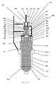
燃料インジェクタ1には、図1に示すように、本発明の好ましい実施例によるバルブニードル制御装置3が設けられている。燃料インジェクタ1は、バルブニードル5がインジェクタノズル本体7内に配置された従来の構成のニードルバルブを含む。
As shown in FIG. 1, the
バルブニードル5は細長く、円形の断面輪郭を有し、下端にバルブ面9を有する。バルブ面9の形状は、ノズル本体7に設けられた弁座11と相補的であり、バルブ面9が弁座11と接触したとき、流体密シールがこれらの間に形成される。
The
バルブニードル5の上端にはガイド面13が設けられている。このガイド面13は、バルブニードル5がノズル本体7に対して摺動できるようにノズル本体7と係合する。バルブニードル5とノズル本体7との間の隙間は、バルブ面9とガイド区分13との間に配置された燃料供給チャンバ15からガイド区分13を横切る加圧燃料の流れを最小にするため、最小にされている。燃料供給チャンバ15は環状であり、高圧燃料ライン17によって燃料が供給される。高圧燃料ライン17は、ノズル本体7内の環状凹所19に燃料を供給する。ガイド区分13の下部分には、截頭円錐形中間スラスト面21aが設けられており、バルブニードル5の下部分には、截頭円錐形近位スラスト面21bが設けられている。燃料供給チャンバ内の加圧燃料は、これらのスラスト面21a及び21bに作用する。
A
バルブニードル5の上端には、円柱状ばねガイド24及びその周囲の環状表面の夫々によって形成された遠位スラスト面23a及び23bが設けられている。これらの遠位スラスト面23a、23bは、バルブニードル制御チャンバ25の下壁を形成する。バルブニードル制御チャンバ25の上壁及び側壁は、ノズル本体7によって形成されている。
Disposed at the upper end of the
バルブニードル制御チャンバ25内には、圧縮コイルばね27が設けられている。圧縮コイルばね27は、遠位スラスト面23b及びバルブニードル制御チャンバ25の上壁28に着座する。
A
バルブニードル制御装置3は、全体に参照番号29を付した円形断面のピストンを含む。このピストン29は、円形断面のピストンチャンバ31内に収容されている。
ピストンチャンバ31は、三つの同心のボアから形成された段状の輪郭を有する。ピストンチャンバ31は、最も小径の上ボア33と、比較的大径の中間ボア34と、最も大径の下ボア35とを含む。上ボア33は、その上端及び下端が開放している。上ボア33の下端は中間ボア34の上端に開放しており、中間ボア34は下ボア35に開放しており、下ボア35の下端には、バルブニードル制御チャンバ25の上壁28の開口部36と連通した開口部が設けられている。
The valve
The
ピストン29は、中間ボア34よりも大径であるが下ボア35よりも小径の円柱状の下バルブ部分37と、上ボア33よりも小径となっている同心で円柱状の中間部分39と、上ボア33よりも僅かに小径となっている同心で円柱状の上ガイド部分41とを含む。上ガイド部分41は、上ボア33よりも僅かに小径である。このようにして、ピストン29がボア33内で案内され、これに対して摺動でき、ガイド部分41を横切る燃料の流れを最小にするようになっている。
The
ピストン29は、その下バルブ部分37の下面には、下スラスト面43が設けられており、下バルブ部分37の上面には、環状中間スラスト面45が設けられており、ガイド部分41の下面には環状第2中間スラスト面47が設けられており、ガイド部分41の上面には上スラスト面49が設けられている。環状の第1中間スラスト面45の面積は、環状の第2中間スラスト面47の面積よりも大きい。
The
ガイド部分41は、上ボア33の外側に、ピストン制御チャンバ51内に延びている。上スラスト面49は、ピストン制御チャンバ51の下壁の一部を形成する。下壁の残りの部分、上壁、及び側壁は、燃料インジェクタ1の本体によって形成される。ピストン制御チャンバ51内には、圧縮コイルばね53が設けられている。圧縮コイルばね53は、スラスト面49及びピストン制御チャンバ51の上壁に着座する。
The
高圧燃料入口ライン55が、ピストンチャンバ31の中間ボア34に連結されている。入口オリフィス58が設けられた燃料入口通路57が、ピストン制御チャンバ51に連結されている。漏洩オリフィス60が設けられた燃料出口通路59が、ピストン制御チャンバ51を、低圧リザーバ即ちドレンに連結している。排出バルブ61が、燃料出口通路59に連結されている。排出バルブ61にもオリフィスが設けられている。しかしながら、排出バルブ61のオリフィスは、漏洩オリフィス60よりも制限が小さい。オリフィス64を備えた燃料移送通路63が、ピストン制御チャンバ51とバルブニードル制御チャンバ25とを連結している。
A high pressure
作動に当たっては、燃料インジェクタ1からの燃料の噴射を行うのが望ましくない場合には、バルブニードル5に作用する下方への正味力により、バルブ面9が弁座11に当たった状態に保持されるように、アクチュエータ(図示せず)の作動により排出バルブ61を閉鎖する。下方への正味力は、バルブニードル5の遠位スラスト面23a、23bに下方に作用する、バルブニードル制御チャンバ25内の高圧燃料からの力と、ばね27が発生する下方へのばね力との組み合わせにより発生する。下方への正味力は、燃料供給チャンバ15内の高圧燃料(高圧燃料ライン17を介して供給された)により発生した、バルブニードル5の中間スラスト面21a及び近位スラスト面21bに作用する上方への力よりも大きい。
In operation, when it is not desirable to inject fuel from the
高圧燃料は、バルブニードル制御チャンバ25に二つの供給源から供給される。第1供給源は、燃料入口通路57から始まる。これは、入口オリフィス58を通過し、ピストン制御チャンバ51を通過し、次いで移送通路63のオリフィス64を介してチャンバ25内に連通する。第2供給源は、高圧燃料入口通路55からであり、ピストンチャンバ31を介する供給源である。
High pressure fuel is supplied to the valve
バルブニードル制御チャンバ25内の燃料の圧力を増大する上で必要な第1の作用は、ソレノイドアクチュエータ(図示せず)を使用して排出バルブ61を閉鎖することによって、ピストン制御チャンバ51からの出口59を閉鎖することである。これにより、燃料入口通路57からピストン制御チャンバ51に供給された燃料が、燃料出口通路59を介して低圧ドレンに出ないようにする。入口通路57からの高圧燃料は、ピストン制御チャンバ51を充填し、かくして、ピストン制御チャンバ51内の燃料圧力を上昇する。更に、高圧燃料は、移送通路63のオリフィス64を介してバルブニードル制御チャンバ25に移送され、かくして、バルブニードル制御チャンバ25内の燃料圧力を上昇する。
The first action required to increase the pressure of fuel in the valve
バルブニードル制御チャンバ25内の燃料の圧力を増大する上で必要な第2の作用は、高圧燃料入口通路55とバルブニードル制御チャンバ25との間の燃料流路を開放することである。これを行うため、ピストン29が下方に移動することにより下バルブ部分37が中間ピストンボア35から離間するように、ピストン29に下方への正味力を加えなければならない。ピストン制御チャンバ51内の燃料の圧力が、所定レベルまで上昇したとき、ピストン29が下方に移動する。その所定レベルとは、加圧燃料によって発生されピストン29の上スラスト面49に作用する力と、ばね53によって加えられた下方への力と、ライン55からの高圧燃料によって発生され、環状第1中間スラスト面45に作用する力との組み合わせが、バルブニードル制御チャンバ25から開口部36を通過する燃料により下スラスト面43に作用する上方への力と、ライン55からの高圧燃料によって発生され、第2中間スラスト面47に作用する力との組み合わせよりも大きい場合である。
A second action required to increase the pressure of the fuel in the valve
ピストン29が下方に移動するとき、下バルブ部分37の上面が下ボア35の上面から離間する。これにより燃料入口通路55とバルブニードル制御チャンバ25との間の燃料流路が開放する。これにより、バルブニードル制御チャンバ25は、燃料入口通路55からの高圧燃料によって急速に充填される。
When the
作動に当たっては、燃料を燃料インジェクタ1から噴射するのが所望である場合には、バルブニードル5に上方への正味力を加えることによって、バルブニードル5を弁座11から持ち上げて離さなければならない。これを行うため、バルブニードル制御チャンバ25内の燃料の圧力を低下しなければならない。
In operation, if it is desired to inject fuel from the
第1工程は、ソレノイドアクチュエータ(図示せず)を使用して排出バルブ61を開放することによって、ピストン制御チャンバ51からの燃料出口通路59を開放する工程である。これにより、ピストン制御チャンバ51内の高圧燃料と、高圧燃料入口通路57及び燃料移送通路63からピストン制御チャンバ51に流入する高圧燃料とを、低圧ドレン又はリザーバに逃がすことができ、かくして、第1工程として、ピストン制御チャンバ51内の燃料圧力を低減することができる。
The first step is a step of opening the
バルブニードル制御チャンバ25の圧力を燃料移送通路63を介して逃がすことにより、バルブニードル制御チャンバ25内の燃料の圧力を低下できる。
更に、ピストン制御チャンバ51の圧力を逃がすと、下スラスト面43に加わる力により、ピストン29が上方に移動するように作用する正味力がピストン29に作用する効果が得られる。これは、開口部36を介して作用するバルブニードル制御チャンバ25内の加圧燃料により生じる、下スラスト面43に作用する力と、燃料入口通路55からの燃料圧力により第2中間スラスト面47に加えられた力とが、燃料入口通路55からの圧力により第1中間スラスト面45に作用する力と、ピストン制御チャンバ51内の燃料の圧力により上スラスト面49に作用する力と、ピストン29に下方に作用するばね53からのばね力とよりも、大きいためである。
By letting the pressure in the valve
Furthermore, when the pressure in the
ピストン29が上方に移動すると、下バルブ部分37の上面がボア35の上面と接触し、かくして、燃料入口通路55とバルブニードル制御チャンバ25との間の流路をなくす。
As the
もはやバルブニードル制御チャンバ25に高圧燃料が燃料入口通路55から供給されないため、また、バルブニードル制御チャンバ25内の燃料が、燃料移送通路63及び出口通路59を介して逃がされるため、バルブニードル制御チャンバ25内の圧力は低下する。この時点で、バルブニードル5に作用する正味力は上方に作用する。これは、ピストン制御チャンバ51内の燃料の圧力及びばね27により遠位スラスト面23a、23bに作用する下方への力が、スラスト面21a、21bに作用する上方への力よりも小さいためである。従って、バルブニードル5は上方へ移動し、噴射オリフィスを開放し、燃料噴射を可能にする。
Since the high pressure fuel is no longer supplied from the
噴射を停止する必要がある場合には、バルブニードル5をノズル本体7に当てた状態にするための上文中に説明した手順を使用する。
ピストン制御チャンバ51への燃料入口通路57と、ピストン制御チャンバから延びる燃料出口通路59及び燃料移送通路63には、オリフィス58、60、64が夫々設けられている。漏洩オリフィス60の目的は、排出バルブ61のバルブ部材のリフトについての許容差の効果を低減することである。排出バルブ部材がその弁座から持ち上げられる距離が、バルブの流れ面積を変化する。漏洩オリフィス60は、その排出バルブ61が開放したとき、排出バルブ61の直下の燃料圧力を低下させる。燃料圧力が低下した場合、流量面積の変化により、バルブを通る流量に及ぼされる効果が小さくなる。これによって、排出バルブ61のリフト許容差に対するシステムの感度が低下する。
When it is necessary to stop the injection, the procedure described above for setting the
In the
排出バルブ61内のオリフィスは、排出バルブ61に作用する圧力のレベルを低下するために設けられている。これは、排出バルブ61がアンバランス型バルブであるためである。即ち、排出バルブ61の一方の側にしか高圧が加わらず(他方の側は低圧リザーバに連結されている)、バルブ61の高圧側の圧力が高ければ高い程、これを閉鎖するのに必要なソレノイドアクチュエータが大型になるためである。ソレノイドアクチュエータは、インジェクタ本体内に装着しなければならないため、その大きさが限られており、かくしてその閉鎖力が限定され、排出バルブ61に加わる圧力をこれに従って選択しなければならない。 The orifice in the discharge valve 61 is provided to reduce the level of pressure acting on the discharge valve 61. This is because the discharge valve 61 is an unbalanced valve. That is, high pressure is only applied to one side of the discharge valve 61 (the other side is connected to a low pressure reservoir), and the higher the pressure on the high pressure side of the valve 61, the more necessary to close it. This is because the solenoid actuator becomes large. Since the solenoid actuator must be mounted in the injector body, its size is limited, thus its closing force is limited and the pressure applied to the discharge valve 61 must be selected accordingly.
ピストン制御チャンバ51への流量を減少するため、入口オリフィス58が、燃料入口通路57に設けられている。制限部58が設けられていない場合には、チャンバ51への流量は、オリフィス60によって制流がなされる燃料出口通路59を通してチャンバ51から逃がすことができる流量よりも大きくなり、その結果、噴射を行うためにバルブニードル5を開放するため、チャンバ51を排出することができなくなる。
An
ニードルバルブの開放中、バルブニードル5が上方に移動するとき、バルブニードル5の移動速度を制御できる手段を設ける必要がある。本発明では、バルブニードル5の移動速度は、バルブニードル制御チャンバ25内の圧縮効果によって制御される。排出バルブ61を開放すると、バルブニードル制御チャンバ25内の圧力が低下し、バルブニードル5は上方へ移動を開始する。バルブニードル制御チャンバ25内の圧力の低下は、燃料移送通路63内のオリフィス64によって制御される。バルブニードル5が上方へ移動するとき、バルブニードル制御チャンバ25の容積が減少する。このことは、このチャンバ内の圧力を上昇する傾向がある。オリフィス64の効果及びバルブニードル制御チャンバ25の容積の減少の効果が、開放中、バルブニードル制御チャンバ25内に均衡した圧力を発生し、これがバルブニードル5の開放速度を制御する。
It is necessary to provide means for controlling the moving speed of the
本発明の第2実施例を図3に示す。この実施例は、第1実施例の全ての特徴を有し(等価の特徴には、先頭に2を付けた同じ参照番号が付してある)、更に、高圧燃料供給ライン217とバルブニードル制御チャンバ225との間に制限部を持つ燃料供給通路270を含む。
A second embodiment of the present invention is shown in FIG. This embodiment has all the features of the first embodiment (equivalent features are given the same reference number with a leading 2), and further includes a high pressure
作動では、第2実施例は、バルブニードル制御チャンバ225が、開口部236及び燃料移送通路263を介して充填されるのに加え、燃料供給通路270からの加圧燃料で充填できるという点で、第1実施例と異なっている。インジェクタの液圧指令を最適化するとき、燃料供給通路270は、最適化を行う上で追加の自由度を提供する。
In operation, the second embodiment is that the valve
本発明の第3実施例を図4に示す。この実施例は、ピストン制御チャンバ351への燃料入口通路がないことを除き、第1実施例の全ての特徴を有する(等価の特徴には、先頭に3を付けた同じ参照番号が付してある)。 A third embodiment of the present invention is shown in FIG. This embodiment has all the features of the first embodiment except that there is no fuel inlet passage to the piston control chamber 351 (equivalent features have the same reference number with a leading 3). is there).
作動では、第3実施例は、ピストン制御チャンバ351が燃料移送通路363を介してしか充填できないという点で、第1実施例と異なっている。インジェクタの液圧指令を最適化するとき、ピストン制御チャンバ351への燃料供給通路がないため、最適化を行う上で自由度の一つがなくされる。
In operation, the third embodiment differs from the first embodiment in that the
本発明の第4実施例を図5に示す。この実施例は、ピストン制御チャンバ451への燃料入口通路がなく、高圧燃料供給ライン417とバルブニードル制御チャンバ425との間に制限部を持つ燃料供給通路470を含むことを除き、第1実施例の全ての特徴を有する(等価の特徴には、先頭に4を付けた同じ参照番号が付してある)。
A fourth embodiment of the present invention is shown in FIG. This embodiment is the first embodiment except that there is no fuel inlet passage to the
作動では、第4実施例は、ピストン制御チャンバ451が燃料移送通路463を介してしか充填できないという点で、第1実施例と異なっている。しかしながら、バルブニードル制御チャンバ425は、燃料供給通路470からの加圧燃料で充填できる。従って、インジェクタの液圧指令を最適化するための自由度が多く維持されている。
In operation, the fourth embodiment differs from the first embodiment in that the
本発明の第5実施例を図6に示す。この実施例は、第1実施例の全ての特徴を有する(等価の特徴には、先頭に5を付けた同じ参照番号が付してある)。しかしながら、制御バルブ装置503はバランス型ピストン装置を有する。バランス型ピストン装置を使用することにより、様々なパラメータの最適化に影響が及ぼされる。これは、アンバランス型ピストンと比較して閉鎖遅延が増大するためである(アンバランス型ピストンでは、ピストンを下方に移動するのに必要な正味力が更に迅速に得られる)。
A fifth embodiment of the present invention is shown in FIG. This embodiment has all the features of the first embodiment (equivalent features are given the same reference number with a leading 5). However, the
1 燃料インジェクタ
3 バルブニードル制御装置
5 バルブニードル
7 インジェクタノズル本体
9 バルブ面
11 弁座
13 ガイド面
15 燃料供給チャンバ
17 高圧燃料ライン
19 環状凹所
21a 中間スラスト面
21b 近位スラスト面
23a、23b 遠位スラスト面
24 円柱状ばねガイド
25 バルブニードル制御チャンバ
27 圧縮コイルばね
29 ピストン
31 ピストンチャンバ
33 上ボア
34 中間ボア
35 下ボア
37 下バルブ部分
39 中間部分
41 上ガイド部分
43 下スラスト面
45 中間スラスト面
47 第2中間スラスト面
49 上スラスト面
51 ピストン制御チャンバ
53 圧縮コイルばね
55 高圧燃料入口ライン
57 燃料入口通路
58 入口オリフィス
59 燃料出口通路
60 漏洩オリフィス
61 排出バルブ
63 燃料移送通路
64 オリフィス
DESCRIPTION OF
Claims (9)
前記燃料インジェクタ(1)は、燃料噴射バルブを備えており、
前記燃料噴射バルブは、使用時に作用する、噴射バルブ部材制御チャンバ(25)内の燃料圧力の作用で閉鎖位置と開放位置との間で移動できる噴射バルブ部材(5)を有しており、
前記燃料インジェクタは、また、
前記噴射バルブ部材制御チャンバ(25)に連結した高圧燃料供給通路(17)と、
低圧リザーバ又はドレンに連結される単一の燃料出口通路(59)と、
前記単一の燃料出口通路(59)に連結された排出バルブ(61)を開閉することにより、前記噴射バルブ部材制御チャンバ(25)と前記低圧リザーバ又はドレンとの間の燃料流路を開閉するように作動できるアクチュエータとを備えており、
前記高圧燃料供給通路(17)に遮断バルブが設けられており、
前記遮断バルブは、遮断バルブ部材(29)を有しており、
前記遮断バルブ部材(29)は、使用時に、前記遮断バルブ部材(29)に作用する遮断バルブ部材制御チャンバ(51)内の燃料圧力の作用で閉鎖位置と開放位置との間で移動でき、
前記遮断バルブ部材制御チャンバ(51)は、前記排出バルブ(61)を介して前記低圧リザーバ又はドレンに連結でき、
燃料移送通路(63)が、前記噴射バルブ部材制御チャンバ(25)と前記低圧リザーバ又はドレンとの間に設けられている、燃料インジェクタ(1)。 A fuel injector (1) for a compression ignition internal combustion engine,
The fuel injector (1) includes a fuel injection valve,
The fuel injection valve has an injection valve member (5) that can be moved between a closed position and an open position by the action of fuel pressure in the injection valve member control chamber (25) that acts during use.
The fuel injector also has
A high pressure fuel supply passage (17) connected to the injection valve member control chamber (25);
A single fuel outlet passage (59) connected to the low pressure reservoir or drain;
A fuel flow path between the injection valve member control chamber (25) and the low pressure reservoir or drain is opened and closed by opening and closing a discharge valve (61) connected to the single fuel outlet passage (59). And an actuator that can operate as follows :
A shutoff valve is provided in the high pressure fuel supply passage (17),
The shut-off valve has a shut-off valve member (29),
The shutoff valve member (29) can be moved between a closed position and an open position by the action of fuel pressure in the shutoff valve member control chamber (51) acting on the shutoff valve member (29) in use.
The shutoff valve member control chamber (51) can be connected to the low pressure reservoir or drain via the discharge valve (61),
A fuel injector (1) in which a fuel transfer passage (63) is provided between the injection valve member control chamber (25) and the low pressure reservoir or drain.
前記遮断バルブは、遮断バルブ本体を含み、
前記遮断バルブ本体内で、ピストンの形態の前記遮断バルブ部材(29)が、ピストンチャンバ(31)内で摺動可能に移動でき、
前記バルブ本体は、第1端部が前記遮断バルブ部材制御チャンバ(51)に流体的に連結されており、
第2端部が、これらの二つの端部間の中間燃料チャンバ(34)のところで前記高圧燃料移送通路(17)に流体的に連結されており、
前記バルブ本体には、前記中間チャンバ(34)と前記第2端部との間に弁座が設けられており、
前記遮断バルブ部材(29)には、前記遮断バルブの閉鎖時に前記弁座と係合して前記高圧燃料移送通路(55)内に流体密閉鎖体を形成できるバルブ面が設けられている、燃料インジェクタ(1)。 The fuel injector (1) according to claim 1,
The shut-off valve includes a shut-off valve body,
Within the shut-off valve body, the shut-off valve member (29) in the form of a piston can move slidably within the piston chamber (31),
The valve body has a first end fluidly connected to the shut-off valve member control chamber (51),
A second end is fluidly coupled to the high pressure fuel transfer passageway (17) at an intermediate fuel chamber (34) between the two ends;
The valve body is provided with a valve seat between the intermediate chamber (34) and the second end,
Wherein the shut-off valve member (29), the valve seat and Luba Lube surface can form a fluid tight closure body engages the high pressure fuel transfer passage (55) in at closing of the shut-off valve is provided The fuel injector (1).
前記遮断バルブ部材は、
前記バルブ本体の前記第1端部と近接した、前記遮断バルブ部材の第1端部に、前記遮断バルブ部材制御チャンバ(51)と流体連通した第1スラスト面(49)を有し、
前記バルブ本体の前記第2端部と近接した、前記遮断バルブ部材の第2端部に、前記噴射バルブ部材制御チャンバ(25)と流体連通した第2スラスト面(43)を有し、
これらの二つの端部間に、前記遮断バルブ部材(29)の前記第1端部と近接した第1中間スラスト面(47)を有し、
前記遮断バルブ部材(29)の前記第2端部と近接した第2中間スラスト面(45)を有し、
前記第1中間スラスト面(47)及び前記第2中間スラスト面(45)は、前記中間燃料チャンバ(34)と流体連通している、燃料インジェクタ(1)。 The fuel injector (1) according to claim 2,
The shut-off valve member is
A first thrust surface (49) in fluid communication with the shut-off valve member control chamber (51) at a first end of the shut-off valve member proximate to the first end of the valve body;
A second thrust surface (43) in fluid communication with the injection valve member control chamber (25) at a second end of the shutoff valve member proximate to the second end of the valve body;
Between these two ends, there is a first intermediate thrust surface (47) proximate to the first end of the shutoff valve member (29),
A second intermediate thrust surface (45) proximate to the second end of the shutoff valve member (29);
The fuel injector (1), wherein the first intermediate thrust surface (47) and the second intermediate thrust surface (45) are in fluid communication with the intermediate fuel chamber (34).
前記遮断バルブ部材(29)はアンバランス型である、燃料インジェクタ(1)。 The fuel injector (1) according to claim 1, 2, or 3,
The shutoff valve member (29) is an unbalanced fuel injector (1).
前記遮断バルブ部材(29)はバランス型である、燃料インジェクタ(1)。 The fuel injector (1) according to claim 1, 2, or 3,
The shutoff valve member (29) is a balance type fuel injector (1).
弾性エレメント(53)が、前記遮断バルブ部材(29)を、前記遮断バルブ部材が開放する位置に押圧する、燃料インジェクタ(1)。 The fuel injector (1) according to any one of claims 1 to 5,
A fuel injector (1), wherein an elastic element (53) presses the shut-off valve member (29) to a position where the shut-off valve member is opened.
制限部(64)が前記燃料移送通路(63)に設けられている、燃料インジェクタ(1)。 The fuel injector (1) according to any one of claims 1 to 6,
A fuel injector (1) in which a restriction (64) is provided in the fuel transfer passage (63).
前記高圧燃料供給通路(17)と前記遮断バルブ部材制御チャンバ(51)との間に連結された、制限部を持つ燃料供給通路(57)を備えた、燃料インジェクタ(1)。 The fuel injector (1) according to any one of the preceding claims, further comprising:
A fuel injector (1) comprising a fuel supply passage (57) having a restricting portion connected between the high-pressure fuel supply passage (17) and the shutoff valve member control chamber (51).
高圧燃料供給通路(217)と前記噴射バルブ部材制御チャンバ(225)との間に直接的に連結された、制限部を持つ燃料供給通路(270)を備えた、燃料インジェクタ(201)。 The fuel injector (201) according to any one of the preceding claims, further comprising:
A fuel injector (201) comprising a fuel supply passage (270) having a restricting portion connected directly between a high-pressure fuel supply passage (217) and the injection valve member control chamber (225).
Applications Claiming Priority (3)
| Application Number | Priority Date | Filing Date | Title |
|---|---|---|---|
| EP08101850.9 | 2008-02-21 | ||
| EP08101850.9A EP2093410B1 (en) | 2008-02-21 | 2008-02-21 | A fuel injector with an improved valve control arrangement |
| PCT/EP2009/052132 WO2009103819A1 (en) | 2008-02-21 | 2009-02-23 | A fuel injector with an improved valve control arrangement |
Publications (2)
| Publication Number | Publication Date |
|---|---|
| JP2011512486A JP2011512486A (en) | 2011-04-21 |
| JP5236018B2 true JP5236018B2 (en) | 2013-07-17 |
Family
ID=39672145
Family Applications (1)
| Application Number | Title | Priority Date | Filing Date |
|---|---|---|---|
| JP2010547195A Active JP5236018B2 (en) | 2008-02-21 | 2009-02-23 | Fuel injector with improved valve control |
Country Status (8)
| Country | Link |
|---|---|
| US (1) | US8708249B2 (en) |
| EP (2) | EP2743490A1 (en) |
| JP (1) | JP5236018B2 (en) |
| CN (2) | CN103644055A (en) |
| ES (1) | ES2464451T3 (en) |
| PL (1) | PL2093410T3 (en) |
| PT (1) | PT2093410E (en) |
| WO (1) | WO2009103819A1 (en) |
Families Citing this family (10)
| Publication number | Priority date | Publication date | Assignee | Title |
|---|---|---|---|---|
| DE102012220025A1 (en) * | 2012-06-29 | 2014-01-02 | Robert Bosch Gmbh | Fuel injection valve for internal combustion engines |
| EP2829718B1 (en) * | 2013-07-22 | 2016-07-13 | Delphi International Operations Luxembourg S.à r.l. | Injector Arrangement |
| EP2857670B1 (en) * | 2013-10-04 | 2018-12-12 | Continental Automotive GmbH | Fuel injector |
| US9897033B2 (en) * | 2014-05-15 | 2018-02-20 | Cummins Inc. | High pressure, high speed regulating switch valve |
| GB201414669D0 (en) * | 2014-08-19 | 2014-10-01 | Delphi International Operations Luxembourg S.�.R.L. | Control valve arrangement |
| US10544769B2 (en) * | 2016-10-07 | 2020-01-28 | Caterpillar Inc. | Stand-alone common rail capable injector system |
| DE102017002366A1 (en) | 2017-03-10 | 2018-09-13 | Liebherr-Components Deggendorf Gmbh | Fuel injection valve |
| GB201713163D0 (en) * | 2017-08-16 | 2017-09-27 | Univ Oxford Innovation Ltd | HPV vaccine |
| DE102017220328A1 (en) * | 2017-11-15 | 2019-05-16 | Robert Bosch Gmbh | Vibration damping arrangement for injection systems of motor vehicles, in particular for fuel injection systems, and injection system with such a vibration damping arrangement |
| WO2021001020A1 (en) * | 2019-07-02 | 2021-01-07 | Volvo Truck Corporation | A flow control system |
Family Cites Families (15)
| Publication number | Priority date | Publication date | Assignee | Title |
|---|---|---|---|---|
| FR2756595B1 (en) * | 1996-12-02 | 1999-02-12 | Froment Jean Louis | OPENING SLOWDOWN AND LEAKAGE REDUCTION DEVICE FOR CONSTANT PRESSURE INJECTION SYSTEMS USED ON DIESEL ENGINES |
| WO2000055490A1 (en) | 1999-03-18 | 2000-09-21 | Delphi Technologies Inc. | Fuel injector |
| JP3578105B2 (en) * | 2001-04-12 | 2004-10-20 | トヨタ自動車株式会社 | Fuel injection device |
| US6655602B2 (en) * | 2001-09-24 | 2003-12-02 | Caterpillar Inc | Fuel injector having a hydraulically actuated control valve and hydraulic system using same |
| US6824081B2 (en) * | 2002-06-28 | 2004-11-30 | Cummins Inc. | Needle controlled fuel injector with two control valves |
| US6880766B2 (en) * | 2003-02-28 | 2005-04-19 | Caterpillar Inc | Leak arrest volume for reducing component separation and fuel injector using same |
| JP4023804B2 (en) * | 2003-09-08 | 2007-12-19 | 株式会社日本自動車部品総合研究所 | Injector for internal combustion engine |
| JP2005207323A (en) * | 2004-01-22 | 2005-08-04 | Denso Corp | Fuel injection device |
| JP4305394B2 (en) * | 2005-01-25 | 2009-07-29 | 株式会社デンソー | Fuel injection device for internal combustion engine |
| US7334741B2 (en) * | 2005-01-28 | 2008-02-26 | Cummins Inc. | Fuel injector with injection rate control |
| JP4380549B2 (en) * | 2005-01-31 | 2009-12-09 | 株式会社デンソー | Fuel injection valve |
| JP4483828B2 (en) * | 2005-09-15 | 2010-06-16 | 株式会社デンソー | Fuel injection valve |
| JP4459183B2 (en) * | 2006-03-16 | 2010-04-28 | 株式会社デンソー | Injector |
| JP2008008163A (en) | 2006-06-27 | 2008-01-17 | Denso Corp | Fuel injection valve |
| JP2008202417A (en) * | 2007-02-16 | 2008-09-04 | Toyota Motor Corp | Fuel injection control device of internal combustion engine |
-
2008
- 2008-02-21 EP EP14152229.2A patent/EP2743490A1/en not_active Withdrawn
- 2008-02-21 ES ES08101850.9T patent/ES2464451T3/en active Active
- 2008-02-21 PT PT81018509T patent/PT2093410E/en unknown
- 2008-02-21 EP EP08101850.9A patent/EP2093410B1/en active Active
- 2008-02-21 PL PL08101850T patent/PL2093410T3/en unknown
-
2009
- 2009-02-23 WO PCT/EP2009/052132 patent/WO2009103819A1/en active Application Filing
- 2009-02-23 JP JP2010547195A patent/JP5236018B2/en active Active
- 2009-02-23 US US12/918,135 patent/US8708249B2/en active Active
- 2009-02-23 CN CN201310660940.9A patent/CN103644055A/en active Pending
- 2009-02-23 CN CN200980114144.7A patent/CN102066740B/en active Active
Also Published As
| Publication number | Publication date |
|---|---|
| EP2743490A1 (en) | 2014-06-18 |
| CN103644055A (en) | 2014-03-19 |
| EP2093410B1 (en) | 2014-04-09 |
| US20110017844A1 (en) | 2011-01-27 |
| CN102066740A (en) | 2011-05-18 |
| PL2093410T3 (en) | 2014-07-31 |
| PT2093410E (en) | 2014-05-26 |
| EP2093410A1 (en) | 2009-08-26 |
| ES2464451T3 (en) | 2014-06-02 |
| US8708249B2 (en) | 2014-04-29 |
| CN102066740B (en) | 2014-01-08 |
| JP2011512486A (en) | 2011-04-21 |
| WO2009103819A1 (en) | 2009-08-27 |
Similar Documents
| Publication | Publication Date | Title |
|---|---|---|
| JP5236018B2 (en) | Fuel injector with improved valve control | |
| US8662411B2 (en) | Fuel injection valve for internal combustion engines | |
| JP5680631B2 (en) | Fuel injector | |
| JP2008309015A (en) | Fuel injection control device for internal combustion engine | |
| JP2015519515A (en) | Fuel injector | |
| WO2006038636A1 (en) | Fuel injection device | |
| JP2005526211A (en) | Fuel injection valve for internal combustion engine | |
| JP2006307860A (en) | Injection nozzle | |
| JP4075894B2 (en) | Fuel injection device | |
| JP2006512533A (en) | Fuel injection valve with two coaxial valve needles | |
| US6928986B2 (en) | Fuel injector with piezoelectric actuator and method of use | |
| GB2424451A (en) | Fuel injection valve with concentric inner and outer valve needles | |
| JP2004502076A (en) | Pressure-controlled double-switching high-pressure injector | |
| KR20020063100A (en) | Fuel injector assembly and internal combustion engine including same | |
| EP2829718B1 (en) | Injector Arrangement | |
| KR102244948B1 (en) | Fuel injection nozzle | |
| JP4329704B2 (en) | Fuel injection device | |
| JP2004512464A (en) | Injector with double slider, stroke and pressure controlled | |
| JP2004503710A (en) | Fuel injection device used for internal combustion engine | |
| KR101623679B1 (en) | Hydraulic-drive fuel injection device and internal combustion engine | |
| JP4412384B2 (en) | Fuel injection device | |
| JP4305353B2 (en) | Fuel injection device | |
| JP2007154896A (en) | Injector for fuel injection device |
Legal Events
| Date | Code | Title | Description |
|---|---|---|---|
| A131 | Notification of reasons for refusal |
Free format text: JAPANESE INTERMEDIATE CODE: A131 Effective date: 20120517 |
|
| A977 | Report on retrieval |
Free format text: JAPANESE INTERMEDIATE CODE: A971007 Effective date: 20120524 |
|
| A601 | Written request for extension of time |
Free format text: JAPANESE INTERMEDIATE CODE: A601 Effective date: 20120816 |
|
| A602 | Written permission of extension of time |
Free format text: JAPANESE INTERMEDIATE CODE: A602 Effective date: 20120823 |
|
| A521 | Request for written amendment filed |
Free format text: JAPANESE INTERMEDIATE CODE: A523 Effective date: 20121119 |
|
| TRDD | Decision of grant or rejection written | ||
| A01 | Written decision to grant a patent or to grant a registration (utility model) |
Free format text: JAPANESE INTERMEDIATE CODE: A01 Effective date: 20130225 |
|
| A61 | First payment of annual fees (during grant procedure) |
Free format text: JAPANESE INTERMEDIATE CODE: A61 Effective date: 20130326 |
|
| R150 | Certificate of patent or registration of utility model |
Free format text: JAPANESE INTERMEDIATE CODE: R150 Ref document number: 5236018 Country of ref document: JP Free format text: JAPANESE INTERMEDIATE CODE: R150 |
|
| FPAY | Renewal fee payment (event date is renewal date of database) |
Free format text: PAYMENT UNTIL: 20160405 Year of fee payment: 3 |
|
| S111 | Request for change of ownership or part of ownership |
Free format text: JAPANESE INTERMEDIATE CODE: R313111 |
|
| R350 | Written notification of registration of transfer |
Free format text: JAPANESE INTERMEDIATE CODE: R350 |
|
| R250 | Receipt of annual fees |
Free format text: JAPANESE INTERMEDIATE CODE: R250 |
|
| R250 | Receipt of annual fees |
Free format text: JAPANESE INTERMEDIATE CODE: R250 |
|
| R250 | Receipt of annual fees |
Free format text: JAPANESE INTERMEDIATE CODE: R250 |
|
| R250 | Receipt of annual fees |
Free format text: JAPANESE INTERMEDIATE CODE: R250 |
|
| R250 | Receipt of annual fees |
Free format text: JAPANESE INTERMEDIATE CODE: R250 |