JP2009050099A - Rotor core, permanent magnet rotor, and permanent magnet synchronous electric rotating machine - Google Patents
Rotor core, permanent magnet rotor, and permanent magnet synchronous electric rotating machine Download PDFInfo
- Publication number
- JP2009050099A JP2009050099A JP2007214585A JP2007214585A JP2009050099A JP 2009050099 A JP2009050099 A JP 2009050099A JP 2007214585 A JP2007214585 A JP 2007214585A JP 2007214585 A JP2007214585 A JP 2007214585A JP 2009050099 A JP2009050099 A JP 2009050099A
- Authority
- JP
- Japan
- Prior art keywords
- permanent magnet
- rotor
- rotor core
- rotation axis
- rectangular parallelepiped
- Prior art date
- Legal status (The legal status is an assumption and is not a legal conclusion. Google has not performed a legal analysis and makes no representation as to the accuracy of the status listed.)
- Pending
Links
Images


Abstract
Description
本発明は内部に界磁用の永久磁石を配置するための回転子コア、永久磁石回転子および永久磁石形同期回転電機に関する。 The present invention relates to a rotor core, a permanent magnet rotor, and a permanent magnet type synchronous rotating electric machine for arranging a field permanent magnet therein.
本発明は同期電動機および同期発電機に適用できるものであるが、以下では同期電動機の例で説明する。
従来、永久磁石形電動機の回転子コアに設けた内磁形の永久磁石形電動機として、回転子に設けた永久磁石挿入溝に永久磁石を挿入した構造のものがある。
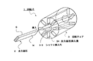
図7は第1従来例を示す内磁形の永久磁石形電動機に用いられる回転子の概略斜視図を示している。図において、1は回転子、2は直方形の永久磁石、3は回転子コア、4はシャフトである。永久磁石2は回転子コア3の端面31から他端の端面32に向けて開けられた永久磁石挿入溝34に挿入されている。
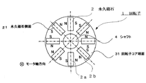
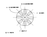
図8は図7の回転子コアにおける永久磁石の配置を示す正面図である。図において、隣り合う永久磁石2aと2bはその同極が対向するように配置され、回転子1の半径方向に向けて放射状に配置されている。モータ軸方向を回転子端面31から32(図7)に向かう方向とすると、永久磁石2はモータ軸方向に対し平行(図で紙面に垂直方向)に配置されている。
このような回転子1にスキューを形成する方法として、回転子1をモータ軸方向に分割し、分割した回転子を一定角度づつずらして階段状にしたものがある(例えば、特許文献1参照)。
図9は第2従来例を示す永久磁石形電動機に用いられる回転子の概略斜視図である。
図において、1は回転子、2は永久磁石、3は回転子コアである。11〜13はモータ軸方向に複数に分割した回転子コアと永久磁石を配置した分割回転子であり、回転子1は分割回転子11〜13を所定の角度でずらせて組み合わせることにより構成されている。
第1従来例は直方体の永久磁石を細長い溝に挿入して成る回転子であったが、第3従来例として、永久磁石挿入穴に樹脂製永久磁石を射出成形することによりスキューを構成したものがある。
図10は第3従来例を示す永久磁石形電動機に用いられる回転子の概略斜視である。図において、1は回転子、2は永久磁石、3は回転子コアである。回転子コア3には永久磁石挿入溝34が設けられており、樹脂製の永久磁石2を永久磁石挿入溝34に射出成形することによって形成している。
図11は図10の回転子コア端面における永久磁石の配置を示す正面図であり、回転子コア端面31,32をモータ軸方向に見た図である。21は回転子コア端面31における永久磁石2の端面(実線)であり、22は回転子コア端面32における永久磁石2の端面(点線)である。永久磁石2は回転子コアに対し放射状に配置され、かつ回転子コア端面31から32に向けて連続的なスキューを構成しているのが判る。
2. Description of the Related Art Conventionally, there is a structure in which a permanent magnet is inserted into a permanent magnet insertion groove provided in a rotor as an inner magnet type permanent magnet motor provided in a rotor core of a permanent magnet type motor.
FIG. 7 is a schematic perspective view of a rotor used in an internal magnet type permanent magnet motor showing a first conventional example. In the figure, 1 is a rotor, 2 is a rectangular permanent magnet, 3 is a rotor core, and 4 is a shaft. The
FIG. 8 is a front view showing the arrangement of permanent magnets in the rotor core of FIG. In the figure, adjacent
As a method of forming a skew in such a
FIG. 9 is a schematic perspective view of a rotor used in a permanent magnet type electric motor showing a second conventional example.
In the figure, 1 is a rotor, 2 is a permanent magnet, and 3 is a rotor core. Reference numerals 11 to 13 denote divided rotors in which a rotor core and permanent magnets divided into a plurality of parts in the motor shaft direction are arranged, and the
The first conventional example is a rotor formed by inserting a rectangular parallelepiped permanent magnet into an elongated groove. As a third conventional example, a skew is formed by injection molding a resin permanent magnet into a permanent magnet insertion hole. There is.
FIG. 10 is a schematic perspective view of a rotor used in a permanent magnet type motor showing a third conventional example. In the figure, 1 is a rotor, 2 is a permanent magnet, and 3 is a rotor core. The
FIG. 11 is a front view showing the arrangement of the permanent magnets on the end surface of the rotor core of FIG. 10, and is a view of the
従来の内磁形の永久磁石モータでは、回転子と固定子間にコギングトルクが発生する。コギングトルクを低減するためには回転子にスキューを施す方法が有効である。
第2従来例に示すごとく、回転子をモータ軸方向に分割し、分割した回転子を一定角度づつずらし階段状にしてスキューを構成する場合では、コギングトルクが発生しなくなるものの、回転子がモータ軸方向に分割されているため、永久磁石の挿入および組み立て工数が増加するという問題があった。
また、第3従来例に示すごとく、射出成形で作成された樹脂製の永久磁石を用いてスキューを構成する場合、樹脂製の永久磁石は永久磁石としての性能が低いため、永久磁石の磁束密度が低くなり、モータの性能が低下するという問題があった。
また、樹脂製の永久磁石は成形後に着磁を行う必要があるが、永久磁石が軸方向に連続的にねじれているため、N・SあるいはS・Nの極性を正確にかつ十分に着磁することが難しいという問題があった。
本発明はこのような問題点に鑑みてなされたものであり、スキューによる磁束密度の低下による回転電機の性能低下を抑制し、製作が容易な回転子コア、永久磁石回転子および永久磁石形同期回転電機を提供することを目的とする。
In a conventional inner magnet type permanent magnet motor, cogging torque is generated between the rotor and the stator. In order to reduce the cogging torque, a method of skewing the rotor is effective.
As shown in the second conventional example, when the rotor is divided in the motor axis direction and the divided rotor is shifted by a certain angle to form a skew, the cogging torque is not generated, but the rotor is the motor. Since it is divided in the axial direction, there is a problem in that the number of man-hours for inserting and assembling a permanent magnet increases.
In addition, as shown in the third conventional example, when a skew is formed using a resin permanent magnet created by injection molding, the resin permanent magnet has a low performance as a permanent magnet. There is a problem that the motor performance decreases.
In addition, resin permanent magnets need to be magnetized after molding, but the permanent magnets are twisted continuously in the axial direction, so the polarity of N · S or S · N is accurately and sufficiently magnetized. There was a problem that it was difficult to do.
The present invention has been made in view of such problems, and suppresses the performance deterioration of the rotating electrical machine due to the decrease of the magnetic flux density due to the skew, and the rotor core, the permanent magnet rotor, and the permanent magnet type synchronization that are easy to manufacture. An object is to provide a rotating electrical machine.
上記問題を解決するため、本発明は、次のように構成したのである。
請求項1記載の回転子コアの発明は、直方体の永久磁石を挿入収納するための直方体状の挿入溝が回転軸方向の一端から他端に向けて貫通してなり、かつ前記挿入溝が複数個放射状に形成された回転子コアにおいて、前記直方体状の挿入溝が前記回転軸方向に対して斜めに形成されたことを特徴としている。
請求項2記載の発明は、請求項1記載の回転子コアにおいて、前記回転軸方向に対して斜めに形成された前記挿入溝がその挿入溝の回転軸方向中央で前記回転軸を横切っていることを特徴としている。
請求項3記載の回転子コアの発明は、直方体の永久磁石を挿入収納するための直方体状の挿入溝が回転軸方向の一端から他端に向けて貫通してなり、かつ前記挿入溝が複数個放射状に形成された回転子コアにおいて、前記挿入溝が前記回転子コアの両端から中間点に向けて回転軸方向に対して斜めに形成されかつ前記中間点で互いに貫通していることを特徴としている。
請求項4記載の発明は、請求項3記載の回転子コアにおいて、前記両端から前記中間点まで回転軸方向に対して斜めに形成された前記各挿入溝がそれぞれ前記各挿入溝の回転軸方向の中央で前記回転軸を横切っていることを特徴としている。
請求項5記載の発明は、請求項1〜4のいずれか1項記載の回転子コアにおいて、前記回転子コアが圧粉磁性体で形成されることを特徴としている。
請求項6記載の永久磁石回転子の発明は、請求項1または2記載の回転子コアと、前記回転子コアの前記複数の挿入溝にそれぞれ挿入された直方体の永久磁石と、を備えた永久磁石回転子において、前記直方体の永久磁石が、隣り合う同士の極性が互いに同極となるように対向配置されたことを特徴としている。
請求項7記載の永久磁石回転子の発明は、請求項3または4記載の回転子コアと、前記回転子コアの前記複数の挿入溝にそれぞれ挿入された直方体の永久磁石と、を備えた永久磁石回転子において、前記直方体の永久磁石が、隣り合う同士の極性が互いに同極となるように対向配置されたことを特徴としている。
請求項8記載の永久磁石形同期回転電機の発明は、永久磁石回転子と、前記永久磁石回転子と空隙を介して対向配置した固定子とを有し、前記永久磁石回転子と前記固定子が相対的に回転可能となるように支持されており、かつ前記固定子が固定子コアと多相の電機子コイルを備えてなる永久磁石形同期回転電機において、前記永久磁石回転子が請求項6または7記載の永久磁石回転子であることを特徴としている。
In order to solve the above problem, the present invention is configured as follows.
According to the first aspect of the rotor core, a rectangular parallelepiped insertion groove for inserting and storing a rectangular parallelepiped permanent magnet penetrates from one end to the other end in the rotation axis direction, and a plurality of the insertion grooves are provided. In the rotor core formed radially, the rectangular parallelepiped insertion groove is formed obliquely with respect to the rotation axis direction.
According to a second aspect of the present invention, in the rotor core according to the first aspect, the insertion groove formed obliquely with respect to the rotation axis direction crosses the rotation axis at the center of the insertion groove in the rotation axis direction. It is characterized by that.
According to a third aspect of the present invention, a rectangular parallelepiped insertion groove for inserting and storing a rectangular parallelepiped permanent magnet penetrates from one end to the other end in the direction of the rotation axis, and a plurality of the insertion grooves are provided. In the rotor core formed radially, the insertion grooves are formed obliquely with respect to the rotation axis direction from both ends of the rotor core toward the intermediate point and penetrate each other at the intermediate point. It is said.
According to a fourth aspect of the present invention, in the rotor core according to the third aspect, the insertion grooves formed obliquely with respect to the rotation axis direction from the both ends to the intermediate point are respectively in the rotation axis direction of the insertion grooves. It is characterized by crossing the rotation axis at the center.
According to a fifth aspect of the present invention, in the rotor core according to any one of the first to fourth aspects, the rotor core is formed of a dust magnetic material.
A permanent magnet rotor according to a sixth aspect of the present invention is a permanent magnet comprising the rotor core according to the first or second aspect, and a rectangular parallelepiped permanent magnet inserted into each of the plurality of insertion grooves of the rotor core. The magnet rotor is characterized in that the rectangular parallelepiped permanent magnets are arranged to face each other so that adjacent polarities are the same.
A permanent magnet rotor according to a seventh aspect of the present invention is a permanent magnet comprising the rotor core according to the third or fourth aspect, and a rectangular parallelepiped permanent magnet inserted into each of the plurality of insertion grooves of the rotor core. The magnet rotor is characterized in that the rectangular parallelepiped permanent magnets are arranged to face each other so that adjacent polarities are the same.
The invention of a permanent magnet type synchronous rotating electrical machine according to claim 8 includes a permanent magnet rotor and a stator that is arranged to face the permanent magnet rotor with a gap therebetween, and the permanent magnet rotor and the stator. In a permanent magnet type synchronous rotating electric machine in which the stator includes a stator core and a multi-phase armature coil. It is a permanent magnet rotor described in 6 or 7.
請求項1記載の発明によると、永久磁石の挿入および組み立て工数が増加することなくコギングが低減できる回転子コアが得られる。
請求項2記載の発明によると、永久磁石の配置を回転子のコア両端で対称となるので、コギングトルクを低減することができるとともに、モータ軸方向のトルクや吸引力のアンバランスを低減できる回転子コアが得られる。
請求項3記載の発明によると、永久磁石の挿入および組み立て工数が増加することなくコギングが低減できる回転子コアが得られる。
請求項4記載の発明によると、永久磁石の配置を回転子のコア両端で対称となるので、コギングトルクを低減することができるとともに、モータ軸方向のトルクや吸引力のアンバランスを低減できる回転子コアが得られる。
請求項5記載の発明によると、回転子コアを圧粉磁性体で形成したので、永久磁石の挿入溝をプレス成形などにより容易に形成することができる。
請求項6記載の発明によると、直方体の永久磁石をモータ軸方向に斜めに配置することによりスキューを形成したので永久磁石の挿入および組み立て工数が増加することなくコギングが低減できる。また、永久磁石の形状を直方体としているので、着磁も容易に行うことができる。
請求項7記載の発明によると、挿入溝が回転子コアの両端から中間点に向けて回転軸方向に対して斜めに形成されかつ中間点で互いに貫通しているので、この挿入溝にそれぞれ永久磁石を挿入するとモータ軸方向に対してV字形に配置することになり、スキューを形成し、永久磁石の挿入および組み立て工数が増加することなくコギングが低減できる。また、永久磁石の形状を直方体としているので、着磁も容易に行うことができる。
請求項8記載の発明によると、請求項6または7記載の回転子を使用しているのでコギングトルクを低減した回転電機を得ることができる。
According to the first aspect of the present invention, a rotor core that can reduce cogging without increasing the number of man-hours for inserting and assembling a permanent magnet can be obtained.
According to the second aspect of the present invention, since the permanent magnets are arranged symmetrically at both ends of the rotor core, the cogging torque can be reduced and the rotation capable of reducing the torque in the motor shaft direction and the unbalance of the attractive force. Child core is obtained.
According to the invention described in
According to the fourth aspect of the invention, since the permanent magnets are arranged symmetrically at both ends of the rotor core, the cogging torque can be reduced, and the rotation capable of reducing the torque in the motor shaft direction and the unbalance of the attractive force can be reduced. Child core is obtained.
According to the fifth aspect of the present invention, since the rotor core is formed of the dust magnetic material, the insertion groove of the permanent magnet can be easily formed by press molding or the like.
According to the invention described in claim 6, since the skew is formed by arranging the rectangular parallelepiped permanent magnets obliquely in the motor axial direction, cogging can be reduced without increasing the number of man-hours for inserting and assembling the permanent magnets. Further, since the shape of the permanent magnet is a rectangular parallelepiped, magnetization can be easily performed.
According to the seventh aspect of the present invention, the insertion grooves are formed obliquely with respect to the rotation axis direction from both ends of the rotor core toward the intermediate point and penetrate each other at the intermediate point. When the magnet is inserted, it is arranged in a V shape with respect to the motor axial direction, and a skew is formed, so that cogging can be reduced without increasing the number of man-hours for inserting and assembling the permanent magnet. Further, since the shape of the permanent magnet is a rectangular parallelepiped, magnetization can be easily performed.
According to the invention described in claim 8, since the rotor according to claim 6 or 7 is used, a rotating electrical machine with reduced cogging torque can be obtained.
以下、本発明の実施の形態について図を参照して説明する。 Hereinafter, embodiments of the present invention will be described with reference to the drawings.
図1は本発明の第1実施例に係る永久磁石回転子の概略斜視図を示している。
図において、1は回転子、2は永久磁石、3は回転子コア、4はシャフトである。回転子コア3は積層コアで構成されており、永久磁石2を挿入するための溝34が軸方向に対して斜めに設けられている。シャフト4は回転子コア3の中央中空部に挿入され、焼きばめなどの手段により回転子コア3と連結されている。
永久磁石2の形状は直方体であり、希土類系の焼結磁石を用いている。
図2は第1実施例の永久磁石回転子のコアの溝への永久磁石の挿入を模式的に示した図である。図2に示すように永久磁石2はあらかじめN・Sの着磁を行った後、回転子コア3の永久磁石挿入溝34の中に挿入される。
本発明が従来技術と異なる部分は、直方体の永久磁石を回転子軸方向に対し斜めに配置している点である。
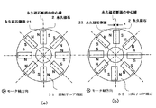
図3は第1実施例の永久磁石の配置を示す図で、(a)は回転子コアの一端面における永久磁石の配置関係を示した正面図、(b)は回転子コアの他端面における永久磁石の配置関係を示した正面図である。
21,22は回転子コア端面31,32(図1参照)における永久磁石2の側面であり、本実施例では、回転子コア端面31では永久磁石側面21の中心線と回転子コアの半径方向の中心軸が一致するように放射状に配置し、回転子コア端面32では永久磁石側面22の中心線が回転子の半径方向の中心軸から所定の距離g離れるように永久磁石2を配置している。
このように永久磁石2を斜めに挿入することでスキューを構成できるので、コギングを低減することができる。
また、直方体の永久磁石2を用いているので着磁が容易であり、かつ高性能の希土類磁石を適用することができるため、この回転子を使用したモータはそのモータの特性を向上させることができる。
また、永久磁石2の形状が直方体であるため、永久磁石2の溝34への挿入も容易であり、工数増加を抑えられる。
FIG. 1 is a schematic perspective view of a permanent magnet rotor according to a first embodiment of the present invention.
In the figure, 1 is a rotor, 2 is a permanent magnet, 3 is a rotor core, and 4 is a shaft. The
The shape of the
FIG. 2 is a diagram schematically showing the insertion of the permanent magnet into the groove of the core of the permanent magnet rotor of the first embodiment. As shown in FIG. 2, the
The present invention is different from the prior art in that a rectangular parallelepiped permanent magnet is disposed obliquely with respect to the rotor axial direction.
3A and 3B are diagrams showing the arrangement of the permanent magnets according to the first embodiment. FIG. 3A is a front view showing the arrangement relationship of the permanent magnets on one end face of the rotor core, and FIG. 3B is the other end face of the rotor core. It is the front view which showed the arrangement | positioning relationship of the permanent magnet.
21 and 22 are side surfaces of the
Since the skew can be configured by inserting the
In addition, since the rectangular
Moreover, since the shape of the
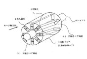
図4は本発明の第2実施例を示す永久磁石回転子の斜視図である。
図において、回転子コア3に設けられた永久磁石挿入溝34を回転子コアの両端31、32から中間点に向けて回転軸方向に対して斜めに形成し、かつ中間点で互いに貫通させて、全体でモータ軸方向に対しV字になるよう構成している。
このように構成することで、永久磁石2を回転子コア3の両端部から挿入するので挿入抵抗が図1と比べて半分になり挿入し易くなる。また、V字形のスキューを構成できるので、コギングを低減することができる。
FIG. 4 is a perspective view of a permanent magnet rotor showing a second embodiment of the present invention.
In the figure, the permanent magnet insertion groove 34 provided in the
By configuring in this way, the
図5は第3実施例の永久磁石の配置を示す図で、(a)は回転子コアの一端面における永久磁石の配置関係を示した正面図、(b)は回転子コアの他端面における永久磁石の配置関係を示した正面図である。
本実施例と第1実施例と異なるのは、本実施例では、回転子コア端面31では永久磁石側面21の中心線を通る永久磁石2を回転子コアの半径方向の中心軸からから所定距離「+d」離れて配置し、他方の回転子コア端面32では永久磁石側面22の中心線を「−d」離れて配置している点である。
このように、永久磁石におけるモータ軸方向の磁気分布をモータ軸に対して均等にしているのでコギングを低減すると同時にモータの磁気吸引力のアンバランスを抑制できる。
FIGS. 5A and 5B are diagrams showing the arrangement of the permanent magnets of the third embodiment. FIG. 5A is a front view showing the arrangement relationship of the permanent magnets on one end face of the rotor core, and FIG. 5B is the other end face of the rotor core. It is the front view which showed the arrangement | positioning relationship of the permanent magnet.
The difference between the present embodiment and the first embodiment is that, in this embodiment, the
Thus, since the magnetic distribution in the motor axis direction of the permanent magnet is made uniform with respect to the motor axis, cogging can be reduced and at the same time, the unbalance of the magnetic attractive force of the motor can be suppressed.
図6は本発明の第4実施例を示す永久磁石回転子概略斜視図である。
本実施例が第1実施例と異なるのは、本実施例では回転子コアを圧粉磁性体を用いて構成している点である。このように圧粉磁性体を用いると永久磁石挿入溝をプレス成形等により製作することができるため、回転子コアの製作が容易となる。
FIG. 6 is a schematic perspective view of a permanent magnet rotor showing a fourth embodiment of the present invention.
This embodiment is different from the first embodiment in that the rotor core is configured by using a dust magnetic material in this embodiment. When the dust magnetic material is used in this way, the permanent magnet insertion groove can be manufactured by press molding or the like, so that the rotor core can be easily manufactured.
以上のように、本発明によれば、挿入溝が回転子コアの端面から回転軸方向に対して斜めに形成されかつこの挿入溝に永久磁石を挿入するので、スキューを形成し、永久磁石の挿入および組み立て工数が増加することなくコギングが低減できる。また、永久磁石の形状を直方体としているので、着磁も容易に行うことができる。
本発明は工作機やロボットなどに用いる回転型モータの回転子として適用できる。また、同じ理由から回転型発電機の回転子としても適用できる。
As described above, according to the present invention, the insertion groove is formed obliquely with respect to the rotation axis direction from the end surface of the rotor core, and the permanent magnet is inserted into the insertion groove. Cogging can be reduced without increasing the number of insertion and assembly steps. Further, since the shape of the permanent magnet is a rectangular parallelepiped, magnetization can be easily performed.
The present invention can be applied as a rotor of a rotary motor used for a machine tool or a robot. For the same reason, it can also be applied as a rotor of a rotary generator.
1 回転子
11 分割回転子
2 永久磁石
21 回転子コアの一端面31における永久磁石側面
22 回転子コアの他端面32における永久磁石側面
3 回転子コア
31 回転子コアの一端面
32 回転子コアの他端面
33 シャフト挿入穴
34 永久磁石挿入溝
4 シャフト
DESCRIPTION OF
Claims (8)
前記直方体状の挿入溝が前記回転軸方向に対して斜めに形成されたことを特徴とする回転子コア。 In a rotor core in which a rectangular parallelepiped insertion groove for inserting and storing a rectangular parallelepiped permanent magnet penetrates from one end to the other end in the rotation axis direction, and a plurality of the insertion grooves are formed radially,
The rotor core, wherein the rectangular parallelepiped insertion groove is formed obliquely with respect to the rotation axis direction.
前記挿入溝が前記回転子コアの両端から中間点に向けて回転軸方向に対して斜めに形成されかつ前記中間点で互いに貫通していることを特徴とする回転子コア。 In a rotor core in which a rectangular parallelepiped insertion groove for inserting and storing a rectangular parallelepiped permanent magnet penetrates from one end to the other end in the rotation axis direction, and a plurality of the insertion grooves are formed radially,
The rotor core, wherein the insertion grooves are formed obliquely with respect to the rotation axis direction from both ends of the rotor core toward an intermediate point and penetrate each other at the intermediate point.
前記直方体の永久磁石が、隣り合う同士の極性が互いに同極となるように対向配置されたことを特徴とする永久磁石回転子。 A permanent magnet rotor comprising: the rotor core according to claim 1; and a rectangular parallelepiped permanent magnet respectively inserted into the plurality of insertion grooves of the rotor core.
A permanent magnet rotor, wherein the rectangular parallelepiped permanent magnets are arranged to face each other so that adjacent polarities are the same.
前記直方体の永久磁石が、隣り合う同士の極性が互いに同極となるように対向配置されたことを特徴とする永久磁石回転子。 A permanent magnet rotor comprising: the rotor core according to claim 3; and a rectangular parallelepiped permanent magnet respectively inserted into the plurality of insertion grooves of the rotor core.
A permanent magnet rotor, wherein the rectangular parallelepiped permanent magnets are arranged to face each other so that adjacent polarities are the same.
前記永久磁石回転子が請求項6または7記載の永久磁石回転子であることを特徴とする永久磁石形同期回転電機。 A permanent magnet rotor, and a permanent magnet rotor and a stator arranged opposite to each other via a gap, and the permanent magnet rotor and the stator are supported so as to be relatively rotatable, And in the permanent magnet type synchronous rotating electric machine in which the stator comprises a stator core and a multi-phase armature coil,
A permanent magnet type synchronous rotating electric machine, wherein the permanent magnet rotor is a permanent magnet rotor according to claim 6 or 7.
Priority Applications (1)
| Application Number | Priority Date | Filing Date | Title |
|---|---|---|---|
| JP2007214585A JP2009050099A (en) | 2007-08-21 | 2007-08-21 | Rotor core, permanent magnet rotor, and permanent magnet synchronous electric rotating machine |
Applications Claiming Priority (1)
| Application Number | Priority Date | Filing Date | Title |
|---|---|---|---|
| JP2007214585A JP2009050099A (en) | 2007-08-21 | 2007-08-21 | Rotor core, permanent magnet rotor, and permanent magnet synchronous electric rotating machine |
Publications (2)
| Publication Number | Publication Date |
|---|---|
| JP2009050099A true JP2009050099A (en) | 2009-03-05 |
| JP2009050099A5 JP2009050099A5 (en) | 2011-11-10 |
Family
ID=40501788
Family Applications (1)
| Application Number | Title | Priority Date | Filing Date |
|---|---|---|---|
| JP2007214585A Pending JP2009050099A (en) | 2007-08-21 | 2007-08-21 | Rotor core, permanent magnet rotor, and permanent magnet synchronous electric rotating machine |
Country Status (1)
| Country | Link |
|---|---|
| JP (1) | JP2009050099A (en) |
Cited By (11)
| Publication number | Priority date | Publication date | Assignee | Title |
|---|---|---|---|---|
| KR101331654B1 (en) * | 2012-04-23 | 2013-11-20 | 삼성전기주식회사 | Rotor Assembly |
| KR101369262B1 (en) | 2012-04-25 | 2014-03-06 | 주식회사 케이에스상사 | A open and shut motor |
| DE102013012605A1 (en) | 2012-09-26 | 2014-04-17 | Hitachi Automotive Systems, Ltd. | Rotary electric machine and method for producing magnetic pole shoes |
| CN104009565A (en) * | 2014-06-13 | 2014-08-27 | 重庆大学 | Supporting system used for rotor of high-speed and high-power interior permanent magnet synchronous motor and provided with reinforcing ribs |
| JP2015033329A (en) * | 2013-08-05 | 2015-02-16 | ゼネラル・エレクトリック・カンパニイ | Spoke permanent magnet machine with reduced torque ripples and method of manufacturing the same |
| JP2015061388A (en) * | 2013-09-18 | 2015-03-30 | 株式会社神戸製鋼所 | Rotor for ipm motor and ipm motor |
| CN105281461A (en) * | 2015-10-22 | 2016-01-27 | 珠海格力电器股份有限公司 | Motor rotor and self-starting synchronous motor |
| US20160099620A1 (en) * | 2014-10-06 | 2016-04-07 | Lafert S.P.A. | Rotor of electric motor with permanent magnets |
| WO2017057302A1 (en) * | 2015-09-29 | 2017-04-06 | ダイキン工業株式会社 | Rotor |
| WO2017221496A1 (en) * | 2016-06-24 | 2017-12-28 | 三菱電機株式会社 | Rotor of permanent magnet rotary electric machine, and permanent magnet rotary electric machine |
| JP2018207610A (en) * | 2017-05-31 | 2018-12-27 | アイシン精機株式会社 | Rotary electric machine |
Citations (4)
| Publication number | Priority date | Publication date | Assignee | Title |
|---|---|---|---|---|
| JP2000354341A (en) * | 1999-06-08 | 2000-12-19 | Yukio Kinoshita | Rotating electric machine using magnet and electromagnetic equipment |
| JP2002044920A (en) * | 2000-05-19 | 2002-02-08 | Matsushita Electric Ind Co Ltd | Motor |
| JP2002354722A (en) * | 2001-05-24 | 2002-12-06 | Fuji Electric Co Ltd | Permanent magnet synchronous machine |
| JP2006254684A (en) * | 2005-03-08 | 2006-09-21 | Lg Electronics Inc | Motor |
-
2007
- 2007-08-21 JP JP2007214585A patent/JP2009050099A/en active Pending
Patent Citations (4)
| Publication number | Priority date | Publication date | Assignee | Title |
|---|---|---|---|---|
| JP2000354341A (en) * | 1999-06-08 | 2000-12-19 | Yukio Kinoshita | Rotating electric machine using magnet and electromagnetic equipment |
| JP2002044920A (en) * | 2000-05-19 | 2002-02-08 | Matsushita Electric Ind Co Ltd | Motor |
| JP2002354722A (en) * | 2001-05-24 | 2002-12-06 | Fuji Electric Co Ltd | Permanent magnet synchronous machine |
| JP2006254684A (en) * | 2005-03-08 | 2006-09-21 | Lg Electronics Inc | Motor |
Cited By (22)
| Publication number | Priority date | Publication date | Assignee | Title |
|---|---|---|---|---|
| KR101331654B1 (en) * | 2012-04-23 | 2013-11-20 | 삼성전기주식회사 | Rotor Assembly |
| KR101369262B1 (en) | 2012-04-25 | 2014-03-06 | 주식회사 케이에스상사 | A open and shut motor |
| DE102013012605A1 (en) | 2012-09-26 | 2014-04-17 | Hitachi Automotive Systems, Ltd. | Rotary electric machine and method for producing magnetic pole shoes |
| JP2014068472A (en) * | 2012-09-26 | 2014-04-17 | Hitachi Automotive Systems Ltd | Rotary electric machine and process of manufacturing magnetic pole piece |
| JP2015033329A (en) * | 2013-08-05 | 2015-02-16 | ゼネラル・エレクトリック・カンパニイ | Spoke permanent magnet machine with reduced torque ripples and method of manufacturing the same |
| JP2015061388A (en) * | 2013-09-18 | 2015-03-30 | 株式会社神戸製鋼所 | Rotor for ipm motor and ipm motor |
| CN104009565A (en) * | 2014-06-13 | 2014-08-27 | 重庆大学 | Supporting system used for rotor of high-speed and high-power interior permanent magnet synchronous motor and provided with reinforcing ribs |
| US10069358B2 (en) * | 2014-10-06 | 2018-09-04 | Lafert S.P.A. | Rotor of electric motor with permanent magnets |
| US20160099620A1 (en) * | 2014-10-06 | 2016-04-07 | Lafert S.P.A. | Rotor of electric motor with permanent magnets |
| CN105490413A (en) * | 2014-10-06 | 2016-04-13 | 拉法特有限公司 | Rotor of electric motor with permanent magnets |
| WO2017057302A1 (en) * | 2015-09-29 | 2017-04-06 | ダイキン工業株式会社 | Rotor |
| JP2017070032A (en) * | 2015-09-29 | 2017-04-06 | ダイキン工業株式会社 | Rotor |
| AU2016329378B2 (en) * | 2015-09-29 | 2019-01-03 | Daikin Industries, Ltd. | Rotor |
| US10566859B2 (en) | 2015-09-29 | 2020-02-18 | Daikin Industries, Ltd. | Rotor |
| CN105281461A (en) * | 2015-10-22 | 2016-01-27 | 珠海格力电器股份有限公司 | Motor rotor and self-starting synchronous motor |
| WO2017221496A1 (en) * | 2016-06-24 | 2017-12-28 | 三菱電機株式会社 | Rotor of permanent magnet rotary electric machine, and permanent magnet rotary electric machine |
| JPWO2017221496A1 (en) * | 2016-06-24 | 2018-08-30 | 三菱電機株式会社 | Permanent magnet type rotating electric machine rotor and permanent magnet type rotating electric machine |
| KR20190007498A (en) * | 2016-06-24 | 2019-01-22 | 미쓰비시덴키 가부시키가이샤 | Permanent magnet rotary electric machines and permanent magnet rotary electric machines |
| CN109314422A (en) * | 2016-06-24 | 2019-02-05 | 三菱电机株式会社 | The rotor and permanent-magnet rotary electric machine of permanent-magnet rotary electric machine |
| KR102070565B1 (en) | 2016-06-24 | 2020-01-29 | 미쓰비시덴키 가부시키가이샤 | Rotor and permanent magnet rotating electric machine |
| CN109314422B (en) * | 2016-06-24 | 2020-06-09 | 三菱电机株式会社 | Rotor of permanent magnet type rotating electrical machine and permanent magnet type rotating electrical machine |
| JP2018207610A (en) * | 2017-05-31 | 2018-12-27 | アイシン精機株式会社 | Rotary electric machine |
Similar Documents
| Publication | Publication Date | Title |
|---|---|---|
| JP2009050099A (en) | Rotor core, permanent magnet rotor, and permanent magnet synchronous electric rotating machine | |
| US7595575B2 (en) | Motor/generator to reduce cogging torque | |
| DK2190103T3 (en) | COREL FREE SHUTTER WITH SHIFT | |
| JP5774081B2 (en) | Rotating electric machine | |
| JP6460159B2 (en) | Rotor and motor | |
| CN102044944B (en) | Permanent magnet rotary motor | |
| JP2005143276A (en) | Axial gap rotating electric machine | |
| US20060022553A1 (en) | Rotating electric machine | |
| US9634530B2 (en) | Interior permanent magnet motor with shifted rotor laminations | |
| JP2014236592A (en) | Rotor for dynamo-electric machine and manufacturing method therefor | |
| US20130278106A1 (en) | Rotor assembly | |
| JP2009050099A5 (en) | ||
| JP6025998B2 (en) | Magnetic inductor type electric motor | |
| JP5589418B2 (en) | Method for manufacturing permanent magnet rotating machine | |
| JP4855747B2 (en) | Permanent magnet type reluctance rotating electric machine | |
| JP6013269B2 (en) | Permanent magnet rotating electric machine | |
| JP2007143331A (en) | Permanent-magnet-embedded rotor | |
| JP2005094845A (en) | Rotor of permanent magnet type rotary electric machine | |
| JP2015154555A (en) | motor | |
| JP2007228771A (en) | Permanent magnet type motor | |
| KR19990065127A (en) | Rotor of embedded permanent magnet synchronous motor | |
| JP6950361B2 (en) | motor | |
| JPWO2020194390A1 (en) | Rotating machine | |
| JP3598804B2 (en) | Motor rotor | |
| KR102242638B1 (en) | Rotor for maximizing air-gap magnetic flux in slotless motor and slotless motor including the same |
Legal Events
| Date | Code | Title | Description |
|---|---|---|---|
| A621 | Written request for application examination |
Free format text: JAPANESE INTERMEDIATE CODE: A621 Effective date: 20091020 |
|
| A521 | Written amendment |
Free format text: JAPANESE INTERMEDIATE CODE: A523 Effective date: 20110926 |
|
| A977 | Report on retrieval |
Free format text: JAPANESE INTERMEDIATE CODE: A971007 Effective date: 20111102 |
|
| A131 | Notification of reasons for refusal |
Free format text: JAPANESE INTERMEDIATE CODE: A131 Effective date: 20111115 |
|
| A02 | Decision of refusal |
Free format text: JAPANESE INTERMEDIATE CODE: A02 Effective date: 20120403 |