JP2009045196A - Handrail for toilet - Google Patents

Handrail for toilet Download PDF

Info

Publication number
JP2009045196A
JP2009045196A JP2007213408A JP2007213408A JP2009045196A JP 2009045196 A JP2009045196 A JP 2009045196A JP 2007213408 A JP2007213408 A JP 2007213408A JP 2007213408 A JP2007213408 A JP 2007213408A JP 2009045196 A JP2009045196 A JP 2009045196A
Authority
JP
Japan
Prior art keywords
toilet
handrail
members
pair
toilet bowl
Prior art date
Legal status (The legal status is an assumption and is not a legal conclusion. Google has not performed a legal analysis and makes no representation as to the accuracy of the status listed.)
Pending
Application number
JP2007213408A
Other languages
Japanese (ja)
Inventor
Saburo Niki
三郎 仁木
Shigemoto Hayashi
茂元 林
Current Assignee (The listed assignees may be inaccurate. Google has not performed a legal analysis and makes no representation or warranty as to the accuracy of the list.)
IKEJIMA KOGYO KK
Kyoritsu Kogyo KK
Original Assignee
IKEJIMA KOGYO KK
Kyoritsu Kogyo KK
Priority date (The priority date is an assumption and is not a legal conclusion. Google has not performed a legal analysis and makes no representation as to the accuracy of the date listed.)
Filing date
Publication date
Application filed by IKEJIMA KOGYO KK, Kyoritsu Kogyo KK filed Critical IKEJIMA KOGYO KK
Priority to JP2007213408A priority Critical patent/JP2009045196A/en
Publication of JP2009045196A publication Critical patent/JP2009045196A/en
Pending legal-status Critical Current

Links

Images

Abstract

<P>PROBLEM TO BE SOLVED: To provide a handrail for toilet bowl by which a user can smoothly transfer from a wheelchair. <P>SOLUTION: The handrail for toilet is constituted by a pair of left and right base members 10 installed to both side parts of the floor fixing part (a) of the toilet bowl A fixed and installed to the floor of a toilet room; a connecting member 20 for connecting the base members 10 with each other; rising members 30 respectively rising on the respective base members 10; handrail members 40 respectively supported at the upper end parts of the respective erecting members 30; and fixing members 50 attached to the respective base members 10. The base member 10 includes an inner frame 11 disposed so as to be along both side parts of the floor fixing part (a) of the toilet bowl A fixed and installed to the floor of the toilet room, a short outer frame 12 disposed in the state of having a fixed interval on the outer side of the inner frame 11 and extended in the anteroposterior direction of the toilet bowl A, and a connecting frame 13 for connecting the inner frame 11 and the outer frame 12 with each other. The front end part of the outer frame 12 is positioned near the center part in the anteroposterior direction of the toilet bowl A. <P>COPYRIGHT: (C)2009,JPO&INPIT

Description

この発明は、既設の洋風便器(以下、便器という。)に取り付けることで、足腰の弱い老人の用便動作を助けることのできる便器用手摺、特に、車椅子からの乗り移り動作が円滑に行える便器用手摺に関する。   The present invention relates to a handrail for a toilet bowl that can be attached to an existing Western-style toilet bowl (hereinafter referred to as a toilet bowl) to assist the operation of an elderly person with weak legs, particularly for a toilet bowl that can be smoothly transferred from a wheelchair. Regarding handrails.

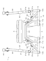
既設の便器に取り付ける便器用手摺としては、例えば、図7に示すようなものがある。この便器用手摺60は、同図に示すように、床に設置された便器Aの左右両側に配設される一対のベースフレーム61、61と、それぞれのベースフレーム61、61の後方側に立設された起立部材62、62と、この起立部材62、62の上端部にそれぞれ支持された手摺部材63、63と、一対の起立部材62、62を、相互に連結する連結部材64と、便器Aの両側部を挟み込む一対の挟持部材65、65とを備えており、手摺部材63、63は、同図に二点鎖線で示すように、後方側に跳ね上げることができるようになっている。   An example of a handrail for a toilet attached to an existing toilet is shown in FIG. As shown in the figure, the handrail 60 for toilet bowl stands on a pair of base frames 61, 61 disposed on the left and right sides of the toilet A installed on the floor, and on the rear side of each base frame 61, 61. Standing members 62, 62 provided, handrail members 63, 63 supported on the upper ends of the standing members 62, 62, a connecting member 64 for mutually connecting the pair of standing members 62, 62, and a toilet A pair of sandwiching members 65 and 65 sandwiching both sides of A are provided, and the handrail members 63 and 63 can be flipped up to the rear side as indicated by a two-dot chain line in FIG. .

従って、車椅子に座った足腰の弱い老人等が用便を行う際は、便器Aの片側に車椅子を移動し、車椅子に近いほうの手摺部材63を跳ね上げて移動空間を確保した状態で、車椅子から便器Aに乗り移ることになる。   Therefore, when an elderly person with weak legs sitting on a wheelchair performs a stool, the wheelchair is moved to one side of the toilet A, and the handrail member 63 closer to the wheelchair is flipped up to secure a movement space. Will transfer to toilet A.

特開平10−201672号公報Japanese Patent Laid-Open No. 10-201672

しかしながら、上述したような便器用手摺60では、手摺部材63を跳ね上げることによって、車椅子から便器Aに乗り移る老人等の移動空間を開放することはできるが、床に設置されているフレーム61を老人等の移動経路から退避させることはできないので、老人等が車椅子から便器Aに乗り移る際に、フレーム61に足が引っかかり、円滑に乗り移ることができないといった問題がある。   However, in the toilet handrail 60 as described above, by moving up the handrail member 63, it is possible to open a moving space for an elderly person or the like who transfers from the wheelchair to the toilet bowl A, but the frame 61 installed on the floor is used for the elderly person. Therefore, there is a problem that when an elderly person or the like moves from the wheelchair to the toilet A, his / her legs get caught in the frame 61 and cannot be smoothly transferred.

そこで、この発明の課題は、車椅子からの乗り移り動作を円滑に行うことができる便器用手摺を提供することにある。   Then, the subject of this invention is providing the handrail for toilet bowls which can perform the transfer operation from a wheelchair smoothly.

上記の課題を解決するため、請求項1に係る発明は、洋風便器における床固定部の両側部に沿うように配設された一対の内フレームと、一対の前記内フレームにそれぞれ連結された一対の外フレームと、一対の前記内フレームを相互に連結する連結部材と、前記外フレームに立設された一対の起立部材と、前記起立部材の上端部にそれぞれ支持された手摺部材とを備え、前記外フレームの前端部が、前記洋風便器の前後方向の中央部付近に位置しており、前記手摺部材が、前記洋風便器の後部側に退避可能に前記起立部材に支持されていることを特徴とする便器用手摺を提供するものである。   In order to solve the above problems, an invention according to claim 1 is a pair of inner frames disposed along both sides of a floor fixing portion in a Western-style toilet, and a pair connected to the pair of inner frames, respectively. An outer frame, a pair of connecting members that connect the pair of inner frames to each other, a pair of standing members that are erected on the outer frame, and handrail members that are respectively supported by the upper ends of the standing members, A front end portion of the outer frame is located in the vicinity of a central portion in the front-rear direction of the Western-style toilet, and the handrail member is supported by the standing member so as to be retractable to a rear side of the Western-style toilet. A handrail for toilet bowl is provided.

また、請求項2に係る発明は、請求項1に係る発明の便器用手摺において、前記連結部材が、前記洋風便器における床固定部の前端上部を取り囲むように、前記内フレームの後部側から前方に向かって斜め上方に立ち上がっていることを特徴としている。   Further, the invention according to claim 2 is the toilet handrail of the invention according to claim 1, wherein the connecting member is forward from the rear side of the inner frame so as to surround a front end upper portion of the floor fixing portion in the western style toilet. It is characterized by standing up diagonally upward.

以上のように、請求項1に係る発明の便器用手摺は、洋風便器における床固定部の両側部に沿うように配設された一対の内フレームにそれぞれ連結された一対の外フレームの前端部が、洋風便器の前後方向の中央部付近に位置しており、しかも、外フレームに立設された一対の起立部材の上端部には、手摺部材が後部側に退避可能に支持されているので、洋風便器の一方の側部側に位置している車椅子から老人等が洋風便器に乗り移る際、手摺部材を後部側に退避させると、老人等の移動経路に全く障害物がなくなり、老人等が車椅子から洋風便器に円滑かつ確実に乗り移ることができる。   As described above, the handrail for a toilet of the invention according to claim 1 is a front end portion of a pair of outer frames respectively connected to a pair of inner frames arranged along both side portions of a floor fixing portion in a Western-style toilet. However, since the handrail member is supported by the upper end portions of the pair of upright members erected on the outer frame so as to be retractable to the rear side. When an elderly person or the like moves from a wheelchair located on one side of the Western-style toilet to the Western-style toilet, if the handrail member is retracted to the rear side, there will be no obstacles in the movement path of the elderly person, You can transfer from a wheelchair to a Western-style toilet smoothly and reliably.

また、請求項2に係る発明の便器用手摺は、一対の内フレームを相互に連結する連結部材が洋風便器における床固定部の前端上部を取り囲むように、内フレームの後部側から前方に向かって斜め上方に立ち上がっているので、連結部材が、足腰の弱い老人が用便姿勢から立ち上がる際に行う、いずれか一方の足を後方に移動させるという立ち上がり動作の障害にならず、足腰の弱い老人がスムースに便器から立ち上がることができる。   Further, the handrail for a toilet of the invention according to claim 2 is directed from the rear side of the inner frame toward the front so that the connecting member for connecting the pair of inner frames to each other surrounds the front end upper portion of the floor fixing portion in the western style toilet. Since the connecting member stands up diagonally, the connecting member does not obstruct the standing action of moving one of the legs backward when an elderly person with weak legs and legs stands up from the toilet posture. You can get up from the toilet smoothly.

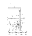
以下、実施の形態について図面を参照して説明する。図1〜図4に示すように、この便器用手摺1は、便所の床に固定設置された便器Aの床固定部aの両側部に設置される左右一対のベース部材10と、左右一対のベース部材10を相互に連結する連結部材20と、各ベース部材10にそれぞれ立設された左右一対の起立部材30と、各起立部材30の上端部にそれぞれ支持された左右一対の手摺部材40と、各ベース部材10に取り付けられた左右一対の固定部材50とから構成されている。   Hereinafter, embodiments will be described with reference to the drawings. As shown in FIGS. 1 to 4, the handrail 1 for toilet bowl includes a pair of left and right base members 10 installed on both sides of a floor fixing part a of a toilet A fixedly installed on the floor of a toilet, and a pair of left and right base members 10. A connecting member 20 that connects the base members 10 to each other, a pair of left and right standing members 30 that are erected on each base member 10, and a pair of left and right handrail members 40 that are respectively supported by the upper ends of the standing members 30. , And a pair of left and right fixing members 50 attached to each base member 10.

前記ベース部材10は、便所の床に固定設置された便器Aの床固定部aの側部に沿うように配設された、前端側が内側に屈曲した金属製の角パイプからなる内フレーム11と、この内フレーム11の外側に一定間隔を開けた状態で配設された、便器Aの前後方向に延びる短い金属製の角パイプからなる外フレーム12と、内フレーム11と外フレーム12とを相互に連結する金属製の角パイプからなる連結フレーム13とから構成されており、内フレーム11は、便器Aの床固定部aの前端部まで延びだしているが、外フレーム12は、その前端部が便器Aの前後方向の中央部付近に位置している。   The base member 10 is disposed along the side of the floor fixing part a of the toilet A fixedly installed on the floor of the toilet, and has an inner frame 11 made of a metal square pipe whose front end is bent inward. The outer frame 12 made of a short metal square pipe disposed in the front-rear direction of the toilet A, and the inner frame 11 and the outer frame 12, which are disposed outside the inner frame 11 at a predetermined interval. The inner frame 11 extends to the front end portion of the floor fixing portion a of the toilet bowl A, while the outer frame 12 has its front end portion. Is located near the center of the toilet A in the front-rear direction.

前記連結部材20は、便器Aにおける床固定部aの前端上部を取り囲むように、略U字状に屈曲させた金属製の角パイプによって形成されており、便器Aにおける床固定部aの側面に沿うように、双方の内フレーム11の後部側から、前方に向かって斜め上方に立ち上がっている。   The connecting member 20 is formed of a metal square pipe bent in a substantially U shape so as to surround the upper front end of the floor fixing part a in the toilet bowl A, and is formed on the side surface of the floor fixing part a in the toilet bowl A. As it goes along, it stands up diagonally upward toward the front from the rear side of both inner frames 11.

前記起立部材30は、上端側が僅かに内側(便器A側)に傾斜した状態でベース部材10の外フレーム12に固着された金属製の角パイプからなる下部支柱31と、この下部支柱31にその上端側から差し込まれて、下部支柱31内を上下にスライドする金属製の角パイプからなる上部支柱32とから構成されており、この上部支柱32の上端部に手摺部材40が支持されている。   The upright member 30 includes a lower column 31 made of a metal square pipe fixed to the outer frame 12 of the base member 10 with its upper end side slightly inclined inward (toilet A side), The upper column 32 is composed of a metal square pipe that is inserted from the upper end side and slides up and down in the lower column 31. A handrail member 40 is supported on the upper end of the upper column 32.

また、下部支柱31の前面には複数のボルト挿通孔31aが上下に形成されており、いずれかのボルト挿通孔31aに通したノブボルト33を、上部支柱32の下部前面に形成されたねじ孔(図示せず)にねじ込んで締め付けることにより、上部支柱32を所定の高さに段階的に固定することができるようになっている。   Also, a plurality of bolt insertion holes 31 a are formed vertically on the front surface of the lower support column 31, and a knob bolt 33 passed through any one of the bolt insertion holes 31 a is screw holes ( The upper support column 32 can be fixed to a predetermined height in a stepwise manner by screwing and tightening it (not shown).

前記手摺部材40は、後端部が起立部材30の上部支柱32の上端部に回動可能に支持された金属製の手摺本体に樹脂製のカバーを被せたものであり、図6(a)に示すように、水平状態から跳ね上げて、略垂直状態まで回動させることができるようになっている。   The handrail member 40 has a rear end portion covered with a resin cover on a metal handrail body rotatably supported on the upper end portion of the upper support column 32 of the upright member 30. FIG. As shown in FIG. 4, the robot can be flipped up from the horizontal state and rotated to a substantially vertical state.

前記固定部材50は、図5に示すように、ベース部材10の連結フレーム13の外端部から内側に向かって斜め上方に立ち上がる一対の固定アーム51と、それぞれの固定アーム51にその上端から差し込まれて、上下方向にスライドする可動アーム52と、可動アーム52の先端に取り付けられ、便器Aの湾曲した上部外表面bに当接して押圧する押圧部54とから構成されており、前記固定アーム51及び可動アーム52は、金属製の角パイプによって形成されている。   As shown in FIG. 5, the fixing member 50 is inserted into the pair of fixed arms 51 from the upper ends thereof, and a pair of fixed arms 51 that rise obliquely upward from the outer end of the connecting frame 13 of the base member 10. The movable arm 52 that slides in the vertical direction, and a pressing portion 54 that is attached to the tip of the movable arm 52 and presses against the curved upper outer surface b of the toilet bowl A. 51 and the movable arm 52 are formed by metal square pipes.

また、固定アーム51の外側面には上下方向に延びる長孔51aが形成されており、この長孔51aに通したノブボルト53を、可動アーム52の下端部に形成されたねじ孔(図示せず)にねじ込んで締め付けることにより、長孔51aの長さの範囲内で可動アーム52を任意の位置に固定することができるようになっている。   A long hole 51 a extending in the vertical direction is formed on the outer surface of the fixed arm 51, and a knob bolt 53 passed through the long hole 51 a is screwed into a screw hole (not shown) formed in the lower end portion of the movable arm 52. The movable arm 52 can be fixed at an arbitrary position within the range of the length of the long hole 51a.

前記押圧部54は、同図に示すように、可動アーム52の上端に取り付けられたアジャスタ55と、このアジャスタ55に取り付けられた自在アタッチメント56とから構成されている。   As shown in the figure, the pressing portion 54 includes an adjuster 55 attached to the upper end of the movable arm 52 and a free attachment 56 attached to the adjuster 55.

前記アジャスタ55は、可動アーム52の上端に形成されたネジ孔(図示せず)にねじ込まれる全ネジボルト55aと、この全ネジボルト55aに固定された、全ネジボルト55aを回転させるための回転操作部55bとから構成されており、回転操作部55bを回転させることで、全ネジボルト55aが回転しながら進退し、自在アタッチメント56が、固定アーム51の延びだし方向に進退するようになっている。   The adjuster 55 includes a total screw bolt 55a that is screwed into a screw hole (not shown) formed at the upper end of the movable arm 52, and a rotation operation unit 55b that is fixed to the total screw bolt 55a and that rotates the total screw bolt 55a. By rotating the rotation operation part 55b, all the screw bolts 55a advance and retract while rotating, and the free attachment 56 advances and retracts in the extending direction of the fixed arm 51.

前記自在アタッチメント56は、自在継手を介してアジャスタ55に取り付けられており、図5に二点鎖線で示すように、便器Aの上部外表面bの湾曲状態に応じて、ある程度の自由度を持ってその接触角度を調整できるようになっている。   The universal attachment 56 is attached to the adjuster 55 via a universal joint, and has a certain degree of freedom according to the curved state of the upper outer surface b of the toilet bowl A, as shown by a two-dot chain line in FIG. The contact angle can be adjusted.

また、ベース部材10の内フレーム11及び外フレーム12の前後端には、それぞれの下面側に、高さ調整を行うためのアジャスタ11a、12aが取り付けられており、排水等を考慮して便所の床に傾斜が設けられている場合でも、それぞれのアジャスタ11a、12aによって部分的に高さ調整を行うことができるので、設置される便器用手摺1のがたつきをなくすことができる。   In addition, adjusters 11a and 12a for adjusting the height are attached to the front and rear ends of the inner frame 11 and the outer frame 12 of the base member 10, respectively, and in consideration of drainage, etc. Even when the floor is inclined, the height can be partially adjusted by the respective adjusters 11a and 12a, so that it is possible to eliminate rattling of the toilet handrail 1 to be installed.

以上のように、この便器用手摺1は、便器Aにおける床固定部aの両側部に沿うように配設された一対の内フレーム11にそれぞれ連結された一対の外フレーム12の前端部が、便器Aの前後方向の中央部付近に位置しており、しかも、外フレーム12に立設された一対の起立部材30の上端部には、手摺部材40が跳ね上げ可能に支持されているので、図6(a)、(b)に示すように、手摺部材40を跳ね上げると、便器Aの側部側に位置している車椅子から老人等が洋風便器に乗り移る際の老人等の移動経路(同図(b)における網掛け表示領域)に全く障害物がなくなり、老人等が車椅子から便器Aに円滑かつ確実に乗り移ることができる。   As described above, the handrail 1 for the toilet bowl has the front end portions of the pair of outer frames 12 respectively connected to the pair of inner frames 11 arranged along both sides of the floor fixing portion a in the toilet bowl A. Since the handrail member 40 is supported at the upper end portions of the pair of upright members 30 erected on the outer frame 12 so as to be flipped up, it is located near the central portion in the front-rear direction of the toilet bowl A. As shown in FIGS. 6A and 6B, when the handrail member 40 is flipped up, a moving path of the elderly and the like when the elderly and the like transfer from the wheelchair located on the side of the toilet A to the Western-style toilet ( Obstacles are completely eliminated in the shaded display area (b) of the figure, and an elderly person or the like can smoothly and reliably transfer from the wheelchair to the toilet A.

また、この便器用手摺1は、一対の内フレーム11、11を相互に連結する連結部材20が便器Aにおける床固定部aの前端上部を取り囲むように、内フレーム11、11の後部側から前方に向かって斜め上方に立ち上がっているので、便器Aの床固定部aの前側周辺部分に障害物がなくなり、連結部材20が、足腰の弱い老人が用便姿勢から立ち上がる際に行う、いずれか一方の足を後方に移動させるという立ち上がり動作の障害にならず、足腰の弱い老人がスムースに便器から立ち上がることができる。   In addition, the toilet handrail 1 is forward from the rear side of the inner frames 11, 11 so that the connecting member 20 that connects the pair of inner frames 11, 11 surrounds the upper front end of the floor fixing portion a in the toilet A. Since the obstacle is not present in the front peripheral portion of the floor fixing part a of the toilet A, the connecting member 20 is performed when an elderly person with weak legs stands up from the toilet posture. This makes it possible for an elderly person with weak legs to stand up smoothly from the toilet.

また、上述したように、固定部材50によって、便器Aの左右両側の湾曲した上部外表面bをそれぞれ斜め下方から押圧するようにしているので、左右方向の位置ズレやがたつきが阻止されるだけでなく、その反力によって、便器用手摺1自体が便所の床面に押しつけられるので、前側に位置している手摺部材40に力がかかった場合でも、便器用手摺1の後端部が持ち上がったりすることがなく、安定した設置状態が確保される。   Further, as described above, the fixing member 50 presses the curved upper outer surfaces b on both the left and right sides of the toilet bowl A from obliquely below, so that the positional deviation and rattling in the left-right direction are prevented. In addition, since the handrail 1 for the toilet bowl is pressed against the floor surface of the toilet by the reaction force, the rear end portion of the handrail 1 for the toilet bowl is applied even when a force is applied to the handrail member 40 located on the front side. A stable installation state is ensured without lifting.

なお、上述した実施形態では、便器Aにおける床固定部aの前端上部を取り囲むように、内フレーム11、11の後部側から前方に向かって斜め上方に立ち上がる連結部材20を採用しているが、これに限定されるものではなく、内フレーム11、11の先端部同士を連結する構成を採用することも可能である。   In the above-described embodiment, the connection member 20 that rises obliquely upward from the rear side of the inner frames 11 and 11 is employed so as to surround the front end upper portion of the floor fixing portion a in the toilet bowl A. It is not limited to this, The structure which connects the front-end | tip parts of the inner frames 11 and 11 is also possible.

この発明にかかる便器用手摺の一実施形態を示す斜視図である。It is a perspective view which shows one Embodiment of the handrail for toilet bowl concerning this invention. 同上の便器用手摺の設置状態を示す斜視図である。It is a perspective view which shows the installation state of the handrail for toilet bowl same as the above. 同上の便器用手摺の設置状態を示す正面図である。It is a front view which shows the installation state of the handrail for toilet bowl same as the above. 同上の便器用手摺の設置状態を示す側面図である。It is a side view which shows the installation state of the handrail for toilet bowl same as the above. 同上の便器用手摺の固定部材を示す詳細図である。It is detail drawing which shows the fixing member of the handrail for toilet bowl same as the above. (a)は同上の便器用手摺の手摺部材を跳ね上げた状態を示す側面図、(b)は同上の便器用手摺の手摺部材を跳ね上げた状態を示す平面図である。(A) is a side view which shows the state which raised the handrail member of the handrail for toilet bowl same as the above, (b) is a top view which shows the state which raised the handrail member of the handrail for toilet bowl same as the above. 従来の便器用手摺の設置状態を示す斜視図である。It is a perspective view which shows the installation state of the conventional handrail for toilet bowls.

符号の説明Explanation of symbols

1 便器用手摺
10 ベース部材
11 内フレーム
11a アジャスタ
12 外フレーム
12a アジャスタ
13 連結フレーム
20 連結部材
30 起立部材
31 下部支柱
31a ボルト挿通孔
32 上部支柱
33 ノブボルト
40 手摺部材
50 固定部材
51 固定アーム
51a 長孔
52 可動アーム
53 ノブボルト
54 押圧部
55 アジャスタ
55a 全ネジボルト
55b 回転操作部
56 自在アタッチメント
A 便器
a 床固定部
b 上部外表面
DESCRIPTION OF SYMBOLS 1 Handrail for toilet bowl 10 Base member 11 Inner frame 11a Adjuster 12 Outer frame 12a Adjuster 13 Connection frame 20 Connection member 30 Standing member 31 Lower column 31a Bolt insertion hole 32 Upper column 33 Knob bolt 40 Handrail member 50 Fixed member 51 Fixed arm 51a Long hole 52 Movable arm 53 Knob bolt 54 Press part 55 Adjuster 55a Full screw bolt 55b Rotation operation part 56 Free attachment A Toilet a Floor fixing part b Upper outer surface

Claims (2)

洋風便器における床固定部の両側部に沿うように配設された一対の内フレームと、
一対の前記内フレームにそれぞれ連結された一対の外フレームと、
一対の前記内フレームを相互に連結する連結部材と、
前記外フレームに立設された一対の起立部材と、
前記起立部材の上端部にそれぞれ支持された手摺部材と
を備え、
前記外フレームの前端部が、前記洋風便器の前後方向の中央部付近に位置しており、
前記手摺部材が、前記洋風便器の後部側に退避可能に前記起立部材に支持されていることを特徴とする便器用手摺。
A pair of inner frames arranged along both sides of the floor fixing portion in the Western-style toilet;
A pair of outer frames respectively connected to the pair of inner frames;
A connecting member for connecting the pair of inner frames to each other;
A pair of upright members erected on the outer frame;
A handrail member supported respectively on the upper end of the upright member,
The front end of the outer frame is located near the center in the front-rear direction of the Western-style toilet,
The handrail for a toilet bowl, wherein the handrail member is supported by the upright member so as to be retractable to a rear side of the Western-style toilet.
前記連結部材は、前記洋風便器における床固定部の前端上部を取り囲むように、前記内フレームの後部側から前方に向かって斜め上方に立ち上がっている請求項1に記載の便器用手摺。   The toilet handrail according to claim 1, wherein the connecting member rises obliquely upward from the rear side of the inner frame toward the front so as to surround a front end upper portion of a floor fixing portion in the Western-style toilet.
JP2007213408A 2007-08-20 2007-08-20 Handrail for toilet Pending JP2009045196A (en)

Priority Applications (1)

Application Number Priority Date Filing Date Title
JP2007213408A JP2009045196A (en) 2007-08-20 2007-08-20 Handrail for toilet

Applications Claiming Priority (1)

Application Number Priority Date Filing Date Title
JP2007213408A JP2009045196A (en) 2007-08-20 2007-08-20 Handrail for toilet

Publications (1)

Publication Number Publication Date
JP2009045196A true JP2009045196A (en) 2009-03-05

Family

ID=40498000

Family Applications (1)

Application Number Title Priority Date Filing Date
JP2007213408A Pending JP2009045196A (en) 2007-08-20 2007-08-20 Handrail for toilet

Country Status (1)

Country Link
JP (1) JP2009045196A (en)

Cited By (3)

* Cited by examiner, † Cited by third party
Publication number Priority date Publication date Assignee Title
JP2011019804A (en) * 2009-07-17 2011-02-03 Om Kiki Corp Handrail device for toilet
JP2012217718A (en) * 2011-04-12 2012-11-12 Kyoritsu Kogyo Kk Handrail for toilet bowl
JP2012217711A (en) * 2011-04-12 2012-11-12 Kyoritsu Kogyo Kk Handrail for toilet bowl

Similar Documents

Publication Publication Date Title
CN110101330B (en) Toilet seat auxiliary device with lifting device
JP2009045196A (en) Handrail for toilet
JP5524895B2 (en) Toilet handrail
JP2009297465A (en) Handrail for toilet
JP2017042503A (en) Hand rail for toilet bowl
JP2981182B2 (en) Handrail for toilet
JP2011078459A (en) Handrail for toilet bowl
JP5524690B2 (en) Nursing handrail
JP6558842B2 (en) Wheelchair fixing device
JP3042985B2 (en) Handrail for toilet
JP5250793B2 (en) wheelchair
JP4948872B2 (en) Folding table
JP2017079964A (en) Wheelchair with walking support function
JP6783131B2 (en) Toilet armrest device
JP5747106B1 (en) Toilet handrail
KR101197738B1 (en) Seat apparatus for toilet bowl
JP2014004281A (en) Handrail for toilet bowl
JP4137525B2 (en) Auxiliary equipment for toilet
JP6074276B2 (en) Toilet handrail
JPH11169321A (en) Hand rail for toilet
JP3173529U (en) Handrail lifting device
JP2004049571A (en) Auxiliary handrail for toilet
JP3852547B2 (en) Armrest device for seated toilet
JP6685591B2 (en) Handrail device for toilet bowl
JP2016146991A (en) Handrail for toilet bowl