JP2009042667A - Liquid developing device and image forming apparatus mounted with tha same - Google Patents
Liquid developing device and image forming apparatus mounted with tha same Download PDFInfo
- Publication number
- JP2009042667A JP2009042667A JP2007210023A JP2007210023A JP2009042667A JP 2009042667 A JP2009042667 A JP 2009042667A JP 2007210023 A JP2007210023 A JP 2007210023A JP 2007210023 A JP2007210023 A JP 2007210023A JP 2009042667 A JP2009042667 A JP 2009042667A
- Authority
- JP
- Japan
- Prior art keywords
- roller
- liquid
- liquid developer
- bias voltage
- toner
- Prior art date
- Legal status (The legal status is an assumption and is not a legal conclusion. Google has not performed a legal analysis and makes no representation as to the accuracy of the status listed.)
- Pending
Links
Images


Landscapes
- Developing For Electrophotography (AREA)
- Wet Developing In Electrophotography (AREA)
Abstract
Description
本発明は、複写機やプリンタに代表される画像形成装置に適用可能な液体現像装置に関する。また、この液体現像装置を搭載した画像形成装置に関する。 The present invention relates to a liquid developing device applicable to an image forming apparatus represented by a copying machine or a printer. The present invention also relates to an image forming apparatus equipped with the liquid developing device.
複写機やプリンタ等の電子写真方式の画像形成装置においては、像担持体として感光体ドラムが広く用いられている。感光体ドラムを用いた一般的な画像形成動作は以下のようである。感光体ドラムの表面は帯電装置により所定電位で一様に帯電せしめられ、そこに露光装置のLED光等を照射することにより部分的に電位が光減衰して原稿画像の静電潜像が形成される。この静電潜像を現像装置で現像することにより、感光体ドラム表面にトナー像が形成される。そして、このトナー像は、感光体ドラムと転写部材とを接触、或いは近接させて構成した転写領域に用紙を挿通する時に、用紙に転写される。 In an electrophotographic image forming apparatus such as a copying machine or a printer, a photosensitive drum is widely used as an image carrier. A general image forming operation using the photosensitive drum is as follows. The surface of the photosensitive drum is uniformly charged with a predetermined potential by a charging device, and by irradiating the LED light or the like of the exposure device there, the potential is partially attenuated to form an electrostatic latent image of an original image. Is done. By developing the electrostatic latent image with a developing device, a toner image is formed on the surface of the photosensitive drum. The toner image is transferred onto the sheet when the sheet is inserted into a transfer region formed by bringing the photosensitive drum and the transfer member into contact with or in close proximity to each other.
静電潜像を現像する方法としては、乾式現像方式と、湿式現像方式とが存在する。このうち湿式現像方式では、液体現像剤が使用される。液体現像剤は、絶縁性液体、すなわち電気的に中性の溶媒であるキャリア液に、トナー粒子が高濃度で分散するように調整されている。そして、湿式画像形成装置は、液体現像装置を搭載しており、感光体ドラム上に形成された静電潜像を、液体現像装置の現像剤担持体である現像ローラから供給する液体現像剤によって現像する。 As a method for developing an electrostatic latent image, there are a dry development method and a wet development method. Among these, in the wet development method, a liquid developer is used. The liquid developer is adjusted so that toner particles are dispersed at a high concentration in an insulating liquid, that is, a carrier liquid which is an electrically neutral solvent. The wet image forming apparatus is equipped with a liquid developing device, and the electrostatic latent image formed on the photosensitive drum is supplied by a liquid developer supplied from a developing roller which is a developer carrying member of the liquid developing device. develop.
現像ローラに液体現像剤を供給する供給ローラには、現像ローラ表面に、液体現像剤の均一な薄層を形成する目的として、従来アニロックスローラが用いられている。アニロックスローラは、フレキソ印刷といった印刷技術における液体インクの供給ローラとして特に広く知られ、その外周面に多数の微細凹状セルが設けられている。 Conventionally, an anilox roller is used as a supply roller for supplying the liquid developer to the developing roller for the purpose of forming a uniform thin layer of the liquid developer on the surface of the developing roller. The anilox roller is particularly widely known as a liquid ink supply roller in a printing technique such as flexographic printing, and a large number of fine concave cells are provided on the outer peripheral surface thereof.
現像剤タンクから汲み上げられ、アニロックスローラに受け渡された液体現像剤は、アニロックスローラ表面の各セルに保持され、現像ローラ表面まで搬送される。このとき、規制部材であるドクターブレードでアニロックスローラの表面をドクタリングすることにより、各セルに、正確に規定された液量の液体現像剤が残り、この液体現像剤が現像ローラ表面に供給されて均一な薄層を形成するようになっている。 The liquid developer drawn up from the developer tank and delivered to the anilox roller is held in each cell on the surface of the anilox roller and conveyed to the surface of the development roller. At this time, the surface of the anilox roller is doctored with a doctor blade as a regulating member, so that a liquid developer having a precisely defined amount of liquid remains in each cell, and this liquid developer is supplied to the surface of the development roller. A uniform thin layer is formed.
上記のような液体現像剤の供給過程においては、アニロックスローラのセル内で沈降したトナー粒子等の固形物が堆積し、セル底部に固着してしまう問題が発生することがある。このような状況に陥ると、現像ローラ表面に液体現像剤の適正な薄層を形成することができなくなり、画像品質に悪影響を及ぼす恐れがある。したがって、アニロックスローラのセル内にトナー粒子等の固形物が堆積しないように特に注意を払わなければならない。こうした問題に対処するために、一般的には、オペレータ等が、定期的に点検を行い、必要に応じてアニロックスローラのセルを清掃するなどのメンテナンスを行って、セルの状態を適正に保っている。 In the liquid developer supply process as described above, solid matter such as toner particles settled in the cell of the anilox roller may be accumulated and fixed to the cell bottom. In such a situation, an appropriate thin layer of liquid developer cannot be formed on the surface of the developing roller, which may adversely affect image quality. Therefore, special care must be taken not to deposit solids such as toner particles in the cells of the anilox roller. In order to deal with such problems, in general, operators or the like regularly inspect and perform maintenance such as cleaning the anilox roller cell as necessary to maintain the cell state properly. Yes.
しかしながら、このようなメンテナンスは手間が掛かる上に、メンテナンスまでの間はセルへのトナー粒子等の堆積が進行するので、徐々に画像品質が低下してしまう可能性がある。そこで、こうした問題を解決すべく、液体現像剤中に混入した異物を除去する方法が提案され、その一例を特許文献1に見ることができる。特許文献1に記載された液体現像装置は、ブラシ状の異物除去手段を塗布ローラ(アニロックスローラ)表面に接触するように設け、液体現像剤中に混入した塵埃や紙粉等の異物を除去するようにしている。
特許文献1に記載された液体現像装置のように、アニロックスローラ表面に接触するブラシ状の異物除去手段を用いることにより、セル底部にトナー粒子が滞留しないようにすることができ、セル内におけるトナー粒子の堆積、固着を防止することが可能である。しかしながら、この構成では、アニロックスローラに接触する部材として、ドクターブレードのような規制部材とは別に、異物除去手段を設けなければならない。このように、規制部材と異物除去手段とを別々に設けると、液体現像装置内に広いスペースを確保する必要があり、液体現像装置の大型化、さらに画像形成装置の大型化を招く恐れがある。また、規制部材と異物除去手段とを別々に設けると、部品点数が増加するとともに製造工程も増加するので、大幅なコストアップが懸念される。 As in the liquid developing device described in Patent Document 1, it is possible to prevent toner particles from staying at the bottom of the cell by using a brush-like foreign substance removing means that contacts the surface of the anilox roller. It is possible to prevent the accumulation and sticking of particles. However, in this configuration, a foreign matter removing means must be provided as a member that contacts the anilox roller, separately from the regulating member such as a doctor blade. As described above, if the regulating member and the foreign matter removing unit are provided separately, it is necessary to secure a wide space in the liquid developing device, which may increase the size of the liquid developing device and the size of the image forming apparatus. . Further, if the regulating member and the foreign matter removing means are provided separately, the number of parts increases and the manufacturing process also increases.
本発明は、上記の点に鑑みてなされたものであり、現像剤担持体に液体現像剤を供給する供給ローラに対して、その表面をクリーニングするクリーニング部材を別途設けることなく、部品点数の増加防止、省スペース化が図られ、且つ液体現像剤中のトナー粒子の特性を利用して、メンテナンスに手間を掛けることなく、供給ローラ表面のセル底部へのトナー粒子の堆積、固着を防止することができ、適正な画像品質を維持することが可能な液体現像装置を提供することを目的とする。また、このような液体現像装置を搭載した高性能な画像形成装置を提供することを目的とする。 The present invention has been made in view of the above points, and an increase in the number of parts can be achieved without separately providing a cleaning member for cleaning the surface of a supply roller for supplying a liquid developer to a developer carrying member. Preventing toner particles from depositing and sticking to the bottom of the cell on the surface of the supply roller without taking time for maintenance by utilizing the characteristics of the toner particles in the liquid developer. An object of the present invention is to provide a liquid developing apparatus capable of maintaining an appropriate image quality. It is another object of the present invention to provide a high-performance image forming apparatus equipped with such a liquid developing device.
上記の課題を解決するため、本発明は、像担持体と、前記像担持体に絶縁性液体中にトナーを分散した液体現像剤を供給する現像剤担持体と、前記現像剤担持体に液体現像剤を供給する供給ローラとを備えた液体現像装置において、前記供給ローラに当接して設けられた導電性材料からなるローラ状規制部材に、バイアス電圧印加手段により、トナーの帯電極性と逆極性のバイアス電圧を印加することとした。 In order to solve the above problems, the present invention provides an image carrier, a developer carrier for supplying a liquid developer in which toner is dispersed in an insulating liquid to the image carrier, and a liquid on the developer carrier. In a liquid developing device including a supply roller for supplying a developer, a roller-shaped regulating member made of a conductive material provided in contact with the supply roller is opposite to the charged polarity of toner by a bias voltage applying unit. The bias voltage was applied.
また、上記構成の液体現像装置において、前記供給ローラは、内部が導電性材料で、表面が絶縁材料で構成されており、前記バイアス電圧印加手段により、トナーの帯電極性と同極性のバイアス電圧が印加されることとした。 In the liquid developing apparatus having the above-described configuration, the supply roller has a conductive material inside and a surface formed of an insulating material, and the bias voltage applying unit applies a bias voltage having the same polarity as the charging polarity of the toner. It was decided to be applied.
また、上記構成の液体現像装置において、前記供給ローラ表面の前記絶縁材料は、セラミックで構成されていることとした。 In the liquid developing apparatus having the above-described configuration, the insulating material on the surface of the supply roller is made of ceramic.
また、上記構成の液体現像装置において、前記バイアス電圧印加手段による前記ローラ状規制部材へのバイアス電圧の印加は、ローラ状規制部材と前記供給ローラの間を通過中の液体現像剤をトナー像の形成に用いる時に行うこととした。 In the liquid developing device having the above configuration, the bias voltage applied to the roller-shaped regulating member by the bias voltage applying unit may cause the liquid developer passing between the roller-shaped regulating member and the supply roller to be transferred to the toner image. This was done when used for formation.
また、上記構成の液体現像装置において、前記ローラ状規制部材と前記供給ローラの間を通過中の液体現像剤をトナー像の形成に用いない時には、前記バイアス電圧印加手段により、前記ローラ状規制部材に、トナーの帯電極性と同極性で、且つ前記供給ローラのバイアス電圧の絶対値よりも高いバイアス電圧を印加することが可能であることとした。 In the liquid developing device having the above-described configuration, when the liquid developer passing between the roller-shaped regulating member and the supply roller is not used for forming a toner image, the roller-shaped regulating member is formed by the bias voltage applying unit. In addition, it is possible to apply a bias voltage having the same polarity as the charging polarity of the toner and higher than the absolute value of the bias voltage of the supply roller.
また、上記構成の液体現像装置において、前記ローラ状規制部材は、その表面が弾性材料で構成されていることとした。 In the liquid developing device having the above-described configuration, the roller-like regulating member has a surface made of an elastic material.
また本発明では、上記液体現像装置を画像形成装置に搭載することとした。 In the present invention, the liquid developing device is mounted on the image forming apparatus.
本発明の構成によれば、像担持体と、像担持体に絶縁性液体中にトナーを分散した液体現像剤を供給する現像剤担持体と、現像剤担持体に液体現像剤を供給する供給ローラとを備えた液体現像装置において、供給ローラに当接して設けられた導電性材料からなるローラ状規制部材に、バイアス電圧印加手段により、トナーの帯電極性と逆極性のバイアス電圧を印加することとしたので、汲み上げローラから供給ローラ表面の各セル内に受け渡された液体現像剤が、ローラ状規制部材との当接部でドクタリングされて、各セルに、正確に規定された液量が残るのと同時に、バイアス電圧の作用により、セル内で、液体現像剤中のトナー粒子が、トナー粒子の帯電極性と逆極性に帯電したローラ状規制部材に引き寄せられて、表層に集合せしめられる。 According to the configuration of the present invention, the image carrier, the developer carrier that supplies the image carrier with the liquid developer in which the toner is dispersed in the insulating liquid, and the supply that supplies the liquid developer to the developer carrier. In a liquid developing apparatus including a roller, a bias voltage having a polarity opposite to the toner charging polarity is applied to a roller-shaped regulating member made of a conductive material in contact with the supply roller by a bias voltage applying unit. Therefore, the liquid developer delivered from the pumping roller into each cell on the surface of the supply roller is doctored at the contact portion with the roller-shaped regulating member, and the liquid volume precisely defined in each cell. At the same time, the toner particles in the liquid developer are attracted to the roller-shaped regulating member charged in the opposite polarity to the charged polarity of the toner particles in the cell due to the action of the bias voltage, and are collected on the surface layer. That.
これにより、セル内において、表層部には、トナー粒子の含有率が高い高濃度の液体現像剤層が形成され、セル底部である下層には、トナー粒子の含有率が低い低濃度の液体現像剤層が形成される。したがって、現像剤担持体には、供給ローラのセルの表層部に形成された高濃度液体現像剤層が供給され、現像剤担持体表面に形成される液体現像剤の薄層は、通常の液体現像剤よりも高濃度のトナー粒子を含有する。その結果、供給ローラまで、或いは液体現像装置までの液体現像剤の搬送経路では、実際に現像に使用する液体現像剤よりも低濃度、すなわち低粘度の液体現像剤の搬送を行えばよいので、粘度が高いことによる流動性の悪さに対する策を講じる必要がなくなり、簡便な構成にすることができる。 As a result, in the cell, a high-concentration liquid developer layer having a high toner particle content is formed on the surface layer, and a low-concentration liquid development having a low toner particle content is formed in the lower layer, which is the cell bottom. An agent layer is formed. Accordingly, the developer carrier is supplied with a high-concentration liquid developer layer formed on the surface layer of the cell of the supply roller, and the thin layer of liquid developer formed on the surface of the developer carrier is a normal liquid. Contains toner particles at a higher concentration than the developer. As a result, in the transport path of the liquid developer up to the supply roller or the liquid developing device, it is sufficient to transport the liquid developer having a lower concentration than the liquid developer actually used for development, that is, a low viscosity. There is no need to take measures against poor fluidity due to high viscosity, and a simple configuration can be achieved.
そして、供給ローラの各セル内の多くのトナー粒子が、セル表層に引き寄せられて、現像剤担持体表面に供給されることにより、その後にセル底部に残留する液体現像剤に、トナー粒子が殆ど残らないようにすることができる。したがって、供給ローラ表面のセル底部へのトナー粒子の堆積、固着を防止することができ、セルの清掃を目的としたメンテナンスが不要になるとともに、供給ローラの長寿命化も図ることができる。このようにして、供給ローラに対して、その表面をクリーニングするクリーニング部材を別途設けることなく、部品点数の増加防止、省スペース化が図られ、使用時間や使用頻度に拘わらず、供給ローラのセルを現像に対して良好な状態に保持でき、適正な画像品質を長期間にわたって維持することが可能な液体現像装置を提供することができる。 Then, a large amount of toner particles in each cell of the supply roller are attracted to the cell surface layer and supplied to the surface of the developer carrying member, so that the liquid developer remaining at the bottom of the cell thereafter has almost no toner particles. It is possible not to remain. Therefore, it is possible to prevent toner particles from being deposited and adhered to the cell bottom portion on the surface of the supply roller, so that maintenance for the purpose of cleaning the cell is not required and the life of the supply roller can be extended. In this way, without providing a separate cleaning member for cleaning the surface of the supply roller, it is possible to prevent an increase in the number of components and save space, and the cell of the supply roller regardless of the usage time and frequency of use. Can be maintained in a favorable state with respect to development, and a liquid developing apparatus capable of maintaining appropriate image quality over a long period of time can be provided.
また、前記供給ローラは、内部が導電性材料で、表面が絶縁材料で構成されており、バイアス電圧印加手段により、トナーの帯電極性と同極性のバイアス電圧が印加されることとしたので、現像剤担持体やローラ状規制部材との絶縁性を保持しながら、供給ローラ内部の導電性材料にバイアス電圧を印加することにより、現像剤担持体やローラ状規制部材に対して電位差を発生させることができる。したがって、各バイアス電圧間を独立して制御することができ、制御の自由度を高めることが可能である。つまり、帯電しているトナー粒子に対して、現像剤担持体、ローラ状規制部材、及び供給ローラに印加するバイアス電圧を適宜個別に、あるいは相対的に調整することにより、液体現像剤中のトナー粒子の挙動を自在に制御することができる。その結果、液体現像剤中のトナー粒子の特性を利用して、供給ローラ表面のセル底部へのトナー粒子の堆積、固着を防止し、適正な画像品質を維持する効果を一層向上させることが可能になる。 The supply roller has a conductive material inside and an insulating material on the surface, and the bias voltage applying means applies a bias voltage having the same polarity as the toner charging polarity. Applying a bias voltage to the conductive material inside the supply roller while maintaining insulation from the developer carrier and the roller-shaped regulating member, generates a potential difference with respect to the developer carrier and the roller-shaped regulating member. Can do. Therefore, each bias voltage can be controlled independently, and the degree of freedom of control can be increased. In other words, the toner in the liquid developer is adjusted by appropriately adjusting the bias voltage applied to the developer carrying member, the roller-shaped regulating member, and the supply roller with respect to the charged toner particles individually or relatively. The behavior of the particles can be freely controlled. As a result, by utilizing the characteristics of the toner particles in the liquid developer, it is possible to prevent toner particles from accumulating and sticking to the cell bottom of the supply roller surface, and to further improve the effect of maintaining proper image quality. become.
また、前記供給ローラ表面の絶縁材料は、セラミックで構成されていることとしたので、その材料特性により精密なセルが形成できるのに加えて、耐久性、耐溶剤性が高められた供給ローラを得ることができる。これにより、長期間にわたって安定して、現像剤担持体表面に対して高濃度、高精度な液体現像剤の薄層を形成することが可能である。したがって、メンテナンスに手間が掛からず、長寿命化が図られ、さらに長期間にわたって適正な画像品質を維持することが可能な液体現像装置を得ることができる。 In addition, since the insulating material on the surface of the supply roller is made of ceramic, in addition to being able to form a precise cell due to its material characteristics, a supply roller with improved durability and solvent resistance is provided. Obtainable. Thereby, it is possible to form a thin layer of a liquid developer with high concentration and high accuracy on the surface of the developer carrying member stably over a long period of time. Therefore, it is possible to obtain a liquid developing apparatus that requires less labor for maintenance, has a long life, and can maintain an appropriate image quality for a long period of time.
また、前記バイアス電圧印加手段によるローラ状規制部材へのバイアス電圧の印加は、ローラ状規制部材と供給ローラの間を通過中の液体現像剤をトナー像の形成に用いる時に行うこととしたので、液体現像装置の起動中、画像形成時以外の期間においてもその表面に液体現像剤が存在する供給ローラに対して、ローラ状規制部材と供給ローラの間を通過中の液体現像剤をトナー像の形成に用いる時に限って、ローラ状規制部材にトナー粒子と逆極性、さらに供給ローラにトナー粒子と同極性のバイアス電圧を印加することで、液体現像剤中のトナー粒子を表層に集める効果を高めることができる。したがって、ローラ状規制部材と供給ローラの間を通過中の液体現像剤をトナー像の形成に用いる時には、供給ローラ表面のセルに対してトナー粒子の堆積、固着を防止しながら、高濃度の液体現像剤を得ることができる。 In addition, since the bias voltage is applied to the roller-shaped regulating member by the bias voltage applying means when the liquid developer passing between the roller-shaped regulating member and the supply roller is used for forming a toner image, During the startup of the liquid developing device, the liquid developer passing between the roller-shaped regulating member and the supply roller is transferred to the supply roller having the liquid developer on the surface even during a period other than the time of image formation. Only when it is used for formation, by applying a bias voltage having a polarity opposite to that of toner particles to the roller-shaped regulating member and to the supply roller having the same polarity as that of toner particles, the effect of collecting the toner particles in the liquid developer on the surface layer is enhanced. be able to. Therefore, when the liquid developer passing between the roller-shaped regulating member and the supply roller is used for forming a toner image, a high concentration liquid is prevented while preventing toner particles from accumulating and sticking to the cells on the surface of the supply roller. A developer can be obtained.
また、前記ローラ状規制部材と前記供給ローラの間を通過中の液体現像剤をトナー像の形成に用いない時には、前記バイアス電圧印加手段により、ローラ状規制部材に、トナーの帯電極性と同極性で、且つ供給ローラのバイアス電圧の絶対値よりも高いバイアス電圧を印加することが可能であることとしたので、ローラ状規制部材に付着した液体現像剤に対して、液体現像剤中のトナー粒子は、ローラ状規制部材と供給ローラに印加されたバイアス電圧の差によって、バイアス電圧の低いほうに移動しようとするため、供給ローラ側に移動する。これにより、ローラ状規制部材に付着したトナー粒子は除去され、適正な画像品質を維持する効果を高めることが可能になる。 Further, when the liquid developer passing between the roller-shaped regulating member and the supply roller is not used for forming a toner image, the bias voltage applying unit causes the roller-shaped regulating member to have the same polarity as the toner charging polarity. In addition, since it is possible to apply a bias voltage higher than the absolute value of the bias voltage of the supply roller, the toner particles in the liquid developer are in contrast to the liquid developer adhering to the roller-like regulating member. Moves to the supply roller side in order to move to the lower bias voltage due to the difference between the bias voltage applied to the roller-shaped regulating member and the supply roller. As a result, the toner particles adhering to the roller-like regulating member are removed, and the effect of maintaining proper image quality can be enhanced.
そして、上記のような動作は、前記ローラ状規制部材と前記供給ローラの間を通過中の液体現像剤をトナー像の形成に用いない時に行われることとしたので、例えば紙間や待機時などといった期間において、ローラ状規制部材に付着したトナー粒子を除去することができる。したがって、そのための特別な期間を設ける必要がなく、一連の画像形成動作の邪魔となることを防止することができ、利用者の利便性を損なうのを予防することが可能である。 The above-described operation is performed when the liquid developer passing between the roller-shaped regulating member and the supply roller is not used for forming a toner image. In such a period, the toner particles adhering to the roller-shaped regulating member can be removed. Therefore, it is not necessary to provide a special period for that purpose, and it is possible to prevent a series of image forming operations from being obstructed, and to prevent the user's convenience from being impaired.
また、前記ローラ状規制部材は、その表面が弾性材料で構成されていることとしたので、例えば供給ローラ表面にうねりが発生していたり、供給ローラに対してローラ状規制部材が傾斜した形で接触していたりしても、供給ローラの表面に沿った適正なドクタリングを行うことができる。これにより、供給ローラ表面の各セルには、正確に規定された液量の液体現像剤が残る。したがって、液体現像剤中のトナー粒子の特性を利用して、供給ローラ表面のセル底部へのトナー粒子の堆積、固着を防止しながら、適正な画像品質を維持する効果をより一層向上させることが可能になる。 Further, since the surface of the roller-like regulating member is made of an elastic material, for example, the surface of the supply roller is wavy, or the roller-like regulating member is inclined with respect to the supply roller. Even if they are in contact, appropriate doctoring along the surface of the supply roller can be performed. As a result, a liquid developer having a precisely defined liquid amount remains in each cell on the surface of the supply roller. Therefore, by utilizing the characteristics of the toner particles in the liquid developer, it is possible to further improve the effect of maintaining proper image quality while preventing the toner particles from being deposited and fixed on the cell bottom of the supply roller surface. It becomes possible.
また本発明では、上記液体現像装置を画像形成装置に搭載することとしたので、現像剤担持体に液体現像剤を供給する供給ローラに対して、その表面をクリーニングするクリーニング部材を別途設けることなく、部品点数の増加防止、省スペース化が図られ、且つ液体現像剤中のトナー粒子の特性を利用して、メンテナンスに手間を掛けることなく、供給ローラ表面のセル底部へのトナー粒子の堆積、固着を防止することができ、適正な画像品質を維持することが可能な高性能な画像形成装置を得ることができる。 In the present invention, since the liquid developing device is mounted on the image forming apparatus, a cleaning member for cleaning the surface of the supply roller for supplying the liquid developer to the developer carrying member is not separately provided. The increase in the number of parts, space saving, and the characteristics of the toner particles in the liquid developer are used to deposit toner particles on the bottom of the cell on the surface of the supply roller without troublesome maintenance. It is possible to obtain a high-performance image forming apparatus that can prevent sticking and can maintain appropriate image quality.
以下、本発明の実施形態を図1〜図3に基づき説明する。 Hereinafter, embodiments of the present invention will be described with reference to FIGS.
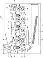
最初に、本発明の実施形態に係る液体現像装置を搭載した画像形成装置について、図1及び図2を用いてその構造の概略を説明しつつ、画像形成動作の概略を説明する。図1は画像形成装置の模型的垂直断面正面図、図2は図1に示した画像形成部の垂直断面部分拡大図である。この画像形成装置は、中間転写ベルトを用いてトナー像を用紙に転写する、所謂タンデム型のカラー印刷タイプのプリンタである。 First, an outline of an image forming operation of an image forming apparatus equipped with a liquid developing device according to an embodiment of the present invention will be described with reference to FIGS. 1 and 2. 1 is a schematic vertical sectional front view of the image forming apparatus, and FIG. 2 is a partially enlarged vertical sectional view of the image forming unit shown in FIG. This image forming apparatus is a so-called tandem type color printing type printer that transfers a toner image onto a sheet using an intermediate transfer belt.
図1のプリンタ100は、給紙部1、垂直搬送路2、レジストローラ対3、ベルト搬送部4、第1の画像形成部5B、第2の画像形成部5M、第3の画像形成部5C、第4の画像形成部5Y、2次転写部6、定着部7、排出搬送路8、排出トレイ9等から構成されている。
The
上記構成のプリンタ100は、次のような画像形成工程を行う。用紙Pは、本体下部に設けられた給紙部1の給紙カセット1aより、ピックアップローラ1bによって垂直搬送路2を上方に向かって送り出され、レジストローラ対3を介して2次転写部6へ搬送される。
The
給紙部1の上方において、中間転写体を無端ベルトの形で用いた中間転写ベルト43は、駆動ローラ41により、図1の矢印の方向に送られ、画像形成部5Y、5C、5M、5Bで、像担持体である各々の感光体ドラム51に形成されたイエロー、シアン、マゼンタ、ブラックの各色のトナー画像が順次転写され、中間転写ベルト43表面にカラー画像が形成される。
Above the paper feed unit 1, the
ここで形成されたカラー画像は、2次転写部6によって、中間転写ベルト43から、給紙カセット1aより搬送されてきた用紙Pに、2次転写されて、用紙P上にカラー画像が形成される。
The color image formed here is secondarily transferred by the
この後、未定着のカラー画像を転写された用紙Pは、中間転写ベルト43から分離され、定着部7に搬送される。そして、定着ローラ7aと加圧ローラ7bの圧接により形成される定着ニップ部にて、用紙Pに定着に必要な熱量が供給され、カラー画像の定着処理がされる。最後に、用紙Pは、定着部7で定着処理がなされた後に排出搬送路8を経て排出トレイ9に排出される。なお、定着ローラ7aには、ヒータ(不図示)が内蔵され、このヒータは定着に必要な所定の温度を発生するように制御されている。
Thereafter, the paper P on which the unfixed color image is transferred is separated from the
次に、上記プリンタ100の主要な構成要素である画像形成部5周辺の構成について、詳細に説明する。画像形成部5の周辺には、ベルト搬送部4と、液体現像装置を搭載する第1〜第4の画像形成部5B、5M、5C、5Yと、中間転写クリーニングユニット45とが備えられている。
Next, a configuration around the
ベルト搬送部4は、駆動ローラ41と、従動ローラ42と、この2つのローラに掛け渡された無端状の中間転写ベルト43とからなる。中間転写ベルト43は、テンションローラ44により、適度なテンションに保たれている。この状態で、駆動ローラ41は、駆動モータ(不図示)からその駆動力を伝達され、各画像形成部5における感光体ドラム51の外周速度と、ベルト搬送部4の中間転写ベルト43の外周速度が、等速になるように駆動されるようになっている。
The belt conveyance unit 4 includes a driving
第1〜第4の画像形成部5B、5M、5C、5Yは、ベルト搬送部4の下方に並んで配置されている。各画像形成部5の配置は、用紙搬送方向上流より順に、イエロー(5Y)、シアン(5C)、マゼンタ(5M)、ブラック(5B)用となっており、全て略同じ構成のユニットである。したがって、第1〜第4の画像形成部5B、5M、5C、5Yにおいて、以下の説明の用いる画像形成部5の構成と同一の構成である部分については同一の符号を付している。そして、以下の説明において、特に限定する必要がある場合を除き、「B」「M」「C」「Y」の識別記号は省略するものとする。
The first to fourth
図2に示すように、画像形成部5は、像担持体である感光体ドラム51、主帯電装置52、露光装置53、液体現像装置10、1次転写手段54、クリーニング装置55、除電ランプ59から構成され、樹脂等からなる筐体に組み付けることにより1つのユニットとなり、プリンタ100本体に取り付けられている。
As shown in FIG. 2, the
感光体ドラム51は、アモルファス・シリコンドラムを用いており、現像位置での暗電位が所定の電位になるよう主帯電装置52により帯電される。この帯電した感光体ドラム51の表面に露光装置53が画像情報に応じた光を照射することにより感光体ドラム51の表面に静電潜像が形成される。なお、露光装置53は、LPH(LED PRINT HEAD)や、LSU(レーザスキャニングユニット)を用いても良い。
The
液体現像装置10の現像剤タンク11には、トナー粒子と絶縁性液体であるキャリアからなる液体現像剤18が貯溜されている。液体現像剤18は、シリコンオイル等の非極性、すなわち、電気的に中性の溶媒であるキャリア液中にトナー粒子が高濃度で分散するように調整されている。トナー粒子は、着色剤、樹脂(バインダー)や必要に応じて帯電制御剤を含んでいる。樹脂(バインダー)は、着色剤に吸着し、キャリア液によく分散して、吸着された着色剤にプラス又はマイナスの電荷を印加する。本実施形態では、トナー粒子は、樹脂(バインダー)によってプラスに帯電している。なお、キャリア液としては、イソパラフィン系溶剤(例えば、アイソパーG(エクソン社製))、高級脂肪酸エステル、シリコンオイル等を用いることができる。
The
この液体現像剤18を、現像ローラ12から、感光体ドラム51の光が照射された部分の静電潜像に、供給することにより、感光体ドラム51にトナー像を現像する。
By supplying the
感光体ドラム51の暗電位がプラス300Vで、現像バイアスはプラス200V、露光後電位がプラス20Vとなるように設定されており、この現像バイアスと露光後電位の差がいわゆるコントラスト電位である。すなわち、暗電位は画像白部に相当し、露光後電位は画像黒部に相当する。上記のように形成された静電潜像が現像されたトナー像は、1次転写手段54とのニップにおいてベルト搬送部4の中間転写ベルト43に転写される。1次転写手段54は本実施形態では転写ローラを用いており、感光体ドラム51の表面電位とは逆極性の電圧がマイナス100〜マイナス1000Vの範囲に設定されたバイアス電圧が、印加されるようになっている。
The dark potential of the
感光体ドラム51上の転写されなかった残留トナー粒子は、クリーニング装置55のクリーニングローラ56及びクリーニングブレード57により除去され、重力の作用や、クリーニングローラ56の回転に従って排出スクリュー58の方へと送られ、排出スクリュー58によりハウジングの外部へと搬送される。除電ランプ59は、LED(発光ダイオード)などの除電光を感光体ドラム51に照射することにより、その表面の帯電電荷を除去し、次回の画像形成動作時における帯電工程のための準備を整える。なお、画像形成における電位設定は、感光体ドラム51の特性、トナー粒子の特性、環境等に応じて、最適な値が選択できるものである。
Residual toner particles that have not been transferred onto the
プリンタ100は、上述の画像形成部5の画像形成方法に基づいて、第1〜第4の画像形成部5B、5M、5C、5Yで、ブラック、マゼンタ、シアン、イエローに対応する画像を、各感光体ドラム51上に現像し、中間転写ベルト43上に順次繰り返し、ずれなく転写することで、1つのカラー画像の形成を行う。
Based on the image forming method of the
中間転写クリーニングユニット45は、図1に示すように、中間転写クリーニングローラ45aと、中間転写クリーニングブレード45bとを備えている。中間転写クリーニングローラ45aは、中間転写ベルト43に対して圧接されていて、中間転写ベルト43の回転方向と同方向に回転されている。中間転写クリーニングブレード45bは、中間転写ベルト43の移動方向における中間転写クリーニングローラ45aの位置から下流側にて、中間転写ベルト43に対して当接することにより、中間転写ベルト43上の転写残トナーを掻き落とす。
As shown in FIG. 1, the intermediate
次に、上記構成に係るプリンタ100に搭載された液体現像装置10の構成を、図2を参照して詳しく説明する。
Next, the configuration of the liquid developing
図2に示すように、本実施形態に係る液体現像装置10は、液体現像剤18を貯溜する現像剤タンク11を備えている。液体現像装置10内部には、現像ローラ12と、供給ローラであるアニロックスローラ13と、汲み上げローラ14と、ローラ状規制部材であるドクターローラ15と、クリーニングブレード16と、一対の撹拌スクリュー17a、17bとが設けられている。現像ローラ12、アニロックスローラ13、汲み上げローラ14、ドクターローラ15、及び撹拌スクリュー17a、17bは、共通の歯車列等からなる駆動手段により回転駆動される。
As shown in FIG. 2, the
現像剤タンク11には、液体現像剤18が貯溜されており、撹拌スクリュー17a、17bが液体現像剤18に浸漬するように設けられている。汲み上げローラ14は、現像剤タンク11内において、ローラの一部が液体現像剤18に浸漬するように設けられており、この上方に、供給ローラであるアニロックスローラ13が設けられている。そして、アニロックスローラ13の上方には、現像ローラ12が設けられている。
A
ローラ状規制部材であるドクターローラ15は、現像ローラ12とアニロックスローラ13との接触箇所に対してアニロックスローラ13回転方向上流側で、アニロックスローラ13の軸線方向と平行にして、アニロックスローラ13に当接させて設けられている。ドクターローラ15は、アニロックスローラ13のローラ面に供給された液体現像剤18を薄層化している。なお、感光体ドラム51は、液体現像装置10の外側にあって、現像ローラ12に当接している。
The
クリーニングブレード16は、感光体ドラム51と現像ローラ12との接触箇所に対して現像ローラ12回転方向下流側で、現像ローラ12にブレードの一端がカウンタ当接するように配置されている。クリーニングブレード16は、現像後に現像ローラ12上に残留した液体現像剤18を除去する。
The
次に、液体現像装置10の動作工程について説明する。
Next, an operation process of the liquid developing
図2において、液体現像剤18は、前述のように、キャリアとしてのシリコンオイル等からなる非極性の絶縁性液体中に、正電荷を有する微細な樹脂からなるトナー粒子(粒径約1μm)を分散混濁させたものである。現像剤タンク11に貯溜された液体現像剤18は、撹拌スクリュー17a、17bにより攪拌されて、トナー粒子が液中で均一になるように分散せしめられる。
In FIG. 2, as described above, the
液体現像剤18は、この液体現像剤18に一部浸漬している汲み上げローラ14が回転することにより、その浸漬したローラ表面に順次付着して、汲み上げられる。そして、アニロックスローラ13と汲み上げローラ14とのニップ部を通して、同期して回転するアニロックスローラ73のローラ面に順次塗布されていく。
The
アニロックスローラ13に塗布された液体現像剤18は、ドクターローラ15にて均一な薄層にされて、アニロックスローラ13に当接して、同期回転する現像ローラ12のローラ面に薄膜層として塗布される。その後、静電潜像が形成された感光体ドラム51に供給されて、感光体ドラム51上にトナー画像が現像される。
The
次に、本発明の特徴部分である、ローラ状規制部材であるドクターローラ15及び供給ローラであるアニロックスローラ13へのバイアス電圧印加による、トナーコンパクション、アニロックスローラ13、ドクターローラ15のクリーニングについて説明する。
Next, cleaning of the toner compaction, the
まず、この特徴部分の構成について、図2に加えて図3を参照して説明する。図3は、アニロックスローラ13及びドクターローラ15当接部における液体現像剤の様子を示す部分拡大断面図である。
First, the structure of this characteristic part will be described with reference to FIG. 3 in addition to FIG. FIG. 3 is a partial enlarged cross-sectional view showing the state of the liquid developer at the contact portions of the
図3に示すように、アニロックスローラ13は、外周面全体に多数の精密な微細凹状セル13cが規則正しく刻印されたローラである。各セル13cには、汲み上げローラ14から液体現像剤18が供給されるようになっている。アニロックスローラ13のセル13cを有する表面層13aは絶縁材料であるセラミックにより構成されており、ローラ内部13bは導電性材料により構成されている。なお、セル13cは、一本の連続した溝で構成されており、アニロックスローラ13の軸線方向に対して45度の角度で傾斜させ、螺旋状に刻印されている。セル13cの最深部の深さは約30μm、溝の幅は約100μm、溝同士の間隔は約25μmである。
As shown in FIG. 3, the
表面層13aのセラミックは、ローラ内部13bの表面に対して、例えば酸化クロムなどの金属酸化物を焼成、溶射することによって形成する。その層厚は、100〜200μmである。この表面層13aの外周面を研磨した後、その表面に、レーザーによって精密にセル13cを形成する。ローラ内部13bの導電性材料は、快削鋼鋼材(SUM材)で構成されている。
The ceramic of the
そして、図2に示すように、バイアス電圧印加手段19が、ローラ内部13bの導電性材料に接続されており、制御手段20の要求に従って、設定された値(プラス200V)のバイアス電圧をアニロックスローラ13に印加するようになっている。なお、アニロックスローラ13の表面層13aは絶縁材料であるセラミックであるので、アニロックスローラ13に当接する現像ローラ12やドクターローラ15にバイアス電圧が印加されている場合であっても、導通しないので電位差を維持することができる。
As shown in FIG. 2, the bias
ドクターローラ15は、前述のように、現像ローラ12とアニロックスローラ13との接触箇所に対してアニロックスローラ13回転方向上流側で、アニロックスローラ13の軸線方向と平行にして、アニロックスローラ13に当接させて設けられている(図2参照)。そして、ドクターローラ15は、図3に示すように、アニロックスローラ13との接触箇所に当接ニップ部Nが形成されるように、アニロックスローラ13に押し当てられている。また、ドクターローラ15は、アニロックスローラ13との当接箇所における表面が、アニロックスローラ13表面の移動方向とは異なる方向に移動するように、回転している。
As described above, the
ドクターローラ15は、金属製ローラ、または金属製芯材の表面に、弾性材料である導電性ゴムを設けた形で構成されている。導電性ゴムは、ウレタンゴムにカーボンを配合、或いは二トリルゴム(NBR)にエピクロロヒドリンを配合して構成し、その厚さは0.5〜1.0mmである。そして、表面の摩擦抵抗を軽減するため、ウレタンコートやフッ素樹脂コートなどのコーティングを施したり、PFA(ポリテトラフルオロエチレン)チューブを装着したりする場合もある。
The
ドクターローラ15には、図2に示すように、バイアス電圧印加手段19が接続されており、制御手段20の要求に従って、設定された値のバイアス電圧が印加されるようになっている。また、図示しないクリーニングローラが、ドクターローラ15表面をクリーニングするために設けられている。
As shown in FIG. 2, a bias
次に、上記構成に係る動作及び作用効果について説明する。まず、ドクターローラ15とアニロックスローラ13の間を通過中の液体現像剤18をトナー像の形成に用いる時における動作及び作用効果についての説明を行う。
Next, the operation and effect of the above configuration will be described. First, operations and effects when the
液体現像装置10において、現像剤タンク11に貯溜された液体現像剤18は、液体現像剤18に浸漬し、回転する汲み上げローラ14のローラ面に付着せしめられ、汲み上げローラ14の回転動作に伴って、同一線速度で逆方向に回転するアニロックスローラ13との当接部を介して、アニロックスローラ13の表面に順次供給される。この際、汲み上げローラ14と当接し、液体現像剤18の供給を受けたアニロックスローラ13の各セル13cは、液体現像剤18で満たされる。
In the liquid developing
液体現像剤18が満たされた各セル13cは、この後、アニロックスローラ13の回転に従って、ドクターローラ15との当接ニップ部Nに至る。
Each
図3に示すように、ドクターローラ15の手前においては、アニロックスローラ13に供給された液体現像剤18は、各セル13c内に留まらず、ローラ面全体に付着して、過剰な状態となっている。弾性を有するドクターローラ15の当接ニップ部Nでは、アニロックスローラ13表面に沿って密着している状態であるので、当該部位に至ったアニロックスローラ13上の液体現像剤18は、セル13c内に溜まっているものを除いては、ドクターローラ15との当接ニップ部N手前に残され、現像剤タンク11(図2参照)に戻される。このようなドクターローラ15によるドクタリングで、ドクターローラ15当接ニップ部Nを通過した後は、アニロックスローラ13表面に付着していた過剰な液体現像剤18が除去されて、各セル13c内には、略正確に規定された分量の液体現像剤18が残る。
As shown in FIG. 3, in front of the
ドクターローラ15とアニロックスローラ13の間を通過中の液体現像剤18をトナー像の形成に用いる時、ドクターローラ15には、制御手段20の要求を受けたバイアス電圧印加手段19により、液体現像剤18のトナー粒子の帯電極性(プラス)と逆極性(マイナス)のバイアス電圧(マイナス300V)が印加されている。これにより、セル13c内の液体現像剤18が規定分量に調整されると同時に、セル13c内の液体現像剤18に分散されているトナー粒子Tは、バイアス電圧が印加されたドクターローラ15の表面に引き寄せられる(トナーコンパクション現象、図3参照)。
When the
したがって、セル13c内の液体現像剤18においては、ドクターローラ15近傍である表層部には、トナー粒子Tの含有率が高い高濃度の液体現像剤18の層が形成され、セル13c底部である下層には、トナー粒子Tの含有率が低い低濃度の液体現像剤18の層が形成される。
Therefore, in the
そして、ここでセル13cの表層部に形成された高濃度の液体現像剤18の層は、略この状態を維持したまま、現像ローラ12との当接部に至って、ここで現像ローラ12のローラ面に転移せしめられて、現像ローラ12表面に液体現像剤18の薄層を形成する。
Then, the layer of the high-
一般的に、アニロックスローラ13から現像ローラ12に転移する液体現像剤18の量は、セル容量の30〜60%程度であり、セル13c内の全ての液体現像剤18が、現像ローラ12に転移することはない。したがって、アニロックスローラ13のセルの表層に高濃度の液体現像剤18の層を形成しておくことにより、高濃度の液体現像剤18が、より多く現像ローラ12に転移し、セル13c底部の低濃度の液体現像剤18が、残留することになる。
Generally, the amount of
よって、現像ローラ12に形成された液体現像剤18の薄層は、現像剤タンク11内で貯溜されている液体現像剤18よりも、トナー粒子Tを多く含有する高濃度の液体現像剤18の薄層となる。そして、現像ローラ12に形成された高濃度の液体現像剤18の薄層は、感光体ドラム51に供給されて静電潜像を現像する。
Therefore, the thin layer of the
このように、ドクターローラ15とアニロックスローラ13の間を通過中の液体現像剤18をトナー像の形成に用いる時に用いられる液体現像剤18はトナー濃度が高いため、液体現像装置11に供給する液体現像剤18は、実際に現像に使用する液体現像剤18より低濃度な液体現像剤18を使用することができる。液体現像剤18の濃度が低いと粘度が低下するため取り扱いが容易になり、液体現像剤18の搬送経路の構成も簡便なものを採用することが可能となる。
Thus, since the
一方、当接するドクターローラ15のバイアス電圧によるトナーコンパクションで、アニロックスローラ13のセル13c底部に残留する低濃度の液体現像剤18には、トナー粒子Tが殆ど残っていないので、液体現像剤18中のトナー粒子Tが沈降して、セル底部に堆積、固着するのを防止することができる。
On the other hand, since the toner compaction due to the bias voltage of the
したがって、従来必要とされたアニロックスローラ13のセル13cの清掃を目的としたメンテナンスが不要となり、維持管理が容易となる。すなわち、定期的に清掃しなくても、セル13c内には、トナー粒子Tが堆積することなく常に清浄に保たれるので、使用頻度等によらず、セル13cの状態は適正に維持されて、安定して現像ローラ12に適切な液体現像剤18の薄層が形成され、画像画質を良好に保つことができる。また、アニロックスローラ13の清掃においては機械的手段を使用していないので、ローラ面の劣化が抑えられて、アニロックスローラ13の長寿命化が可能となる。
Therefore, the maintenance for the purpose of cleaning the
このようにして、供給ローラであるアニロックスローラ13に対して、その表面をクリーニングするクリーニング部材を別途設けることなく、部品点数の増加防止、省スペース化が図られ、使用時間や使用頻度に拘わらず、アニロックスローラ13のセル13cを現像に対して良好な状態に保持でき、適正な画像品質を長期間にわたって維持することが可能な液体現像装置10を提供することができる。
In this way, the
また、アニロックスローラ13は、内部13bが導電性材料で、表面13aが絶縁材料で構成されており、バイアス電圧印加手段19により、トナーの帯電極性と同極性のバイアス電圧が印加されるので、現像ローラ12やドクターローラ15との絶縁性を保持しながら、アニロックスローラ13のローラ内部13bの導電性材料にバイアス電圧を印加することにより、現像ローラ12やドクターローラ15に対して電位差を発生させることができる。したがって、各バイアス電圧間を独立して制御することができ、制御の自由度を高めることが可能である。つまり、帯電しているトナー粒子Tに対して、現像ローラ12、ドクターローラ15、及びアニロックスローラ13に印加するバイアス電圧を適宜個別に、あるいは相対的に調整することにより、液体現像剤18中のトナー粒子Tの挙動を自在に制御することができる。その結果、液体現像剤18中のトナー粒子Tの特性を利用して、アニロックスローラ13表面のセル13c底部へのトナー粒子Tの堆積、固着を防止し、適正な画像品質を維持する効果を一層向上させることが可能になる。
Further, the
また、アニロックスローラ13の表面層13aの絶縁材料は、セラミックで構成されているので、その材料特性により精密なセル13cが形成できるのに加えて、耐久性、耐溶剤性が高められたアニロックスローラ13を得ることができる。これにより、長期間にわたって安定して、現像ローラ12表面に対して高濃度、高精度な液体現像剤18の薄層を形成することが可能である。したがって、メンテナンスに手間が掛からず、長寿命化が図られ、さらに長期間にわたって適正な画像品質を維持することが可能な液体現像装置10を得ることができる。
Further, since the insulating material of the
また、バイアス電圧印加手段19によるドクターローラ15へのトナーの帯電極性と逆極性のバイアス電圧の印加は、ドクターローラ15とアニロックスローラ13の間を通過中の液体現像剤18をトナー像の形成に用いる時に行うので、液体現像装置10の起動中、画像形成時以外の期間においてもその表面に液体現像剤18が存在するアニロックスローラ13に対して、ドクターローラ15とアニロックスローラ13の間を通過中の液体現像剤18をトナー像の形成に用いる時に限って、ドクターローラ15にトナー粒子Tと逆極性、さらにアニロックスローラ13にトナー粒子Tと同極性のバイアス電圧を印加することで、液体現像剤18中のトナー粒子Tを表層に集める効果を高めることができる。したがって、ドクターローラ15とアニロックスローラ13の間を通過中の液体現像剤18をトナー像の形成に用いる時には、アニロックスローラ13表面のセル13cに対してトナー粒子Tの堆積、固着を防止しながら、高濃度の液体現像剤18を得ることができる。
The bias
次に、ドクターローラ15とアニロックスローラ13の間を通過中の液体現像剤18をトナー像の形成に用いない時における動作、作用効果について説明する。
Next, operations and effects when the
前記ドクターローラ15とアニロックスローラ13の間を通過中の液体現像剤18をトナー像の形成に用いる時において、ドクターローラ15は、液体現像剤18中のトナー粒子Tの帯電極性(プラス)と逆極性(マイナス)のバイアス電圧を印加されて、アニロックスローラ13上の液体現像剤中のトナー粒子Tを引き寄せる役割を果たしたが、この際、引き寄せられたトナー粒子Tの一部が、ドクターローラ15の表面に付着してしまう。
When the
印刷待機時や画像形成を行っていない紙間において、制御手段20の要求を受けたバイアス電圧印加手段19により、アニロックスローラ13にはトナー粒子Tの帯電極性(プラス)と同極性のバイアス電圧を印加し、またドクターローラ15にはトナー粒子Tの帯電極性(プラス)と同極性であって、且つアニロックスローラ13のバイアス電圧よりも高いバイアス電圧(プラス400V)を印加することが可能である。なお、アニロックスローラ13表面は、絶縁部材であるセラミックで構成されているので、当接するドクターローラ15との電位差は適正に保たれる。
The bias voltage applying means 19 that has received a request from the control means 20 applies a bias voltage having the same polarity as the charged polarity (plus) of the toner particles T to the
このとき、トナーコンパクション工程等でドクターローラ15に付着したトナー粒子Tは、ドクターローラ15とアニロックスローラ13に印加されたバイアス電圧の差によって、バイアス電圧の低いほうに移動しようとするため、アニロックスローラ13側に移動する。そして、ドクターローラ15から剥離したトナー粒子Tは、引き続き、現像剤タンク11から供給されてくる液体現像剤18と共に下流に流される。
At this time, the toner particles T adhering to the
このようにして、ドクターローラ15に付着したトナー粒子Tは除去され、適正な画像品質を維持する効果を高めることが可能になる。
In this way, the toner particles T adhering to the
そして、上記のような動作は、ドクターローラ15とアニロックスローラ13の間を通過中の液体現像剤18をトナー像の形成に用いない時に行うので、例えば紙間や待機時などといった期間において、ドクターローラ15に付着したトナー粒子Tを除去することができる。したがって、そのための特別な期間を設ける必要がなく、一連の画像形成動作の邪魔となることを防止することができ、利用者の利便性を損なうのを予防することが可能である。
The operation as described above is performed when the
なお、ドクターローラ15とアニロックスローラ13の間を通過中の液体現像剤18をトナー像の形成に用いない時の、ドクターローラ15へのトナー粒子Tの帯電極性(プラス)と同極性であって、且つアニロックスローラ13のバイアス電圧よりも高いバイアス電圧の印加は、アニロックスローラ13側への過度のトナーの移動を防ぐため、短時間(例えば2秒)に留めたほうがよい。さらに、プリンタ100の起動時など、トナー像の形成を行わずに比較的長時間(例えば3分)液体現像装置10が駆動される場合には、ドクターローラ15へトナー粒子Tの帯電極性(プラス)と同極性であって、且つアニロックスローラ13のバイアス電圧よりも高いバイアス電圧と、トナーの帯電極性と逆極性のバイアス電圧とを、交互(例えば2秒おき)に印加することによって、アニロックスローラ13とドクターローラ15の両方へのトナーの固着を防止することができる。
When the
この他、ドクターローラ15に堆積した残留トナーに起因して、現像ローラ12の液体現像剤18の薄層形成に不具合が生じたり、トナー汚染等を引き起こしたりすることが無いので、長期間にわたって安定して高画質画像を形成することができる。
In addition, there is no problem in forming a thin layer of the
また、ドクターローラ15ローラ状規制部材は、その表面が弾性材料で構成されていることとしたので、例えばアニロックスローラ13表面にうねりが発生していたり、アニロックスローラ13に対してドクターローラ15が傾斜した形で接触していたりしても、アニロックスローラ13の表面に沿った適正なドクタリングを行うことができる。これにより、アニロックスローラ13表面の各セル13cには、正確に規定された液量の液体現像剤18が残る。したがって、液体現像剤18中のトナー粒子Tの特性を利用して、アニロックスローラ13表面のセル13c底部へのトナー粒子Tの堆積、固着を防止しながら、適正な画像品質を維持する効果をより一層向上させることが可能になる。
Further, since the surface of the
また本発明では、上記液体現像装置10を画像形成装置であるプリンタ100に搭載したので、現像ローラ12に液体現像剤18を供給するアニロックスローラ13に対して、その表面をクリーニングするクリーニング部材を別途設けることなく、部品点数の増加防止、省スペース化が図られ、且つ液体現像剤18中のトナー粒子Tの特性を利用して、メンテナンスに手間を掛けることなく、アニロックスローラ13表面のセル13c底部へのトナー粒子Tの堆積、固着を防止することができ、適正な画像品質を維持することが可能な高性能なプリンタ100を得ることができる。
In the present invention, since the liquid developing
以上、本発明の実施形態につき説明したが、本発明の範囲はこれに限定されるものではなく、発明の主旨を逸脱しない範囲で種々の変更を加えて実施することができる。 Although the embodiments of the present invention have been described above, the scope of the present invention is not limited to these embodiments, and various modifications can be made without departing from the spirit of the invention.
例えば、上記実施形態では、プリンタ100は、中間転写体として無端状の中間転写ベルト43を備えるカラー印刷用の画像形成装置であるが、中間転写体を用いることのない、ブラックトナーのみを使用したモノクロ印刷用の画像形成装置であっても構わない。
For example, in the above-described embodiment, the
本発明は、アニロックスローラのような液体現像剤の供給ローラを用いた、画像形成装置に適用可能な液体現像装置において利用可能である。 The present invention can be used in a liquid developing device applicable to an image forming apparatus using a liquid developer supply roller such as an anilox roller.
5 画像形成部(5Y、5C、5M、5B)
10 液体現像装置
11 現像剤タンク
12 現像ローラ(現像剤担持体)
13 アニロックスローラ(供給ローラ)
13a 表面層
13b ローラ内部
13c セル
15 ドクターローラ(ローラ状規制部材)
18 液体現像剤(液体現像剤)
19 バイアス印加手段
51 感光体ドラム(像担持体)
100 プリンタ(画像形成装置)
5 Image forming section (5Y, 5C, 5M, 5B)
DESCRIPTION OF
13 Anilox roller (supply roller)
18 Liquid developer (liquid developer)
19 Bias applying means 51 Photosensitive drum (image carrier)
100 printer (image forming apparatus)
Claims (7)
前記供給ローラに当接して設けられた導電性材料からなるローラ状規制部材に、バイアス電圧印加手段により、トナーの帯電極性と逆極性のバイアス電圧を印加することを特徴とする液体現像装置。 A liquid comprising: an image carrier; a developer carrier that supplies a liquid developer in which toner is dispersed in an insulating liquid to the image carrier; and a supply roller that supplies the liquid developer to the developer carrier. In the developing device,
A liquid developing device, wherein a bias voltage applying means applies a bias voltage having a polarity opposite to that of toner to a roller-shaped regulating member made of a conductive material provided in contact with the supply roller.
Priority Applications (1)
| Application Number | Priority Date | Filing Date | Title |
|---|---|---|---|
| JP2007210023A JP2009042667A (en) | 2007-08-10 | 2007-08-10 | Liquid developing device and image forming apparatus mounted with tha same |
Applications Claiming Priority (1)
| Application Number | Priority Date | Filing Date | Title |
|---|---|---|---|
| JP2007210023A JP2009042667A (en) | 2007-08-10 | 2007-08-10 | Liquid developing device and image forming apparatus mounted with tha same |
Publications (1)
| Publication Number | Publication Date |
|---|---|
| JP2009042667A true JP2009042667A (en) | 2009-02-26 |
Family
ID=40443431
Family Applications (1)
| Application Number | Title | Priority Date | Filing Date |
|---|---|---|---|
| JP2007210023A Pending JP2009042667A (en) | 2007-08-10 | 2007-08-10 | Liquid developing device and image forming apparatus mounted with tha same |
Country Status (1)
| Country | Link |
|---|---|
| JP (1) | JP2009042667A (en) |
Cited By (1)
| Publication number | Priority date | Publication date | Assignee | Title |
|---|---|---|---|---|
| CN106662828A (en) * | 2014-07-31 | 2017-05-10 | 惠普印迪戈股份公司 | Processing electro fluid |
Citations (6)
| Publication number | Priority date | Publication date | Assignee | Title |
|---|---|---|---|---|
| JP2002278299A (en) * | 2001-03-22 | 2002-09-27 | Ricoh Co Ltd | Liquid developing device and liquid image forming device |
| JP2002278298A (en) * | 2001-03-22 | 2002-09-27 | Ricoh Co Ltd | Image forming device |
| JP2002304062A (en) * | 2001-04-09 | 2002-10-18 | Mitsubishi Paper Mills Ltd | Squeezing roll |
| JP2005049496A (en) * | 2003-07-31 | 2005-02-24 | Kyocera Mita Corp | Image forming apparatus |
| JP2005148100A (en) * | 2003-11-11 | 2005-06-09 | Seiko Epson Corp | Device and method for liquid development and image forming apparatus |
| JP2007171602A (en) * | 2005-12-22 | 2007-07-05 | Seiko Epson Corp | Image forming method |
-
2007
- 2007-08-10 JP JP2007210023A patent/JP2009042667A/en active Pending
Patent Citations (6)
| Publication number | Priority date | Publication date | Assignee | Title |
|---|---|---|---|---|
| JP2002278299A (en) * | 2001-03-22 | 2002-09-27 | Ricoh Co Ltd | Liquid developing device and liquid image forming device |
| JP2002278298A (en) * | 2001-03-22 | 2002-09-27 | Ricoh Co Ltd | Image forming device |
| JP2002304062A (en) * | 2001-04-09 | 2002-10-18 | Mitsubishi Paper Mills Ltd | Squeezing roll |
| JP2005049496A (en) * | 2003-07-31 | 2005-02-24 | Kyocera Mita Corp | Image forming apparatus |
| JP2005148100A (en) * | 2003-11-11 | 2005-06-09 | Seiko Epson Corp | Device and method for liquid development and image forming apparatus |
| JP2007171602A (en) * | 2005-12-22 | 2007-07-05 | Seiko Epson Corp | Image forming method |
Cited By (3)
| Publication number | Priority date | Publication date | Assignee | Title |
|---|---|---|---|---|
| CN106662828A (en) * | 2014-07-31 | 2017-05-10 | 惠普印迪戈股份公司 | Processing electro fluid |
| JP2017522182A (en) * | 2014-07-31 | 2017-08-10 | ヒューレット−パッカード・インデイゴ・ビー・ブイHewlett−Packard Indigo B.V. | Electrofluid processing |
| EP3175298B1 (en) * | 2014-07-31 | 2020-02-12 | HP Indigo B.V. | Processing electro fluid |
Similar Documents
| Publication | Publication Date | Title |
|---|---|---|
| JP2007225893A (en) | Liquid developing apparatus and image forming apparatus | |
| JP4821098B2 (en) | Image forming apparatus | |
| JP2010096922A (en) | Developing device and image forming apparatus | |
| JP2005148239A (en) | Fixing device and image forming apparatus | |
| JP2007206381A (en) | Wet electrophotographic device | |
| JP2009042667A (en) | Liquid developing device and image forming apparatus mounted with tha same | |
| JP2009151122A (en) | Image forming apparatus | |
| JP2006243082A (en) | Image forming apparatus | |
| JP2005189554A (en) | Liquid developing device | |
| JP4348935B2 (en) | Image forming apparatus | |
| JP5000211B2 (en) | Liquid developing device and image forming apparatus having the same | |
| JP2007225951A (en) | Liquid developing device and image forming apparatus | |
| JP2008191183A (en) | Liquid developer supply device and image forming apparatus | |
| JP2004258324A (en) | Image forming apparatus | |
| JP4777150B2 (en) | Developing device, image forming apparatus, and non-degraded carrier separation method | |
| JP2009069581A (en) | Developing device, developing method, and image forming device | |
| JP4821920B2 (en) | Image forming apparatus | |
| JP3993935B2 (en) | Image forming apparatus | |
| JP4821919B2 (en) | Image forming apparatus | |
| JP6204301B2 (en) | Image forming apparatus | |
| JP4701692B2 (en) | Developing device, image forming apparatus | |
| JP5516261B2 (en) | Electrophotographic recording device | |
| JP4978952B2 (en) | Liquid developing device and image forming apparatus having the same | |
| JP4635573B2 (en) | Developing device and image forming apparatus | |
| JP2009025606A (en) | Image forming apparatus |
Legal Events
| Date | Code | Title | Description |
|---|---|---|---|
| A621 | Written request for application examination |
Free format text: JAPANESE INTERMEDIATE CODE: A621 Effective date: 20100727 |
|
| RD03 | Notification of appointment of power of attorney |
Effective date: 20120524 Free format text: JAPANESE INTERMEDIATE CODE: A7423 |
|
| A131 | Notification of reasons for refusal |
Free format text: JAPANESE INTERMEDIATE CODE: A131 Effective date: 20121211 |
|
| A02 | Decision of refusal |
Free format text: JAPANESE INTERMEDIATE CODE: A02 Effective date: 20130416 |