JP2009031866A - Flow control valve and flow control method - Google Patents
Flow control valve and flow control method Download PDFInfo
- Publication number
- JP2009031866A JP2009031866A JP2007192428A JP2007192428A JP2009031866A JP 2009031866 A JP2009031866 A JP 2009031866A JP 2007192428 A JP2007192428 A JP 2007192428A JP 2007192428 A JP2007192428 A JP 2007192428A JP 2009031866 A JP2009031866 A JP 2009031866A
- Authority
- JP
- Japan
- Prior art keywords
- flow rate
- flow
- valve
- air
- opening
- Prior art date
- Legal status (The legal status is an assumption and is not a legal conclusion. Google has not performed a legal analysis and makes no representation as to the accuracy of the status listed.)
- Pending
Links
Images


Classifications
-
- G—PHYSICS
- G05—CONTROLLING; REGULATING
- G05D—SYSTEMS FOR CONTROLLING OR REGULATING NON-ELECTRIC VARIABLES
- G05D7/00—Control of flow
- G05D7/01—Control of flow without auxiliary power
- G05D7/0193—Control of flow without auxiliary power using hydraulic or pneumatic amplifiers, relays or transmitters
-
- F—MECHANICAL ENGINEERING; LIGHTING; HEATING; WEAPONS; BLASTING
- F16—ENGINEERING ELEMENTS AND UNITS; GENERAL MEASURES FOR PRODUCING AND MAINTAINING EFFECTIVE FUNCTIONING OF MACHINES OR INSTALLATIONS; THERMAL INSULATION IN GENERAL
- F16K—VALVES; TAPS; COCKS; ACTUATING-FLOATS; DEVICES FOR VENTING OR AERATING
- F16K3/00—Gate valves or sliding valves, i.e. cut-off apparatus with closing members having a sliding movement along the seat for opening and closing
- F16K3/02—Gate valves or sliding valves, i.e. cut-off apparatus with closing members having a sliding movement along the seat for opening and closing with flat sealing faces; Packings therefor
- F16K3/04—Gate valves or sliding valves, i.e. cut-off apparatus with closing members having a sliding movement along the seat for opening and closing with flat sealing faces; Packings therefor with pivoted closure members
-
- F—MECHANICAL ENGINEERING; LIGHTING; HEATING; WEAPONS; BLASTING
- F24—HEATING; RANGES; VENTILATING
- F24F—AIR-CONDITIONING; AIR-HUMIDIFICATION; VENTILATION; USE OF AIR CURRENTS FOR SCREENING
- F24F3/00—Air-conditioning systems in which conditioned primary air is supplied from one or more central stations to distributing units in the rooms or spaces where it may receive secondary treatment; Apparatus specially designed for such systems
- F24F3/06—Air-conditioning systems in which conditioned primary air is supplied from one or more central stations to distributing units in the rooms or spaces where it may receive secondary treatment; Apparatus specially designed for such systems characterised by the arrangements for the supply of heat-exchange fluid for the subsequent treatment of primary air in the room units
-
- G—PHYSICS
- G05—CONTROLLING; REGULATING
- G05D—SYSTEMS FOR CONTROLLING OR REGULATING NON-ELECTRIC VARIABLES
- G05D7/00—Control of flow
- G05D7/06—Control of flow characterised by the use of electric means
Abstract
Description
本発明は、空調制御システム等に使用される流量制御バルブ、および流量制御バルブにおける流量制御方法に関するものである。 The present invention relates to a flow rate control valve used in an air conditioning control system and the like, and a flow rate control method in the flow rate control valve.
従来、空調制御システムにおいて室内の温度制御もしくは湿度制御を行う際は、設定温度と室内温度との温度偏差もしくは設定湿度と室内湿度との湿度偏差に基づきPID演算により操作量を決定し、この操作量によってバルブの開度を調節して、空調機に冷温水を供給していた(例えば特許文献1参照)。 Conventionally, when performing indoor temperature control or humidity control in an air conditioning control system, an operation amount is determined by PID calculation based on a temperature deviation between a set temperature and a room temperature or a humidity deviation between a set humidity and a room humidity. The opening of the valve is adjusted according to the amount, and cold / hot water is supplied to the air conditioner (see, for example, Patent Document 1).
従来の空調制御システムでは、空調負荷に見合った容量の空調機、配管、バルブが選定されずに、容量の大きい空調機、配管、バルブが選定されている場合、PID演算の操作量をそのまま用いてバルブの開度を調節すると、空調機に流れる冷温水の流量が過大になってしまうという問題点があった。そして、このような場合、過大な流量による過剰な制御(過剰冷房、過剰暖房)とその過剰な制御を抑制する制御とが交互に起こるハンチングが発生し、また過大な流量により、冷温水を生成する熱源機の運転効率が悪化するという問題点があった。なお、以上の問題点は、空調制御システムに限らず、バルブを用いて流体の流量を制御するシステムであれば同様に起こり得る。 In conventional air-conditioning control systems, if a large-capacity air conditioner, pipe, or valve is selected without selecting an air-conditioner, pipe, or valve that has a capacity that matches the air-conditioning load, the operation amount of PID calculation is used as it is. When the opening of the valve is adjusted, there is a problem that the flow rate of cold / hot water flowing through the air conditioner becomes excessive. In such a case, hunting occurs in which excessive control (excess cooling, excessive heating) due to excessive flow rate and control that suppresses excessive control occur alternately, and cold water is generated due to excessive flow rate. However, there was a problem that the operating efficiency of the heat source machine deteriorated. The above-described problems are not limited to the air conditioning control system, and may occur in the same manner as long as the system controls the flow rate of the fluid using a valve.
本発明は、上記課題を解決するためになされたもので、空調機等の負荷機器を流れる流体の流量を適切に調節することができる流量制御バルブおよび流量制御方法を提供することを目的とする。 The present invention has been made to solve the above-described problems, and an object thereof is to provide a flow rate control valve and a flow rate control method capable of appropriately adjusting the flow rate of a fluid flowing through a load device such as an air conditioner. .
本発明は、流体が流入する流路を開閉する弁体を備え、この弁体の開度に応じて前記流体の流量を調節可能な流量制御バルブであって、制御装置から出力された操作量を流量に換算する流量換算手段と、前記流路を通過する流体の流量を計測する流量計測手段と、この流量計測手段によって計測された通過流量が前記流量換算手段によって換算された流量と一致するように前記弁体の開度を調節する開度調節手段とを備えることを特徴とするものである。
また、本発明の流量制御方法は、制御装置から出力された操作量を流量に換算する流量換算手順と、前記流路を通過する流体の流量を計測する流量計測手順と、この流量計測手順によって計測された通過流量が前記流量換算手順によって換算された流量と一致するように前記弁体の開度を調節する開度調節手順とを備えることを特徴とするものである。
The present invention is a flow rate control valve that includes a valve body that opens and closes a flow path into which a fluid flows, and that can adjust the flow rate of the fluid in accordance with the opening of the valve body, and is an operation amount output from a control device The flow rate conversion means for converting the flow rate into the flow rate, the flow rate measurement means for measuring the flow rate of the fluid passing through the flow path, and the flow rate measured by the flow rate measurement means match the flow rate converted by the flow rate conversion means. As described above, it is provided with opening degree adjusting means for adjusting the opening degree of the valve body.
The flow rate control method of the present invention includes a flow rate conversion procedure for converting the operation amount output from the control device into a flow rate, a flow rate measurement procedure for measuring the flow rate of the fluid passing through the flow path, and the flow rate measurement procedure. An opening degree adjusting procedure for adjusting the opening degree of the valve body so that the measured passing flow rate matches the flow rate converted by the flow rate converting procedure.
本発明によれば、流量制御バルブが制御装置の操作量出力に見合った流量を演算し、計測した流体の通過流量が演算した流量と一致するように弁体の開度を調節することにより、空調機等の負荷機器を流れる流体の流量を適切に調節することができる。これにより、本発明では、過大な流量による制御のハンチングを劇的に改善することができる。また、本発明の流量制御バルブを空調制御に適用した場合には、冷温水(流体)を生成する熱源機の運転効率の悪化を劇的に改善することができる。 According to the present invention, the flow rate control valve calculates a flow rate corresponding to the operation amount output of the control device, and by adjusting the opening of the valve body so that the measured flow rate of the fluid matches the calculated flow rate, The flow rate of the fluid flowing through the load device such as an air conditioner can be appropriately adjusted. Thereby, in the present invention, hunting of control due to an excessive flow rate can be dramatically improved. Moreover, when the flow control valve of the present invention is applied to air conditioning control, it is possible to dramatically improve the deterioration of the operation efficiency of the heat source machine that generates cold / hot water (fluid).
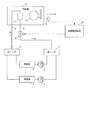
以下、本発明の実施の形態について図面を参照して説明する。図1は本発明の実施の形態に係る空調制御システムの構成を示すブロック図である。
図1において、1は冷水や温水等の熱媒を生成する熱源機、2は熱源機1が生成する冷温水を搬送するポンプ、3は複数の熱源機1からの冷温水を混合する往ヘッダ、4は往水管路、5は往ヘッダ3から往水管路4を介して送られてくる冷温水の供給を受ける空調機、6は還水管路、7は空調機5において熱交換され還水管路6を介して送られてくる冷温水が戻される還ヘッダ、8は往ヘッダ3から空調機5に供給される冷温水の流量を制御するバルブ、9は空調機5から送り出された給気の温度を計測する給気温度センサ、10は空調制御装置、11は空調機5のコイル、12は送風機である。
Hereinafter, embodiments of the present invention will be described with reference to the drawings. FIG. 1 is a block diagram showing a configuration of an air conditioning control system according to an embodiment of the present invention.
In FIG. 1, 1 is a heat source device that generates a heat medium such as cold water or hot water, 2 is a pump that conveys cold / hot water generated by the
ポンプ2により圧送され熱源機1により熱量が付加された熱媒は、往ヘッダ3において混合され、往水管路4を介して空調機5へ供給され、空調機5を通過して還水管路6により還水として還ヘッダ7に至り、再びポンプ2によって圧送される。このように、熱媒は以上の経路を循環する。例えば、熱源機1を冷凍機とした場合、熱媒は冷水であり、熱源機1を加熱機とした場合、熱媒は温水である。
The heat medium pumped by the
空調機5は、空調制御エリアとなる室内から空調制御システムに戻る空気(還気)と外気との混合気を、冷温水が通過するコイル11によって冷却または加熱し、冷却または加熱した給気を送風機12によって空調制御エリアとなる室内に送り込む。
The
本実施の形態は、バルブ8が流量計測機能を備え、空調制御装置10の操作量出力を受けて、この操作量出力に見合った流量を演算し、計測したバルブ通過流量が演算した流量と一致するように自身の開度を調節することを特徴としている。
図2はバルブ8の構成例を示すブロック図である。バルブ8は、空調機5を通過した冷温水が流入する流路を形成する弁箱80と、流路を開閉する弁体81と、流路を通過する冷温水の流量を計測する流量センサ(流量計測手段)82と、空調制御装置10から出力された操作量を流量に換算する流量換算部83と、流量換算部83が換算した流量値と流量センサ82によって計測された流量値に基づいて弁体81の開度を調節する開度調節部84とを有する。
流量センサ82の例としては、センサ部に流路抵抗を設け、流路前後圧力を計測して差圧から流量を演算する差圧式(オリフィス式等)流量センサや、挿入部の電磁場が流体の流れによって生じる偏差を検出する電磁式流量センサなどがある。
In the present embodiment, the
FIG. 2 is a block diagram showing a configuration example of the
Examples of the
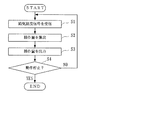
以下、本実施の形態の空調制御システムの動作について説明する。図3は空調制御装置10の動作を示すフローチャート、図4はバルブ8の動作を示すフローチャートである。
まず、空調制御装置10は、給気温度センサ9によって計測された給気温度を示す給気温度信号を受信する(図3ステップS1)。
Hereinafter, the operation of the air conditioning control system of the present embodiment will be described. FIG. 3 is a flowchart showing the operation of the air
First, the air-
そして、空調制御装置10は、給気温度センサ9によって計測された給気温度がオペレータ又は室内の居住者によって設定された温度設定値と一致するように空調機5を制御する。すなわち、空調制御装置10は、温度設定値と給気温度との偏差に基づいて、例えばPID演算によって操作量を算出し(ステップS2)、算出した操作量をバルブ8に出力する(ステップS3)。
And the air-
以上のような図3に示す処理が、空調制御システムが動作停止するまで(図3ステップS4においてYES)、繰り返し行われる。
なお、湿度センサ(不図示)によって給気の湿度を計測し、空調制御装置10が湿度設定値と現在の給気湿度との偏差に基づいて操作量を算出するようにしてもよい。
The process shown in FIG. 3 as described above is repeated until the air conditioning control system stops operating (YES in step S4 in FIG. 3).
The humidity of the supply air may be measured by a humidity sensor (not shown), and the air
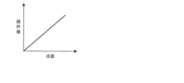
一方、バルブ8の流量換算部83は、空調制御装置10から出力された操作量を示す操作量信号を受信する(図4ステップS10)。そして、流量換算部83は、受信した操作量を流量値に換算する(ステップS11)。流量換算部83の内部には、図5に示すような操作量と流量との関係が例えばテーブルや数式の形で予め登録されている。流量換算部83は、この予め登録された関係に基づいて操作量から流量を演算する。
空調機5等の負荷機器の設計最大流量は、バルブ8が組み込まれる負荷機器の容量、空調をする空間の負荷容量から計算される。この設計最大流量値を操作量100%に割り当てる。そして、操作量と負荷機器の設計流量との関係を示す関数(流量特性)が図5に示すような直線的な関係にあるものとし、前記設計最大流量値と操作量が0%のときの流量値0とを用いて関数を求め、この関数を流量換算部83内の記憶部に予め登録しておけばよい。
On the other hand, the flow
The design maximum flow rate of the load equipment such as the
バルブ8の流量センサ82は、流路を通過する冷温水の流量(バルブ通過流量)を計測し、開度調節部84は、流量センサ82によって計測されたバルブ通過流量を示す流量信号を受信する(ステップS12)。そして、開度調節部84は、流量センサ82によって計測されたバルブ通過流量の値が流量換算部83によって換算された流量値と一致するように弁体81の開度を調節する(ステップS13)。
以上のような図4に示す処理が、空調制御システムが動作停止するまで(図4ステップS14においてYES)、繰り返し行われる。
The
The process shown in FIG. 4 as described above is repeated until the air conditioning control system stops operating (YES in step S14 in FIG. 4).
こうして、本実施の形態では、バルブ8が空調制御装置10の操作量出力に見合った流量を演算し、計測したバルブ通過流量が演算した流量と一致するように弁体81の開度を自身で調節することにより、空調機5を流れる冷温水の流量を適切に調節することができる。これにより、本実施の形態では、過大な流量による制御のハンチングと熱源機1の運転効率の悪化を劇的に改善することができ、より良い空調制御を行うことができる。
Thus, in the present embodiment, the
なお、本実施の形態で説明した空調制御装置10は、CPU、記憶装置およびインタフェースを備えたコンピュータとこれらのハードウェア資源を制御するプログラムによって実現することができる。同様に、バルブ8の流量換算部83と開度調節部84とは、コンピュータとプログラムによって実現することができる。これらのコンピュータのCPUは、それぞれの記憶装置に格納されたプログラムに従って、実施の形態で説明した処理を実行する。
In addition, the air-
また、本実施の形態では、流量制御バルブの適用例として空調制御システムを例に挙げて説明したが、これに限るものではなく、流量制御バルブを用いて流体の流量を制御するシステムであれば同様に適用することができる。 In this embodiment, an air conditioning control system has been described as an example of application of the flow control valve. However, the present invention is not limited to this, and any system that controls the flow rate of fluid using the flow control valve may be used. The same can be applied.
本発明は、流量制御バルブに適用することができる。 The present invention can be applied to a flow control valve.
1…熱源機、2…ポンプ、3…往ヘッダ、4…往水管路、5…空調機、6…還水管路、7…還ヘッダ、8…バルブ、9…給気温度センサ、10…空調制御装置、11…コイル、12…送風機、80…弁箱、81…弁体、82…流量センサ、83…流量換算部、84…開度調節部。
DESCRIPTION OF
Claims (2)
制御装置から出力された操作量を流量に換算する流量換算手段と、
前記流路を通過する流体の流量を計測する流量計測手段と、
この流量計測手段によって計測された通過流量が前記流量換算手段によって換算された流量と一致するように前記弁体の開度を調節する開度調節手段とを備えることを特徴とする流量制御バルブ。 A flow control valve comprising a valve body for opening and closing a flow path into which a fluid flows, and capable of adjusting the flow rate of the fluid according to the opening of the valve body,
Flow rate conversion means for converting the operation amount output from the control device into a flow rate;
Flow rate measuring means for measuring the flow rate of the fluid passing through the flow path;
A flow rate control valve comprising: an opening degree adjusting unit that adjusts an opening degree of the valve body so that a passing flow rate measured by the flow rate measuring unit matches a flow rate converted by the flow rate converting unit.
制御装置から出力された操作量を流量に換算する流量換算手順と、
前記流路を通過する流体の流量を計測する流量計測手順と、
この流量計測手順によって計測された通過流量が前記流量換算手順によって換算された流量と一致するように前記弁体の開度を調節する開度調節手順とを備えることを特徴とする流量制御方法。 In a flow control valve provided with a valve body for opening and closing a flow path into which a fluid flows, a flow control method for controlling the flow rate of the fluid by adjusting the opening of the valve body,
A flow rate conversion procedure for converting the operation amount output from the control device into a flow rate;
A flow rate measurement procedure for measuring the flow rate of the fluid passing through the flow path;
A flow rate control method comprising: an opening degree adjustment procedure for adjusting an opening degree of the valve body so that a passage flow rate measured by the flow rate measurement procedure matches a flow rate converted by the flow rate conversion procedure.
Priority Applications (4)
| Application Number | Priority Date | Filing Date | Title |
|---|---|---|---|
| JP2007192428A JP2009031866A (en) | 2007-07-24 | 2007-07-24 | Flow control valve and flow control method |
| CNA200810126531XA CN101354801A (en) | 2007-07-24 | 2008-06-24 | Flow control valve and flow control method |
| TW097125116A TW200907619A (en) | 2007-07-24 | 2008-07-03 | Flow control valve and flow control method |
| KR1020080067377A KR20090010889A (en) | 2007-07-24 | 2008-07-11 | Flow control valve and flow control method |
Applications Claiming Priority (1)
| Application Number | Priority Date | Filing Date | Title |
|---|---|---|---|
| JP2007192428A JP2009031866A (en) | 2007-07-24 | 2007-07-24 | Flow control valve and flow control method |
Publications (1)
| Publication Number | Publication Date |
|---|---|
| JP2009031866A true JP2009031866A (en) | 2009-02-12 |
Family
ID=40307600
Family Applications (1)
| Application Number | Title | Priority Date | Filing Date |
|---|---|---|---|
| JP2007192428A Pending JP2009031866A (en) | 2007-07-24 | 2007-07-24 | Flow control valve and flow control method |
Country Status (4)
| Country | Link |
|---|---|
| JP (1) | JP2009031866A (en) |
| KR (1) | KR20090010889A (en) |
| CN (1) | CN101354801A (en) |
| TW (1) | TW200907619A (en) |
Cited By (7)
| Publication number | Priority date | Publication date | Assignee | Title |
|---|---|---|---|---|
| JP2011106692A (en) * | 2009-11-12 | 2011-06-02 | Fujitsu Ltd | Air conditioning system |
| KR101266107B1 (en) | 2011-10-25 | 2013-05-27 | 엘지전자 주식회사 | Air conditioner and Control method of the same |
| WO2015001976A1 (en) * | 2013-07-01 | 2015-01-08 | 株式会社日立製作所 | Heat source system |
| US9109817B2 (en) | 2011-10-25 | 2015-08-18 | Lg Electronics Inc. | Air conditioner and method of operating an air conditioner |
| CN105066358A (en) * | 2015-08-17 | 2015-11-18 | 烟台荏原空调设备有限公司 | Method and system for automatically adjusting temperature of air conditioning unit |
| CN113374880A (en) * | 2021-06-15 | 2021-09-10 | 上海市计量测试技术研究院 | Device and method for adjusting flow velocity of ozonized gas in ozone aging box |
| US11199350B2 (en) | 2017-09-22 | 2021-12-14 | Mitsubishi Electric Corporation | Air-conditioning apparatus with regulated flow of a heat medium |
Families Citing this family (9)
| Publication number | Priority date | Publication date | Assignee | Title |
|---|---|---|---|---|
| TWI423363B (en) * | 2009-10-26 | 2014-01-11 | Nat Univ Chin Yi Technology | Testing platform and method for properties of process cooling machine |
| CA2811775A1 (en) | 2010-11-17 | 2012-05-24 | Belimo Holding Ag | Device and method for controlling opening of a valve in an hvac system |
| US9733649B2 (en) * | 2012-05-31 | 2017-08-15 | Fujikin Incorporated | Flow control system with build-down system flow monitoring |
| KR20150108578A (en) * | 2014-03-18 | 2015-09-30 | 가부시키가이샤 어드밴티스트 | Temperature control apparatus and test system |
| CN104500811A (en) * | 2014-12-10 | 2015-04-08 | 西南铝业(集团)有限责任公司 | Emulsion flow rate control system |
| CN109289707A (en) * | 2018-11-22 | 2019-02-01 | 云南驰宏国际锗业有限公司 | The feeding mechanism and its control system of a kind of germanium tetrachloride hydrolysis device and application |
| CN110274670B (en) * | 2019-06-18 | 2020-08-14 | 上海市供水水表强制检定站有限公司 | Correction method and system for flow control valve of water meter |
| TWI774227B (en) * | 2020-02-21 | 2022-08-11 | 日商富士金股份有限公司 | Flow rate control device, control method thereof and control program thereof |
| CN112068610B (en) * | 2020-09-23 | 2022-10-18 | 杭州振华仪表有限公司 | Pressure balance flowmeter, flow control system and flow control method |
Citations (5)
| Publication number | Priority date | Publication date | Assignee | Title |
|---|---|---|---|---|
| JPH0784649A (en) * | 1993-09-14 | 1995-03-31 | Kitz Corp | Flow rate control unit having both of constant flow rate function and variable flow rate function |
| JPH11211191A (en) * | 1998-01-30 | 1999-08-06 | Yamatake Corp | Air conditioning control system |
| JPH11353033A (en) * | 1998-06-05 | 1999-12-24 | Japan Organo Co Ltd | Temperature control system of indirect heating type |
| JP2001147723A (en) * | 2000-09-07 | 2001-05-29 | Hitachi Metals Ltd | Method for controlling flow rate |
| JP2001182971A (en) * | 1999-12-24 | 2001-07-06 | Hitachi Ltd | Air conditioning system and its control method |
-
2007
- 2007-07-24 JP JP2007192428A patent/JP2009031866A/en active Pending
-
2008
- 2008-06-24 CN CNA200810126531XA patent/CN101354801A/en active Pending
- 2008-07-03 TW TW097125116A patent/TW200907619A/en unknown
- 2008-07-11 KR KR1020080067377A patent/KR20090010889A/en active Search and Examination
Patent Citations (5)
| Publication number | Priority date | Publication date | Assignee | Title |
|---|---|---|---|---|
| JPH0784649A (en) * | 1993-09-14 | 1995-03-31 | Kitz Corp | Flow rate control unit having both of constant flow rate function and variable flow rate function |
| JPH11211191A (en) * | 1998-01-30 | 1999-08-06 | Yamatake Corp | Air conditioning control system |
| JPH11353033A (en) * | 1998-06-05 | 1999-12-24 | Japan Organo Co Ltd | Temperature control system of indirect heating type |
| JP2001182971A (en) * | 1999-12-24 | 2001-07-06 | Hitachi Ltd | Air conditioning system and its control method |
| JP2001147723A (en) * | 2000-09-07 | 2001-05-29 | Hitachi Metals Ltd | Method for controlling flow rate |
Cited By (9)
| Publication number | Priority date | Publication date | Assignee | Title |
|---|---|---|---|---|
| JP2011106692A (en) * | 2009-11-12 | 2011-06-02 | Fujitsu Ltd | Air conditioning system |
| KR101266107B1 (en) | 2011-10-25 | 2013-05-27 | 엘지전자 주식회사 | Air conditioner and Control method of the same |
| US9109817B2 (en) | 2011-10-25 | 2015-08-18 | Lg Electronics Inc. | Air conditioner and method of operating an air conditioner |
| US9958188B2 (en) | 2011-10-25 | 2018-05-01 | Lg Electronics Inc. | Air conditioner and method of operating an air conditioner |
| WO2015001976A1 (en) * | 2013-07-01 | 2015-01-08 | 株式会社日立製作所 | Heat source system |
| JP2015010789A (en) * | 2013-07-01 | 2015-01-19 | 株式会社日立製作所 | Heat source system |
| CN105066358A (en) * | 2015-08-17 | 2015-11-18 | 烟台荏原空调设备有限公司 | Method and system for automatically adjusting temperature of air conditioning unit |
| US11199350B2 (en) | 2017-09-22 | 2021-12-14 | Mitsubishi Electric Corporation | Air-conditioning apparatus with regulated flow of a heat medium |
| CN113374880A (en) * | 2021-06-15 | 2021-09-10 | 上海市计量测试技术研究院 | Device and method for adjusting flow velocity of ozonized gas in ozone aging box |
Also Published As
| Publication number | Publication date |
|---|---|
| KR20090010889A (en) | 2009-01-30 |
| TW200907619A (en) | 2009-02-16 |
| CN101354801A (en) | 2009-01-28 |
Similar Documents
| Publication | Publication Date | Title |
|---|---|---|
| JP2009031866A (en) | Flow control valve and flow control method | |
| RU2660721C2 (en) | Device and method for controlling opening of valve in hvac system | |
| RU2573378C2 (en) | Device and method of valve opening control for hvac system | |
| JP6324628B2 (en) | Heat pump utilization system control device and heat pump utilization system including the same | |
| TWI407060B (en) | Air conditioner controlling apparatus and method | |
| KR101805334B1 (en) | Heat source device | |
| JP6609697B2 (en) | Heat source system and control method of heat source system | |
| JP5501282B2 (en) | HEAT PUMP SYSTEM AND HEAT PUMP SYSTEM CONTROL METHOD | |
| JP4814166B2 (en) | Information display device and information display method for flow control valve | |
| KR20160051596A (en) | Air-conditioning system | |
| US11221150B2 (en) | System and method of controlling a mixing valve of a heating system | |
| US10480826B2 (en) | System and method of controlling a mixing valve of a heating system | |
| JP2010243002A (en) | Air conditioning system | |
| WO2019193649A1 (en) | Control device, outdoor unit, and air conditioning system | |
| JP2009243829A (en) | Air conditioner | |
| JPH11211190A (en) | Outdoor air cooling air conditioning control system and air conditioning control device | |
| JP2009030822A (en) | Flow rate control valve and flow rate control method | |
| US10684025B2 (en) | Method of controlling a fluid circulation system | |
| JP2009281666A (en) | Control method for hot water heating apparatus | |
| JP6890727B1 (en) | Air conditioning system and control method | |
| JP5216813B2 (en) | Control method for air conditioning system | |
| JP5102195B2 (en) | Temperature control device | |
| US20200340701A1 (en) | System and method for building climate control | |
| CN113639388A (en) | Method and device for controlling air conditioner air outlet in machine room, air conditioner and storage medium | |
| JP2000172301A (en) | Control mode switch device and temperature control system |
Legal Events
| Date | Code | Title | Description |
|---|---|---|---|
| A621 | Written request for application examination |
Free format text: JAPANESE INTERMEDIATE CODE: A621 Effective date: 20100315 |
|
| A977 | Report on retrieval |
Free format text: JAPANESE INTERMEDIATE CODE: A971007 Effective date: 20110803 |
|
| A131 | Notification of reasons for refusal |
Free format text: JAPANESE INTERMEDIATE CODE: A131 Effective date: 20110816 |
|
| A521 | Written amendment |
Free format text: JAPANESE INTERMEDIATE CODE: A523 Effective date: 20111012 |
|
| A131 | Notification of reasons for refusal |
Free format text: JAPANESE INTERMEDIATE CODE: A131 Effective date: 20120221 |
|
| A02 | Decision of refusal |
Free format text: JAPANESE INTERMEDIATE CODE: A02 Effective date: 20120626 |