JP2009018708A - Vehicle and control method therefor - Google Patents
Vehicle and control method therefor Download PDFInfo
- Publication number
- JP2009018708A JP2009018708A JP2007183167A JP2007183167A JP2009018708A JP 2009018708 A JP2009018708 A JP 2009018708A JP 2007183167 A JP2007183167 A JP 2007183167A JP 2007183167 A JP2007183167 A JP 2007183167A JP 2009018708 A JP2009018708 A JP 2009018708A
- Authority
- JP
- Japan
- Prior art keywords
- capacitor
- electric motor
- vehicle
- voltage
- motor
- Prior art date
- Legal status (The legal status is an assumption and is not a legal conclusion. Google has not performed a legal analysis and makes no representation as to the accuracy of the status listed.)
- Pending
Links
Images

Classifications
-
- Y—GENERAL TAGGING OF NEW TECHNOLOGICAL DEVELOPMENTS; GENERAL TAGGING OF CROSS-SECTIONAL TECHNOLOGIES SPANNING OVER SEVERAL SECTIONS OF THE IPC; TECHNICAL SUBJECTS COVERED BY FORMER USPC CROSS-REFERENCE ART COLLECTIONS [XRACs] AND DIGESTS
- Y02—TECHNOLOGIES OR APPLICATIONS FOR MITIGATION OR ADAPTATION AGAINST CLIMATE CHANGE
- Y02T—CLIMATE CHANGE MITIGATION TECHNOLOGIES RELATED TO TRANSPORTATION
- Y02T10/00—Road transport of goods or passengers
- Y02T10/60—Other road transportation technologies with climate change mitigation effect
- Y02T10/62—Hybrid vehicles
Abstract
Description
本発明は、車両およびその制御方法に関する。 The present invention relates to a vehicle and a control method thereof.
従来、この種の車両としては、内燃機関とモータと駆動輪に連結されたトランスミッションとを直結すると共にモータと電力のやり取りが可能なキャパシタを備えるものが提案されている(例えば、特許文献1参照)。
一般に、こうした車両では、キャパシタの端子間電圧が低いと、キャパシタに蓄えた電力を用いてモータを駆動する際にモータから十分なパワーを出力することができなくなる。したがって、このことを考慮して、こうした車両、特に、レース用の車両では、レースにおけるセーフティーカーによる先導時など前方の車両の追い越しが禁止されているときに、その追い越し禁止が解除されたときの車両の加速を得るための準備をしておくことが望まれる。 In general, in such a vehicle, when the voltage across the terminals of the capacitor is low, sufficient power cannot be output from the motor when the motor is driven using the electric power stored in the capacitor. Therefore, in consideration of this, in such vehicles, especially racing vehicles, when overtaking of the preceding vehicle is prohibited, such as when leading by a safety car in a race, when the overtaking prohibition is canceled It is desirable to be prepared to obtain vehicle acceleration.
本発明の車両およびその制御方法は、前方の車両の追い越しを禁止する追い越し禁止モードが設定された後にその追い越し禁止モードが解除されてドライバーが車両を加速させたいときにその要求に対処できるようにすることを主目的とする。 The vehicle and the control method thereof according to the present invention can cope with the request when the driver wants to accelerate the vehicle by releasing the overtaking prohibition mode after the overtaking prohibition mode for prohibiting overtaking of the vehicle ahead is set. The main purpose is to do.
本発明の車両およびその制御方法は、上述の主目的を達成するために以下の手段を採った。 The vehicle and the control method thereof according to the present invention employ the following means in order to achieve the main object described above.
本発明の車両は、
走行用の動力を出力可能な内燃機関と、走行用の動力を入出力可能な電動機と、前記電動機と電力のやり取りが可能なキャパシタと、を備える車両であって、
前記キャパシタの端子間電圧であるキャパシタ電圧を検出するキャパシタ電圧検出手段と、
前方の車両の追い越しを禁止する追い越し禁止モードが設定されている追い越し禁止モード時には、前記検出されるキャパシタ電圧が前記追い越し禁止モードが設定されていない通常走行時の前記キャパシタの使用下限電圧として予め定められた第1下限電圧よりも高い第2下限電圧以上となると共に運転者の操作に基づいて走行するよう前記内燃機関と前記電動機とを制御する制御手段と、
を備えることを要旨とする。
The vehicle of the present invention
A vehicle comprising an internal combustion engine capable of outputting power for traveling, an electric motor capable of inputting / outputting power for traveling, and a capacitor capable of exchanging electric power with the electric motor,
Capacitor voltage detecting means for detecting a capacitor voltage which is a voltage between terminals of the capacitor;
In the overtaking prohibition mode in which the overtaking prohibition mode for prohibiting overtaking of the vehicle ahead is set, the detected capacitor voltage is determined in advance as the lower limit voltage for use of the capacitor during normal driving in which the overtaking prohibition mode is not set. Control means for controlling the internal combustion engine and the electric motor to travel on the basis of a driver's operation while being equal to or higher than a second lower limit voltage higher than the first lower limit voltage.
It is a summary to provide.
この本発明の車両では、前方の車両の追い越しを禁止する追い越し禁止モードが設定されている追い越し禁止モード時には、キャパシタの端子間電圧であるキャパシタ電圧が追い越し禁止モードが設定されていない通常走行時のキャパシタの使用下限電圧として予め定められた第1下限電圧よりも高い第2下限電圧以上となると共に運転者の操作に基づいて走行するよう内燃機関と電動機とを制御する。これにより、通常走行時に比してキャパシタの電圧を比較的高い状態にしておくことができる。この結果、その後に追い越し禁止モードが解除されてドライバーが車両を加速させたいときに、電動機にその性能を十分に発揮させる電力を供給することができ、ドライバーの加速要求に対処することができる。ここで、「運転者の操作」には、アクセル操作やブレーキ操作が含まれる。 In the vehicle according to the present invention, during the overtaking prohibition mode in which the overtaking prohibition mode for prohibiting overtaking of the vehicle ahead is set, the capacitor voltage, which is the voltage between the terminals of the capacitor, during normal driving in which the overtaking prohibition mode is not set. The internal combustion engine and the electric motor are controlled so as to run on the basis of the driver's operation while being equal to or higher than a second lower limit voltage higher than a predetermined first lower limit voltage as a use lower limit voltage of the capacitor. As a result, the voltage of the capacitor can be kept relatively high as compared with normal driving. As a result, when the overtaking prohibition mode is subsequently canceled and the driver wants to accelerate the vehicle, the electric power that allows the motor to fully exhibit its performance can be supplied, and the driver's acceleration request can be dealt with. Here, “driver's operation” includes accelerator operation and brake operation.
こうした本発明の車両において、前記制御手段は、前記追い越し禁止モード時に前記キャパシタ電圧が前記第2下限電圧未満のときには、運転者の操作に拘わらず前記キャパシタの充電が行なわれるよう前記電動機を制御する手段であるものとすることもできる。こうすれば、キャパシタ電圧が第2下限電圧を超えて大きく低下するのを抑制することができる。 In such a vehicle of the present invention, the control means controls the electric motor so that the capacitor is charged regardless of the operation of the driver when the capacitor voltage is lower than the second lower limit voltage in the overtaking prohibition mode. It can also be a means. In this way, it is possible to suppress the capacitor voltage from greatly decreasing beyond the second lower limit voltage.
また、本発明の車両において、前記制御手段は、前記追い越し禁止モード時に前記キャパシタ電圧が前記第2下限電圧以上のときには、アクセル操作が行なわれていないとき又はブレーキ操作が行なわれているときに前記キャパシタの充電が行なわれるよう前記電動機を制御する手段であるものとすることもできる。また、前記制御手段は、前記追い越し禁止モード時に前記キャパシタ電圧が前記第2下限電圧以上のときには、アクセル操作が行なわれているときには前記キャパシタの充電を行なわないものとすることができる。 In the vehicle of the present invention, the control means may be configured such that when the capacitor voltage is equal to or higher than the second lower limit voltage in the overtaking prohibition mode, the accelerator operation is not performed or the brake operation is performed. It may be a means for controlling the electric motor so that the capacitor is charged. The control means may not charge the capacitor when an accelerator operation is being performed when the capacitor voltage is equal to or higher than the second lower limit voltage in the overtaking prohibition mode.
さらに、本発明の車両において、前記追い越し禁止モード時にブレーキ操作が行なわれているときには、前記通常走行時に比して前記電動機から出力される回生トルクが大きくなるよう前記電動機を制御する手段であるものとすることもできる。こすうれば、通常走行時に比してキャパシタに充電される電力を大きくすることができる。 Further, in the vehicle of the present invention, when the brake operation is performed in the overtaking prohibition mode, the vehicle is a means for controlling the electric motor so that the regenerative torque output from the electric motor is larger than that during the normal traveling. It can also be. By rubbing, it is possible to increase the electric power charged in the capacitor as compared with normal driving.
あるいは、本発明の車両において、前記電動機は、前記内燃機関の出力軸に取り付けられてなり、前記制御手段は、ブレーキ操作が行なわれていないときに前記キャパシタの充電を行なうときには、前記内燃機関から出力される動力の一部を用いて前記電動機により発電が行なわれるよう該電動機を制御する手段である、ものとすることもできる。また、本発明の車両において、前記電動機は、前記内燃機関の出力軸に取り付けられた第1の電動機と前記内燃機関の出力軸が接続された車軸である第1の車軸とは異なる第2の車軸に取り付けられた第2の電動機とをを有し、前記制御手段は、ブレーキ操作が行なわれていないときに前記キャパシタの充電を行なうときには前記内燃機関から出力される動力の一部を用いて前記第1の電動機により発電が行なわれるよう該第1の電動機を制御し、ブレーキ操作が行なわれているときに前記キャパシタの充電を行なうときには前記第2の電動機から前記車両に制動力が作用するよう該第2の電動機を制御する手段であるものとすることもできる。ここで、「第2の電動機」は、前記第2の車軸に取り付けられた車輪に直接動力を出力するインホイールモータである、ものとすることもできる。 Alternatively, in the vehicle of the present invention, the electric motor is attached to an output shaft of the internal combustion engine, and the control means is configured to charge the capacitor when the brake operation is not performed. It may be a means for controlling the electric motor so that electric power is generated by the electric motor using a part of the output power. Further, in the vehicle of the present invention, the electric motor is different from a first axle that is an axle connected to the first electric motor attached to the output shaft of the internal combustion engine and the output shaft of the internal combustion engine. A second electric motor attached to the axle, and the control means uses a part of the power output from the internal combustion engine when charging the capacitor when the brake operation is not performed. When the first motor is controlled so that power is generated by the first motor, and the capacitor is charged when a braking operation is performed, a braking force acts on the vehicle from the second motor. The second electric motor can be controlled as described above. Here, the “second electric motor” may be an in-wheel motor that directly outputs power to a wheel attached to the second axle.
本発明の車両において、前記制御手段は、セーフティーカーによる先導時に用いられるスイッチがオンされているときに前記追い越し禁止モードが設定されているとして制御する手段であるものとすることもできる。また、前記電動機と電力のやり取りが可能な機器として前記キャパシタのみを搭載するものとすることもできる。 In the vehicle of the present invention, the control means may be means for controlling that the overtaking prohibition mode is set when a switch used for leading by a safety car is turned on. Further, only the capacitor can be mounted as a device capable of exchanging electric power with the electric motor.
本発明の車両の制御方法は、
走行用の動力を出力可能な内燃機関と、走行用の動力を入出力可能な電動機と、前記電動機と電力のやり取りが可能なキャパシタと、を備える車両の制御方法であって、
前方の車両の追い越しを禁止する追い越し禁止モードが設定されている追い越し禁止モード時には、前記キャパシタの端子間電圧であるキャパシタ電圧が前記追い越し禁止モードが設定されていない通常走行時の前記キャパシタの使用下限電圧として予め定められた第1下限電圧よりも高い第2下限電圧以上となると共に運転者の操作に基づいて走行するよう前記内燃機関と前記電動機とを制御する、
ことを特徴とする。
The vehicle control method of the present invention includes:
A vehicle control method comprising: an internal combustion engine capable of outputting driving power; an electric motor capable of inputting / outputting driving power; and a capacitor capable of exchanging electric power with the electric motor,
In the overtaking prohibition mode in which the overtaking prohibition mode for prohibiting overtaking of the vehicle ahead is set, the capacitor voltage, which is the voltage between the terminals of the capacitor, is the lower limit of use of the capacitor during normal driving in which the overtaking prohibition mode is not set Controlling the internal combustion engine and the electric motor so as to travel based on a driver's operation while being equal to or higher than a second lower limit voltage higher than a first lower limit voltage predetermined as a voltage;
It is characterized by that.
この本発明の車両の制御方法では、前方の車両の追い越しを禁止する追い越し禁止モードが設定されている追い越し禁止モード時には、キャパシタの端子間電圧であるキャパシタ電圧が追い越し禁止モードが設定されていない通常走行時のキャパシタの使用下限電圧として予め定められた第1下限電圧よりも高い第2下限電圧以上となると共に運転者の操作に基づいて走行するよう内燃機関と電動機とを制御する。これにより、通常走行時に比してキャパシタの電圧を比較的高い状態にしておくことができる。この結果、その後に追い越し禁止モードが解除されてドライバーが車両を加速させたいときに、電動機にその性能を十分に発揮させる電力を供給することができ、ドライバーの加速要求に対処することができる。ここで、「運転者の操作」には、アクセル操作やブレーキ操作が含まれる。 In the vehicle control method of the present invention, in the overtaking prohibition mode in which the overtaking prohibition mode for prohibiting overtaking of the vehicle ahead is set, the capacitor voltage, which is the voltage between the terminals of the capacitor, is not set in the overtaking prohibition mode. The internal combustion engine and the electric motor are controlled so as to travel on the basis of the driver's operation while being equal to or higher than a second lower limit voltage that is higher than a predetermined first lower limit voltage. As a result, the voltage of the capacitor can be kept relatively high as compared with normal driving. As a result, when the overtaking prohibition mode is subsequently canceled and the driver wants to accelerate the vehicle, the electric power that allows the motor to fully exhibit its performance can be supplied, and the driver's acceleration request can be dealt with. Here, “driver's operation” includes accelerator operation and brake operation.
次に、本発明を実施するための最良の形態を実施例を用いて説明する。 Next, the best mode for carrying out the present invention will be described using examples.
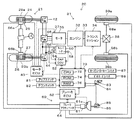
図1は、本発明の一実施例としてのレース用に開発されたハイブリッド自動車20の構成の概略を示す構成図である。実施例のハイブリッド自動車20は、左右前輪29a,29bに取り付けられた二つの前輪用モータ24,26を有する前輪系21と、エンジン32とエンジン32のクランクシャフト33に取り付けられたモータ36とからの動力をトランスミッション34とデファレンシャルギヤ38とを介して左右後輪39a,39bに出力する後輪系31と、前輪用モータ24,26やモータ36と電力のやり取りを行なうキャパシタ50と、左右前輪29a,29bや左右後輪39a,39bに取り付けられたホイールシリンダ66a,66b,68a,68bに油圧を作用させることにより制動トルクを付与する電子制御式油圧ブレーキユニット(以下、「ECB」という。)60と、ハイブリッド自動車20の全体をコントロールするメイン電子制御ユニット70とを備える。
FIG. 1 is a configuration diagram showing an outline of a configuration of a
前輪用モータ24,26は、同期発電電動機や減速機、ハブベアリング等を一体化したいわゆるインホイールモータとして構成された互いに同一のものであり、インバータ42,44を介してキャパシタ50と電力のやりとりを行なう。すなわち、前輪用モータ24,26は、左右前輪29a,29bに対して制動力や駆動力を左右独立に分配して出力可能な動力ユニットとして機能する。前輪用モータ24,26は、モータ用電子制御ユニット(以下、「モータECU」という。)40により駆動制御を受けている。
The
エンジン32は、ガソリンまたは軽油等の炭化水素系の燃料により動力を出力する内燃機関であり、エンジン32の運転状態を検出する各種センサから信号を入力するメイン電子制御ユニット70により燃料噴射量や点火時期、吸入空気量等の制御を受けている。
The
トランスミッション34は、例えば油圧駆動の6速の変速機として構成されており、ドライバーによるアップスイッチ81やダウンスイッチ82の操作に基づく信号を入力するメイン電子制御ユニット70によりアップシフトやダウンシフトが行なわれるよう変速制御される。
The
モータ36は、発電機として作動することができると共に電動機として作動可能な周知の同期発電電動機として構成されており、インバータ46を介してキャパシタ50と電力のやりとりを行なう。モータ36は、前輪用モータ24,26と同様に、モータECU40により駆動制御を受けている。モータECU40には、前輪用モータ24,26やモータ36を駆動制御するために必要な信号、例えば前輪用モータ24,26やモータ36の回転子の回転位置を検出する回転位置検出センサ25,27,37からの信号や図示しない電流センサにより検出される前輪用モータ24,26やモータ36に印加される相電流等が入力されており、モータECU40からは、インバータ42,44,46へのスイッチング制御信号が出力される。インバータ42,44,46は、それぞれ6つのスイッチング素子と6つのダイオードとからなる周知のインバータ回路として構成されており、正極母線および負極母線がキャパシタ50の入出力端子に接続されている。モータECU40は、メイン電子制御ユニット70と通信しており、メイン電子制御ユニット70からの制御信号によって前輪用モータ24,26やモータ36を駆動制御すると共に必要に応じて前輪用モータ24,26やモータ36の運転状態に関するデータをメイン電子制御ユニット70に出力する。なお、モータECU40は、回転位置検出センサ25,27,37からの信号に基づいて前輪用モータ24,26やモータ36の回転数Nfl,Nfr,Nmも演算している。
The motor 36 is configured as a well-known synchronous generator motor that can operate as a generator and can operate as an electric motor, and exchanges electric power with the
キャパシタ50は、例えば電気二重層キャパシタとして構成されており、キャパシタ用電子制御ユニット(以下、「キャパシタECU」という。)52により充放電の制御が行なわれている。キャパシタECU52には、キャパシタ50の端子間に取り付けられた電圧センサ54により検出されるキャパシタ50の端子間電圧Vcapやキャパシタ50からの電力ラインに取り付けられた電流センサ56により検出されるキャパシタ50を流れる電流Icap,キャパシタ50に取り付けられた温度センサ58により検出されるキャパシタ50の温度Tcapなどが入力されている。キャパシタECU52は、メイン電子制御ユニット70と通信しており、必要に応じてメイン電子制御ユニット70に充放電に必要な制御信号を送信したり、キャパシタ50の状態に関するデータをメイン電子制御ユニット70に出力する。
The
ECB60は、ブレーキペダル85の踏み込みにより加圧されるマスタシリンダ61と、マスタシリンダ61の圧力(ブレーキ踏力)に応じて車両に作用させるべき制動力のうちのECB60の分担割合に応じた制動トルクが左右前輪29a,29bや左右後輪39a,39bに作用するようにホイールシリンダ66a,66b,68a,68bへの油圧を調整するブレーキアクチュエータ64と、ブレーキアクチュエータ64を駆動制御するブレーキ用電子制御ユニット(以下、「ブレーキECU」という。)62と、を備える。ブレーキECU62には、マスタシリンダ61に取り付けられたマスタシリンダ圧センサ61aにより検出されるマスタシリンダ圧(ブレーキ踏力Fb)や左右前輪29a,29bおよび左右後輪39a,39bに設けられた図示しない車輪速センサからの車輪速などが入力されており、ブレーキECU62からはブレーキアクチュエータ64への駆動信号が出力されている。ブレーキECU62は、メイン電子制御ユニット70と通信しており、メイン電子制御ユニット70からの制御信号によって左右前輪29a,29bや左右後輪39a,39bに制動トルクを作用させると共に必要に応じてECB60の状態に関するデータをメイン電子制御ユニット70に出力する。
The
メイン電子制御ユニット70は、CPU72を中心とするマイクロプロセッサとして構成されており、CPU72の他に処理プログラムを記憶するROM74と、データを一時的に記憶するRAM76と、図示しない入出力ポートおよび通信ポートとを備える。メイン電子制御ユニット70には、ステアリングに取り付けられてトランスミッション34のアップシフトやダウンシフトを指示するアップスイッチ81やダウンスイッチ82からの信号やアクセルペダル83の踏み込み量を検出するアクセルペダルポジションセンサ84からのアクセル開度Acc、ブレーキペダル85の踏み込み量を検出するブレーキペダルポジションセンサ86からのブレーキペダルポジションBP,セーフティーカーモードを設定するためのセーフティーカーモードスイッチ87からのオンオフ信号,ピットインモードを設定するためのピットモードスイッチ88からのオンオフ信号などが入力ポートを介して入力されている。メイン電子制御ユニット70は、上述したように、モータECU40やキャパシタECU52,ブレーキECU62と通信ポートを介して接続されており、モータECU40やキャパシタECU52ブレーキECU62と各種制御信号やデータのやりとりを行なっている。
The main
こうして構成された実施例のハイブリッド自動車20は、アクセルペダル83の踏み込み量に応じてエンジン32の吸入空気量などを調整すると共にキャパシタ50に蓄えられた電力を用いてモータ36からトルク出力を行ない、ブレーキペダル85の踏み込み力(踏力)に応じたブレーキトルクをECB60と前輪用モータ24,26とから出力し、前輪用モータ24,26の回生トルクの出力により得られる回生電力をキャパシタ50に蓄える。実施例では、レース用の車両としてハイブリッド自動車20を構成しているため、キャパシタ50の制御としては、キャパシタ50の最大電圧(耐圧)Vmaxより1割〜2割程度低い電圧を上限電圧Vhiとしてキャパシタ50の入力制限を行ない、前輪用モータ24,26からの回生トルクの出力によりレース用のコースを走行したときにコースにおいて最も大きな出力が要求される箇所(例えば、長い直線の入口)の直前でキャパシタ50の電圧が上限電圧Vhiとなるようにコース毎に設定された最低電圧Vsetをキャパシタ50の下限電圧Vlowとして設定して出力制限を行なう。例えば、耐圧が900Vのキャパシタを用いた場合、上限電圧Vhiとしてはコースに無関係に750Vや800Vなどを用い、下限電圧VlowとしてはAコースでは500Vを用い、Bコースでは580Vを用いるなどとして運用するのである。このように下限電圧Vlowをコース毎に設定するのは、コース上で最もモータ36からの出力が要求される箇所で最大出力によりモータ36を駆動するためである。したがって、実施例のハイブリッド自動車20では、上限電圧Vhiと下限電圧Vlowとによって設定されるキャパシタ50の使用電圧範囲に基づくキャパシタ50の入出力制限Win,Woutを用いてモータ36や前輪用モータ24,26を駆動制御することになる。なお、キャパシタ50の入力制限Winの設定については後述する。
The
次に、こうして構成された実施例のハイブリッド自動車20の動作、特に、レース中にセーフティーカーが導入されてドライバーによりセーフティーカーモードスイッチ87がオンされたときの動作について説明する。図2は、実施例のハイブリッド用電子制御ユニット70により実行されるセーフティカーモード時制御ルーチンの一例を示すフローチャートである。このルーチンは、セーフティーカーモードスイッチ87がオンされているときに所定時間毎(例えば、数msec毎)に繰り返し実行される。
Next, the operation of the
セーフティーカーモード時制御ルーチンが実行されると、ハイブリッド用電子制御ユニット70のCPU72は、まず、アクセルペダルポジションセンサ84からのアクセル開度Accやブレーキ踏力Fb,前輪用モータ24,26やモータ36の回転数Nfr,Nfl,Nm,キャパシタ50の端子間電圧Vcap,キャパシタ50のセーフティカーモード時下限電圧Vlowscなど制御に必要なデータを入力する処理を実行する(ステップS100)。ここで、ブレーキ踏力Fbは、マスタシリンダ圧センサ61aにより検出されたものをブレーキECU62から通信により入力するものとした。また、前輪用モータ24,26やモータ36の回転数Nfr,Nfl,Nmは、回転位置検出センサ25,27,37により検出された信号に基づいて演算されたものをモータECU40から通信により入力するものとした。さらに、キャパシタ50の端子間電圧Vcapは、電圧センサ54により検出されたものをキャパシタECU52から通信により入力するものとした。セーフティーカーモード時下限電圧Vlowscは、セーフティーカーモードスイッチ87がオンされていないとき(通常のレース中、以下、このときを通常走行時という)のキャパシタ50の下限電圧Vlowに比して高い電圧(例えば、700Vなど)として定められている。
When the safety car mode control routine is executed, the
こうしてデータを入力すると、キャパシタ50の端子間電圧Vcapと上限電圧Vhiとに基づいてキャパシタ50の入力制限Winを設定する(ステップS105)。キャパシタ50の入力制限Winの設定は、実施例では、上限電圧Vhiから端子間電圧Vcapを減じた値が所定値(例えば上限電圧Vhiの5%)以上のときにはキャパシタ50の定格最大入力を入力制限Winとして設定し、上限電圧Vhiから端子間電圧Vcapを減じた値が所定値未満のときには端子間電圧Vcapが上限電圧Vhiに近づくほど小さくなるように、そしてキャパシタ50の端子間電圧Vcapが上限電圧Vhiに至ったときに値0になるよう入力制限Winを設定するものとした。
When the data is thus input, the input limit Win of the
続いて、キャパシタ50の端子間電圧Vcapをセーフティーカーモード時下限電圧Vlowscと比較すると共に(ステップS110)、ブレーキ踏力Fbが値0か否かを判定する(ステップ120,130)。ブレーキ踏力Fbが値0か否かの判定は、ドライバーによりブレーキペダル85が踏み込まれているか否かを判定するものである。キャパシタ50の端子間電圧Vcapがセーフティーカーモード時下限電圧Vlowsc以上でブレーキ踏力Fbが値0のときには、アクセル開度Accに基づいてエンジン32の吸入空気量制御や燃料噴射制御,点火制御などを行なって(ステップS140)、セーフティーカーモード時制御ルーチンを終了する。
Subsequently, the inter-terminal voltage Vcap of the
キャパシタ50の端子間電圧Vcapがセーフティーカーモード時下限電圧Vlowsc未満のときにブレーキ踏力Fbが値0のときには(ステップS110,S130)、キャパシタ50の目標充電パワーPcap*を設定する(ステップS150)。キャパシタ50の目標充電パワーPcap*は、例えば、固定値を用いるものとしたり、キャパシタ50の電圧Vcapとセーフティーカーモード時下限電圧Vlowscとの偏差が打ち消されるよう比例項や積分項を用いたフィードバック制御などにより設定するものとしたりすることができる。
When the brake pedal force Fb is 0 when the voltage Vcap between the terminals of the
続いて、設定したキャパシタ50の目標充電パワーPcap*をモータ36の回転数Nmで除してモータ36から出力すべき発電トルク(負のトルク)の仮の値としての仮発電トルクTmrtmpを計算すると共に(ステップS160)、キャパシタ50の入力制限Winをモータ36の回転数Nmで除してモータ36から出力してもよい最大発電トルク(負の値)としてのトルク制限Tmrminを計算し(ステップS170)、仮発電トルクTmrtmpとトルク制限Tmrminとのうち大きい方(絶対値としては小さい方)をモータ36のトルク指令Tmr*として設定すると共に設定したトルク指令Tmr*をモータECU40に送信し(ステップS180)、エンジン32を制御して(ステップS190)、セーフティーカーモード時制御ルーチンを終了する。トルク指令Tmr*を受信したモータECU40は、モータ36からトルク指令Tmr*に相当するトルクが出力されるようインバータ46のスイッチング素子をスイッチング制御する。この場合、モータ36により発電された電力がキャパシタ50に充電される。したがって、セーフティーカーモード時にある程度の時間に亘ってブレーキペダル85が踏み込まれないときでもキャパシタ50の電圧Vcapがセーフティーカーモード時下限電圧Vlowscを大きく下回るのを抑制しながら走行することができる。この結果、セーフティーカーモードスイッチ87がオフされてからドライバーによりアクセルペダル83が大きく踏み込まれたときにモータ36にその性能を十分に発揮させる電力を供給することができる。なお、この場合、エンジン32から出力される動力の一部をモータ36からの発電トルクの出力によってキャパシタ50に充電するため、ドライバーがアクセルペダル83の踏み込み量を変更しないときには、モータ36から出力される発電トルクの分だけ車両に作用する駆動力は減少することになる。したがって、トルク指令Tmr*に対応する発電トルク(負のトルク)がモータ36から出力されたときでも車両に作用する駆動力が減少しないようエンジン32を制御するものとしてもよい。
Subsequently, the set target charging power Pcap * of the
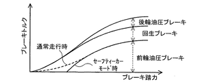
キャパシタ50の端子間電圧Vcapがセーフティーカーモード時下限電圧Vlowsc以上でブレーキ踏力Fbが値0でないときや(ステップS110,S120)、キャパシタ50の端子間電圧Vcapがセーフティーカーモード時下限電圧Vlowsc未満でブレーキ踏力Fbが値0でないとき(ステップS110,S130)、即ち、ドライバーによりブレーキペダル85が踏み込まれているときには、ブレーキ踏力Fbと前輪油圧ブレーキトルクと後輪油圧ブレーキトルクと回生ブレーキトルクとの関係を予め定めてROM74に記憶させておいたブレーキトルク設定用マップから入力したブレーキ踏力Fbに対応する回生ブレーキトルクを導出して仮回生トルクTmftmpとして設定する(ステップS200)。ブレーキトルク設定用マップの一例を図3に示す。図3中、前輪油圧ブレーキと回生ブレーキとの境界について、セーフティーカーモード時の境界を実線で示し、参考のために通常走行時の境界を破線で示した。図3の例では、ブレーキ踏力Fbがある程度小さい領域において、セーフティーカーモード時に、通常走行時に比して前輪油圧ブレーキトルクが小さくなると共に回生ブレーキトルクが大きくなるものとした。セーフティーカーモード時には、ブレーキペダル85が大きく踏み込まれる機会は少ないと考えられる。したがって、図3を用いることにより、ブレーキペダル85が軽く踏み込まれたときに、通常走行時に比して前輪用モータ24,26から出力される回生ブレーキトルクを大きくすることができ、通常走行時に比して大きな電力によってキャパシタ50を充電することができる。
When the inter-terminal voltage Vcap of the
こうしてモータ24,26の仮回生トルクTmftmpを設定すると、キャパシタ50の入力制限Winを前輪用モータ24,26の回転数Nfr,Nflの和で除して前輪用モータ24,26のトルク制限Tmfminを計算し(ステップS210)、設定した仮回生トルクTmftmpとトルク制限Tmfminのうち大きい方(絶対値としては小さい方)を前輪用モータ24,26のトルク指令Tmf*として設定すると共に設定した前輪用モータ24,26のトルク指令Tmf*をモータECU40に送信する(ステップS220)。トルク指令Tmf*を受信したモータECU40は、前輪用モータ24,26からトルク指令Tmf*に相当する回生トルクが出力されるようインバータ42,44のスイッチング素子をスイッチング制御する。この場合、前輪用モータ24,26により回生された電力がキャパシタ50に充電される。この場合も、セーフティーカーモードスイッチ87がオフされてからドライバーによりアクセルペダル83が大きく踏み込まれたときにモータ36にその性能を十分に発揮させる電力を供給することができる。
When the temporary regenerative torque Tmftmp of the
前輪用モータ24,26のトルク指令Tmf*を設定すると、ブレーキトルク設定用マップから入力したブレーキ踏力Fbに対応する前輪油圧ブレーキトルクを導出して仮前輪油圧ブレーキトルクTbftmpとして設定し(ステップS230)、仮回生トルクTmftmpからトルク指令Tmf*を減じて2倍した値を設定した仮前輪油圧ブレーキトルクTbftmpに加えて前輪油圧ブレーキトルクTbfとして設定すると共に設定した前輪油圧ブレーキTbfをブレーキECU62に送信する(ステップS240)。また、ブレーキトルク設定用マップから入力したブレーキ踏力Fbに対応する後輪油圧ブレーキトルクを導出して後輪油圧ブレーキトルクTbrとして設定すると共に設定した後輪油圧ブレーキTbrをブレーキECU62に送信して(ステップS250)、制動時制御ルーチンを終了する。前輪油圧ブレーキトルクTbfと後輪油圧ブレーキトルクTbrとを受信したブレーキECU62は、前輪29a,29bに前輪油圧ブレーキトルクTbfが作用すると共に後輪39a,39bに後輪油圧ブレーキトルクTbrが作用するようブレーキアクチュエータ64を駆動制御する。これにより、前輪29a,29bに前輪油圧ブレーキトルクTbfが作用すると共に後輪39a,39bに後輪油圧ブレーキトルクTbrが作用する。なお、前輪油圧ブレーキトルクTfをブレーキトルク設定用マップから導出した仮前輪油圧ブレーキトルクTbftmpに仮回生トルクTmftmpからトルク指令Tm*を減じて2倍した値を加えることによって計算することにより、トルク制限Tmfminにより前輪用モータ24,26から出力すべき回生トルクが制限されているときでも、車両に作用させる制動力が減少しないようにしている。
When the torque command Tmf * for the
以上説明した実施例のハイブリッド自動車20によれば、セーフティーカーモードスイッチ87がオンされているとき、キャパシタ50の端子間電圧Vcapが通常走行時の下限電圧Vlowよりも高いセーフティーカーモード時下限電圧Vlowsc未満のときにブレーキペダル85が踏み込まれていないときにはエンジン32からの動力の一部を用いて目標充電パワーPcap*に基づく電力でキャパシタ50の充電が行なわれるようモータ36のトルク指令Tmr*を設定してモータ36を制御し、バッテリ50の端子間電圧Vcapがセーフティーカーモード時下限電圧Vlowsc未満のときにブレーキペダル85が踏み込まれているときにはブレーキ踏力Fbに基づいてキャパシタ50の充電が行なわれるよう前輪用モータ24,26のトルク指令Tmf*を設定して前輪用モータ24,26を制御することにより、キャパシタ50の端子間電圧Vcapを通常走行時に比して比較的高い電圧にしておくことができる。これにより、その後にドライバーによりセーフティーカーモードスイッチ87がオフされてアクセルペダル83が大きく踏み込まれたときにモータ36にその性能を十分に発揮させる電力を供給することができ、ドライバーの加速要求に対処することができる。しかも、実施例のハイブリッド自動車20では、セーフティーカーモードスイッチ87がオンされているときにブレーキペダル85が踏み込まれているときには、セーフティーカーモードスイッチ87がオンされていないときに比して回生ブレーキトルクを大きく設定するから、セーフティーカーモードスイッチ87がオンされていないときに比してキャパシタ50への充電電力を大きくすることができる。もとより、ブレーキペダル85が踏み込まれていないときにはアクセル開度Accに基づいてエンジン32を制御し、ブレーキペダル85が踏み込まれているときにはブレーキ踏力Fbに基づいて前輪用モータ24,26やECB60を制御するから、ドライバーのアクセル操作やブレーキ操作に応じて走行することができる。
According to the
実施例のハイブリッド自動車20では、ブレーキ踏力Fbが値0のときには、アクセル開度Accに基づいてエンジン32を制御するものとしたが、ブレーキ踏力Fbが値0のときにアクセル開度Accも値0のとき、即ち、アクセルペダル83もブレーキペダル85も踏み込まれていないときには、モータ36から発電トルクを出力することにより、若干の制動力(エンジンからの動力だけを用いて走行する車両におけるエンジンブレーキに相当するもの)を車両に作用させるものとしてもよい。この場合、モータ36により発電された電力がキャパシタ50に充電される。
In the
実施例のハイブリッド自動車20では、セーフティーカーモードスイッチ87がオンされているときにブレーキペダル85が踏み込まれているときには、図3に例示したように、ブレーキ踏力Fbがある程度小さい領域において通常走行時に比して前輪油圧ブレーキトルクが小さくなると共に回生ブレーキトルクが大きくなる傾向のマップを用いるものとしたが、通常走行時と同様のマップを用いるものとしてもよい。
In the
実施例のハイブリッド自動車20では、ブレーキペダル85が踏み込まれているときには、前輪用モータ24,26を回生制御してキャパシタ50を充電するものとしたが、前輪用モータ24,26に加えてまたは代えて、モータ36を回生制御してキャパシタ50を充電するものとしてもよい。
In the
実施例のハイブリッド自動車20では、前輪用モータ24,26やモータ36と電力のやり取りが可能な蓄電装置としてキャパシタ50のみを備えるものとしたが、キャパシタ50以外に二次電池を搭載するものとしても構わない。
In the
実施例では、レース用のハイブリッド自動車20に本発明を適用した場合について説明したが、一般の公道を走行するハイブリッド自動車に本発明を適用してもよい。一般の公道を走行するハイブリッド自動車に本発明を適用した場合、例えば、セーフティーカーモードスイッチ87に相当するスイッチを備えているものではそのスイッチがオンされたときに、道路情報や車両の現在位置などを表示出力するナビゲーションシステムを備えるものでは追い越し禁止区間を走行しているときなどに、図2のセーフティーカーモード時制御ルーチンを実行するものとしてもよい。
In the embodiment, the case where the present invention is applied to the
実施例では、前輪に取り付けられたインホイールモータとしての前輪用モータ24,26と、エンジン32のクランクシャフト33に取り付けられたモータ36と、前輪用モータ24,26やモータ36と電力のやり取りが可能なキャパシタ50とを備えるハイブリッド自動車20に本発明を適用した場合について説明したが、走行用の動力を出力可能な内燃機関と、走行用の動力を入出力可能な電動機と、電動機と電力のやり取りが可能なキャパシタと、を備える車両であれば、如何なる車両に適用するものとしてもよい。
In the embodiment, the
ここで、実施例や変形例の主要な要素と課題を解決するための手段の欄に記載した発明の主要な要素との対応関係について説明する。実施例では、エンジン32が「内燃機関」に相当し、前輪用モータ24,26やモータ36が「電動機」に相当し、キャパシタ50が「キャパシタ」に相当し、電圧センサ54が「キャパシタ電圧検出手段」に相当し、セーフティーカーモードスイッチ87がオンされているとき、キャパシタ50の端子間電圧Vcapが通常走行時の下限電圧Vlowよりも高いセーフティーカーモード時下限電圧Vlowsc未満のときにブレーキペダル85が踏み込まれていないときにはエンジン32からの動力の一部を用いて目標充電パワーPcap*に基づく電力でキャパシタ50の充電が行なわれるようモータ36のトルク指令Tmr*を設定してモータECU40に送信すると共にアクセル開度Accに基づいてエンジン32を制御し、キャパシタ50の端子間電圧Vcapがセーフティーカーモード時下限電圧Vlowsc未満のときにブレーキペダル85が踏み込まれているときにはブレーキ踏力Fbに基づいてキャパシタ50の充電が行なわれるよう前輪用モータ24,26のトルク指令Tmf*を設定してモータECU40に送信する図2のセーフティーカーモード時制御ルーチンを実行するハイブリッド用電子制御ユニット70と受信したトルク指令Tmr*に基づいてモータ36を制御すると共にトルク指令Tmf*に基づいて前輪用モータ24,26を制御するモータECU40とが「制御手段」に相当する。また、モータ36が「第1の電動機」に相当し、前輪用モータ24,26が「第2の電動機」に相当する。
Here, the correspondence between the main elements of the embodiments and the modified examples and the main elements of the invention described in the column of means for solving the problems will be described. In the embodiment, the
ここで、本発明の車両において、「内燃機関」としては、ガソリンまたは軽油等の炭化水素系の燃料により動力を出力するものに限定されるものではなく、走行用の動力を出力可能なものであれば如何なるタイプの内燃機関としても構わない。「電動機」としては、インホイールモータとして構成された前輪用モータ24,26や同期発電電動機として構成されたモータ36などに限定されるものではなく、走行用の動力を入出力可能なものであれば如何なるタイプの電動機としても構わない。「キャパシタ」としては、電気二重層キャパシタとして構成されたキャパシタ50に限定されるものではなく、電動機と電力のやりとりが可能なものであれば如何なるタイプのキャパシタとしても構わない。「キャパシタ電圧検出手段」としては、電圧センサ54に限定されるものではなく、キャパシタ50の端子間電圧Vcapを検出するものであれば如何なるものとしても構わない。「制御手段」としては、メイン電子制御ユニット70とモータECU40とを組み合わせたものに限定されるものではなく、単一の電子制御ユニットとしても構わない。また、「制御手段」としては、セーフティーカーモードスイッチ87がオンされているとき、キャパシタ50の端子間電圧Vcapが通常走行時の下限電圧Vlowよりも高いセーフティーカーモード時下限電圧Vlowsc未満のときにブレーキペダル85が踏み込まれていないときにはエンジン32からの動力の一部を用いて目標充電パワーPcap*に基づく電力でキャパシタ50の充電が行なわれるようモータ36のトルク指令Tmr*を設定してモータ36を制御し、バッテリ50の端子間電圧Vcapがセーフティーカーモード時下限電圧Vlowsc未満のときにブレーキペダル85が踏み込まれているときにはブレーキ踏力Fbに基づいてキャパシタ50の充電が行なわれるよう前輪用モータ24,26のトルク指令Tmf*を設定して前輪用モータ24,26を制御するものに限定されるものではなく、前方の車両の追い越しを禁止する追い越し禁止モードが設定されている追い越し禁止モード時には、キャパシタ電圧が追い越し禁止モードが設定されていない通常走行時のキャパシタの使用下限電圧として予め定められた第1下限電圧よりも高い第2下限電圧以上となると共に運転者の操作に基づいて走行するよう内燃機関と電動機とを制御するものであれば如何なるものとしても構わない。なお、実施例や変形例の主要な要素と課題を解決するための手段の欄に記載した発明の主要な要素との対応関係は、実施例が課題を解決するための手段の欄に記載した発明を実施するための最良の形態を具体的に説明するための一例であることから、課題を解決するための手段の欄に記載した発明の要素を限定するものではない。即ち、課題を解決するための手段の欄に記載した発明についての解釈はその欄の記載に基づいて行なわれるべきものであり、実施例は課題を解決するための手段の欄に記載した発明の具体的な一例に過ぎないものである。
Here, in the vehicle of the present invention, the “internal combustion engine” is not limited to the one that outputs power by hydrocarbon fuel such as gasoline or light oil, but can output power for traveling. Any type of internal combustion engine may be used. The “motor” is not limited to the
以上、本発明を実施するための最良の形態について実施例を用いて説明したが、本発明はこうした実施例に何等限定されるものではなく、本発明の要旨を逸脱しない範囲内において、種々なる形態で実施し得ることは勿論である。 The best mode for carrying out the present invention has been described with reference to the embodiments. However, the present invention is not limited to these embodiments, and various modifications can be made without departing from the gist of the present invention. Of course, it can be implemented in the form.
本発明は、車両の製造産業などに利用可能である。 The present invention can be used in the vehicle manufacturing industry.
20 ハイブリッド自動車、21 前輪系、24,26 前輪用モータ、25,27 回転位置検出センサ、29a,29b 前輪、31 後輪系、32 エンジン、33 クランクシャフト、34 トランスミッション、36 モータ、37 回転位置検出センサ、38 デファレンシャルギヤ、39a,39b 後輪、40 モータ用電子制御ユニット(モータECU)、42,44,46 インバータ、50 キャパシタ、52 キャパシタ用電子制御ユニット(キャパシタECU)、54 電圧センサ、56 電流センサ、58 温度センサ、60 電子制御式油圧ブレーキユニット(ECB)、61 マスタシリンダ、61a マスタシリンダ圧センサ、62 ブレーキ用電子制御ユニット(ブレーキECU)、64 ブレーキアクチュエータ、66a,66b,68a,68b ホイールシリンダ、70 メイン電子制御ユニット、72 CPU、74 ROM、76 RAM、81 アップスイッチ、82 ダウンスイッチ、83 アクセルペダル、84 アクセルペダルポジションセンサ、85 ブレーキペダル、86 ブレーキペダルポジションセンサ、87 セーフティーカーモードスイッチ、88 ピットモードスイッチ88。
20 hybrid vehicle, 21 front wheel system, 24, 26 front wheel motor, 25, 27 rotational position detection sensor, 29a, 29b front wheel, 31 rear wheel system, 32 engine, 33 crankshaft, 34 transmission, 36 motor, 37 rotational position detection Sensor, 38 Differential gear, 39a, 39b Rear wheel, 40 Motor electronic control unit (motor ECU), 42, 44, 46 Inverter, 50 capacitor, 52 Capacitor electronic control unit (capacitor ECU), 54 Voltage sensor, 56 Current Sensor, 58 Temperature sensor, 60 Electronically controlled hydraulic brake unit (ECB), 61 Master cylinder, 61a Master cylinder pressure sensor, 62 Brake electronic control unit (brake ECU), 64 Brake actuator, 6 a, 66b, 68a, 68b Wheel cylinder, 70 main electronic control unit, 72 CPU, 74 ROM, 76 RAM, 81 up switch, 82 down switch, 83 accelerator pedal, 84 accelerator pedal position sensor, 85 brake pedal, 86 brake pedal Position sensor, 87 Safety car mode switch, 88
Claims (10)
前記キャパシタの端子間電圧であるキャパシタ電圧を検出するキャパシタ電圧検出手段と、
前方の車両の追い越しを禁止する追い越し禁止モードが設定されている追い越し禁止モード時には、前記検出されるキャパシタ電圧が前記追い越し禁止モードが設定されていない通常走行時の前記キャパシタの使用下限電圧として予め定められた第1下限電圧よりも高い第2下限電圧以上となると共に運転者の操作に基づいて走行するよう前記内燃機関と前記電動機とを制御する制御手段と、
を備える車両。 A vehicle comprising an internal combustion engine capable of outputting power for traveling, an electric motor capable of inputting / outputting power for traveling, and a capacitor capable of exchanging electric power with the electric motor,
Capacitor voltage detecting means for detecting a capacitor voltage which is a voltage between terminals of the capacitor;
In the overtaking prohibition mode in which the overtaking prohibition mode for prohibiting overtaking of the vehicle ahead is set, the detected capacitor voltage is determined in advance as the lower limit voltage for use of the capacitor during normal driving in which the overtaking prohibition mode is not set. Control means for controlling the internal combustion engine and the electric motor to travel on the basis of a driver's operation while being equal to or higher than a second lower limit voltage higher than the first lower limit voltage.
A vehicle comprising:
前記電動機は、前記内燃機関の出力軸に取り付けられてなり、
前記制御手段は、ブレーキ操作が行なわれていないときに前記キャパシタの充電を行なうときには、前記内燃機関から出力される動力の一部を用いて前記電動機により発電が行なわれるよう該電動機を制御する手段である、
車両。 A vehicle according to any one of claims 1 to 4,
The electric motor is attached to the output shaft of the internal combustion engine,
The control means controls the electric motor so that the electric motor generates power using a part of the power output from the internal combustion engine when charging the capacitor when the brake operation is not performed. Is,
vehicle.
前記電動機は、前記内燃機関の出力軸に取り付けられた第1の電動機と前記内燃機関の出力軸が接続された車軸である第1の車軸とは異なる第2の車軸に取り付けられた第2の電動機とを有し、
前記制御手段は、ブレーキ操作が行なわれていないときに前記キャパシタの充電を行なうときには前記内燃機関から出力される動力の一部を用いて前記第1の電動機により発電が行なわれるよう該第1の電動機を制御し、ブレーキ操作が行なわれているときに前記キャパシタの充電を行なうときには前記第2の電動機から前記車両に制動力が作用するよう該第2の電動機を制御する手段である、
車両。 A vehicle according to any one of claims 1 to 4,
The electric motor includes a first electric motor attached to an output shaft of the internal combustion engine and a second axle attached to a second axle different from the first axle which is an axle to which the output shaft of the internal combustion engine is connected. An electric motor,
The control means uses the first electric motor to generate electricity using a part of the power output from the internal combustion engine when charging the capacitor when the brake operation is not performed. Means for controlling the second electric motor so that a braking force acts on the vehicle from the second electric motor when the electric motor is controlled and the capacitor is charged when a brake operation is performed;
vehicle.
前方の車両の追い越しを禁止する追い越し禁止モードが設定されている追い越し禁止モード時には、前記キャパシタの端子間電圧であるキャパシタ電圧が前記追い越し禁止モードが設定されていない通常走行時の前記キャパシタの使用下限電圧として予め定められた第1下限電圧よりも高い第2下限電圧以上となると共に運転者の操作に基づいて走行するよう前記内燃機関と前記電動機とを制御する、
ことを特徴とする車両の制御方法。 A vehicle control method comprising: an internal combustion engine capable of outputting power for traveling; an electric motor capable of inputting / outputting power for traveling; and a capacitor capable of exchanging electric power with the electric motor,
In the overtaking prohibition mode in which the overtaking prohibition mode for prohibiting overtaking of the preceding vehicle is set, the capacitor voltage, which is the voltage between the terminals of the capacitor, is the lower limit of use of the capacitor during normal driving in which the overtaking prohibition mode is not set Controlling the internal combustion engine and the electric motor so as to travel based on a driver's operation while being equal to or higher than a second lower limit voltage higher than a first lower limit voltage predetermined as a voltage;
A method for controlling a vehicle.
Priority Applications (1)
| Application Number | Priority Date | Filing Date | Title |
|---|---|---|---|
| JP2007183167A JP2009018708A (en) | 2007-07-12 | 2007-07-12 | Vehicle and control method therefor |
Applications Claiming Priority (1)
| Application Number | Priority Date | Filing Date | Title |
|---|---|---|---|
| JP2007183167A JP2009018708A (en) | 2007-07-12 | 2007-07-12 | Vehicle and control method therefor |
Publications (1)
| Publication Number | Publication Date |
|---|---|
| JP2009018708A true JP2009018708A (en) | 2009-01-29 |
Family
ID=40358723
Family Applications (1)
| Application Number | Title | Priority Date | Filing Date |
|---|---|---|---|
| JP2007183167A Pending JP2009018708A (en) | 2007-07-12 | 2007-07-12 | Vehicle and control method therefor |
Country Status (1)
| Country | Link |
|---|---|
| JP (1) | JP2009018708A (en) |
Cited By (3)
| Publication number | Priority date | Publication date | Assignee | Title |
|---|---|---|---|---|
| JP2010200590A (en) * | 2009-02-27 | 2010-09-09 | Mitsubishi Motors Corp | Device for regenerative braking control of electric vehicle |
| JP2020055417A (en) * | 2018-10-02 | 2020-04-09 | マツダ株式会社 | Vehicle drive device |
| CN111867870A (en) * | 2018-03-20 | 2020-10-30 | 马自达汽车株式会社 | Vehicle drive device |
-
2007
- 2007-07-12 JP JP2007183167A patent/JP2009018708A/en active Pending
Cited By (5)
| Publication number | Priority date | Publication date | Assignee | Title |
|---|---|---|---|---|
| JP2010200590A (en) * | 2009-02-27 | 2010-09-09 | Mitsubishi Motors Corp | Device for regenerative braking control of electric vehicle |
| CN111867870A (en) * | 2018-03-20 | 2020-10-30 | 马自达汽车株式会社 | Vehicle drive device |
| CN111867870B (en) * | 2018-03-20 | 2023-09-29 | 马自达汽车株式会社 | Vehicle driving device |
| JP2020055417A (en) * | 2018-10-02 | 2020-04-09 | マツダ株式会社 | Vehicle drive device |
| JP7049584B2 (en) | 2018-10-02 | 2022-04-07 | マツダ株式会社 | Vehicle drive |
Similar Documents
| Publication | Publication Date | Title |
|---|---|---|
| US8068946B2 (en) | Hybrid vehicle and control method thereof | |
| JP5944199B2 (en) | Vehicle and vehicle control method | |
| US8244420B2 (en) | Vehicle, vehicle control method, and drive unit | |
| US9827874B2 (en) | Vehicle | |
| US20160304096A1 (en) | Brake control for stop/start vehicle | |
| JP6428672B2 (en) | Control device for vehicle drive device | |
| US10099694B2 (en) | Motor vehicle | |
| US9701300B2 (en) | Hybrid vehicle | |
| CN107150678B (en) | Vehicle comprising a travel motor | |
| JP2006266193A (en) | Vehicle and its controlling method | |
| CN104245387A (en) | Vehicle, and vehicle control method | |
| JP2013141858A (en) | Controller for hybrid vehicle | |
| JP2020100360A (en) | Torque control device of four wheel drive vehicle | |
| JP2013187959A (en) | Vehicle | |
| JP2011097666A (en) | Vehicle and control method therefor | |
| JP2019126128A (en) | Automobile | |
| JP2009214580A (en) | Hybrid vehicle and control method therefor | |
| JP2009017725A (en) | Vehicle and control method therefor | |
| JP2009018708A (en) | Vehicle and control method therefor | |
| JP3622656B2 (en) | Vehicle braking force control device | |
| JP2015000675A (en) | Control method for hybrid vehicle during cost drive and hybrid | |
| JP2009018709A (en) | Vehicle and control method therefor | |
| JP2009018699A (en) | Hybrid vehicle and control method therefor | |
| JP2016093034A (en) | Automobile | |
| JP5135924B2 (en) | Hybrid car |