JP2009013620A - Partition panel and its manufacturing method - Google Patents
Partition panel and its manufacturing method Download PDFInfo
- Publication number
- JP2009013620A JP2009013620A JP2007174734A JP2007174734A JP2009013620A JP 2009013620 A JP2009013620 A JP 2009013620A JP 2007174734 A JP2007174734 A JP 2007174734A JP 2007174734 A JP2007174734 A JP 2007174734A JP 2009013620 A JP2009013620 A JP 2009013620A
- Authority
- JP
- Japan
- Prior art keywords
- frame
- hole
- locking
- hook
- screw
- Prior art date
- Legal status (The legal status is an assumption and is not a legal conclusion. Google has not performed a legal analysis and makes no representation as to the accuracy of the status listed.)
- Pending
Links
Images


Abstract
Description
本発明は、オフィス等の室内を仕切る間仕切パネル、およびその製造方法に関する。 The present invention relates to a partition panel for partitioning a room such as an office and a manufacturing method thereof.
従来、据付式の間仕切パネルにおいては、フレームを現地で組み立て、その後、フレームの両側面に、化粧パネルを装着して、完成させることが多い。 Conventionally, a stationary partition panel is often completed by assembling a frame on-site and then mounting decorative panels on both sides of the frame.
また、天井に設けたレールに沿って移動するランナに、間仕切パネルを吊支し、間仕切パネルを、レールに沿って移動しうるようにした移動間仕切装置における間仕切パネルは、フレームをランナに吊支した状態で、フレームに化粧パネルを装着することが困難であり、しかも間仕切パネルの縁部に、天井や床との隙間を閉塞する閉塞手段や、アルミニュウム合金製の縁材を装着する等の作業が煩雑であるため、予め工場において組み立てておくことが多い(例えば特許文献1参照)。
しかし、近年、移動間仕切の間仕切パネルと据付式の間仕切パネルとのデザインの統一を図るとともに、移動間仕切の間仕切パネルを工場や現地において、一人でも簡単かつ迅速に組み立てることが要望されるようになってきており、従来の移動間仕切の間仕切パネルの構造では、上述したように、組み付け作業が煩雑過ぎて、上記の要望を満たすことが実質的に難しい状況である。 However, in recent years, it has been demanded to unify the design of the partition panel for moving partitions and the stationary partition panel, and to easily and quickly assemble the partition panels for moving partitions in the factory or on site. In the structure of the conventional partition panel for moving partitions, as described above, the assembling work is too complicated and it is substantially difficult to satisfy the above demand.
本発明は、従来の技術が有する上記のような問題に鑑み、構造が簡単で、組み付け作業が容易な間仕切パネル、および、一人でも簡単に組立て作業ができる、簡単な間仕切パネルの製造方法を提供することを目的としている。 The present invention provides a partition panel that has a simple structure and is easy to assemble, and a method for manufacturing a simple partition panel that can be easily assembled by one person in view of the above-described problems of the prior art. The purpose is to do.
本発明によると、上記課題は次のようにして解決される。
(1)間仕切パネルにおいて、左右1対の縦杆の各端部同士を、横杆をもって互いに連結し、かつ各縦杆の外側端面に、ねじ挿通孔と長手方向を向く長孔とを設けてなる矩形枠状のフレームと、裏面両側部に複数の係止孔が設けられ、かつ前記フレームの両側面に配設された1対の化粧パネルと、前記フレームの両縦杆の内側面に沿って配設され、両側縁に、前記両化粧パネルの係止孔に係合するフックを有するとともに、前記フレームの縦杆に設けられた長孔を挿通する移動操作用のボルトが螺合しうるねじ孔と、前記フレームの縦杆に設けられたねじ挿通孔を挿通する固定ねじが螺合するねじ孔とが設けられた係止部材とを備え、前記係止部材の各フックを、対応する両化粧パネルの係合孔の縁に係合させるとともに、前記係止部材を、固定ねじをもって縦杆にねじ止めする。
According to the present invention, the above problem is solved as follows.
(1) In the partition panel, the ends of a pair of right and left vertical hooks are connected to each other with horizontal hooks, and a screw insertion hole and a long hole facing the longitudinal direction are provided on the outer end face of each vertical hook. A pair of decorative panels provided with a plurality of locking holes on both sides of the back surface and disposed on both side surfaces of the frame, and along the inner side surfaces of both vertical rods of the frame And a hook for engaging with the locking holes of the two decorative panels at both side edges, and a bolt for moving operation that passes through a long hole provided in the vertical shaft of the frame can be screwed together. A locking member provided with a screw hole and a screw hole into which a fixing screw that passes through a screw insertion hole provided in the vertical shaft of the frame is screwed, and each hook of the locking member corresponds to While engaging with the edges of the engagement holes of both decorative panels, the locking member is fixed. Screwed to the vertical rod with a screw.
(2)上記(1)項において、フレームの上下いずれかの端部に、フックに係合している係止孔の縁がフックから外れる方向への化粧パネルの移動を阻止する外向き突片を設ける。 (2) In the above item (1), the outward projecting piece that prevents the decorative panel from moving in the direction in which the edge of the locking hole engaged with the hook is detached from the hook at either the upper or lower end of the frame Is provided.
(3)間仕切パネルの製造方法において、裏面両側部に複数の係止孔が設けられた化粧パネルを、裏面を上方に向けて水平として支持体上に支持し、その上方に、側端面にねじ挿通孔と長手方向を向く長孔とが設けられた1対の縦杆の各端部同士を、横杆をもって互いに連結してなる矩形枠状のフレームを、水平として載置し、次いで、両側縁にフックを有するとともに、前記フレームの縦杆に設けられた長孔を挿通する移動操作用のボルトが螺合しうるねじ孔と、前記フレームの縦杆に設けられたねじ挿通孔を挿通する固定ねじが螺合しうるねじ孔とが設けられた係止部材を、一方の側縁のフックが、前記化粧パネルの係止孔に嵌合し、かつ外側面が前記フレームの両縦杆の内側面に沿うようにして、前記化粧パネルの裏面上に載置し、次いで、前記化粧パネルと同形の別の化粧パネルを、その裏面を下にして、かつ各係止孔が前記係止部材の他方の側縁のフックに嵌合するようにして、前記フレーム上に水平に載置し、その後またはそれ以前に、各係止部材のボルト螺合用のねじ孔に、前記縦杆の長孔を通した移動操作用のボルトの先端部を螺合し、前記ボルトを前記長孔に沿って、前記各フックの先端が向く方向に移動させることにより、前記各フックを対応する各係止孔の縁に係止させ、その後、前記縦杆のねじ挿通孔に挿通した固定ねじを、前記係止部材の固定ねじ用のねじ孔に螺合して、係止部材を縦杆に固着する。 (3) In the partition panel manufacturing method, a decorative panel provided with a plurality of locking holes on both sides of the back surface is supported on a support body with the back surface facing upward and is screwed on the side end surface A rectangular frame-like frame formed by connecting the ends of a pair of vertical gutters provided with an insertion hole and a long hole facing in the longitudinal direction to each other with a horizontal gutter is placed horizontally, and then both sides A hook is provided at the edge, and a screw hole through which a bolt for movement operation that passes through a long hole provided in the vertical shaft of the frame can be screwed, and a screw insertion hole provided in the vertical shaft of the frame are inserted. A locking member provided with a screw hole into which a fixing screw can be screwed, a hook on one side edge is fitted into a locking hole of the decorative panel, and an outer side surface of both vertical shafts of the frame Place it on the back of the decorative panel along the inner surface, and then , Another decorative panel having the same shape as the decorative panel is placed horizontally on the frame so that the back surface of the decorative panel is downward and each locking hole is engaged with the hook on the other side edge of the locking member. After that, or before or before that, the tip of the bolt for moving operation through the elongated hole of the vertical rod is screwed into the screw hole for screwing of each locking member, and the bolt is By moving the hooks in the direction in which the tips of the hooks are directed along the long holes, the hooks are locked to the edges of the corresponding locking holes, and then fixed through the screw insertion holes of the vertical hook. The screw is screwed into the screw hole for the fixing screw of the locking member, and the locking member is fixed to the vertical shaft.
(4)上記(3)項において、各フックの先端が向く方向にあるフレームの端部に、外向きの1対の突片を設け、この両突片を、両化粧パネルの端面に当接させて、各化粧パネルとフレームとの位置決めを図る。 (4) In the above item (3), a pair of outward projecting pieces are provided at the end of the frame in the direction in which the tip of each hook faces, and these projecting pieces are in contact with the end faces of both decorative panels. Then, each decorative panel and the frame are positioned.
本発明によると、次のような効果を奏することができる。
請求項1および3記載の発明によると、背中合わせとした1対の化粧パネルの間に、フレームと1対の係止部材を、各係止部材のフックが、対応する各化粧パネルの係止孔に嵌合するようにして、サンドイッチ状に挟んで、水平に支持した後、縦杆の長孔を通して、各係止部材のボルト螺合用のねじ孔に螺合した移動操作用のボルトを用いて、係止部材を、各フックの先端が向く方向に移動させることにより、各フックを対応する各係止孔の縁に係止させ、その状態で、縦杆のねじ挿通孔に挿通した固定ねじを、係止部材の固定ねじ用のねじ孔に螺合して、係止部材を縦杆に固着することにより、間仕切パネルを、現場等においても、一人でも簡単かつ迅速に組み立てることができる。
なお、間仕切パネルの完成後、係止部材のボルト螺合用のねじ孔に螺合したボルトは、外して、次の間仕切パネルの組立てに再利用することができる。
また、フレームと、1対の化粧パネルと、1対の係止部材とのわずかの部品点数だけで、間仕切パネルを簡単に形成することができ、構造を簡素化することができる。
According to the present invention, the following effects can be achieved.
According to the first and third aspects of the present invention, the frame and the pair of locking members are arranged between the pair of decorative panels that are back-to-back, and the hooks of the locking members correspond to the locking holes of the corresponding decorative panels. Using a bolt for moving operation that is sandwiched in a sandwich shape and supported horizontally, and then screwed into a screw hole for screwing a bolt of each locking member through a long hole in a vertical hook. The locking member is moved in the direction in which the tip of each hook faces, so that each hook is locked to the edge of each corresponding locking hole, and in that state, the fixing screw inserted through the vertical screw insertion hole Are screwed into the screw holes for fixing screws of the locking member, and the locking member is fixed to the vertical shaft, so that the partition panel can be easily and quickly assembled by one person even at the site or the like.
After completion of the partition panel, the bolts screwed into the screw holes for screwing the locking members can be removed and reused for assembling the next partition panel.
Further, the partition panel can be easily formed with only a small number of parts including the frame, the pair of decorative panels, and the pair of locking members, and the structure can be simplified.
請求項2および4記載の発明によると、フレームの上下いずれかの端部に、フックに係合している係止孔の縁がフックから外れる方向への化粧パネルの移動を阻止する外向き突片を設けてあるので、化粧パネルは、フレームに、外れることなく、確実に装着される。 According to the second and fourth aspects of the present invention, the outward projection which prevents the decorative panel from moving in the direction in which the edge of the locking hole engaged with the hook is released from the hook at either the upper or lower end of the frame. Since the piece is provided, the decorative panel is securely attached to the frame without being detached.
以下、本発明の一実施形態を、添付図面を参照して説明する。
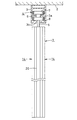
図1は、本発明の間仕切パネルの一実施形態を、天井に設けたレールに沿って移動するランナに吊支した状態を示す側面図、図2は、その拡大縦断正面図、図3は、図1のIII−III線に沿う拡大横断平面図である。
Hereinafter, an embodiment of the present invention will be described with reference to the accompanying drawings.
1 is a side view showing a state in which an embodiment of a partition panel of the present invention is suspended from a runner moving along a rail provided on a ceiling, FIG. 2 is an enlarged longitudinal front view thereof, and FIG. FIG. 3 is an enlarged transverse plan view taken along line III-III in FIG. 1.
本発明の間仕切パネル1は、天井2の下面に固着したレール3に沿って移動するランナ4、4に、1対の吊りボルト5、5をもって吊支されている。
ランナ4は、どのようなタイプのものでもよいが、この例では、吊りボルト5の上端部に、スペーサ6を介して、上下に離して枢支した1対の水平ローラ7、8を備えるものとしてある。
The
The
図2に示すように、上段のローラ7は、下端が開口する下向きコ字状としたレール3の内面における中位部の一側より内向き突設したローラ受片3a上に、また、下段のローラ8は、レール3の内面における下端部の他側より内向き突設したローラ受片3b上に、それぞれ受支されて、互いに逆方向に回転しつつ、レール3に沿って移動しうるようになっている。
As shown in FIG. 2, the
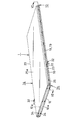
間仕切パネル1は、組立て要領を示す図4(水平に寝かした状態で示してある)に示すように、左右1対の縦杆9、10の各端部同士を、横杆11、12をもって互いに連結してなる矩形枠状のフレーム13と、フレーム13の両側面に配設された、構造および形状を互いに同一とした1対の化粧パネル14、14と、フレーム13の両縦杆9、10の内側面に沿って配設され、両側縁に、両化粧パネル14、14を係止する複数のフック15が設けられた係止部材16とを備えている。
As shown in FIG. 4 (shown in a state of being laid horizontally), the
縦杆9、10は、アルミニュウム合金の押出材により形成されている。
図3に示すように、縦杆9の外側面には、山形の凸条17が、また縦杆10の外側面には、上記凸条17が嵌合しうるようにした凹条18がそれぞれ設けられ、さらに、凸条17の頂部と、凹条18の底部とには、凹溝19、19が設けられている。
The
As shown in FIG. 3, a mountain-
各凹溝19の開口部には、ゴム等の弾性体からなる閉塞部材20が、着脱自在に装着されている。また、凹条18の内側面には、ゴム等の弾性体からなる1対のシール部材21、21が設けられている。
A
左右の縦杆9、10の外側面には、長手方向、すなわち使用状態での上下方向を向く複数の長孔22と、複数のねじ挿通孔23とが、上下方向に適宜の間隔をもって設けられている。
The outer surfaces of the left and right
上下の横杆11、12は、金属板を折曲して形成した角管またはチャンネル材からなり、それらの左右方向の端部には、吊りボルト5、5その他の部材を挿通させるための上下方向の通孔24、24が設けられている。
なお、間仕切パネル1には、その上端と天井2との間、およびその下端と床(図示略)との間の間隙を閉塞する閉塞部材、およびそれを移動させる手段、並びに、吊りボルト5、5の下端を連結する手段等が設けられているが、それらは、本発明とは直接関係しないので、図示および詳細な説明は省略してある。
The upper and
The
図4に示すように、上方の横杆11の上端と、下方の横杆12の下端には、各化粧パネル14の上端面および下端面に当接するようにした外向きの突片11a、11a、12a、12aが設けられている。
As shown in FIG. 4, outward projecting
化粧パネル14は、図3および図4に示すように、金属製の化粧板25における方形とした平板部25aの周縁部を、裏面側に内向きコ字状に折り曲げて、折返し縁部25bを形成し、この折返し縁部25bより内側における平板部25aの裏面に、石膏ボード26を固着したものよりなっている。
The
化粧パネル14における左右の折返し縁部25bの背面には、係止部材16の各側縁に設けられた複数のフック15が係合しうるようにした複数の縦長のスリット状の係止孔27が設けられている。
A plurality of vertically long slit-
左右の係止部材16、16は、互いに内向きに開口する平面視コ字状のチャンネル材28の外側面に、両側縁に同一方向を向く鉤形の複数のフック15が形成された金属板のフック基片29をスポット溶接したものよりなり、その長手方向には、フレーム13の縦杆9、10に設けられた長孔22に対応するねじ孔30と、同じくねじ挿通孔23に対応するねじ孔31とが設けられている。
The left and
次に、図4〜図6を参照して、この間仕切パネル1の製造時における部品の組立て要領について説明する。
図4に示すように、1枚の化粧パネル14を、裏面を上方に向けて水平として、床面または支持体(図示略)上に支持し、次いで、その上方より、フレーム13を、その突片11a、12aが化粧パネル14の使用状態での上端面および下端面に当接して、化粧パネル14を挟むようにして、水平に載置するとともに、そのフレーム13における左右の縦杆9、10の内側面に沿って、1対の係止部材16、16を、その一方の縁に設けられた複数のフック15が、化粧パネル14における対応する係止孔27に上方より嵌合するようにして、かつ他方の縁に設けられたフック15が、水平としたフレーム13より上方に突出するようにして、水平に載置し、さらにその上方より、別の化粧パネル14を、裏面を下方に向けて水平として、その係止孔27が対応する係止部材16の上方に突出する各フックに嵌合し、かつその化粧パネル14の使用状態での上端面および下端面が、フレーム13の突片11a、12aに挟まれるようにして載置する。
Next, with reference to FIGS. 4-6, the assembly procedure of the components at the time of manufacture of this
As shown in FIG. 4, one
なお、上方の化粧パネル14をフレーム13上に載置する前に、フレーム13内に、吊りボルト5、5、その下端を連結する手段、閉塞部材、およびそれを移動させる手段等を、必要に応じて予め装着しておく。
Before placing the upper
こうして、上下2枚の化粧パネル14、14間に、フレーム13と1対の係止部材16、16とが、サンドイッチ状に挟まれた状態で、係止部材16の移動操作用の左右1対のボルト32、32の先端部を、フレーム13における左右の側端面におけるいずれかの長孔22、22を通して、左右1対の係止部材16、16における左右に対向するいずれかのねじ孔30、30に螺合する。この状態を、図5に示してある。
なお、上方の化粧パネル14を、フレーム13上に載置する前に、各係止部材16におけるいずれかのねじ孔30に、長孔22を通したボルト32の先端部を螺合しておいてもよい。
Thus, in the state where the
Before the upper
次いで、左右のボルト32、32を、把持して、図5に矢印で示すように、長孔22、22に沿って、各フック15の先端が向く方向(図4においては左方)に移動させることにより、左右の係止部材16、16を、フレーム13および上下の化粧パネル14、14に対して、図6に矢印で示す方向に移動させ、各フック15を、対応する各係止孔27の縁に係止させる。
Next, the left and
各フック15が、対応する各係止孔27の縁に完全に係止したとき、各係止部材16のすべてのねじ孔31が、フレーム13のねじ挿通孔23と整合するように、ねじ孔31とねじ挿通孔23との位置を予め定めておき、それらが互いに整合した状態で、固定ねじ33を、ねじ挿通孔23を通して、ねじ孔31に螺合して締付け、各係止部材16をフレーム13に固着する。
When the
また、フレーム13における各突片11a、12aを、化粧パネル14の上下の端面に、固定ねじ34をもって固着する。なお、この固定ねじ34のねじ止め作業は、下方の化粧パネル14上にフレーム13を載置したとき、および、フレーム13上に、さらに別の化粧パネル14を載置したときに、その都度行ってもよい。
Further, the projecting
こうして、固定ねじ33、34をもってねじ止めすることにより、フレーム13に対して、両係止部材16、16と、両化粧パネル14、14とが強固に固着され、間仕切パネル1が完成する。
間仕切パネル1の完成後、各係止部材16のねじ孔30に螺合したボルト32は、外して、次の間仕切パネルの組立てに再利用することができる。
Thus, by fastening with the fixing screws 33 and 34, both the locking
After the
また、間仕切パネル1の完成後、1対の吊りボルト5、5の端部に設けたランナ4、4を、レール3に装架することにより、間仕切パネル1を、レール3より吊支して、移動させることができる。
In addition, after the
以上から明らかなように、本発明の間仕切パネル、およびその製造方法によると、間仕切パネル1を、現場等においても、一人でも簡単かつ迅速に組み立てることができ、また、間仕切パネルの部品点数は少ないため、構造を簡素化することができる。
As apparent from the above, according to the partition panel of the present invention and the manufacturing method thereof, the
さらに、フレーム13の上下いずれかの端部に、フック15に係合している係止孔27の縁がフック15から外れる方向への化粧パネル14の移動を阻止する外向き突片12aを設けてあるので、化粧パネル14は、フレーム15に、外れることなく、確実に装着される。
Further, an outward projecting
本発明は、上記の実施形態のみに制限されるものではなく、特許請求の範囲を逸脱しない範囲で、変形した態様での実施が可能である。
例えば、上記実施形態においては、各縦杆9、10に、長孔22およびねじ挿通孔を、それぞれ複数個ずつ設け、かつ各係止部材16にも、ねじ孔30、31をそれぞれ複数個ずつ設けてあるが、これらは、すべて最低1個ずつ設ければよい。
The present invention is not limited to the above-described embodiment, and can be implemented in a modified form without departing from the scope of the claims.
For example, in the above embodiment, each of the
また、上記実施形態においては、間仕切パネル1を、吊りボルト5、5により吊支したとき、各係止部材16の各フック15が、すべて下方を向くようにしてあるが、これらのフック15を、すべて上方を向くようにし、そのフック15に、各化粧パネル14の係止孔27の上縁が係止されるようにすることにより、各化粧パネル14を、このフック15のみによって、フレーム15に係止し、フレーム15における上下の突片11a、12aを省略して実施することもできる。
In the above embodiment, when the
さらに、係止孔27を、係止部材16の両側面に設け、これに、化粧パネル14の背面に突設したフック15を嵌合した後、係止部材16を、フック15が係止孔27の縁に深く噛み合う方向に移動させるようにしてもよい。
Further, the locking holes 27 are provided on both side surfaces of the locking
上記実施形態は、本発明を、移動間仕切装置における間仕切パネル、およびその製造方法に適用したものであるが、本発明は、据付式の間仕切パネル、およびその製造方法にも適用しうることはいうまでもない。 Although the said embodiment applies this invention to the partition panel in a moving partition apparatus, and its manufacturing method, it says that this invention can be applied also to a stationary partition panel and its manufacturing method. Not too long.
1 間仕切パネル
2 天井
3 レール
3a、3b ローラ受片
4 ランナ
5 吊りボルト
6 スペーサ
7、8 水平ローラ
9、10 縦杆
11、12 横杆
11a、12a 突片
13 フレーム
14 化粧パネル
15 フック
16 係止部材
17 凸条
18 凹条
19 凹溝
20 閉塞部材
21 シール部材
22 長孔
23 ねじ挿通孔
24 通孔
25 化粧板
25a平板部
25b折返し縁部
26 石膏ボード
27 係止孔
28 チャンネル材
29 フック基片
30、31 ねじ孔
32 ボルト
33、34 固定ねじ
DESCRIPTION OF
Claims (4)
裏面両側部に複数の係止孔が設けられ、かつ前記フレームの両側面に配設された1対の化粧パネルと、
前記フレームの両縦杆の内側面に沿って配設され、両側縁に、前記両化粧パネルの係止孔に係合するフックを有するとともに、前記フレームの縦杆に設けられた長孔を挿通する移動操作用のボルトが螺合しうるねじ孔と、前記フレームの縦杆に設けられたねじ挿通孔を挿通する固定ねじが螺合するねじ孔とが設けられた係止部材とを備え、
前記係止部材の各フックを、対応する両化粧パネルの係合孔の縁に係合させるとともに、前記係止部材を、固定ねじをもって縦杆にねじ止めしたことを特徴とする間仕切パネル。 A rectangular frame-like frame in which the ends of a pair of left and right vertical rods are connected to each other with horizontal ribs, and a screw insertion hole and a long hole facing the longitudinal direction are provided on the outer end surface of each vertical rod; ,
A pair of decorative panels provided with a plurality of locking holes on both sides of the back surface and disposed on both sides of the frame;
The hooks are disposed along the inner side surfaces of the vertical hoists of the frame, and have hooks that engage with the engaging holes of the decorative panels on both side edges, and through the long holes provided in the vertical hoists of the frame. And a locking member provided with a screw hole into which a bolt for moving operation can be screwed, and a screw hole into which a fixing screw that passes through a screw insertion hole provided in the vertical shaft of the frame is screwed.
A partition panel characterized in that each hook of the locking member is engaged with an edge of a corresponding engagement hole of both decorative panels, and the locking member is screwed to a vertical hook with a fixing screw.
Priority Applications (2)
| Application Number | Priority Date | Filing Date | Title |
|---|---|---|---|
| JP2007174734A JP2009013620A (en) | 2007-07-03 | 2007-07-03 | Partition panel and its manufacturing method |
| US12/166,846 US8033071B2 (en) | 2007-07-03 | 2008-07-02 | Partition panel and a method of assembling it |
Applications Claiming Priority (1)
| Application Number | Priority Date | Filing Date | Title |
|---|---|---|---|
| JP2007174734A JP2009013620A (en) | 2007-07-03 | 2007-07-03 | Partition panel and its manufacturing method |
Publications (1)
| Publication Number | Publication Date |
|---|---|
| JP2009013620A true JP2009013620A (en) | 2009-01-22 |
Family
ID=40354849
Family Applications (1)
| Application Number | Title | Priority Date | Filing Date |
|---|---|---|---|
| JP2007174734A Pending JP2009013620A (en) | 2007-07-03 | 2007-07-03 | Partition panel and its manufacturing method |
Country Status (1)
| Country | Link |
|---|---|
| JP (1) | JP2009013620A (en) |
Cited By (2)
| Publication number | Priority date | Publication date | Assignee | Title |
|---|---|---|---|---|
| JP2016148169A (en) * | 2015-02-10 | 2016-08-18 | 株式会社岡村製作所 | Method for assembling partition panel |
| CN115288358A (en) * | 2022-07-26 | 2022-11-04 | 昆明华城兴建材有限公司 | Fiber reinforced cement board built-in fixed net rack |
Citations (5)
| Publication number | Priority date | Publication date | Assignee | Title |
|---|---|---|---|---|
| JPH0379314U (en) * | 1989-12-02 | 1991-08-13 | ||
| JPH04353142A (en) * | 1991-05-31 | 1992-12-08 | Kokuyo Co Ltd | Installing structure for panel |
| JPH09302821A (en) * | 1996-05-14 | 1997-11-25 | Okamura Corp | Partition panel |
| JP2004169510A (en) * | 2002-11-22 | 2004-06-17 | Sumitomo Metal Ind Ltd | Anchor post for steel-framed column and assembling method therefor |
| JP2006249676A (en) * | 2005-03-08 | 2006-09-21 | Ykk Ap株式会社 | Panel body |
-
2007
- 2007-07-03 JP JP2007174734A patent/JP2009013620A/en active Pending
Patent Citations (5)
| Publication number | Priority date | Publication date | Assignee | Title |
|---|---|---|---|---|
| JPH0379314U (en) * | 1989-12-02 | 1991-08-13 | ||
| JPH04353142A (en) * | 1991-05-31 | 1992-12-08 | Kokuyo Co Ltd | Installing structure for panel |
| JPH09302821A (en) * | 1996-05-14 | 1997-11-25 | Okamura Corp | Partition panel |
| JP2004169510A (en) * | 2002-11-22 | 2004-06-17 | Sumitomo Metal Ind Ltd | Anchor post for steel-framed column and assembling method therefor |
| JP2006249676A (en) * | 2005-03-08 | 2006-09-21 | Ykk Ap株式会社 | Panel body |
Cited By (2)
| Publication number | Priority date | Publication date | Assignee | Title |
|---|---|---|---|---|
| JP2016148169A (en) * | 2015-02-10 | 2016-08-18 | 株式会社岡村製作所 | Method for assembling partition panel |
| CN115288358A (en) * | 2022-07-26 | 2022-11-04 | 昆明华城兴建材有限公司 | Fiber reinforced cement board built-in fixed net rack |
Similar Documents
| Publication | Publication Date | Title |
|---|---|---|
| KR102251075B1 (en) | System furniture having vertical level control structure of vertical plate | |
| JP2009013620A (en) | Partition panel and its manufacturing method | |
| JP6334941B2 (en) | Structure and method for supporting and fixing a planar article on a roof | |
| JPH0194154A (en) | Combination structure of mount surface panel and tile block | |
| JP2010116756A (en) | Curtain wall structure | |
| KR102094074B1 (en) | An apparatus for mounting the ceiling panel on the ceiling surface of a building | |
| KR100792770B1 (en) | Ceiling panel for bathroom | |
| KR200436794Y1 (en) | panel for ceiling | |
| JP4655851B2 (en) | Partition panel headboard equipment | |
| JP2018071338A (en) | Ceiling structure, ceiling board installation component and construction method of ceiling structure | |
| JP6971032B2 (en) | Mounting structure of opening frame and its mounting construction method | |
| JP6723885B2 (en) | Door unit | |
| JP5176207B2 (en) | Glass mounting structure for glass panels | |
| JP4659608B2 (en) | Wall equipment | |
| JP5453201B2 (en) | Interior panel device and mounting method thereof | |
| JP3657182B2 (en) | bay window | |
| JP2010203040A (en) | Ceiling panel fixing device | |
| RU93835U1 (en) | VENTILATED FACADE BUILDING FACADE SYSTEM (OPTIONS) | |
| JP6731454B2 (en) | Mounting structure and mounting method of strength bone, synthetic fireproof coating structure of steel frame, and base material of synthetic fireproof coating of steel frame | |
| JP2006263380A (en) | Method to install bathroom vanity to wall | |
| JP2017150183A (en) | Installation stand of solar battery panel, fixture used therefor and installation method thereof | |
| JP2005213983A (en) | Ceiling panel mounting structure and its method | |
| JP2002194848A (en) | Opening-closing part support structure of membrane ceiling panel | |
| JP4030744B2 (en) | Ceiling installation method | |
| JPH0742291A (en) | Structure for attachment of extrusion-molded hollow board, and support metal fixture therefor |
Legal Events
| Date | Code | Title | Description |
|---|---|---|---|
| A621 | Written request for application examination |
Free format text: JAPANESE INTERMEDIATE CODE: A621 Effective date: 20100702 |
|
| A977 | Report on retrieval |
Free format text: JAPANESE INTERMEDIATE CODE: A971007 Effective date: 20120208 |
|
| A131 | Notification of reasons for refusal |
Effective date: 20120221 Free format text: JAPANESE INTERMEDIATE CODE: A131 |
|
| A02 | Decision of refusal |
Free format text: JAPANESE INTERMEDIATE CODE: A02 Effective date: 20120828 |