JP2009006948A - Power steering device - Google Patents
Power steering device Download PDFInfo
- Publication number
- JP2009006948A JP2009006948A JP2007172169A JP2007172169A JP2009006948A JP 2009006948 A JP2009006948 A JP 2009006948A JP 2007172169 A JP2007172169 A JP 2007172169A JP 2007172169 A JP2007172169 A JP 2007172169A JP 2009006948 A JP2009006948 A JP 2009006948A
- Authority
- JP
- Japan
- Prior art keywords
- input shaft
- inclined surface
- piston
- pressure receiving
- pressure
- Prior art date
- Legal status (The legal status is an assumption and is not a legal conclusion. Google has not performed a legal analysis and makes no representation as to the accuracy of the status listed.)
- Pending
Links
Images


Classifications
-
- B—PERFORMING OPERATIONS; TRANSPORTING
- B62—LAND VEHICLES FOR TRAVELLING OTHERWISE THAN ON RAILS
- B62D—MOTOR VEHICLES; TRAILERS
- B62D5/00—Power-assisted or power-driven steering
- B62D5/06—Power-assisted or power-driven steering fluid, i.e. using a pressurised fluid for most or all the force required for steering a vehicle
- B62D5/08—Power-assisted or power-driven steering fluid, i.e. using a pressurised fluid for most or all the force required for steering a vehicle characterised by type of steering valve used
- B62D5/083—Rotary valves
- B62D5/0835—Rotary valves characterised by means for actively influencing the deflection angle of the valve, e.g. depending on driving parameters
Abstract
Description
本発明は、運転者の操舵力を油圧によりアシストするパワーステアリング装置に関し、特に、主として大型車両に用いられるいわゆるインテグラル型のパワーステアリング装置に関する。 The present invention relates to a power steering apparatus that assists a driver's steering force with hydraulic pressure, and more particularly to a so-called integral type power steering apparatus mainly used in a large vehicle.
この種のパワーステアリング装置では、ステアリングホイールによって回動操作される入力軸と、走行車輪に連動する出力軸と、をトーションバーを介して連結し、それら入出力軸間に形成されたロータリーバルブをもって操舵アシスト用のパワーシリンダとポンプとの間の油路を切り替えることで、上記パワーシリンダのピストンを作動させて操舵力をアシストするようになっている。また、例えば特許文献1に開示されているように、操舵に伴う操舵抵抗を運転者にフィードバックすべく、運転者が操舵を行ったときに、上記ポンプからの油圧によって反操舵方向の操舵反力を発生させる反力機構が設けられている。 In this type of power steering device, an input shaft rotated by a steering wheel and an output shaft interlocked with a traveling wheel are connected via a torsion bar, and a rotary valve formed between the input and output shafts is provided. By switching the oil passage between the power cylinder for steering assist and the pump, the piston of the power cylinder is operated to assist the steering force. Further, as disclosed in, for example, Patent Document 1, when the driver performs steering to feed back the steering resistance accompanying the steering to the driver, the steering reaction force in the counter-steer direction is caused by the hydraulic pressure from the pump. Is provided with a reaction force mechanism for generating.
特許文献1に記載の反力機構は、入力軸に断面V字状の凹部を形成するとともに、出力軸側のプランジャに保持されたボールを上記凹部に着座させ、上記プランジャをもって上記ボールを入力軸側に押圧するようにしたものである。つまり、運転者の操舵によって入出力軸が相対回転すると、ボールの中心と凹部の中心とが入出力軸の周方向でオフセットする。その状態で、ポンプからの油圧によりプランジャを介してボールを入力軸側に押圧することで、上記ボールと凹部との傾斜面接触をもって入力軸に反操舵方向の反力トルクを付与し、その反力トルクがステアリングホイールの操舵反力として伝達されることとなる。
ところで、運転者が例えば不意に眠気におそわれたりした場合に、車両がふらついて走行したり、道路の白線を超えて隣の走行レーンに移動したりすることが考えられる。このような場合に例えば車両の走行レーンからの逸脱を認識し、車両を本来の走行レーンに復帰させたり、その復帰を促すべく、自動的に操舵を行うことができれば、車両をより安全に走行させることができる。 By the way, it is conceivable that, for example, when the driver is instinctively sleepy, the vehicle fluctuates or moves to the adjacent travel lane beyond the white line of the road. In such a case, for example, if the vehicle deviates from the driving lane and can be automatically steered to return the vehicle to the original driving lane or prompt the return, the vehicle can be driven more safely. Can be made.
そこで、特許文献1に記載の反力機構において、トーションバーが捩じれていないロータリーバルブの中立時にボールの中心と凹部の中心とが入出力軸の周方向でオフセットするように設定し、例えば車両の走行レーンからの逸脱を認識した場合に、上記反力機構によってロータリーバルブを積極的に駆動させるようにすれば、上述した自動操舵制御を実現できるようになる。 Therefore, in the reaction force mechanism described in Patent Document 1, the center of the ball and the center of the recess are set to be offset in the circumferential direction of the input / output shaft when the rotary valve is not twisted and is neutral. When the deviation from the traveling lane is recognized, if the rotary valve is driven actively by the reaction force mechanism, the above-described automatic steering control can be realized.
しかしながら、特許文献1に記載の反力機構では上記自動操舵制御を行うことが考慮されておらず、例えば車両が走行レーンから逸脱したとき等の非常時に上記自動操舵制御を行うべく、上記反力機構がロータリーバルブを作動させるに足るトルクを発生するように設定すると、通常走行時における上記操舵反力が過大となり、操舵フィーリングが悪化するという問題があった。 However, the reaction force mechanism described in Patent Document 1 does not consider performing the automatic steering control. For example, the reaction force is required to perform the automatic steering control in an emergency such as when the vehicle deviates from the traveling lane. If the mechanism is set to generate a torque sufficient to operate the rotary valve, the steering reaction force during normal running becomes excessive, and there is a problem that the steering feeling deteriorates.
本発明は上記課題に鑑みてなされたものであって、特に、通常走行時における操舵フィーリングの悪化を防止しつつも、非常時における上記自動操舵制御を行うことが可能なパワーステアリング装置を提供することを目的としている。 The present invention has been made in view of the above problems, and in particular, provides a power steering device capable of performing the above-described automatic steering control in an emergency while preventing deterioration of steering feeling during normal traveling. The purpose is to do.
請求項1に記載の発明は、ステアリングホイールが連結された入力軸と、その入力軸とトーションバーを介して連結された出力軸と、入出力軸間に形成され、それら入出力軸の相対回転に応じて操舵アシスト用のパワーシリンダのうち右操舵用圧力室および左操舵用圧力室にポンプからの液圧を選択的に供給するロータリーバルブと、上記ポンプからの液圧により入力軸に右回転方向のトルクを付与する右回転用入力軸駆動手段と、上記ポンプからの液圧により入力軸に左回転方向のトルクを付与する左回転用入力軸駆動手段と、車両、運転者および道路のうち少なくともいずれかの情報を検出する環境情報検出手段と、その環境情報検出手段の出力信号に基づいて上記両入力軸駆動手段に供給される液圧を制御する液圧制御手段と、を備えていて、上記液圧制御手段は、運転者が操舵を行った際に上記両入力軸駆動手段をもって入力軸に反操舵方向の反力トルクを与える一方で、上記環境情報検出手段の出力信号に応じて上記両入力軸駆動手段により入力軸に操舵トルクを与えてロータリーバルブを駆動するようになっているパワーステアリング装置であって、上記両入力軸駆動手段は、入力軸の外周に形成された受圧面と、出力軸内にその出力軸の径方向で進退可能に設けられ、上記ポンプからの液圧をもって受圧面を押圧する入力軸駆動ピストンと、をそれぞれ備え、入力軸駆動ピストンと受圧面との傾斜面接触をもって入力軸にトルクを付与するようになっていて、入力軸駆動ピストンの進退方向に対する受圧面の傾斜角度が入力軸駆動ピストンの進退方向で変化していることを特徴としている。 The invention according to claim 1 is formed between an input shaft to which a steering wheel is connected, an output shaft connected to the input shaft via a torsion bar, and an input / output shaft. A rotary valve that selectively supplies the hydraulic pressure from the pump to the right steering pressure chamber and the left steering pressure chamber of the steering assist power cylinder and the right rotation to the input shaft by the hydraulic pressure from the pump. A right rotation input shaft drive means for applying a direction torque, a left rotation input shaft drive means for applying a left rotation direction torque to the input shaft by hydraulic pressure from the pump, and a vehicle, a driver and a road Environmental information detection means for detecting at least one of the information, and hydraulic pressure control means for controlling the hydraulic pressure supplied to the input shaft drive means based on the output signal of the environmental information detection means. The hydraulic pressure control means applies a reaction torque in the anti-steering direction to the input shaft by the both input shaft driving means when the driver steers, while responding to the output signal of the environmental information detection means. A power steering device configured to drive a rotary valve by applying steering torque to the input shaft by the input shaft driving means, wherein the input shaft driving means is a pressure receiving member formed on the outer periphery of the input shaft. And an input shaft drive piston provided in the output shaft so as to be able to advance and retreat in the radial direction of the output shaft, and press the pressure receiving surface with the hydraulic pressure from the pump, respectively, the input shaft driving piston and the pressure receiving surface, Torque is applied to the input shaft with the contact of the inclined surface, and the inclination angle of the pressure receiving surface with respect to the advancing / retreating direction of the input shaft driving piston changes in the advancing / retreating direction of the input shaft driving piston. It is characterized by a door.
したがって、この請求項1に記載の発明では、入力軸駆動ピストンは、入力軸に上記操舵トルクを付与する際に、受圧面を押圧することで入力軸を回転させてその押圧方向に移動する一方で、入力軸に上記反力トルクを付与する際には、受圧面を押圧しつつも運転者の操舵力によって押し戻されて反押圧方向に移動することとなる。そして、受圧面の上記傾斜角度は入力軸駆動ピストンの進退方向で変化しているため、その傾斜角度の変化によって上記両入力軸駆動手段の発生するトルク特性が変化することとなる。 Therefore, according to the first aspect of the present invention, when the input shaft driving piston applies the steering torque to the input shaft, the input shaft rotates by pressing the pressure receiving surface and moves in the pressing direction. Thus, when the reaction torque is applied to the input shaft, it is pushed back by the driver's steering force while moving the pressure receiving surface while pressing the pressure receiving surface. Since the inclination angle of the pressure receiving surface changes in the advancing / retreating direction of the input shaft drive piston, the torque characteristics generated by the input shaft drive means change due to the change in the inclination angle.
つまり、例えば車両の走行レーンからの逸脱を認識したとき等の非常時に、上記両入力軸駆動手段がロータリーバルブを作動させるに足る上記操舵トルクを発生する一方で、通常走行時には上記両入力軸駆動手段が適切な上記反力トルクを発生するように設定することができ、通常走行時における操舵フィーリングの悪化を防止しつつも、非常時には上記自動操舵制御を行うことが可能となる。 That is, for example, in the event of an emergency such as when a deviation from the travel lane of the vehicle is recognized, the two input shaft drive means generate the steering torque sufficient to operate the rotary valve, while the two input shaft drives during normal travel. The means can be set so as to generate an appropriate reaction force torque, and the automatic steering control can be performed in an emergency while preventing deterioration of the steering feeling during normal traveling.
その上で、請求項2に記載の発明は、上記両入力軸駆動手段の受圧面が、その受圧面のうち入力軸駆動ピストンの押圧方向側に形成された第1傾斜面と、受圧面のうち入力軸駆動ピストンの反押圧方向側に形成され、入力軸駆動ピストンの進退方向に対する傾斜角度を第1傾斜面よりも大きく設定した第2傾斜面と、からそれぞれ構成されていて、トーションバーが捩じれていないロータリーバルブの中立時において、上記両入力軸駆動手段の入力軸駆動ピストンが受圧面のうち第1傾斜面にそれぞれ当接していることを特徴としている。
In addition, the invention according to
一方、請求項3に記載の発明は、上記両入力軸駆動手段の受圧面が、その受圧面のうち入力軸駆動ピストンの押圧方向側に形成された第1傾斜面と、受圧面のうち入力軸駆動ピストンの反押圧方向側に形成され、入力軸駆動ピストンの進退方向に対する傾斜角度を第1傾斜面よりも大きく設定した第2傾斜面と、からそれぞれ構成されていて、トーションバーが捩じれていないロータリーバルブの中立時において、上記両入力軸駆動手段の入力軸駆動ピストンが受圧面のうち第1傾斜面と第2傾斜面との境界部にそれぞれ当接していることを特徴としている。 On the other hand, the invention according to claim 3 is characterized in that the pressure receiving surfaces of the both input shaft driving means are a first inclined surface formed on the pressure direction side of the input shaft driving piston among the pressure receiving surfaces and an input of the pressure receiving surfaces. The torsion bar is twisted, and is composed of a second inclined surface that is formed on the side opposite to the pressing direction of the shaft drive piston and has an inclination angle with respect to the advancing / retreating direction of the input shaft drive piston larger than that of the first inclined surface. When the rotary valve is not neutral, the input shaft drive pistons of both the input shaft drive means are in contact with the boundary between the first inclined surface and the second inclined surface of the pressure receiving surfaces.
請求項2,3に記載の発明では、上記両入力軸駆動手段の操舵トルク発生時に、入力軸駆動ピストンがその押圧方向に移動しつつ受圧面のうち第1傾斜面を押圧して比較的強いトルクを発生する一方で、上記両入力軸駆動手段の反力トルク発生時に、入力軸駆動ピストンがその反押圧方向に移動しつつ受圧面のうち第2傾斜面を押圧して比較的弱いトルクを発生するようになる。 In the second and third aspects of the invention, when the steering torque of both the input shaft driving means is generated, the input shaft driving piston moves in the pressing direction and presses the first inclined surface of the pressure receiving surface to be relatively strong. While generating torque, when the reaction torque of both the input shaft driving means is generated, the input shaft driving piston moves in the counter-pressing direction and presses the second inclined surface of the pressure receiving surface to generate a relatively weak torque. To occur.
また、請求項4に記載の発明は、上記両入力軸駆動手段の受圧面が、その受圧面のうち入力軸駆動ピストンの押圧方向側に形成された第1傾斜面と、受圧面のうち入力軸駆動ピストンの反押圧方向側に形成され、入力軸駆動ピストンの進退方向に対する傾斜角度を第1傾斜面よりも大きく設定した第2傾斜面と、それら第1傾斜面と第2傾斜面との境界に位置する角部と、からそれぞれ構成されていることを特徴としていて、上記両入力軸駆動手段の入力軸駆動ピストンが受圧面を押圧しつつその進退方向に移動し、上記角部を通過したときに、入力軸駆動ピストンが第1傾斜面上から第2傾斜面上へ即座に移動するようになる。 According to a fourth aspect of the present invention, the pressure receiving surfaces of the input shaft driving means are a first inclined surface formed on the pressure direction side of the input shaft driving piston among the pressure receiving surfaces, and an input of the pressure receiving surfaces. A second inclined surface that is formed on the side opposite to the pressing direction of the shaft drive piston and has an inclination angle with respect to the advancing / retreating direction of the input shaft drive piston larger than that of the first inclined surface, and the first inclined surface and the second inclined surface The input shaft drive piston of both the input shaft drive means moves in the forward and backward direction while pressing the pressure receiving surface, and passes through the corner portion. When this is done, the input shaft drive piston immediately moves from the first inclined surface to the second inclined surface.
請求項5に記載の発明は、上記両入力軸駆動手段の受圧面が、その受圧面のうち入力軸駆動ピストンの押圧方向側に形成された第1傾斜面と、受圧面のうち入力軸駆動ピストンの反押圧方向側に形成され、入力軸駆動ピストンの進退方向に対する傾斜角度を第1傾斜面よりも大きく設定した第2傾斜面と、それら第1傾斜面と第2傾斜面との境界に位置する平面状の面取り部と、からそれぞれ構成されていることを特徴としていて、上記両入力軸駆動手段の入力軸駆動ピストンが受圧面を押圧しつつその進退方向に移動し、上記面取り部を通過したときに、入力軸駆動ピストンが第1傾斜面上から第2傾斜面上へスムーズに移動するようになる。 According to a fifth aspect of the present invention, the pressure receiving surfaces of the input shaft driving means are a first inclined surface formed on the pressure direction side of the input shaft driving piston of the pressure receiving surfaces, and the input shaft driving of the pressure receiving surfaces. A second inclined surface formed on the counter-pressing direction side of the piston and having an inclination angle with respect to the advancing / retreating direction of the input shaft driving piston set larger than that of the first inclined surface, and a boundary between the first inclined surface and the second inclined surface A planar chamfered portion that is positioned, and the input shaft drive pistons of the both input shaft drive means move in the advancing and retreating direction while pressing the pressure receiving surface, and the chamfered portion is When passing, the input shaft drive piston moves smoothly from the first inclined surface to the second inclined surface.
請求項6に記載の発明は、上記両入力軸駆動手段の受圧面が、その受圧面のうち入力軸駆動ピストンの押圧方向側に形成された第1傾斜面と、受圧面のうち入力軸駆動ピストンの反押圧方向側に形成され、入力軸駆動ピストンの進退方向に対する傾斜角度を第1傾斜面よりも大きく設定した第2傾斜面と、それら第1傾斜面と第2傾斜面との境界に位置する曲面状の面取り部と、からそれぞれ構成されていることを特徴としていて、上記両入力軸駆動手段の入力軸駆動ピストンが受圧面を押圧しつつその進退方向に移動し、上記面取り部を通過したときに、入力軸駆動ピストンが第1傾斜面上から第2傾斜面上へよりスムーズに移動するようになる。
さらに、請求項7に記載の発明は、上記パワーシリンダの右操舵用圧力室が上記液圧制御手段を介して左回転用入力軸駆動手段と連通可能になっている一方で、上記パワーシリンダの左操舵用圧力室が上記液圧制御手段を介して右回転用入力軸駆動手段と連通可能になっていることを特徴としている。
According to a sixth aspect of the present invention, the pressure receiving surfaces of the input shaft driving means are a first inclined surface formed on the pressure direction side of the input shaft driving piston among the pressure receiving surfaces, and the input shaft driving of the pressure receiving surfaces. A second inclined surface formed on the counter-pressing direction side of the piston and having an inclination angle with respect to the advancing / retreating direction of the input shaft driving piston set larger than that of the first inclined surface, and a boundary between the first inclined surface and the second inclined surface A curved chamfered portion that is positioned, and the input shaft drive pistons of both the input shaft drive means move in the advancing and retracting direction while pressing the pressure receiving surface, and the chamfered portion is When passing, the input shaft drive piston moves more smoothly from the first inclined surface to the second inclined surface.
Furthermore, in the invention according to claim 7, the right steering pressure chamber of the power cylinder can communicate with the left rotation input shaft driving means via the hydraulic pressure control means. The left steering pressure chamber can communicate with the right rotation input shaft driving means via the hydraulic pressure control means.
すなわち、この請求項7に記載の発明では、上記液圧供給手段により、上記パワーシリンダの右操舵用圧力室と左回転用入力軸駆動手段を連通させるとともに、上記パワーシリンダの左操舵用圧力室と右回転用入力軸駆動手段を連通させることで、運転者が右操舵を行ったときに、上記パワーシリンダの右操舵用圧力室に液圧が供給され、その右操舵用圧力室に連通する左回転用入力軸駆動手段が反操舵方向の反力トルクを発生する一方で、運転者が左操舵を行ったときに、上記パワーシリンダの左操舵用圧力室に液圧が供給され、その左操舵用圧力室に連通する右回転用入力軸駆動手段が反操舵方向の反力トルクを発生するようになる。 That is, according to the seventh aspect of the present invention, the hydraulic pressure supply means causes the right steering pressure chamber of the power cylinder to communicate with the left rotation input shaft driving means, and the left steering pressure chamber of the power cylinder. When the driver performs the right steering, the hydraulic pressure is supplied to the right steering pressure chamber of the power cylinder and communicates with the right steering pressure chamber. While the left rotation input shaft drive means generates a reaction torque in the counter-steer direction, when the driver performs left steering, hydraulic pressure is supplied to the left steering pressure chamber of the power cylinder. The right rotation input shaft driving means communicating with the steering pressure chamber generates a reaction torque in the counter steering direction.
請求項8に記載の発明は、入力軸に表面硬化処理を施してあることを特徴としていて、上記両入力軸駆動手段の入力軸駆動手段と当接する受圧面の硬度が大となり、その耐久性が向上するメリットがある。 The invention according to claim 8 is characterized in that the input shaft is subjected to a surface hardening treatment, and the hardness of the pressure receiving surface that comes into contact with the input shaft driving means of both the input shaft driving means becomes large, and its durability. There is a merit to improve.
請求項9に記載の発明は、上記両入力軸駆動手段の入力軸駆動ピストンが、凹状のボール受容部が受圧面側に形成されたピストン本体と、そのピストン本体のボール受容部に受容され、受圧面と当接するボールと、からそれぞれ構成されていて、上記両入力軸駆動手段のうち入力軸駆動ピストンのボールの外径がピストン本体のうちボール受容部の内径よりも小さくなるようにそれぞれ設定されていることを特徴としていて、上記両入力軸駆動手段のピストン本体に変形を生じさせることなく、そのピストン本体にボールを組み付けることができるため、その組付後におけるピストン本体の外径の修正が不要となるメリットがある。 According to the ninth aspect of the present invention, the input shaft drive pistons of the both input shaft drive means are received by the piston body having the concave ball receiving portion formed on the pressure receiving surface side, and the ball receiving portion of the piston body, A ball that contacts the pressure-receiving surface, and the outer diameter of the input shaft drive piston of the two input shaft drive means is set to be smaller than the inner diameter of the ball receiving portion of the piston body. Since the ball can be assembled to the piston body without causing deformation of the piston body of the both input shaft driving means, the outer diameter of the piston body after the assembly is corrected. There is a merit that becomes unnecessary.
一方、請求項10に記載の発明は、上記両入力軸駆動手段の入力軸駆動ピストンが、凹状のボール受容部が受圧面側に形成されたピストン本体と、そのピストン本体のボール受容部に受容され、受圧面と当接するボールと、からそれぞれ構成されていて、上記両入力軸駆動手段のうち入力軸駆動ピストンのボールがピストン本体のボール受容部にそれぞれ圧入されていることを特徴としていて、上記両入力軸駆動手段のピストン本体にボールを確実に保持させることができるメリットがある。
On the other hand, in the invention described in
その上で請求項11に記載の発明は、上記両入力軸駆動手段のうち入力軸駆動ピストンのピストン本体が入力軸と接触しないようにそれぞれ設定されていることを特徴としていて、上記両入力軸駆動手段のピストン本体と入力軸との接触による操舵フィーリングの悪化を防止することができる。
In addition, the invention according to
請求項12に記載の発明は、請求項1に記載の発明における受圧面を、入力軸駆動ピストンの進退方向に対して傾斜した第1傾斜面と、入力軸駆動ピストンの進退方向に対する傾斜角度を第1傾斜面よりも大きく設定した第2傾斜面と、から構成するとともに、入力軸に上記反力トルクを与える際に入力軸駆動ピストンが受圧面のうち第2傾斜面を押圧する一方で、入力軸に上記操舵トルクを与える際に入力軸駆動ピストンが受圧面のうち第1傾斜面を押圧するようになっていることを特長としている。 According to a twelfth aspect of the present invention, the pressure receiving surface according to the first aspect of the present invention has a first inclined surface inclined with respect to the advancing / retreating direction of the input shaft drive piston, and an inclination angle with respect to the advancing / retreating direction of the input shaft drive piston. A second inclined surface set larger than the first inclined surface, and the input shaft driving piston presses the second inclined surface of the pressure receiving surface when the reaction torque is applied to the input shaft, When the steering torque is applied to the input shaft, the input shaft drive piston presses the first inclined surface of the pressure receiving surface.
すなわち、この請求項12に記載の発明では、請求項1に記載の発明と同様の作用効果が得られるとともに、上記両入力軸駆動手段の操舵トルク発生時に、入力軸駆動ピストンがその押圧方向に移動しつつ受圧面のうち第1傾斜面を押圧して比較的強いトルクを発生する一方で、上記両入力軸駆動手段の反力トルク発生時に、入力軸駆動ピストンがその反押圧方向に移動しつつ受圧面のうち第2傾斜面を押圧して比較的弱いトルクを発生するようになる。 That is, in the invention according to the twelfth aspect, the same effect as that of the invention according to the first aspect can be obtained, and when the steering torque of the both input shaft driving means is generated, the input shaft driving piston is moved in the pressing direction. While moving, the first inclined surface of the pressure receiving surface is pressed to generate a relatively strong torque, while the reaction force torque of both the input shaft driving means is generated, the input shaft driving piston moves in the opposite pressing direction. However, a relatively weak torque is generated by pressing the second inclined surface of the pressure receiving surface.
請求項13に記載の発明は、トーションバーが捩じれていないロータリーバルブの中立時において、上記両入力軸駆動手段の入力軸駆動ピストンが受圧面のうち第1傾斜面にそれぞれ当接していることを特徴としていて、請求項2に記載の発明と同様の作用効果が得られる。
According to a thirteenth aspect of the present invention, the input shaft drive pistons of the two input shaft drive means are in contact with the first inclined surface of the pressure receiving surfaces, respectively, at the neutral time of the rotary valve where the torsion bar is not twisted. It is the characteristic and the effect similar to the invention of
請求項14に記載の発明は、トーションバーが捩じれていないロータリーバルブの中立時において、上記両入力軸駆動手段の入力軸駆動ピストンが受圧面のうち第1傾斜面と第2傾斜面との境界部にそれぞれ当接していることを特徴としていて、請求項3に記載の発明と同様の作用効果が得られる。 According to a fourteenth aspect of the present invention, the input shaft drive piston of the both input shaft drive means is a boundary between the first inclined surface and the second inclined surface of the pressure receiving surface when the rotary valve is not twisted. It is characterized by being in contact with each part, and the same effect as the invention of claim 3 can be obtained.
請求項15に記載の発明は、上記パワーシリンダの右操舵用圧力室が上記液圧制御手段を介して左回転用入力軸駆動手段と連通可能になっている一方で、上記パワーシリンダの左操舵用圧力室が上記液圧制御手段を介して右回転用入力軸駆動手段と連通可能になっていることを特徴としていて、請求項7に記載の発明と同様の作用効果が得られる。 According to a fifteenth aspect of the present invention, the right steering pressure chamber of the power cylinder can communicate with the left rotation input shaft driving means via the hydraulic pressure control means, while the left steering of the power cylinder is provided. The pressure chamber can communicate with the input shaft driving means for right rotation through the hydraulic pressure control means, and the same effect as that of the invention of claim 7 can be obtained.
請求項16に記載の発明は、入力軸に表面硬化処理を施してあることを特徴としていて、請求項8に記載の発明と同様の作用効果が得られる。 The invention described in claim 16 is characterized in that the input shaft is subjected to surface hardening treatment, and the same effect as that of the invention described in claim 8 can be obtained.
請求項17に記載の発明は、請求項1に記載の発明における受圧面が、その受圧面のうち入力軸駆動ピストンの押圧方向側に形成され、入力軸駆動ピストンの進退方向に対して傾斜した第1傾斜面と、受圧面のうち入力軸駆動ピストンの反押圧方向側に形成され、入力軸駆動ピストンの進退方向に対する傾斜角度を第1傾斜面よりも大きく設定した第2傾斜面と、をそれぞれ有していることを特徴としている。 In the invention described in claim 17, the pressure receiving surface in the invention described in claim 1 is formed on the pressure direction side of the input shaft driving piston among the pressure receiving surfaces, and is inclined with respect to the advancing / retreating direction of the input shaft driving piston. A first inclined surface, and a second inclined surface that is formed on the pressure-receiving surface on the side opposite to the pressing direction of the input shaft drive piston and has an inclination angle with respect to the advancing / retreating direction of the input shaft drive piston larger than that of the first inclined surface. It is characterized by having each.
すなわち、この請求項17に記載の発明では、請求項1に記載の発明と同様な作用効果が得られるとともに、上記両入力軸駆動手段の操舵トルク発生時に、入力軸駆動ピストンがその押圧方向に移動しつつ受圧面のうち第1傾斜面を押圧して比較的強いトルクを発生する一方で、上記両入力軸駆動手段の反力トルク発生時に、入力軸駆動ピストンがその反押圧方向に移動しつつ受圧面のうち第2傾斜面を押圧して比較的弱いトルクを発生するようになる。 That is, according to the invention described in claim 17, the same effect as that of the invention described in claim 1 can be obtained, and when the steering torque of the both input shaft drive means is generated, the input shaft drive piston moves in the pressing direction. While moving, the first inclined surface of the pressure receiving surface is pressed to generate a relatively strong torque, while the reaction force torque of both the input shaft driving means is generated, the input shaft driving piston moves in the opposite pressing direction. However, a relatively weak torque is generated by pressing the second inclined surface of the pressure receiving surface.
請求項18に記載の発明は、トーションバーが捩じれていないロータリーバルブの中立時において、上記両入力軸駆動手段の入力軸駆動ピストンが受圧面のうち第1傾斜面にそれぞれ当接していることを特徴としていて、請求項2に記載の発明と同様の作用効果が得られる。
The invention according to claim 18 is that the input shaft drive pistons of the both input shaft drive means are in contact with the first inclined surface of the pressure receiving surfaces, respectively, at the neutral time of the rotary valve where the torsion bar is not twisted. It is the characteristic and the effect similar to the invention of
請求項19に記載の発明は、トーションバーが捩じれていないロータリーバルブの中立時において、上記両入力軸駆動手段の入力軸駆動ピストンが受圧面のうち第1傾斜面と第2傾斜面との境界部にそれぞれ当接していることを特徴としていて、請求項3に記載の発明と同様な作用効果が得られる。 According to a nineteenth aspect of the present invention, in the neutral state of the rotary valve in which the torsion bar is not twisted, the input shaft driving piston of the both input shaft driving means is a boundary between the first inclined surface and the second inclined surface of the pressure receiving surface. It is characterized by being in contact with each part, and the same effect as the invention of claim 3 can be obtained.
請求項20に記載の発明は、入力軸に表面硬化処理を施してあることを特徴としていて、請求項8に記載の発明と同様な作用効果が得られる。 The invention described in claim 20 is characterized in that the input shaft is subjected to surface hardening treatment, and the same effect as that of the invention described in claim 8 can be obtained.
以下、本発明に係るパワーステアリング装置のより具体的な実施の形態を、図面に基づいて説明する。なお、各実施例では、このパワーステアリング装置を、例えばトラックなどの大型車両に適用したものを示している。 Hereinafter, a more specific embodiment of a power steering apparatus according to the present invention will be described with reference to the drawings. In each embodiment, the power steering device is applied to a large vehicle such as a truck.
図1は、本発明に係るパワーステアリング装置1のシステム構成図である。 FIG. 1 is a system configuration diagram of a power steering apparatus 1 according to the present invention.
パワーステアリング装置1は、ステアリングホイールSWに接続する操舵軸2と、アシスト方向を切り替えるロータリーバルブ600と、油圧パワーシリンダ10内に設けられ、油圧によりアシスト力を発生するアシスト用ピストン70と、アシスト用ピストン70に噛合い、アシスト用ピストン70の往復運動により回転して図示外の転舵輪を転舵するセクターシャフト30を有する。
The power steering apparatus 1 includes a
また、操舵軸2は、入力軸40および出力軸60と、それら入出力軸40,60を接続するトーションバー50から構成される(図2参照)。さらに、パワーステアリング装置1は、油圧により入力軸40へ反力を付与する左回転用入力軸駆動部100(左回転用入力軸駆動手段)および右回転用入力軸駆動部200(右回転用入力軸駆動手段)と、それら両入力軸駆動部100,200へ供給する作動油の液圧を制御する液圧制御部300(液圧制御手段)と、を有する。
The steering
そして、ステアリングホイールSWが操舵されると、ポンプPから吐出された作動油は、ロータリーバルブ600によって隔成される左、右操舵用圧力室21,22のいずれか一方へと供給される。これによってアシスト用ピストン70が駆動され、そのアシスト用ピストン70によってセクターシャフト30を回動させることによって転舵が行われる。なお、作動油の余剰分は、リザーバタンク5に排出される。
When the steering wheel SW is steered, the hydraulic oil discharged from the pump P is supplied to one of the left and right
両入力軸駆動部100,200は、それぞれ入力軸40に対し左回転方向、右回転方向のトルクを付与するアクチュエータであって、通常操舵時には反力アクチュエータとして機能する一方、運転者の居眠り運転時またはわき見運転時など、自動操舵制御が必要な場合には、入力軸40を回転させてロータリーバルブ600を駆動し、トルク付与方向の操舵アシストを行う操舵アクチュエータとして機能する。
Both input
液圧制御部300は、コントロールユニット301、および左、右回転用コントロールバルブ310,320を有する。コントロールユニット301は、バッテリEと接続し、車両環境を検出する環境情報検出部400(環境情報検出手段)からの信号に基づいて左、右回転用コントロールバルブ310,320を駆動することとなる。
The hydraulic
左、右回転用コントロールバルブ310,320は、油路31,32によりそれぞれロータリーバルブ600と接続してポンプPの吐出圧の供給を受ける。つまり、出力軸60に対し入力軸40が右方向に相対回転すると、作動油は左回転用コントロールバルブ310に供給される一方、左方向に相対回転すると、作動油は右回転用コントロールバルブ320へと供給される。この際、作動油の余剰分はリザーバタンク5へと排出される。
The left and right
環境情報検出部400は、車速センサ401、走行路の白線認識カメラ403および運転者の視線認識カメラ402を有する。そして、この環境情報検出部400を介して検出された車速、白線と車両との位置関係、および運転者の視線に基づき、上記コントロールユニット301が左、右回転用コントロールバルブ310,320を駆動する。
The environment
左、右回転用コントロールバルブ310,320は、それぞれ左、右回転用ソレノイドSOL1,SOL2および左、右回転用スプール311,321を備えている。すなわち、コントロールユニット301からの指令に基づいて上記各ソレノイドSOL1,SOL2が駆動されることによってそれぞれのスプール311,321が駆動され、それら各スプール311,321が左、右回転用入力軸駆動部100,200へ供給される液圧をそれぞれ制御するようになっている。
The left and right
図2は、パワーステアリング装置の軸方向断面図である。説明に際し、便宜上、入出力軸40,60の軸方向をy軸と定義し、入力軸40側を正とする。また、y軸周りに極座標を定義し、径方向をr軸とする(回転方向は左回り正である。図3参照)。
FIG. 2 is an axial sectional view of the power steering apparatus. In the description, for convenience, the axial direction of the input /
図2に示すように、ロータリーバルブ600は第1ハウジング11に収装されているとともに、アシスト用ピストン70は第2ハウジング12に収装されている。
As shown in FIG. 2, the
両ハウジング11,12は、ともにほぼカップ状に形成され、互いの軸方向開口部において接続される。第1ハウジング11の軸方向底部にはステアリングホイールと接続された入力軸40が挿入されていて、その入力軸40は、トーションバー50によって出力軸60と接続する。一方、出力軸60は中空円筒状に形成されており、中空部分のy軸正方向側には入力軸40が収装され、y軸負方向側にはトーションバー50が収装される。つまり、入出力軸40,60間にトーションバー50を設けることにより、各入力軸駆動部100,200から入力軸40に付与されたトルクがトーションバー50の弾性力によって吸収され、これにより図示外の転舵輪に与える影響を小さくしている。そして、上記入出力軸40,60は、第1ハウジング11内に配設された第1、第2軸受91,92によってそれぞれ回転自在に軸支されている。
Both the
第2ハウジング12には、アシスト用ピストン70が軸方向移動可能に収装され、このアシスト用ピストン70により第2ハウジング12が入力軸40側の右操舵用圧力室21とカップ形状底部側の左操舵用圧力室22とに液密を保って隔成される。そして、第2ハウジング12の径方向一部に形成されたセクターシャフト格納部13内に、セクターシャフト30が第2ハウジング12と互いの軸が直行するように配置されている。
The assisting
出力軸60は、アシスト用ピストン70へ軸方向に挿入され、ボールねじ機構61によりアシスト用ピストン70と嵌合している。また、アシスト用ピストン70の外周には周方向に刻まれたピストン歯部71が設けられ、そのピストン歯部71においてアシスト用ピストン70がセクターシャフト30と噛合っている。なお、セクターシャフト格納部13は、第1圧力室21と連通して作動油が導入され、セクターシャフト30とピストン歯部71との噛合いにおける潤滑を行うようになっている。
The
ロータリーバルブ600は、入出力軸40,60の相対回転に応じてINポート及びOUTポートから左、右操舵用圧力室21,22への作動油の導入または排出を行うバルブ機構として機能するものであって、出力軸60のうち反アシスト用ピストン70側端部に形成されたバルブボディ610と、そのバルブボディ610の内周側に配設され、入力軸40に外嵌して棒状の締結ピン80によってこの入力軸40と相対回転不能に結合された略円筒状のロータ620と、から主として構成されている。
The
そして、このロータリーバルブ600は、油路31を介して右操舵用圧力室21に接続され、上記バルブボディ610に対してロータ620が右回転方向に相対回転するとポンプPからの液圧が右操舵用圧力室21に導かれる一方、油路32を介して左操舵用圧力室22に接続され、バルブボディ610に対してロータ620が左回転方向に相対回転するとポンプPからの液圧が左操舵用圧力室22に導かれる。すなわち、出力軸60に対して入力軸40が右回転方向に相対回転すると、ロータリーバルブ600がポンプPと右操舵用圧力室21を連通し、左回転方向に相対回転すると、ロータリーバルブ600がポンプPと左操舵用圧力室22を連通するようになっている。
The
また、ロータリーバルブ600のy軸負方向側であって、入力軸40と出力軸60の重複部分に、フェイルセーフ部700および左、右回転用入力軸駆動部100,200が並列に設けられている。
Further, on the negative side of the
図3は、図2における操舵軸2のA−A断面図である。また、図4は右回転用入力軸駆動部200を示す図2における操舵軸2のB−B断面図であって、図5は左回転用入力軸駆動部100を示す図2における操舵軸2のC−C断面図である。なお、図3〜5ではトーションバー50が捩じれていないロータリーバルブ600の中立時における状態を示している。
3 is a cross-sectional view taken along line AA of the
図3〜5に示すように、入力軸40のうちフェイルセーフ部700および左、右回転用入力軸駆動部100,200に相当する部位には入力軸セレーション部41が形成されている一方で、出力軸60のうちフェイルセーフ部700に相当する部位には出力軸セレーション部62が形成されていて、それら入力軸セレーション部41および出力軸セレーション部62をもってフェイルセーフ部700が構成されている。
As shown in FIGS. 3 to 5, the input
そして、入力軸セレーション部41の各外歯部44が出力軸セレーション部62の各内歯部63にそれぞれ係止されることにより、入出力軸40,60は所定の許容回転量をもって相対回転を規制され、トーションバー50が必要以上に捩れることを回避するようになっている。
The input /
図4,5に示すように、出力軸60には、その周方向で等間隔に8つのピストン摺動孔110,210がr軸方向にそれぞれ貫通形成されていて、それら各ピストン摺動孔110,210に左、右回転用ピストン120,220(入力軸駆動ピストン)をそれぞれ収装することで左、右回転用入力軸駆動部100,200が構成されている。
As shown in FIGS. 4 and 5, eight
各左回転用ピストン120のr軸方向外径側には、左回転用トルク生成室D1がそれぞれ形成されている一方、各右回転用ピストン220r軸方向外径側には、右回転用トルク生成室D2がそれぞれ形成されている。そして、各左回転用トルク生成室D1は、左回転用コントロールバルブ310および油路31,33を介して右操舵用圧力室21とそれぞれ連通する一方、各右回転用トルク生成室D2は、右回転用コントロールバルブ320および油路32,34を介して左操舵用圧力室22とそれぞれ連通するようになっている(図2参照)。
A left-rotation torque generation chamber D1 is formed on the r-axis direction outer diameter side of each left-
これにより、左、右操舵用圧力室21,22の液圧を各コントロールバルブ310,320によって制御して左、右回転用入力軸駆動部100,200へ供給することとなる。
As a result, the hydraulic pressures in the left and right
ここで、左、右回転用入力軸駆動部100,200の各ピストン摺動孔110,210は、入力軸側セレーション部41の各歯溝45に対してそれぞれ回転方向位置をずらして設けられている。すなわち、左回転用入力軸駆動部100の各ピストン摺動孔110の軸線であるD−D線が各歯溝45の中心線であるE−E線に対して左回転方向に角度θ1だけそれぞれオフセットしているとともに、右回転用入力軸駆動部200の各ピストン摺動孔210の軸線であるF−F線が上記E−E線に対して右回転方向に角度θ1だけそれぞれオフセットしている。このオフセットにより、上記D−D線、F−F線は、互いに角度θ1の2倍の角度だけオフセットして設けられることとなる。
Here, the
また、各左、右回転用ピストン120,220は、そのr軸方向内径側端部に凹状のボール受容部122,222が形成されたピストン本体121,221と、そのピストン本体121,221のボール受容部122,222に受容されたボール123,223と、からそれぞれ構成されている。なお、ボール123,223の外径は、ピストン本体121,221のうちボール受容部122,222の内径よりも小さくなるように設定されている。つまり、各ピストン本体121,221に変形を生じさせることなく、その各ピストン本体121,221にそれぞれボール123,223を組み付けることができるようにし、その組付後における各ピストン本体121、221の外径の修正を不要としている。
Each of the left and right
さらに、各ピストン本体121,221から入力軸40側に各ボール123,223がそれぞれ突出していて、各トルク生成室D1,D2の液圧により各ピストン120,220がr軸方向内径側にそれぞれ移動することにより、上記各ボール123,223が入力軸40側の入力軸セレーション部41とそれぞれ傾斜面接触しつつ、その入力軸セレーション部41をそれぞれ押圧するようになっている。つまり、各左回転用ピストン120は、歯溝45の両側の歯面のうち上記E−E線よりもD−D線側の左回転用受圧面42において入力軸40をそれぞれ押圧し、各右回転用ピストン220は、歯溝45の両側の歯面のうち上記E−E線よりも上記F−F線側の右回転用受圧面43において入力軸40をそれぞれ押圧することとなる。
Further, the
そして、入力軸40は所定の許容回転量をもって回動可能となっているため、各右回転用受圧面43が各右回転用ピストン220をもってr軸内径側に押圧されることにより入力軸40に右回転方向のトルクが作用し、その入力軸40が右回転方向へと回動する一方、各左回転用受圧面42が各左回転用ピストン120をもってr軸内径側に押圧されることにより入力軸40に左回転方向のトルクが作用し、その入力軸40が左回転方向へと回動することとなる。
Since the
図6は右回転用入力軸駆動部200のうち右回転用ピストン220と右回転用受圧面43との接触部を示す拡大図であって、図7は図6におけるP部のさらなる拡大図である。
6 is an enlarged view showing a contact portion between the
図6,7に示すように、各受圧面42,43は、それら各受圧面42,43のうち各左、右回転用ピストン120,220の押圧方向側に形成され、各左、右回転用ピストン120,220の進退方向に沿ったF−F線に対して傾斜した第1傾斜面42a,43aと、各受圧面42,43のうち各左、右回転用ピストン120,220の反押圧方向側に形成され、上記F−F線に対する傾斜角度を第1傾斜面42a,43aよりも大きく設定した第2傾斜面42b,43bと、を有し、それら第1傾斜面42a,43aと第2傾斜面42b,43bとの間に角部42c,43cがそれぞれ形成されている。換言すれば、各受圧面42,43の上記傾斜角度が各左、右回転用ピストン120,220の進退方向で段階的に変化している。
As shown in FIGS. 6 and 7, the
そして、ロータリーバルブ600の上記中立時において、各左、右回転用ピストン120,220のボール123,223が各受圧面42,43の角部42c,43cにそれぞれ当接するように設定されている。
When the
なお、入力軸40には、例えば高周波焼入れをもって表面硬化処理が施されていて、図6において仮想線をもって示すように入力軸40の表面に硬化層Sが形成されている。つまり、入力軸40の硬化層Sに各左、右回転用ピストン120,220を当接させることで、耐久性の向上を図っている。
The
したがって、本実施の形態では、例えばステアリングホイールSWが左方向操舵されると、トーションバー50のねじれに基づいて入力軸40が出力軸60に対して左回転方向に相対回転し、ロータリーバルブ600によりポンプPからの液圧が左操舵用圧力室22へ導入されて両圧力室21,22間に差圧が発生する。これによって、アシスト用ピストン70はy軸正方向へと移動し、セクターシャフト30が時計回りに回動して左方向操舵アシストが行われる。
Therefore, in the present embodiment, for example, when the steering wheel SW is steered leftward, the
その際、左操舵用圧力室22の作動油は、油路32により右回転用コントロールバルブ320へ導入されて液圧制御され、油路34を介して右回転用トルク生成室D2へと導入される。これによって、右回転用ピストン220が駆動され、右回転用入力軸駆動部200が入力軸40に右回転方向、すなわち反操舵方向の反力トルクを付与する。
At that time, the hydraulic oil in the left
図8は出力軸60に対して入力軸40が左回転方向に相対回転したときにおける右回転用ピストン220と右回転用受圧面43との接触状態の変化を示す図である。なお、図8では便宜上トーションバー50の図示を省略している。
FIG. 8 is a diagram illustrating a change in the contact state between the
詳細には、図8に実線をもって示すロータリーバルブ600の上記中立時から、図8に仮想線をもって示すように出力軸60に対して入力軸40が左回転方向に相対回転し、ロータリーバルブ600が左切り側に回転すると、右回転用ピストン220が右回転用受圧面43との当接をもって後退し、右回転用受圧面43の第2傾斜面43bに当接することとなる。その状態で右回転用ピストン220が右回転用受圧面43の第2傾斜面43bを押圧することで、入力軸40に比較的弱い反力トルクが付与される。
Specifically, from the above neutral position of the
このとき、各右回転用ピストン220が入力軸40を押圧する押圧力の作用線Fから入力軸40の回転軸心Oまでの腕長さLは、入出力軸40,60の相対回転量に応じて変化することとなる。
At this time, the arm length L from the action line F of the pressing force at which each right-rotating
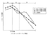
ここで、図9はロータリーバルブ600の開度と右回転用入力軸駆動部200の腕長さLとの関係を示すグラフであって、本実施の形態、後述する第2の実施の形態、右回転用入力軸駆動部200の各受圧面として図10に示す各受圧面48,49を採用した比較例、の三者を比較している。なお、ロータリバルブ600の開度は左切り側を正としている。また、図10に示す比較例における左回転用受圧面48および右回転用受圧面49は、それら各受圧面48,49が各左、右回転用ピストン120,220の進退方向で均一な傾斜角度をもって形成されているものである。
Here, FIG. 9 is a graph showing the relationship between the opening degree of the
つまり、図9に示すように、本実施の形態では、右回転用入力軸駆動部200をもって入力軸40に上記反力トルクを付与する際に、各右回転用ピストン220に各右回転用受圧面43の第2傾斜面43bをそれぞれ押圧させることで、ロータリーバルブ600の左切り側への開度が小さい第1領域S1において、その腕長さLが比較例よりも短くなるように設定し、上記反力トルクを比較例よりも軽減するようにしている。
That is, as shown in FIG. 9, in the present embodiment, when the reaction torque is applied to the
なお、ロータリーバルブ600の左切り側への開度が大きい第2領域S2においては、腕長さLを比較例よりも長くすることで、上記反力トルクが比較例よりも増大するように設定していて、これにより舵の切り過ぎを防止するようにしている。
In the second region S2 in which the opening degree of the
同様に、右方向操舵アシスト時には、右操舵用圧力室21の作動油も、油路31,33を介して左回転用トルク生成室D1に導入され、左回転用入力軸駆動部100が入力軸40に左回転方向、すなわち反操舵方向の比較的弱い反力トルクを付与することとなる。
Similarly, during the right steering assist, the hydraulic oil in the right
上述のように、通常操舵時において、右操舵用圧力室21の液圧が高い場合には、左回転用入力軸駆動部100によって入力軸40に左回転方向のトルクが付与される一方、第2圧力室22の液圧が高い場合には、右回転用入力軸駆動部200によって入力軸40に右回転方向のトルクが付与される。
As described above, when the hydraulic pressure in the right
このとき、両コントロールバルブ310,320は、車速センサ401によって検出された車速に応じて駆動され、入力軸40に車速に応じた反力トルクが付与されることとなる。
At this time, both
一方、視線認識カメラ402により運転者の居眠り状態またはわき見状態が検出された場合には、両コントロールバルブ310,320を交互に駆動し、両入力軸駆動部100,200の各トルク生成室D1,D2の液圧を交互に上下させる。これにより、入力軸40には左回転方向および右回転方向の操舵トルクが交互に付与され、その入力軸40が左右双方向の回転を繰り返して捩り方向に振動する。そして、入力軸40と接続するステアリングホイールSWが左右捩れ方向へと振動し、運転者に警告を発する。
On the other hand, when the driver's dozing state or side-viewing state is detected by the line-of-
また、白線認識カメラ403により車線逸脱状態が検出された場合には、両コントロールバルブ310,320を駆動して入力軸40に操舵トルクを付与し、フェイルセーフ部700の許容回動範囲内で入出力軸40,60を相対回転させる。これにより、ロータリーバルブ600を駆動してその開度を積極的に変化させ、いわゆる自動操舵制御を行い、車線復帰させる。
When the lane departure state is detected by the white
図11は右回転用入力軸駆動部200を示す断面図であって、その右回転用入力軸駆動部200がロータリーバルブ600を右切り側に回転させた状態を示している。
FIG. 11 is a cross-sectional view showing the right rotation input
詳細には、図11に示すように、例えば、車両が左側へ車線逸脱している場合には、右回転用コントロールバルブ320を駆動して右回転用ピストン220を入力軸40の径方向内側に前進させ、入力軸40に右回転方向の操舵トルクを付与する。なお、右回転用ピストン220が前進位置に位置する状態において、その右回転用ピストン220のピストン本体221と入力軸40との間に所定の隙間Gが確保されるようになっている。
Specifically, as shown in FIG. 11, for example, when the vehicle deviates to the left side, the right
そして、右回転用ピストン220が入力軸40の径方向内側に前進することで、その右回転用ピストン220は、右回転用受圧面43の第1傾斜面43aに当接するとともに、その第1傾斜面43aとの傾斜面接触をもって比較的強い右回転方向の操舵トルクを入力軸40に付与し、ロータリーバルブ600を右切り側に回転させる。これによって、右操舵用圧力室21の液圧を上昇させて右操舵方向へのアシスト力を発生させ、車両を右方向に回頭させることにより車線逸脱を回避する。
Then, when the
つまり、図9に示すように、ロータリーバルブ600が右切り側へ回転する第3領域S3において、ロータリーバルブ600を駆動するために十分な大きさの腕長さLを確保するように設定してある。
That is, as shown in FIG. 9, in the third region S3 in which the
同様に、右側へ車線逸脱している場合には、左回転用コントロールバルブ310を駆動することで左回転用入力軸駆動部100をもって左回転方向の操舵トルクを入力軸40に付与し、車両を左回頭させて車線逸脱を回避することとなる。
Similarly, when the vehicle is deviating to the right lane, driving the left
したがって、本実施の形態によれば、通常走行時に各左、右回転用ピストン120,220が各第2傾斜面42b,43bをそれぞれ押圧して反力トルクを発生する一方で、自動操舵制御時に各左、右回転用ピストン120,220が各第1傾斜面42b,43bを押圧して操舵トルクを発生させ、両入力軸駆動部100,200の発生するトルク特性を通常走行時と自動操舵制御時とで変化させているため、例えば車両の走行レーンからの逸脱を認識した場合等に、両入力軸駆動部100,200がロータリーバルブ600を作動させるに足る比較的強い操舵トルクを発生する一方で、通常走行時には比較的弱い適切な反力トルクを発生するように設定することができ、通常走行時における操舵フィーリングの悪化を防止しつつも、非常時には自動操舵制御を行うことが可能となる。
Therefore, according to the present embodiment, each of the left and right
また、各受圧面42,43のうち第1傾斜面42a,42bと第2傾斜面43a,43bとの境界に角部42c,43cを形成し、ロータリーバルブ600の上記中立時に、各左、右回転用ピストン120,220が各受圧面42,43のうち角部42c,43cに当接するように設定しているため、コントロールバルブ600の上記中立時から各左、右回転用ピストン120,220が進退方向に移動した際に、各受圧面42,43のうち第1傾斜面42a,43a上または第2傾斜面42b,43b上に各左、右回転用ピストン120,220が即座に移動し、両入力軸駆動部100,200の応答性が向上するメリットがある。
In addition,
なお、本実施の形態では、ロータリーバルブ600の上記中立時に、各左、右回転用ピストン120,220が各受圧面42,43の角部42c,43cに当接するように設定しているが、ロータリーバルブ600の上記中立時に、各左、右回転用ピストン120,220が各受圧面42,43の第1傾斜面42a,43aに当接するように設定することも可能である。この場合には、例えば直進中の小さい舵角の修正操舵時に、各左、右回転用ピストン120,220が各受圧面42,43の角部42c,43cに当接せず、引っ掛かり感の少ない良好な操舵フィーリングが得られるメリットがある。
In the present embodiment, when the
図12,13は上述した実施の形態における各受圧面42,43の変形例を示す図であって、右回転用入力軸駆動部200のうち上述した図7に相当する部位の拡大図である。なお、図12,13に図示された右回転用受圧面42について以下に説明するが、図12,13に示す変形例では、図示外の左回転用受圧面43も同様に構成されている。
12 and 13 are views showing modifications of the
図12に示す変形例は、右回転用受圧面42のうち第1傾斜面42aと第2傾斜面42bとの境界部に平面状の面取り部42dを形成したものであって、コントロールバルブ600の上記中立時から入出力軸40,60が相対回転した際に、各受圧面42,43のうち第1傾斜面42a,43a上または第2傾斜面42b,43b上に各左、右回転用ピストン120,220がスムーズに移動するようになる。
In the modification shown in FIG. 12, a planar chamfered
また、図13に示す変形例は、右回転用受圧面42のうち第1傾斜面42aと第2傾斜面42bとの境界部に曲面状の面取り部42eを形成したものであって、コントロールバルブ600の上記中立時から入出力軸40,60が相対回転した際に、各受圧面42,43のうち第1傾斜面42a,43a上または第2傾斜面42b,43b上に各左、右回転用ピストン120,220がよりスムーズに移動するようになる。
Further, the modification shown in FIG. 13 has a curved chamfered portion 42e formed at the boundary portion between the first
図14は上述した実施の形態における各左、右回転用ピストン120,220の変形例を示す図である。
FIG. 14 is a view showing a modification of the left and
図14に示す変形例は、各左、右回転用ピストン120,220のボール123,223をピストン本体121,221のボール受容部122,222に圧入したものであって、ボール123,223をピストン本体121、221に確実に保持させることができるメリットがある。
In the modification shown in FIG. 14, the
図15は本発明の第2の実施の形態を示す図であって、右回転用入力軸駆動部200のうち上述した図6に相当する部位の断面拡大図である。
FIG. 15 is a diagram showing a second embodiment of the present invention, and is an enlarged cross-sectional view of a portion corresponding to FIG. 6 described above in the input shaft drive unit for
図15に示す第2の実施の形態では、左回転用受圧面46および右回転用受圧面47を、それら各受圧面46,47のうち各左、右回転用ピストン120,220の押圧方向側に形成され、上記F−F線に対して傾斜した平面46a,47aと、各受圧面46,47のうち各左、右回転用ピストン120,220の反押圧方向側に形成され、平面46a,47aと入力軸セレーション部41の歯先面とを滑らかに連結する曲面46b,47bと、から構成したものである。換言すれば、各受圧面46,47の上記傾斜角度が各左、右回転用ピストン120,220の進退方向で連続的に変化している。
In the second embodiment shown in FIG. 15, the left rotation
この第2の実施の形態においても、図9に示すように、上記第1領域S1において、その腕長さLが比較例よりも小さくなるように設定し、上記反力トルクを比較例よりも軽減する一方で、上記第3領域S3において、ロータリーバルブ600を駆動するために十分な大きさの腕長さLを確保するように設定し、自動操舵制御を行うことを可能としていて、第1の実施の形態とほぼ同様の効果が得られる。
Also in the second embodiment, as shown in FIG. 9, in the first region S1, the arm length L is set to be smaller than that of the comparative example, and the reaction torque is set to be larger than that of the comparative example. On the other hand, in the third region S3, the arm length L that is large enough to drive the
1…パワーステアリング装置
10…油圧パワーシリンダ
21…右操舵用圧力室
22…左操舵用圧力室
40…入力軸
42…左回転用受圧面
42a…第1傾斜面
42b…第2傾斜面
42c…角部
42d…面取り部
42e…面取り部
43…右回転用受圧面
43a…第1傾斜面
43b…第2傾斜面
43c…角部
46…左回転用受圧面
47…右回転用傾斜面
50…トーションバー
60…出力軸
100…左回転用入力軸駆動部(左回転用入力軸駆動手段)
120…左回転用ピストン(入力軸駆動ピストン)
121…ピストン本体
122…ボール受容部
123…ボール
200…右回転用入力軸駆動部(右回転用入力軸駆動手段)
220…右回転用ピストン(入力軸駆動ピストン)
221…ピストン本体
222…ボール受容部
223…ボール
300…液圧制御部(液圧制御手段)
400…環境情報検出部(環境情報検出手段)
600…ロータリーバルブ
SW…ステアリングホイール
P…ポンプ
DESCRIPTION OF SYMBOLS 1 ...
120 ... Piston for left rotation (input shaft drive piston)
121 ...
220 ... Piston for right rotation (input shaft drive piston)
221 ...
400 ... Environmental information detection unit (environmental information detection means)
600 ... Rotary valve SW ... Steering wheel P ... Pump
Claims (20)
その入力軸とトーションバーを介して連結された出力軸と、
入出力軸間に形成され、それら入出力軸の相対回転に応じて操舵アシスト用のパワーシリンダのうち右操舵用圧力室および左操舵用圧力室にポンプからの液圧を選択的に供給するロータリーバルブと、
上記ポンプからの液圧により入力軸に右回転方向のトルクを付与する右回転用入力軸駆動手段と、
上記ポンプからの液圧により入力軸に左回転方向のトルクを付与する左回転用入力軸駆動手段と、
車両、運転者および道路のうち少なくともいずれかの情報を検出する環境情報検出手段と、
その環境情報検出手段の出力信号に基づいて上記両入力軸駆動手段に供給される液圧を制御する液圧制御手段と、
を備えていて、
上記液圧制御手段は、運転者が操舵を行った際に上記両入力軸駆動手段をもって入力軸に反操舵方向の反力トルクを与える一方で、上記環境情報検出手段の出力信号に応じて上記両入力軸駆動手段により入力軸に操舵トルクを与えてロータリーバルブを駆動するようになっているパワーステアリング装置であって、
上記両入力軸駆動手段は、入力軸の外周に形成された受圧面と、出力軸内にその出力軸の径方向で進退可能に設けられ、上記ポンプからの液圧をもって受圧面を押圧する入力軸駆動ピストンと、をそれぞれ備え、入力軸駆動ピストンと受圧面との傾斜面接触をもって入力軸にトルクを付与するようになっていて、入力軸駆動ピストンの進退方向に対する受圧面の傾斜角度が入力軸駆動ピストンの進退方向で変化していることを特徴とするパワーステアリング装置。 An input shaft connected to a steering wheel;
An output shaft connected to the input shaft via a torsion bar;
A rotary that is formed between the input and output shafts and selectively supplies the hydraulic pressure from the pump to the right steering pressure chamber and the left steering pressure chamber of the steering assist power cylinder according to the relative rotation of the input and output shafts. A valve,
A right rotation input shaft driving means for applying torque in the right rotation direction to the input shaft by the hydraulic pressure from the pump;
A left rotation input shaft drive means for applying a torque in the left rotation direction to the input shaft by the hydraulic pressure from the pump;
Environmental information detection means for detecting information of at least one of a vehicle, a driver and a road;
Hydraulic pressure control means for controlling the hydraulic pressure supplied to both the input shaft driving means based on the output signal of the environmental information detection means;
With
The hydraulic pressure control means gives the reaction torque in the anti-steering direction to the input shaft by the both input shaft driving means when the driver performs steering, while the hydraulic pressure control means responds to the output signal of the environmental information detection means. A power steering device configured to drive a rotary valve by applying steering torque to an input shaft by both input shaft driving means,
The both input shaft driving means are provided with a pressure receiving surface formed on the outer periphery of the input shaft and an input shaft that can move forward and backward in the radial direction of the output shaft in the output shaft and presses the pressure receiving surface with the hydraulic pressure from the pump. Each of which has a shaft drive piston, and applies torque to the input shaft by contacting the inclined surface of the input shaft drive piston and the pressure receiving surface, and the inclination angle of the pressure receiving surface with respect to the advancing / retreating direction of the input shaft drive piston A power steering device characterized by changing in the advancing and retracting direction of the shaft drive piston.
トーションバーが捩じれていないロータリーバルブの中立時において、上記両入力軸駆動手段の入力軸駆動ピストンが受圧面のうち第1傾斜面にそれぞれ当接していることを特徴とする請求項1に記載のパワーステアリング装置。 The pressure receiving surfaces of the both input shaft driving means are formed on the first inclined surface formed on the pressure direction side of the input shaft driving piston among the pressure receiving surfaces and on the side opposite to the pressure direction of the input shaft driving piston among the pressure receiving surfaces. And a second inclined surface in which the inclination angle is set larger than the first inclined surface,
2. The input shaft drive pistons of the two input shaft drive means are in contact with the first inclined surfaces of the pressure receiving surfaces when the rotary valve is not twisted and is neutral. Power steering device.
トーションバーが捩じれていないロータリーバルブの中立時において、上記両入力軸駆動手段の入力軸駆動ピストンが受圧面のうち第1傾斜面と第2傾斜面との境界部にそれぞれ当接していることを特徴とする請求項1に記載のパワーステアリング装置。 The pressure receiving surfaces of the both input shaft driving means are formed on the first inclined surface formed on the pressure direction side of the input shaft driving piston among the pressure receiving surfaces and on the side opposite to the pressure direction of the input shaft driving piston among the pressure receiving surfaces. And a second inclined surface in which the inclination angle is set larger than the first inclined surface,
When the rotary valve in which the torsion bar is not twisted is neutral, the input shaft drive pistons of the input shaft drive means are in contact with the boundary between the first inclined surface and the second inclined surface of the pressure receiving surfaces. The power steering device according to claim 1, wherein
上記両入力軸駆動手段のうち入力軸駆動ピストンのボールの外径がピストン本体のうちボール受容部の内径よりも小さくなるようにそれぞれ設定されていることを特徴とする請求項1〜8のいずれかに記載のパワーステアリング装置。 The input shaft drive pistons of both the input shaft drive means include a piston main body having a concave ball receiving portion formed on the pressure receiving surface side, and a ball received by the ball receiving portion of the piston main body and in contact with the pressure receiving surface. Each is composed of
9. The input shaft drive piston of the two input shaft drive means is set such that the outer diameter of the ball of the input shaft drive piston is smaller than the inner diameter of the ball receiving portion of the piston body. A power steering device according to claim 1.
上記両入力軸駆動手段のうち入力軸駆動ピストンのボールがピストン本体のボール受容部にそれぞれ圧入されていることを特徴とする請求項1〜8のいずれかに記載のパワーステアリング装置。 The input shaft drive pistons of both the input shaft drive means include a piston main body having a concave ball receiving portion formed on the pressure receiving surface side, and a ball received by the ball receiving portion of the piston main body and in contact with the pressure receiving surface. Each is composed of
The power steering apparatus according to any one of claims 1 to 8, wherein a ball of an input shaft driving piston is press-fitted into a ball receiving portion of a piston body among the both input shaft driving means.
その入力軸とトーションバーを介して連結された出力軸と、
入出力軸間に形成され、それら入出力軸の相対回転に応じて操舵アシスト用のパワーシリンダのうち右操舵用圧力室および左操舵用圧力室にポンプからの液圧を選択的に供給するロータリーバルブと、
上記ポンプからの液圧により入力軸に右回転方向のトルクを付与する右回転用入力軸駆動手段と、
上記ポンプからの液圧により入力軸に左回転方向のトルクを付与する左回転用入力軸駆動手段と、
車両、運転者および道路のうち少なくともいずれかの情報を検出する環境情報検出手段と、
その環境情報検出手段の出力信号に基づいて上記両入力軸駆動手段に供給される液圧を制御する液圧制御手段と、
を備えていて、
上記液圧制御手段は、運転者が操舵を行った際に上記両入力軸駆動手段をもって入力軸に反操舵方向の反力トルクを与える一方で、上記環境情報検出手段の出力信号に応じて上記両入力軸駆動手段により入力軸に操舵トルクを与えてロータリーバルブを駆動するようになっているパワーステアリング装置であって、
上記両入力軸駆動手段は、上記入力軸の外周に形成された受圧面と、出力軸内にその出力軸の径方向で進退可能に設けられ、上記ポンプからの液圧をもって受圧面を押圧する入力軸駆動ピストンと、をそれぞれ備えているとともに、
受圧面は、入力軸駆動ピストンの進退方向に対して傾斜した第1傾斜面と、入力軸駆動ピストンの進退方向に対する傾斜角度を第1傾斜面よりも大きく設定した第2傾斜面と、をそれぞれ有していて、
入力軸に上記反力トルクを与える際に入力軸駆動ピストンが受圧面のうち第2傾斜面を押圧する一方で、入力軸に上記操舵トルクを与える際に入力軸駆動ピストンが受圧面のうち第1傾斜面を押圧するようになっていることを特徴とするパワーステアリング装置。 An input shaft connected to a steering wheel;
An output shaft connected to the input shaft via a torsion bar;
A rotary that is formed between the input and output shafts and selectively supplies the hydraulic pressure from the pump to the right steering pressure chamber and the left steering pressure chamber of the steering assist power cylinder according to the relative rotation of the input and output shafts. A valve,
A right rotation input shaft driving means for applying torque in the right rotation direction to the input shaft by the hydraulic pressure from the pump;
A left rotation input shaft drive means for applying a torque in the left rotation direction to the input shaft by the hydraulic pressure from the pump;
Environmental information detection means for detecting information of at least one of a vehicle, a driver and a road;
Hydraulic pressure control means for controlling the hydraulic pressure supplied to both the input shaft driving means based on the output signal of the environmental information detection means;
With
The hydraulic pressure control means gives the reaction torque in the anti-steering direction to the input shaft by the both input shaft driving means when the driver performs steering, while the hydraulic pressure control means responds to the output signal of the environmental information detection means. A power steering device configured to drive a rotary valve by applying steering torque to an input shaft by both input shaft driving means,
The input shaft drive means is provided with a pressure receiving surface formed on the outer periphery of the input shaft, and is provided in the output shaft so as to be able to advance and retreat in the radial direction of the output shaft, and presses the pressure receiving surface with the hydraulic pressure from the pump. Each having an input shaft drive piston,
The pressure receiving surface includes a first inclined surface that is inclined with respect to the advancing / retreating direction of the input shaft driving piston, and a second inclined surface in which an inclination angle with respect to the advancing / retreating direction of the input shaft driving piston is set larger than that of the first inclined surface. Have
The input shaft driving piston presses the second inclined surface of the pressure receiving surface when the reaction torque is applied to the input shaft, while the input shaft driving piston is the first of the pressure receiving surfaces when the steering torque is applied to the input shaft. 1. A power steering device characterized by pressing one inclined surface.
その入力軸とトーションバーを介して連結された出力軸と、
入出力軸間に形成され、それら入出力軸の相対回転に応じて操舵アシスト用のパワーシリンダのうち右操舵用圧力室および左操舵用圧力室にポンプからの液圧を選択的に供給するロータリーバルブと、
上記ポンプからの液圧により入力軸に右回転方向のトルクを付与する右回転用入力軸駆動手段と、
上記ポンプからの液圧により入力軸に左回転方向のトルクを付与する左回転用入力軸駆動手段と、
車両、運転者および道路のうち少なくともいずれかの情報を検出する環境情報検出手段と、
その環境情報検出手段の出力信号に基づいて上記両入力軸駆動手段に供給される液圧を制御する液圧制御手段と、
を備えていて、
上記液圧制御手段は、運転者が操舵を行った際に上記両入力軸駆動手段をもって入力軸に反操舵方向の反力トルクを与える一方で、上記環境情報検出手段の出力信号に応じて上記両入力軸駆動手段により入力軸に操舵トルクを与えてロータリーバルブを駆動するようになっているパワーステアリング装置であって、
上記両入力軸駆動手段は、上記入力軸の外周に形成された受圧面と、上記出力軸内にその出力軸の径方向で進退可能に設けられ、上記ポンプからの液圧をもって上記受圧面を押圧する入力軸駆動ピストンと、をそれぞれ備えているとともに、
上記受圧面は、その受圧面のうち入力軸駆動ピストンの押圧方向側に形成され、入力軸駆動ピストンの進退方向に対して傾斜した第1傾斜面と、受圧面のうち入力軸駆動ピストンの反押圧方向側に形成され、入力軸駆動ピストンの進退方向に対する傾斜角度を第1傾斜面よりも大きく設定した第2傾斜面と、をそれぞれ有していることを特徴とするパワーステアリング装置。 An input shaft connected to a steering wheel;
An output shaft connected to the input shaft via a torsion bar;
A rotary that is formed between the input and output shafts and selectively supplies the hydraulic pressure from the pump to the right steering pressure chamber and the left steering pressure chamber of the steering assist power cylinder according to the relative rotation of the input and output shafts. A valve,
A right rotation input shaft driving means for applying torque in the right rotation direction to the input shaft by the hydraulic pressure from the pump;
A left rotation input shaft drive means for applying a torque in the left rotation direction to the input shaft by the hydraulic pressure from the pump;
Environmental information detection means for detecting information of at least one of a vehicle, a driver and a road;
Hydraulic pressure control means for controlling the hydraulic pressure supplied to both the input shaft driving means based on the output signal of the environmental information detection means;
With
The hydraulic pressure control means gives the reaction torque in the anti-steering direction to the input shaft by the both input shaft driving means when the driver performs steering, while the hydraulic pressure control means responds to the output signal of the environmental information detection means. A power steering device configured to drive a rotary valve by applying steering torque to an input shaft by both input shaft driving means,
The both input shaft driving means are provided with a pressure receiving surface formed on the outer periphery of the input shaft, and provided in the output shaft so as to be able to advance and retreat in the radial direction of the output shaft. Each having an input shaft driving piston to be pressed,
The pressure receiving surface is formed on the pressure direction side of the pressure receiving surface of the input shaft driving piston, and is inclined with respect to the advancing / retreating direction of the input shaft driving piston, and the pressure receiving surface is opposite to the input shaft driving piston. And a second inclined surface that is formed on the pressing direction side and has an inclination angle with respect to the advancing / retreating direction of the input shaft drive piston larger than that of the first inclined surface.
Priority Applications (4)
| Application Number | Priority Date | Filing Date | Title |
|---|---|---|---|
| JP2007172169A JP2009006948A (en) | 2007-06-29 | 2007-06-29 | Power steering device |
| US12/138,842 US20090000855A1 (en) | 2007-06-29 | 2008-06-13 | Power steering device |
| DE102008030500A DE102008030500A1 (en) | 2007-06-29 | 2008-06-27 | Power steering device |
| CNA2008101289723A CN101397030A (en) | 2007-06-29 | 2008-06-27 | Power steering device |
Applications Claiming Priority (1)
| Application Number | Priority Date | Filing Date | Title |
|---|---|---|---|
| JP2007172169A JP2009006948A (en) | 2007-06-29 | 2007-06-29 | Power steering device |
Publications (1)
| Publication Number | Publication Date |
|---|---|
| JP2009006948A true JP2009006948A (en) | 2009-01-15 |
Family
ID=40121689
Family Applications (1)
| Application Number | Title | Priority Date | Filing Date |
|---|---|---|---|
| JP2007172169A Pending JP2009006948A (en) | 2007-06-29 | 2007-06-29 | Power steering device |
Country Status (4)
| Country | Link |
|---|---|
| US (1) | US20090000855A1 (en) |
| JP (1) | JP2009006948A (en) |
| CN (1) | CN101397030A (en) |
| DE (1) | DE102008030500A1 (en) |
Families Citing this family (3)
| Publication number | Priority date | Publication date | Assignee | Title |
|---|---|---|---|---|
| JP5498421B2 (en) * | 2011-03-24 | 2014-05-21 | 日立オートモティブシステムズステアリング株式会社 | Integral power steering system |
| TWI494238B (en) * | 2013-01-16 | 2015-08-01 | Kwang Yang Motor Co | Electron powered auxiliary steering device with pre-twisting function |
| CN103963827B (en) * | 2013-01-28 | 2017-03-01 | 光阳工业股份有限公司 | There is the electric power-assisted transfer of pretwist function |
Citations (3)
| Publication number | Priority date | Publication date | Assignee | Title |
|---|---|---|---|---|
| JPH06340262A (en) * | 1993-05-31 | 1994-12-13 | Mitsubishi Motors Corp | Vehicle with auxiliary steering gear |
| JPH09254801A (en) * | 1996-03-26 | 1997-09-30 | Toyota Motor Corp | Vehicular steering control device |
| JP2005119649A (en) * | 2003-09-24 | 2005-05-12 | Koyo Seiko Co Ltd | Hydraulic power steering apparatus |
Family Cites Families (15)
| Publication number | Priority date | Publication date | Assignee | Title |
|---|---|---|---|---|
| JPH082757B2 (en) * | 1988-11-15 | 1996-01-17 | 光洋精工株式会社 | Power steering device |
| JPH03258658A (en) | 1990-03-06 | 1991-11-18 | Jidosha Kiki Co Ltd | Power steering device |
| US5190119A (en) * | 1990-04-16 | 1993-03-02 | Koyo Seiko Co., Ltd. | Hydraulic power steering device responsive to speed of vehicle |
| US5392875A (en) * | 1991-12-23 | 1995-02-28 | Ford Motor Company | Hydraulic reaction variable assist power steering system |
| JP3469965B2 (en) * | 1994-10-04 | 2003-11-25 | 光洋精工株式会社 | Variable throttle valve and hydraulic power steering device |
| JP3547558B2 (en) * | 1995-10-25 | 2004-07-28 | 光洋精工株式会社 | Power steering device |
| DE19616439C1 (en) * | 1996-04-25 | 1997-12-11 | Daimler Benz Ag | Reaction arrangement on a servo valve arrangement |
| JP3146981B2 (en) * | 1996-07-09 | 2001-03-19 | トヨタ自動車株式会社 | Power steering device |
| JPH11152053A (en) * | 1997-11-25 | 1999-06-08 | Toyota Motor Corp | Power steering gear |
| DE19829531A1 (en) * | 1998-07-02 | 2000-01-05 | Zahnradfabrik Friedrichshafen | Power steering with hydraulic power assistance |
| JP4351583B2 (en) * | 2004-05-21 | 2009-10-28 | 株式会社日立製作所 | Power steering device |
| JP2007045386A (en) * | 2004-10-13 | 2007-02-22 | Jtekt Corp | Hydraulic power steering apparatus |
| JP4577512B2 (en) * | 2005-10-28 | 2010-11-10 | 株式会社ジェイテクト | Hydraulic power steering device |
| JP4766383B2 (en) | 2005-12-20 | 2011-09-07 | 独立行政法人海洋研究開発機構 | Particle data calculation program, particle data calculation apparatus and method |
| JP2009096428A (en) * | 2007-10-19 | 2009-05-07 | Hitachi Ltd | Power steering system |
-
2007
- 2007-06-29 JP JP2007172169A patent/JP2009006948A/en active Pending
-
2008
- 2008-06-13 US US12/138,842 patent/US20090000855A1/en not_active Abandoned
- 2008-06-27 CN CNA2008101289723A patent/CN101397030A/en active Pending
- 2008-06-27 DE DE102008030500A patent/DE102008030500A1/en not_active Ceased
Patent Citations (3)
| Publication number | Priority date | Publication date | Assignee | Title |
|---|---|---|---|---|
| JPH06340262A (en) * | 1993-05-31 | 1994-12-13 | Mitsubishi Motors Corp | Vehicle with auxiliary steering gear |
| JPH09254801A (en) * | 1996-03-26 | 1997-09-30 | Toyota Motor Corp | Vehicular steering control device |
| JP2005119649A (en) * | 2003-09-24 | 2005-05-12 | Koyo Seiko Co Ltd | Hydraulic power steering apparatus |
Also Published As
| Publication number | Publication date |
|---|---|
| DE102008030500A1 (en) | 2009-01-15 |
| CN101397030A (en) | 2009-04-01 |
| US20090000855A1 (en) | 2009-01-01 |
Similar Documents
| Publication | Publication Date | Title |
|---|---|---|
| US7819217B2 (en) | Power steering apparatus, method of controlling the same and method of assembling the same | |
| JP2008037192A (en) | Power steering device | |
| JP2016150645A (en) | Power steering device | |
| US20090101430A1 (en) | Power steering apparatus | |
| JP2009006948A (en) | Power steering device | |
| JP2007168674A (en) | Power steering system and control method thereof | |
| JP3027783B2 (en) | Steering gear | |
| JP2007045386A (en) | Hydraulic power steering apparatus | |
| JP5641394B2 (en) | Power steering device | |
| JPH0581464B2 (en) | ||
| JP5573012B2 (en) | Oldham Joint | |
| JP2002029430A (en) | Steering system for vehicle | |
| JP5679320B2 (en) | Automatic steering control device and program | |
| JP2978338B2 (en) | Steering gear | |
| JP5964775B2 (en) | Power steering device | |
| JP2850146B2 (en) | Integral type power steering device | |
| JP2010137603A (en) | Power steering device | |
| JPH115552A (en) | Steering device for vehicle | |
| JP2008168692A (en) | Power steering device | |
| WO2022264890A1 (en) | Steering device | |
| JP3557487B2 (en) | Hydraulic control valve | |
| JP2005082007A (en) | Power steering device | |
| JP2004284411A (en) | Reduction gear ratio variable type power steering device | |
| JP2010132054A (en) | Steering control device | |
| KR101143752B1 (en) | Pinion valve assembly for hydraulic power steering system |
Legal Events
| Date | Code | Title | Description |
|---|---|---|---|
| A621 | Written request for application examination |
Free format text: JAPANESE INTERMEDIATE CODE: A621 Effective date: 20090814 |
|
| A711 | Notification of change in applicant |
Free format text: JAPANESE INTERMEDIATE CODE: A712 Effective date: 20090922 |
|
| RD03 | Notification of appointment of power of attorney |
Free format text: JAPANESE INTERMEDIATE CODE: A7423 Effective date: 20090922 |
|
| A977 | Report on retrieval |
Free format text: JAPANESE INTERMEDIATE CODE: A971007 Effective date: 20110512 |
|
| A131 | Notification of reasons for refusal |
Free format text: JAPANESE INTERMEDIATE CODE: A131 Effective date: 20120424 |
|
| A02 | Decision of refusal |
Free format text: JAPANESE INTERMEDIATE CODE: A02 Effective date: 20120904 |