JP3557487B2 - Hydraulic control valve - Google Patents
Hydraulic control valve Download PDFInfo
- Publication number
- JP3557487B2 JP3557487B2 JP14645195A JP14645195A JP3557487B2 JP 3557487 B2 JP3557487 B2 JP 3557487B2 JP 14645195 A JP14645195 A JP 14645195A JP 14645195 A JP14645195 A JP 14645195A JP 3557487 B2 JP3557487 B2 JP 3557487B2
- Authority
- JP
- Japan
- Prior art keywords
- oil
- groove
- grooves
- oil supply
- valve body
- Prior art date
- Legal status (The legal status is an assumption and is not a legal conclusion. Google has not performed a legal analysis and makes no representation as to the accuracy of the status listed.)
- Expired - Fee Related
Links
Images


Landscapes
- Power Steering Mechanism (AREA)
Description
【0001】
【産業上の利用分野】
本発明は、バルブボディーとバルブスプールとの相対角変位に応じて油圧の給排制御を行う油圧制御弁に関し、特に、自動車に装備される油圧式の動力舵取装置に操舵補助用の油圧アクチュエータへの送給油圧を舵輪操作に応じて制御すべく用いられる油圧制御弁に関する。
【0002】
【従来の技術】
油圧式の動力舵取装置は、自動車の舵取機構中に配した複動式の油圧シリンダ(パワーシリンダ)等の油圧アクチュエータの発生力により舵取りを補助し、舵輪(ステアリングホィール)の操作に要する運転者の労力負担を軽減して、快適な操舵感覚を得ようとするものである。
【0003】
操舵補助用の油圧アクチュエータには、例えば、パワーシリンダにおける両油室に連なる送油ポート等、左右両方向への操舵補助のための2か所の送油先が設定されており、前記動力舵取装置は、これらの送油先と、エンジンにて駆動される油圧ポンプ(油圧源)及び作動油を収納する油タンク(排油先)との間に、舵輪に加わる操舵トルクの方向及び大きさに応じて油圧の給排制御を行う油圧制御弁を配してなる。
【0004】
この種の油圧制御弁としては、舵輪の回転を直接的に利用する回転式の油圧制御弁が広く用いられている。これは、舵輪に連なる入力軸と舵取機構に連なる出力軸とを細径のトーションバーを介して同軸的に連結し、一方の連結端に係合された筒形のバルブボディーの内側に、他方の連結端に一体的に形成したバルブスプールを同軸上での相対回転自在に嵌め合わせた構成となっている。
【0005】
両者の嵌合周面、即ち、バルブボディーの内周面とバルブスプールの外周面とには、軸長方向に延びる各複数の油溝が周方向に等配をなして並設されており、これらの油溝は、嵌合周上にて周方向に千鳥配置されて、相隣する油溝間に前記相対角変位に応じて絞り面積を変える複数の絞り部を形成しており、一方(バルブボディー又はバルブスプール)の側の複数の油溝の内、一つ置きに位置する半数は、油圧ポンプから作動油圧が供給される給油溝とされ、残りの半数は、排油先となる油タンクに連なる排油溝とされている。また、これらの給油溝と排油溝との間の他方(バルブスプール又はバルブボディー)の側の油溝は、前記2か所の送油先に交互に連通され、これらへの送油のための送油溝を構成している。
【0006】
図6は、ラック・ピニオン式の動力舵取装置の構成を示す模式図である。ラック・ピニオン式の舵取機構は、舵輪1の下側に同軸的に連設された舵輪軸10の下端にピニオン11を連設し、該ピニオン11を車体の前部に左右方向に延設されたラック軸12の中途部に噛合せしめ、舵取りのための舵輪1の回転をラック軸12の軸方向の摺動に変換し、該ラック軸12の両端に各別のナックルアーム14,14を介して連結された左右一対の操向車輪(一般的には前輪)13,13の向きを変え、舵取りを行わせる構成となっている。
【0007】
このようなラック・ピニオン式の舵取機構において、操舵補助用のパワーシリンダSは、前記ラック軸12に軸方向の摺動力を加えるべく、該ラック軸12の中途に構成されており、左右両方向への操舵補助のための2か所の送油先として、左右の油室に夫々連通する送油ポートS1 ,S2 が設定してある。
【0008】
一方、このパワーシリンダSへの送給油圧を制御する油圧制御弁Vは、舵輪1の回転を利用すべく舵輪軸10の下部に連結された入力軸2と、ピニオン11と一体化された出力軸2′との間に構成され、内部において前記一対の送油溝の夫々に連通するシリンダポートV1 ,V2 を備えており、これらと前記送油ポートS1 ,S2 とが各別の送油管P1 ,P2 を介して接続されている。また油圧制御弁Vには、内部において前記給油溝及び前記排油溝に夫々連通するポンプポートV3 及びタンクポートV4 を備えており、前者は油圧源となる油圧ポンプに、後者は排油先となる油タンクに夫々接続されている。
【0009】
なお、油圧制御弁VのシリンダポートV1 ,V2 と対応する送油溝とは、筒形をなすバルブボディーの周壁を該当する周方向位置にて貫通する各別の送油孔により連通され、またポンプポートV3 と給油溝とは、同じくバルブボディーを貫通する各別の導油孔により連通されている。更に、タンクポートV4 と排油溝との連通は、前記トーションバーの挿通のためにバルブスプールの軸心部に形成された中空部を利用して行われ、送油溝に受け入れた戻り油を、夫々の対応位置にてバルブスプールを貫通する導油孔により前記中空部に集め、更に、バルブスプールの該当位置を貫通する導油孔により、バルブボディーの一側に設けた排油室に集め、この排油室に開口する前記タンクポートV4 を経て排出する構成としてある。
【0010】
而して、舵輪1に操舵トルクが加えられた場合、油圧制御弁Vの内部においてバルブボディーとバルブスプールとの間に相対角変位が生じ、両者の嵌合周上に並ぶ各油溝間の絞り面積が変化して、ポンプポートV3 を経て給油溝に供給される油圧は、絞り面積を増した側の絞り部を経て同側に相隣する送油溝に導入されて、対応するシリンダポートV1 (又はV2 )を経て送油管P1 (又はP2 )内に送出され、一方の送油ポートS1 (又はS2 )を経てパワーシリンダSの対応する油室内に送給される。これによりパワーシリンダSは、他方の油室との間に生じる圧力差に応じた油圧力を発生し、この油圧力がラック軸12に加えられて、前述の如く行われる舵取りが補助される。
【0011】
【発明が解決しようとする課題】
以上の如く構成された従来の動力舵取装置において、舵輪1の左右両方向の操作に応じて前記シリンダポートV1 及びV2 のいずれが送油に関わるかは、油圧制御弁Vの内部構成、具体的には、ポンプポートV3 と連通する給油溝の両側における一対の送油溝と前記シリンダポートV1 及びV2 との連通態様によって定まる。図においては、舵輪1の左向きの操作に応じてシリンダポートV1 (下位置にある)からの送油がなされるように構成してあり、この送油が、送油管P1 及び送油ポートS1 を経てパワーシリンダSに与えられる結果、該パワーシリンダSは、図中に矢符にて示す方向にラック軸12を押圧することになり、車両の進行方向(図の下方向)に対して左向きの操舵が補助される。
【0012】
ところが、以上の構成は、図6(a)に示す如く、前記進行方向に向かって右位置に舵輪1を備える自動車、所謂、右ハンドル車におけるものである。一方、諸外国においては、左位置に舵輪1を備える左ハンドル車が主流となっており、このような左ハンドル車においては、図6(b)に示す如く、ラック軸12の軸方向において、舵輪軸10の下端のピニオン11の噛合位置とパワーシリンダSとの相対位置が、図6(a)に示す右ハンドル車の場合のそれと逆転する。
【0013】
従って、このような左ハンドル車において、右ハンドル車と同一構成、即ち、舵輪1の左向きの操作に応じて下位置にあるシリンダポートV1 からの送油がなされる構成とした油圧制御弁Vを用い、この送油に応じて、図6(a)の場合と同方向の操舵補助力が得られるようにするには、図6(b)に示す如く、前記シリンダポートV1 に接続された送油管P1 を油圧制御弁Vから離れた側の送油ポートS2 に接続せねばならず、油圧制御弁VのシリンダポートV1 ,V2 と、パワーシリンダSの送油ポートS1 ,S2 との接続関係が、図6(a)における接続関係と相違することになる。
【0014】
そこで、車両への組み込み段階において行われる前記送油管P1 ,P2 の接続違いを防止するために、望ましくは、左ハンドル車及び右ハンドル車の夫々に対して内部における連通構成の異なる2種の油圧制御弁Vを用意する必要があり、また、同一構成の油圧制御弁Vを左右ハンドル車に兼用する場合には、例えば、左、右ハンドル車の場合の接続関係を示す付箋を取り付ける等、接続違いの防止対策が必要となるという難点があった。
【0015】
このような問題は、他の形式の動力舵取装置においても同様に発生する。図7は、ボールねじ式の動力舵取装置の構成を示す模式図であり、(a)には、右ハンドル車における構成が、(b)には、左ハンドル車における構成が夫々示されている。
【0016】
ボールねじ式の舵取機構は、舵輪軸10の下端に連結した入力軸2をボールねじ機構を内蔵する伝動ハウジング15中に延設し、該伝動ハウジング15内にて入力軸2の回転に伴って生じるボールナットの軸長方向の移動をピットマンアーム16の揺動として伝動ハウジング15外に取り出し、該ピットマンアーム16に連結リンク17を介して連結された一方のナックルアーム14を回動させ、またこの回動を、タイロッド18により他方のナックルアーム14に伝えて、両ナックルアーム14,14に付設された左右の操向車輪13,13の向きを変え、舵取りを行わせる構成となっている。
【0017】
操舵補助用のパワーシリンダSは、伝動ハウジング15の内部をシリンダ室とし、前記ボールナットをピストンとして構成されており、左右両方向への操舵補助のための2か所の送油先として、前記ボールナットの上下の油室が設定されている。このパワーシリンダSへの送給油圧を制御する油圧制御弁Vは、伝動ハウジング15内への入力軸2の延設端とボールねじ軸とをトーションバーを介して連結し、この連結部分に、前記パワーシリンダSの一側に並べて設けてあり、前記一対の送油溝の夫々と、送油先となるパワーシリンダSの上下の油室とは、一方又は両方に対して、伝動ハウジング15の内部空間を利用して連結され、送油管を省略することができる。
【0018】
さて、このように構成されたボールねじ式の動力舵取装置において、左右両側のナックルアーム14,14とピットマンアーム16との連結態様は、左,右ハンドル車において異なり、図7(a)に示す右ハンドル車においてピットマンアーム16は、車両の進行方向(図の下方向)に対して右側のナックルアーム14に連結されるているのに対し、図7(b)に示す左ハンドル車においてピットマンアーム16は、左側のナックルアーム14に連結されている。
【0019】
これにより、例えば、操向車輪13,13を左向きに転舵するためにピットマンアーム16の揺動は、図7(a)に示す右ハンドル車においては、連結リンク17に後方への引き力を加える方向に生じるのに対し、図7(b)に示す左ハンドル車においては、連結リンク17に前方への押し力を加える方向に生じることになる。従って、伝動ハウジング15内に構成されたパワーシリンダSにおいては、左向きの操舵補助のために、右ハンドル車では、下側の油室への油圧の送給が必要となるのに対し、左ハンドル車では逆に、上側の油室への油圧の送給が必要となり、このような送給は、内部における連通構成を同一とした油圧制御弁Vにより行わせることはできない。
【0020】
更に、ボールねじ式の動力舵取装置においては、前述した如く、パワーシリンダSの両油室と油圧制御弁Vの一対の送油溝の夫々との連通のための送油管の一方又は両方が省略されることが多く、前述した問題に送油管の接続替えにより対応することができず、右ハンドル車用及び、左ハンドル車用として、連通構成の異なる2種の油圧制御弁Vを用意する必要がある。
【0021】
本発明は斯かる事情に鑑みてなされたものであり、組み立て段階でのわずかな組み替え操作により、内部における連通構成を変更し、送油先を逆転することができ、動力舵取装置用として用いる場合に、右ハンドル車及び左ハンドル車の双方への適用が可能となる油圧制御弁を提供することを目的とする。
【0022】
【課題を解決するための手段】
本発明に係る油圧制御弁は、筒形をなすバルブボディーの内側に同軸上での相対角変位可能にバルブスプールを嵌め合わせ、両者の嵌合周上に並ぶ各複数の油溝を周方向に千鳥配置してなり、一方の側の複数の油溝を2か所の送油先に交互に連通させた送油溝とし、他方の側の複数の油溝を、油圧源及び排油先に交互に連なる給油溝及び排油溝として、前記給油溝に供給される圧油を、該給油溝の両側にて前記相対角変位に伴って生じる絞り面積の変化に応じて振り分け、一側に相隣する送油溝を経て前記送油先の一方に送給する油圧制御弁において、前記嵌合周面に周設され、前記給油溝の夫々を相互に連通する環状溝と、前記バルブボディーの周壁を貫通し、前記油圧源からの供給油圧を前記環状溝に導入する導油孔とを具備することを特徴とする。
【0023】
【作用】
本発明においては、油圧源からの供給油圧を、バルブボディーを貫通する導油孔を経てバルブスプールとの嵌合周面に周設した環状溝に導入し、この環状溝に連通する給油溝に供給して、該給油溝の両側の絞り部における絞り面積の変化に応じて夫々の側の送油溝に振り分け、バルブボディーを貫通する各別の送油孔を経て夫々に対応する送油先に送給する。相対角変位の方向と送油先との対応関係を逆転する場合には、バルブボディーとバルブスプールとを、相隣する送油溝間の中心角度分だけ周方向の相対位置をずらせて組み立て、一方の送油溝に対応すべき送油孔を他方の送油溝に対応させる。このとき、導油孔による油圧の供給位置も変化するが、該導油孔は周方向に連続する環状溝に連通しており、該環状溝に連通する給油溝と、両側の送油溝に連通する送油先との対応関係のみが逆転する。
【0024】
【実施例】
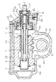
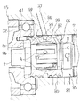
以下本発明をその実施例を示す図面に基づいて詳述する。図1は、本発明に係る油圧制御弁を備えるボールねじ式の動力舵取装置の要部を示す縦断面図、図2は、油圧制御弁の構成位置近傍の拡大図である。
【0025】
図中15は、伝動ハウジングであり、該伝動ハウジング15の内部には、図7に示す如く、舵輪軸10の下端に連結された入力軸2が、一側(上側)から適長侵入させてあり、回動自在に支持されている。伝動ハウジング15の内部には、高精度に仕上げた円形の内周面を有してシリンダ室3が形成されており、該シリンダ室3の中途部内側を臨む態様にギヤ室30が連設されている。
【0026】
シリンダ室3の軸心部には、ボールねじ軸4が、これの中途部に一体的に構成された玉軸受32により回動自在に枢支されている。またギヤ室30には、前記ボールねじ軸4と略直交する態様にクロスシャフト5が枢支されており、ギヤ室30の外側へのクロスシャフト5の突出端は、この回転に応じた舵取りを行わせるべく、ピットマンアーム16及び連結リンク17(図7参照)を介して舵取機構に連結されている。
【0027】
シリンダ室3の内部には、軸長方向への摺動自在にピストン6が嵌挿されている。該ピストン6は、円筒形の部材であり、シリンダ室3の内部は、ピストン6の一側(下側)外周に巻装されたシール部材60により液密に封止された上下一対の油室Sa ,Sb に分割されており、これらの油室Sa ,Sb への油圧送給によりピストン6を摺動させる構成となっている。
【0028】
また、ピストン6の内周には、前記ボールねじ軸4と多数のボール40,40…を介して螺合するナット部が適長に亘って形成されている。即ち、ピストン6は、支軸としてのボールねじ軸4に支えられ、該ボールねじ軸4の回転に応じてシリンダ室3の内部にて軸長方向に摺動するボールナットとしての作用もなし、ボールねじ軸4と共にボールねじ機構を構成している。更にピストン6の外側には、シール部材60の巻装部を除き、適宜の長さ範囲に亘って平坦化して平坦部が形成され、この平坦部にラック歯61が形成してあり、該ラック歯61は、前記クロスシャフト5に同軸的に嵌着されたセクタ歯車50に噛合させてある。
【0029】
而して、ボールねじ軸4が回転した場合、該ボールねじ軸4に対する螺進によりピストン6が摺動し、この摺動は、ラック歯60に噛合するセクタ歯車50を介してクロスシャフト5の回転に変換され、この回転が、ピットマンアーム16の揺動として伝動ハウジング15外に取り出され、前述の如く連結リンク17を介して舵取機構に加えられて舵取りが行われる。このとき、ピストン6の上下の油室Sa ,Sb に油圧を送給した場合、この送給油圧がピストン6の両側に加わり、該ピストン6は、両面の圧力差に相当する軸方向の押圧力(操舵補助力)の作用により摺動することになり、前述した舵取りを補助することができる。
【0030】
シリンダ室3内に支持されたボールねじ軸4の上端は、伝動ハウジング15の内部に侵入する入力軸2の端部に突き合わされ、ボールねじ軸4の中空部に内挿された細径のトーションバー7により同軸的に連結されており、この連結部分に、前記油室Sa ,Sb への送給油圧を制御する本発明に係る油圧制御弁8が構成されている。
【0031】
伝動ハウジング15の上部に突出する入力軸2の上端は、前述した如く、舵輪1の下側に連設された舵輪軸10に連結されており、舵輪1が回動操作された場合、この操作力が舵輪軸10を介して入力軸2に加わり、更に、トーションバー7を介してボールねじ軸4に伝達され、該ボールねじ軸4が回転して前述した如く舵取りが行われるが、このときボールねじ軸4には、操向車輪13,13(図1参照)に至る舵取機構側からの反力が作用しており、入力軸2とボールねじ軸4との間には、トーションバー7の捩れを伴って舵輪1に加わる操舵トルクに応じた相対角変位が生じる。
【0032】
前記油圧制御弁8は、このように生じる相対角変位を利用して前記油室Sa ,Sb への送給油圧を制御するものであり、前記伝動ハウジング15の内部に同軸回動自在に保持された円筒形のバルブボディー8aと、これの内側のバルブスプール8bとを備えてなる。バルブボディー8aは、図示の如く、ボールねじ軸4の上端面に打設されたダウエルピン41に下縁部を係合させ、該ボールねじ軸4と一体回転するようになしてある。またバルブスプール8bは、バルブボディー8aの内側に位置する入力軸2の中途部に一体的に構成されている。これにより、バルブボディー8aとバルブスプール8bとの間には、舵輪1の操作に伴って入力軸2とボールねじ軸4との間に生じる相対角変位、即ち、舵輪1に加わる操舵トルクの方向及び大きさに応じた相対角変位が生じる。
【0033】
以上の如きバルブボディー8aとバルブスプール8bとの嵌合周面、即ち、前者の内周面と後者の外周面とには、周方向に等配をなして各複数の油溝が形成してある。図3は、バルブスプール8bの外周面における油溝の形成態様を示す斜視図である。本図及び図2に示す如く、バルブスプール8bの外周面には、軸方向に所定の長さを有する3本の油溝A,A…と、これらよりも長寸の3本の油溝B,B…とが、略等しい幅を有し、周方向に等配をなして交互に形成されている。
【0034】
短寸の油溝A,A…と長寸の油溝B,B…とは、夫々の一側の端部を揃えて形成されており、長寸の油溝B,B…の他端部は、油溝A,A…の形成域を外れて延長され、バルブスプール8bの外周面に周設された環状溝Cに連通させてある。このような油溝A,A…、油溝B,B…及び環状溝Cを備えるバルブスプール8bは、バルブボディー8aの内側に前述の如く嵌挿されて油圧制御弁8を構成している。バルブボディー8aの内周面には、バルブスプール8aの油溝A,A…及び油溝B,B…の総数と同じ6本の油溝が周方向に等配をなして形成されており、バルブボディー8aとバルブスプール8bとは、夫々の油溝が周方向に千鳥配置され、相隣する油溝間に前記相対角変位に応じて絞り面積を変える複数の絞り部を形成するように位置決めされている。
【0035】
以上の如く構成された油圧制御弁8は、伝動ハウジング15の外側に開口するポンプポート80を介して図示しない油圧ポンプに接続されており、同じくタンクポート81を介して図示しない油タンクに接続されている。図2に示す如く、バルブボディー8aの外周面には、軸長方向に相互に離隔して3本の環状溝82,83,84が形成されており、シリンダ室3から離れて位置する環状溝82が前記ポンプポート80に連通されている。またバルブボディー8aの上側には、伝動ハウジング15により周囲を囲って前記タンクポート81に連通された排油室85が形成されており、この排油室85は、バルブスプール8bの周壁をバルブボディー8aからの突出位置にて貫通する排油孔71により、バルブスプール8bの内側に前記トーションバー7の嵌挿孔に連続して設けた空洞部70(図1参照)に連通させてある。
【0036】
また、バルブボディー8a外周の中央の環状溝83は、伝動ハウジング15の周壁に穿設された導油路33により、シリンダ室3内部の下側の油室Sb に連通され、また下側の環状溝84は、ボールねじ軸4を支持する前記玉軸受32の内部を通路として、シリンダ室3内部の上側の油室Sa に夫々連通させてある。これにより、環状溝83,84に集められた圧油が、油室Sa ,Sb に送給されることとなる。
【0037】
一方、前記環状溝82は、バルブボディー8aの内側においてバルブスプール8b外周の前記環状溝Cの形成位置に略整合しており、図2に示す如く、バルブボディー8aを貫通する導油孔86により環状溝Cに連通されている。これにより、ポンプポート80への供給油圧は、環状溝82及び導油孔86を経て環状溝Cに導入され、該環状溝Cに連通する3本の油溝B,B…に供給されることとなり、これらの油溝B,B…は、供給油圧の受け入れのための給油溝となる。
【0038】
また、バルブスプール8b外周の他の3本の油溝A,A…は、夫々の該当位置にてバルブスプール8bの周壁を貫通する排油孔87により、バルブスプール8b内側の前記空洞部70に連通させてある。これにより油溝A,A…への導入油は、排油孔87、空洞部70及び排油孔71を経て排油室85に集められ、タンクポート81を経て排油されることとなり、これらの油溝A,A…は、戻り油の排出のための排油溝となる。
【0039】
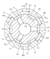
図4及び図5は、油圧制御弁8の動作説明図である。図示の如く、バルブスプール8b外周の長寸の油溝(給油溝)B,B…の両側には、バルブボディー8aの内周に形成された油溝D1 ,D2 (各3本)が、前述の如く絞り面積を変える絞り部を介して連通し、また各油溝D1 ,D2 夫々の他側には、バルブスプール8b外周の短寸の油溝(排油溝)A,A…が、同様の絞り部を介して連通している。給油溝B,Bへの給油のための導油孔86は、全周に亘って周設された環状溝Cと連通しておればよく、例えば、図示の如く、給油溝B,B…の周方向位置に拘らず周方向の適宜位置に一か所設ければよい。一方、排油溝A,A…からの排油のための排油孔87,87…は、夫々の該当位置に設けてある。
【0040】
一方、バルブボディー8aの内周の各3本の油溝D1 ,D2 は、夫々の該当位置にてバルブボディー8aを貫通する各3つの送油孔88,89により、バルブボディー8a外周の残りの2本の環状溝83,84に夫々連通させてある。これらの環状溝83,84は、前述の如く、操舵補助用のパワーシリンダに設定された2か所の送油先、即ち、下側の油室Sb 及び上側の油室Sa に夫々連通しており、前記油溝D1 ,D2 は、油室Sa ,Sb への油圧送給のための送油溝となる。
【0041】
例えば、油溝D1 に対応する送油孔88を環状溝84に、油溝D2 に対応する送油孔89を環状溝83に夫々連通させた場合、図4に示す如く、油溝D1 が上側の油室Sa への送油溝となり、また油溝D2 が下側の油室Sb への送油溝となる。この状態においてバルブボディー8aに対するバルブスプール8bとの相対角変位が、図中に矢符にて示す如く時計回りに生じた場合、給油溝Bの両側の絞り部の絞り面積は、送油溝D1 側が開き、送油溝D2 側が閉じるように変化し、排油溝Aの両側の絞り部の絞り面積は、逆に、送油溝D2 側が開き、送油溝D1 側が閉じるように変化する。
【0042】
従って、給油溝Bへの供給油圧は、送油溝D1 を経て油室Sa に送給され、パワーシリンダのピストン6は、下向き、即ち、油圧制御弁8から遠ざかる向きに押圧され、同方向の操舵補助力が得られる。このとき、他方の油室Sb からの戻り油は、前記導油路33を経て環状溝83に還流し、送油孔89を経て送油溝D2 に還流して、該送油溝D2 の他側に相隣する排油溝Aに導入され、前述した経路を辿って排出される。
【0043】
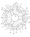
図5は、図4に示す状態からバルブボディー8aを、該バルブボディー8a内周の相隣する送油溝D1 ,D2 間の中心角度(60°)だけ回転させて組み替えた状態を示している。このとき、油溝B及び油溝Aの両側における送油溝D1 ,D2 の相隣関係は、図4に示す相隣関係と逆となる。一方、バルブボディー8aの回転に伴って、該バルブボディー8aに形成された導油孔86、及び送油孔88,89の周方向位置もバルブスプール8bに対して相対的に変化するが、導油孔86を経た油圧の供給は、前記環状溝Cに対してなされており、該環状溝Cに連通する油溝B,B…は、組み替え前と同様に油圧が供給される送油溝となり、また、送油溝D1 ,D2 と油室Sa ,Sb との対応関係は、環状溝83,84と送油孔88,89との連通関係が不変であることから変化しない。
【0044】
この状態において、図4におけると同様に、バルブボディー8aに対するバルブスプール8bとの相対角変位が、図中に矢符にて示す如く時計回りに生じた場合、給油溝Bの両側の絞り部の絞り面積は、送油溝D2 側が開き、送油溝D1 側が閉じるように変化し、排油溝Aの両側の絞り部の絞り面積は、逆に、送油溝D1 側が開き、送油溝D2 側が閉じるように変化する。
【0045】
従って、給油溝Bへの供給油圧は、送油溝D2 及び導油路33を経て油室Sb に送給され、パワーシリンダのピストン6は、上向き、即ち、油圧制御弁8に近付く向きに押圧され、図4におけるそれと逆方向の操舵補助力が得られる。このとき、他方の油室Sa からの戻り油は、玉軸受32の内部を経て環状溝84に還流し、送油孔88を経て送油溝D1 に還流して、該送油溝D1 の他側に相隣する排油溝Aに導入され、前述した経路を辿って排出される。
【0046】
このように油圧制御弁8においては、バルブボディー8aとバルブスプール8bとの簡単な組み替え操作により内部における連通構成を変更し、油溝D1 ,D2 と送油先となる油室Sa ,Sb との対応関係を逆転することができ、右ハンドル車と左ハンドル車の双方に共通して使用することができる。この組み替えは、バルブボディー8aの下縁部に、前記ダウエルピン41との係合のための係合溝を、相隣する送油溝D1 ,D2 間の前記中心角度(60°)分だけ周方向にずらせて2か所設けることにより、容易にしかも確実に達成される。
【0047】
なお、本実施例においては、バルブスプール8bの外周の油溝B,B…を、バルブスプール8b外周の環状溝Cにより連通して給油溝となした構成について述べたが、バルブボディー8a内周の油溝をバルブボディー8a内周の環状溝により連通して給油溝となす構成もまた可能であり、更には、バルブボディー8a(又はバルブスプール8b)側の油溝を、他側、即ち、バルブスプール8b(又はバルブボディー8a)側の環状溝により連通して給油溝となすことも可能である。
【0048】
また本実施例においては、バルブボディー8a及びバルブスプール8bの嵌合周面に各6つの油溝を並設してなる6等配弁について説明したが、これよりも油溝の並設数が少ない又は多い場合においても本発明の適用は可能であり、同様の効果が得られることは言うまでもない。
【0049】
また本実施例においては、ボールねじ式の動力舵取装置への適用例について説明したが、本発明の適用は、ラック・ピニオン式等の他の形式の動力舵取装置にも適用可能であり、更には、油圧の送給先を逆転することが必要となる他の用途にも適用可能である。
【0050】
【発明の効果】
以上詳述した如く本発明に係る油圧制御弁においては、油圧源からの供給油圧をバルブボディーとバルブスプールとの嵌合周面に周設された環状溝に導入し、この環状溝に夫々連通する給油溝に供給し、該給油溝の両側の絞り部における絞り面積の変化に応じて夫々の側の送油溝に振り分けるから、給油溝としての機能を損なうことなくバルブボディーとバルブスプールとの組み付け位置をずらせ、両側の送油溝と送油先との対応関係を逆転させることができ、例えば、動力舵取装置用の油圧制御弁として使用した場合に、右ハンドル車と左ハンドル車とに対する共用が可能となる等、本発明は優れた効果を奏する。
【図面の簡単な説明】
【図1】本発明に係る油圧制御弁を備える動力舵取装置の要部の構成を示す縦断面図である。
【図2】本発明に係る油圧制御弁の構成位置近傍の拡大図である。
【図3】バルブスプールの外周面における油溝の形成態様を示す斜視図である。
【図4】本発明に係る油圧制御弁の動作説明図である。
【図5】本発明に係る油圧制御弁の動作説明図である。
【図6】ラック・ピニオン式の動力舵取装置の構成を示す模式図である。
【図7】ボールねじ式の動力舵取装置の構成を示す模式図である。
【符号の説明】
1 舵輪
2 入力軸
3 シリンダ室
4 ボールねじ軸
6 ピストン
8 油圧制御弁
8a バルブボディー
8b バルブスプール
86 導油孔
87 排油孔
88 送油孔
89 送油孔
A 油溝(排油溝)
B 油溝(給油溝)
C 環状溝
D1 送油溝
D2 送油溝
Sa 油室
Sb 油室[0001]
[Industrial applications]
The present invention relates to a hydraulic control valve that controls supply and discharge of a hydraulic pressure according to a relative angular displacement between a valve body and a valve spool, and more particularly, to a hydraulic power steering device mounted on an automobile, a hydraulic actuator for steering assistance. The present invention relates to a hydraulic control valve used to control a hydraulic pressure supplied to a vehicle in accordance with a steering operation.
[0002]
[Prior art]
2. Description of the Related Art A hydraulic power steering device assists steering by the force generated by a hydraulic actuator such as a double-acting hydraulic cylinder (power cylinder) disposed in a steering mechanism of an automobile, and is required for operating a steering wheel (steering wheel). The purpose is to reduce the burden on the driver and obtain a comfortable steering feeling.
[0003]
The hydraulic actuator for assisting steering is provided with two oil supply destinations for assisting steering in both left and right directions, such as an oil supply port connected to both oil chambers of the power cylinder. The device controls the direction and magnitude of the steering torque applied to the steering wheel between these oil supply destinations, a hydraulic pump (oil pressure source) driven by the engine, and an oil tank (oil discharge destination) that stores hydraulic oil. And a hydraulic control valve for controlling the supply and discharge of the hydraulic pressure according to.
[0004]
As this type of hydraulic control valve, a rotary hydraulic control valve that directly uses the rotation of a steering wheel is widely used. That is, the input shaft connected to the steering wheel and the output shaft connected to the steering mechanism are coaxially connected via a small-diameter torsion bar, and inside the cylindrical valve body engaged with one connection end, A valve spool formed integrally with the other connecting end is fitted coaxially and relatively rotatably.
[0005]
A plurality of oil grooves extending in the axial direction are arranged in parallel in the circumferential direction on the fitting peripheral surface of both, that is, on the inner peripheral surface of the valve body and the outer peripheral surface of the valve spool, These oil grooves are staggered in the circumferential direction on the fitting circumference, and form a plurality of throttle portions that change the throttle area according to the relative angular displacement between adjacent oil grooves. Of the plurality of oil grooves on the valve body or valve spool) side, every other half is an oil supply groove to which the operating oil pressure is supplied from the hydraulic pump, and the other half is an oil discharge destination oil It is an oil drain groove connected to the tank. Further, the oil groove on the other side (valve spool or valve body) between the oil supply groove and the oil discharge groove is alternately communicated with the two oil supply destinations so as to supply oil to these oil supply destinations. Of the oil supply groove.
[0006]
FIG. 6 is a schematic diagram illustrating a configuration of a rack and pinion type power steering device. The rack-and-pinion type steering mechanism has a
[0007]
In such a rack-and-pinion type steering mechanism, a power cylinder S for assisting steering is formed in the middle of the
[0008]
On the other hand, a hydraulic control valve V for controlling the oil pressure supplied to the power cylinder S is provided with an
[0009]
The cylinder port V of the hydraulic control valve V 1 , V 2 And the corresponding oil feed groove are communicated with each other by respective oil feed holes penetrating the peripheral wall of the cylindrical valve body at a corresponding circumferential position, and the pump port V 3 The oil supply groove and the oil supply groove are also communicated with each other by respective oil guide holes that pass through the valve body. Furthermore, tank port V 4 The communication between the oil drain groove and the oil drain groove is performed by using a hollow portion formed in the shaft center portion of the valve spool for inserting the torsion bar, and the return oil received in the oil feed groove is moved to the corresponding position. In the oil collecting hole passing through the valve spool, the oil is collected in the hollow portion. Further, the oil collecting hole is formed through the corresponding position of the valve spool and collected in an oil drain chamber provided on one side of the valve body. The tank port V opening at 4 It is configured to be discharged through.
[0010]
Thus, when a steering torque is applied to the
[0011]
[Problems to be solved by the invention]
In the conventional power steering device configured as described above, the cylinder port V 1 And V 2 Is determined by the internal configuration of the hydraulic control valve V, specifically, the pump port V 3 A pair of oil supply grooves on both sides of an oil supply groove communicating with the cylinder port V 1 And V 2 It depends on the communication mode. In the figure, the cylinder port V 1 (At the lower position), and the oil is supplied from the oil supply pipe P. 1 And oil supply port S 1 As a result, the power cylinder S pushes the
[0012]
However, as shown in FIG. 6A, the above configuration is for an automobile having the
[0013]
Therefore, in such a left-hand drive vehicle, the same configuration as that of the right-hand drive vehicle, that is, the cylinder port V located at the lower position according to the leftward operation of the
[0014]
Therefore, the oil feed pipe P, which is performed at the stage of assembling into a vehicle, 1 , P 2 It is necessary to prepare two types of hydraulic control valves V having different internal communication configurations for the left-hand drive vehicle and the right-hand drive vehicle, respectively. When the control valve V is used for both left and right-hand drive vehicles, for example, there is a problem that it is necessary to take a countermeasure to prevent a difference in connection, such as attaching a tag indicating a connection relationship in the case of left- and right-hand drive vehicles.
[0015]
Such a problem similarly occurs in other types of power steering devices. FIGS. 7A and 7B are schematic diagrams showing the configuration of a ball screw type power steering device. FIG. 7A shows the configuration of a right-hand drive vehicle, and FIG. 7B shows the configuration of a left-hand drive vehicle. I have.
[0016]
In the ball screw type steering mechanism, the
[0017]
The power assisting power cylinder S is configured such that the inside of the
[0018]
Now, in the power steering apparatus of the ball screw type configured as described above, the manner of connection between the
[0019]
Thus, for example, the swing of the
[0020]
Further, in the ball screw type power steering apparatus, as described above, one or both of the oil supply pipes for communication between both oil chambers of the power cylinder S and each of the pair of oil supply grooves of the hydraulic control valve V are provided. In many cases, the above-mentioned problem cannot be solved by changing the connection of the oil supply pipe, and two types of hydraulic control valves V having different communication configurations are prepared for a right-hand drive vehicle and a left-hand drive vehicle. There is a need.
[0021]
The present invention has been made in view of such circumstances, and by a slight rearrangement operation in an assembling stage, it is possible to change the internal communication configuration, reverse the oil supply destination, and use the power steering device. In this case, it is an object to provide a hydraulic control valve that can be applied to both a right-hand drive vehicle and a left-hand drive vehicle.
[0022]
[Means for Solving the Problems]
The hydraulic control valve according to the present invention is configured such that a valve spool is fitted to the inside of a cylindrical valve body so as to be capable of relative angular displacement on the same axis, and a plurality of oil grooves arranged on the fitting circumference of the two are circumferentially arranged. A plurality of oil grooves on one side are alternately communicated with two oil supply destinations, and a plurality of oil grooves on the other side are connected to a hydraulic power source and an oil discharge destination. As an alternately connected oil supply groove and oil discharge groove, the pressure oil supplied to the oil supply groove is distributed on both sides of the oil supply groove in accordance with the change in the throttle area caused by the relative angular displacement, and the oil is supplied to one side. A hydraulic control valve for supplying oil to one of the oil supply destinations via an adjacent oil supply groove, an annular groove provided around the fitting peripheral surface and communicating each of the oil supply grooves with each other; An oil guide hole that penetrates the peripheral wall and introduces a supply oil pressure from the oil pressure source into the annular groove. And butterflies.
[0023]
[Action]
In the present invention, the supply oil pressure from the oil pressure source is introduced into an annular groove provided around the fitting peripheral surface with the valve spool through an oil guide hole penetrating through the valve body, and is supplied to an oil supply groove communicating with the annular groove. The oil is supplied and distributed to the oil supply groove on each side in accordance with a change in the throttle area in the throttle portion on both sides of the oil supply groove, and the oil supply destination corresponding to each oil supply hole through each oil supply hole penetrating through the valve body. To be sent to When reversing the correspondence between the direction of the relative angular displacement and the oil supply destination, the valve body and the valve spool are assembled by shifting the relative position in the circumferential direction by the center angle between adjacent oil supply grooves, The oil feed hole corresponding to one oil feed groove is made to correspond to the other oil feed groove. At this time, the supply position of the oil pressure by the oil guide hole also changes, but the oil guide hole communicates with the annular groove continuous in the circumferential direction, and the oil supply groove communicates with the annular groove and the oil supply groove on both sides. Only the correspondence with the communicating oil destination is reversed.
[0024]
【Example】
Hereinafter, the present invention will be described in detail with reference to the drawings showing the embodiments. FIG. 1 is a longitudinal sectional view showing a main part of a ball screw type power steering apparatus provided with a hydraulic control valve according to the present invention, and FIG. 2 is an enlarged view near a configuration position of the hydraulic control valve.
[0025]
In the figure,
[0026]
A
[0027]
A
[0028]
On the inner periphery of the
[0029]
Thus, when the
[0030]
The upper end of the
[0031]
As described above, the upper end of the
[0032]
The
[0033]
A plurality of oil grooves are formed on the fitting peripheral surface of the
[0034]
The short oil grooves A, A ... and the long oil grooves B, B ... are formed so that their respective ends are aligned, and the other ends of the long oil grooves B, B ... Are extended out of the formation area of the oil grooves A, A... And communicate with an annular groove C provided on the outer peripheral surface of the
[0035]
The
[0036]
An annular groove 83 at the center of the outer periphery of the
[0037]
On the other hand, the annular groove 82 is substantially aligned with the formation position of the annular groove C on the outer periphery of the
[0038]
The other three oil grooves A, A,... On the outer periphery of the
[0039]
4 and 5 are explanatory diagrams of the operation of the
[0040]
On the other hand, each of the three oil grooves D on the inner circumference of the
[0041]
For example, oil groove D 1 The
[0042]
Therefore, the oil pressure supplied to the oil supply groove B is equal to the oil supply groove D 1 Through oil chamber S a And the
[0043]
FIG. 5 shows a state in which the
[0044]
In this state, when the relative angular displacement of the
[0045]
Therefore, the oil pressure supplied to the oil supply groove B is equal to the oil supply groove D 2 And the oil chamber S via the
[0046]
As described above, in the
[0047]
In this embodiment, the oil grooves B on the outer periphery of the
[0048]
Further, in the present embodiment, a description has been given of a six-equal-distribution valve in which six oil grooves are arranged in parallel on the fitting peripheral surface of the
[0049]
Further, in this embodiment, an example of application to a ball screw type power steering device has been described, but the application of the present invention is also applicable to other types of power steering device such as a rack and pinion type. Further, the present invention can be applied to other applications that require reversing the hydraulic pressure supply destination.
[0050]
【The invention's effect】
As described in detail above, in the hydraulic control valve according to the present invention, the hydraulic pressure supplied from the hydraulic pressure source is introduced into the annular grooves provided around the fitting peripheral surface of the valve body and the valve spool, and communicates with the respective annular grooves. The oil is supplied to the oil supply groove, and the oil is distributed to the oil supply groove on each side in accordance with a change in the throttle area in the throttle portion on both sides of the oil supply groove. Therefore, the valve body and the valve spool can be connected without damaging the function as the oil supply groove. The assembling position can be shifted, and the correspondence between the oil supply grooves on both sides and the oil supply destination can be reversed.For example, when used as a hydraulic control valve for a power steering device, a right-hand drive vehicle and a left-hand drive vehicle can be used. The present invention has an excellent effect, for example, it is possible to share the same.
[Brief description of the drawings]
FIG. 1 is a longitudinal sectional view showing a configuration of a main part of a power steering device including a hydraulic control valve according to the present invention.
FIG. 2 is an enlarged view near a configuration position of a hydraulic control valve according to the present invention.
FIG. 3 is a perspective view showing a mode of forming an oil groove on an outer peripheral surface of a valve spool.
FIG. 4 is a diagram illustrating the operation of the hydraulic control valve according to the present invention.
FIG. 5 is a diagram illustrating the operation of the hydraulic control valve according to the present invention.
FIG. 6 is a schematic diagram showing a configuration of a rack and pinion type power steering device.
FIG. 7 is a schematic diagram showing a configuration of a ball screw type power steering device.
[Explanation of symbols]
1 Steering wheel
2 Input shaft
3 Cylinder chamber
4 Ball screw shaft
6 piston
8 Hydraulic control valve
8a Valve body
8b Valve spool
86 Oil guide hole
87 Oil drain hole
88 Oil feed hole
89 Oil feed hole
A Oil groove (oil drain groove)
B Oil groove (oil supply groove)
C annular groove
D 1 Oil feed groove
D 2 Oil feed groove
S a Oil chamber
S b Oil chamber
Claims (1)
Priority Applications (1)
| Application Number | Priority Date | Filing Date | Title |
|---|---|---|---|
| JP14645195A JP3557487B2 (en) | 1995-06-13 | 1995-06-13 | Hydraulic control valve |
Applications Claiming Priority (1)
| Application Number | Priority Date | Filing Date | Title |
|---|---|---|---|
| JP14645195A JP3557487B2 (en) | 1995-06-13 | 1995-06-13 | Hydraulic control valve |
Publications (2)
| Publication Number | Publication Date |
|---|---|
| JPH08337178A JPH08337178A (en) | 1996-12-24 |
| JP3557487B2 true JP3557487B2 (en) | 2004-08-25 |
Family
ID=15407944
Family Applications (1)
| Application Number | Title | Priority Date | Filing Date |
|---|---|---|---|
| JP14645195A Expired - Fee Related JP3557487B2 (en) | 1995-06-13 | 1995-06-13 | Hydraulic control valve |
Country Status (1)
| Country | Link |
|---|---|
| JP (1) | JP3557487B2 (en) |
Families Citing this family (1)
| Publication number | Priority date | Publication date | Assignee | Title |
|---|---|---|---|---|
| CN111332361B (en) * | 2020-04-18 | 2024-06-18 | 沙市久隆汽车动力转向器有限公司 | Integral double-loop steering gear assembly suitable for military off-road vehicle |
-
1995
- 1995-06-13 JP JP14645195A patent/JP3557487B2/en not_active Expired - Fee Related
Also Published As
| Publication number | Publication date |
|---|---|
| JPH08337178A (en) | 1996-12-24 |
Similar Documents
| Publication | Publication Date | Title |
|---|---|---|
| JP2802726B2 (en) | Fluid type, especially hydraulic servo device | |
| EP1149755A2 (en) | Hydraulic power steering apparatus for vehicle | |
| US5156228A (en) | Front wheel steering apparatus | |
| JPH082757B2 (en) | Power steering device | |
| JP2006306239A (en) | Power steering device | |
| JP3557487B2 (en) | Hydraulic control valve | |
| JPH028942B2 (en) | ||
| US20090000855A1 (en) | Power steering device | |
| US2887896A (en) | Power assisted steering mechanism | |
| US4781261A (en) | Four-wheel steering system for automotive vehicles | |
| JPH02212271A (en) | Steering gear ratio changing device | |
| JP4055001B2 (en) | Reduction ratio variable power steering system | |
| JP2004284411A (en) | Reduction gear ratio variable type power steering device | |
| JP2002029430A (en) | Steering system for vehicle | |
| JP2791259B2 (en) | Hydraulic steering system | |
| JP2978338B2 (en) | Steering gear | |
| US4060146A (en) | Power steering mechanism | |
| JP3952694B2 (en) | Variable throttle valve and power steering device | |
| JP2000247247A (en) | Power steering | |
| JPS62155169A (en) | Power steering device | |
| JP2007253653A (en) | Power steering device | |
| JP2580735B2 (en) | Rear wheel steering control device for front and rear wheel steering vehicles | |
| JP4561638B2 (en) | Hydraulic power steering device | |
| JP2536658B2 (en) | 4-wheel steering system for automobiles | |
| JP2000255439A (en) | Hydraulic power steering system |
Legal Events
| Date | Code | Title | Description |
|---|---|---|---|
| A977 | Report on retrieval |
Effective date: 20040223 Free format text: JAPANESE INTERMEDIATE CODE: A971007 |
|
| TRDD | Decision of grant or rejection written | ||
| A01 | Written decision to grant a patent or to grant a registration (utility model) |
Effective date: 20040427 Free format text: JAPANESE INTERMEDIATE CODE: A01 |
|
| A61 | First payment of annual fees (during grant procedure) |
Effective date: 20040427 Free format text: JAPANESE INTERMEDIATE CODE: A61 |
|
| R150 | Certificate of patent (=grant) or registration of utility model |
Free format text: JAPANESE INTERMEDIATE CODE: R150 |
|
| S533 | Written request for registration of change of name |
Free format text: JAPANESE INTERMEDIATE CODE: R313533 |
|
| R350 | Written notification of registration of transfer |
Free format text: JAPANESE INTERMEDIATE CODE: R350 |
|
| FPAY | Renewal fee payment (prs date is renewal date of database) |
Free format text: PAYMENT UNTIL: 20080528 Year of fee payment: 4 |
|
| FPAY | Renewal fee payment (prs date is renewal date of database) |
Free format text: PAYMENT UNTIL: 20090528 Year of fee payment: 5 |
|
| LAPS | Cancellation because of no payment of annual fees |