JP2009006169A - Bathroom module - Google Patents

Bathroom module Download PDF

Info

Publication number
JP2009006169A
JP2009006169A JP2008230940A JP2008230940A JP2009006169A JP 2009006169 A JP2009006169 A JP 2009006169A JP 2008230940 A JP2008230940 A JP 2008230940A JP 2008230940 A JP2008230940 A JP 2008230940A JP 2009006169 A JP2009006169 A JP 2009006169A
Authority
JP
Japan
Prior art keywords
bathtub
apron
bath
waterproof pan
water
Prior art date
Legal status (The legal status is an assumption and is not a legal conclusion. Google has not performed a legal analysis and makes no representation as to the accuracy of the status listed.)
Pending
Application number
JP2008230940A
Other languages
Japanese (ja)
Inventor
Yoshikazu Go
郷  芳和
Kenichi Katayama
健一 片山
Current Assignee (The listed assignees may be inaccurate. Google has not performed a legal analysis and makes no representation or warranty as to the accuracy of the list.)
Toto Ltd
Original Assignee
Toto Ltd
Priority date (The priority date is an assumption and is not a legal conclusion. Google has not performed a legal analysis and makes no representation as to the accuracy of the date listed.)
Filing date
Publication date
Application filed by Toto Ltd filed Critical Toto Ltd
Priority to JP2008230940A priority Critical patent/JP2009006169A/en
Publication of JP2009006169A publication Critical patent/JP2009006169A/en
Pending legal-status Critical Current

Links

Images

Abstract

<P>PROBLEM TO BE SOLVED: To provide a bathroom module, simply fitting a bathtub apron while pressure is applied to a water-tight packing by utilizing the pressing force of a spring member when the bathtub apron is blocked in an opening part formed between a rim part and a bank part. <P>SOLUTION: A rim part of a bathtub has a groove part opened downward along the longitudinal direction, and the bathtub apron has a water-tight member provided on the upper end face of the bathtub apron to be continuous along the longitudinal direction. The upper end part of the bath apron is fitted to the groove part from below, and the bathtub apron is fitted so that the upper end face of the bathtub apron abuts against the groove part through the water-tight member. The bathroom module includes the spring member for applying the upward push-up force from the lower end face side of the bathtub apron to the bathtub apron. <P>COPYRIGHT: (C)2009,JPO&INPIT

Description

本発明は、一般家庭などの浴室として用いられるユニットバス( 「浴室ユニット」とも呼ばれる)に関し、とくに、浴槽、洗い場用防水パン、及びバスエプロンをそれぞれ別体として現場に搬入し、それらのコンポーネントを現場にて一体に組み付けるタイプのユニットバスに関する。   The present invention relates to a unit bath (also referred to as a “bathroom unit”) used as a bathroom in general homes, and in particular, a bathtub, a waterproof pan for a washing place, and a bath apron are carried separately to the site, and their components are installed. It relates to a unit bus that can be assembled on site.

一般家庭で使用されるユニットバスには種々のタイプのものがあり、浴槽と洗い場とが互いに隣接して設置されるタイプのものが主流となっている。   There are various types of unit baths used in general households, and the type of bath in which a bathtub and a washing place are installed adjacent to each other is the mainstream.

このユニットバスには、( I ) : 浴槽と洗い場とを最初から一体に成形し、その一体のまま現場に搬入して施工するタイプのもの、( I I) : 浴槽とバスエプロン付きの洗い場用防水パンとを別体として成形し、施工時に双方を一体に組み付けるタイプのもの、更には、( I I I) : 浴槽、洗い場用防水パン、バスエプロン、及びバスエプロン用の枠体などの主要はコンポーネントをそれぞれ別体として成形して現場に搬入し、現場にて一体に組み付ける分割タイプのものなどがある。   In this unit bath, (I): Bathtub and washing place are molded from the beginning, and the unit is transported to the site as it is, (II): Waterproof for washing place with bathtub and bath apron Bread is molded as a separate body, and both are assembled together at the time of construction. Furthermore, (III): main components such as bathtubs, waterproof pans for washing places, bath apron, and frame for bath apron There are divided types that are molded as separate bodies, carried to the site, and assembled together at the site.

各タイプのユニットバスそれぞれに長所はあるが、現場への搬入性、現場での施工や保守の容易性、更にはユーザの高級感に対する満足度の点から、上述した( I I I) の分割タイプのユニットバスに対する要求は依然として高いものがある。   Each type of unit bus has its advantages, but from the point of view of portability, ease of construction and maintenance on site, and satisfaction with the user's sense of quality, the division type (III) mentioned above The demand for unit buses is still high.

上述した( I I I) の分割タイプのユニットバスの一例として、特許文献1 に記載のユニットバス( 同文献の発明の名称は「洗い場付きユニットバス」) の構造が知られている。このユニットバスは、浴槽、洗い場用防水パン、矩形枠状の立装連結フレーム、及び浴槽遮蔽板部( 開口部用閉蓋、エプロン) を分割した複数のコンポーネントとして備える。このユニットバスの組み付け時には、立装連結フレームを用いて浴槽のフランジ部の一辺と防水パンの土手部の一辺とをビスやボルトで相互に連結する。これにより、浴槽と洗い場用防水パンとが連結に結合されるとともに、立装結合フレームで画成されて作業用開口部が形成される。この作業用開口部には浴槽遮蔽板部が着脱自在に取り付けられる。この作業用開口部を介して施工作業や保守作業を能率良く行なうことができる。
特開2 0 0 3 − 1 1 1 6 8 7 号公報
As an example of the division type unit bus (III) described above, the structure of a unit bus described in Patent Document 1 (the name of the invention of the same document is “unit bus with a washing place”) is known. This unit bath is provided with a plurality of components obtained by dividing a bathtub, a waterproof pan for a washing place, a rectangular frame-like standing connection frame, and a bathtub shielding plate (opening lid, apron). When this unit bath is assembled, one side of the flange portion of the bathtub and one side of the bank portion of the waterproof pan are connected to each other with screws or bolts using a standing connection frame. Accordingly, the bathtub and the waterproof pan for the washing place are coupled to each other, and the working opening is formed by the standing coupling frame. A bathtub shielding plate is detachably attached to the working opening. Construction work and maintenance work can be efficiently performed through this work opening.
Japanese Patent Application Laid-Open No. 2 0 03-1 1 1 6 8 7

しかしながら、リム部と土手部の間に形成される開口部は大きく形成されるため、通常の水密パッキンなどを配置させるだけでは十分に水密性を確保できない場合がある。また、特許文献1に代表される浴室ユニットでは、建築構造物(建築土台、床面など)の上に高さ調整可能な支持架台を直接配置し、この支持架台の上に浴槽を設置する必要がある。   However, since the opening formed between the rim portion and the bank portion is formed to be large, there may be cases where sufficient watertightness cannot be ensured only by arranging a normal watertight packing or the like. Moreover, in the bathroom unit represented by patent document 1, it is necessary to arrange | position the support stand which can adjust height directly on a building structure (building foundation, a floor surface, etc.), and to install a bathtub on this support stand There is.

本発明の態様は、かかる課題の認識に基いてなされたものであり、リム部と土手部の間に形成される開口部にバスエプロンを閉塞する際に、水密パッキンにバネ部材の押圧力を利用して圧力を加えつつ、且つ簡単にバスエプロンの取り付けることができるユニットバスを提供する。   The aspect of the present invention has been made based on recognition of such a problem, and when the bath apron is closed in the opening formed between the rim portion and the bank portion, the pressing force of the spring member is applied to the watertight packing. Provided is a unit bus in which a bus apron can be easily attached while applying pressure using it.

本発明の一態様によれば、上端縁にリム部が形成された浴槽と、前記浴槽の一側面に隣接して配置され且つ土手部が形成された洗い場用防水パンと、前記浴槽のリム部、及び前記防水パンの土手部の間を閉塞する着脱自在なバスエプロンと、を備え、前記浴槽のリム部は、前記長手方向に沿って下向きに開口させた溝部を有し、前記バスエプロンは、当該バスエプロンの上端面に前記長手方向に沿って連続するように設けられた水密部材を有し、前記バスエプロンの上端部を前記溝部にその下側から嵌め込み、当該バスエプロンの上端面を前記水密部材を介して当該溝部に当接させるように当該バスエプロンを取り付けるようにし、前記バスエプロンの下端面側から当該バスエプロンに上向きの押し上げ力を加えるバネ部材を備えたことを特徴とするユニットバスが提供される。   According to one aspect of the present invention, a bathtub having a rim portion formed at an upper edge, a waterproof pan for a washing place that is disposed adjacent to one side surface of the bathtub and has a bank portion, and the rim portion of the bathtub And a detachable bath apron that closes between the bank portions of the waterproof pan, the rim portion of the bathtub has a groove portion opened downward along the longitudinal direction, and the bath apron The bath apron has a watertight member provided so as to be continuous along the longitudinal direction, the upper end portion of the bath apron is fitted into the groove portion from below, and the upper end surface of the bus apron is The bus apron is attached so as to be brought into contact with the groove through the watertight member, and a spring member is provided to apply an upward pushing force to the bus apron from the lower end surface side of the bus apron. Unit bus and is provided.

本発明の態様によれば、リム部と土手部の間に形成される開口部にバスエプロンを閉塞する際に、水密パッキンにバネ部材の押圧力を利用して圧力を加えつつ、且つ簡単にバスエプロンの取り付けることができるユニットバスが提供される。   According to the aspect of the present invention, when the bath apron is closed in the opening formed between the rim portion and the bank portion, the pressure is applied to the watertight packing using the pressing force of the spring member, and it can be easily performed. A unit bus to which a bus apron can be attached is provided.

以下、添付図面を参照して、本発明に係るユニットバスの1 つの実施形態を説明する。   Hereinafter, an embodiment of a unit bus according to the present invention will be described with reference to the accompanying drawings.

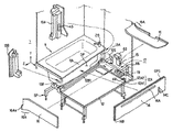
図1 に、この一実施形態に係るユニットバスの全体の外観( 組付け後の外観) を示し、図2 に、このユニットバスの主要コンポーネントを分解した状態( 組付け前) の外観を示す。   FIG. 1 shows the overall appearance of the unit bus according to this embodiment (appearance after assembly), and FIG. 2 shows the appearance of the unit bus in an exploded state (before assembly).

最初に、このユニットバスの主要コンポーネントを中心とする概要を説明する。   First, an outline centering on the main components of this unit bus will be described.

図1 及び図2 に示すように、ユニットバス1 は、その主要コンポーネントの一部として、浴槽1 1 と、この浴槽1 1 に隣接して設置される洗い場用防水パン1 2 ( 以下、防水パン1 2 と呼ぶ) 、この防水パン1 2 と浴槽1 1 とを着脱自在に結合する1 対の結合部材13 A , 1 3 B と、この結合部材1 3 A , 1 3 B 、浴槽1 1 の防水パン側( 一側面側) のリム部1 1 A 1 、及び防水パン1 2 の浴槽側( 一側面側) の土手部1 2 B 1 により画成される矩形状の開口部O P ( 図2 参照) を着脱自在に且つ止水性を保持して閉塞するバスエプロン1 4 とを備える。浴槽1 1 、防水パン1 2 、及び結合部材1 3 A , 1 3 B は共に、一例としてF R P ( 繊維強化プラスチック) で形成される。浴槽1 1 及び防水パン1 2 は、建築構造物( 例えばコンクリート床) 上に置かれた高さ調節用可能な支持架台S P により支持されている。   As shown in FIGS. 1 and 2, the unit bath 1 includes a bathtub 1 1 and a waterproof pan 1 2 for a washing place installed adjacent to the bathtub 1 1 (hereinafter referred to as a waterproof pan) as a part of its main components. 1), a pair of coupling members 13 A and 1 3 B for detachably coupling the waterproof pan 1 2 and the bathtub 1 1, and the coupling members 1 3 A and 1 3 B and the bathtub 1 1 A rectangular opening OP defined by the rim portion 1 1 A 1 on the waterproof pan side (one side surface side) and the bank side portion 1 2 B 1 on the bathtub side (one side surface side) of the waterproof pan 1 2 (FIG. 2) and a bath apron 14 that is detachable and that retains water-stopping properties. The bathtub 1 1, the waterproof pan 1 2, and the coupling members 1 3 A and 1 3 B are all formed of F RP (fiber reinforced plastic) as an example. The bathtub 1 1 and the waterproof pan 12 are supported by a support frame SP that can be adjusted in height and placed on a building structure (for example, a concrete floor).

ここで、説明の便宜のため、浴槽1 1 ( 及び洗い場用防水パン1 2 ) の長手方向をZ 軸とする直交座標系を設定する。この長手方向は、本実施形態にあっては、浴槽1 1 の一側面に位置するリム部1 1 A 1 ( 又は、洗い場用防水パン1 2 の一側面に位置する土手部12 B 1 ) が防止パン1 2 ( 又は浴槽1 1 ) に対向しながら延びる板方向を言う。   Here, for convenience of explanation, an orthogonal coordinate system is set in which the longitudinal direction of the bathtub 1 1 (and the waterproof pan for washing place 1 2) is the Z axis. In this embodiment, the longitudinal direction is such that the rim portion 1 1 A 1 located on one side surface of the bathtub 1 1 (or the bank portion 12 B 1 located on one side surface of the waterproof pan for washing place 1 2). The direction of the plate extending while facing the prevention pan 1 2 (or the bathtub 1 1).

これらの浴槽1 1 、防水パン1 2 、結合部材1 3 A , 1 3 B 、及びバスエプロン1 4 により、この洗い場付き浴槽1 1 は、浴槽の部分、洗い場の部分、及びバスエプロンの部分が予め分離されて提供される「3 分割構造」を特徴とする。すなわち、これらの主要コンポーネント( 浴槽1 1 、防水パン1 2 、結合部材1 3 A , 1 3 B 、及びバスエプロン1 4) は、それぞれ、別体として製造されて現場に搬入され、現場にて一体に組み付けられる。   With these bathtub 1 1, waterproof pan 1 2, coupling members 1 3 A, 1 3 B, and bath apron 1 4, this bathtub 1 1 with washroom has a bathtub portion, a washroom portion, and a bath apron portion. It is characterized by a “three-divided structure” provided separately in advance. That is, these main components (the bathtub 1 1, the waterproof pan 1 2, the coupling members 1 3 A, 1 3 B, and the bath apron 1 4) are each manufactured separately and carried to the site, Can be assembled together.

このため、現場への搬入性がアップして省施工が可能になるほか、サイズの大きい点検口( すなわち開口部O P ) を確保できるため、保守性も高い。また、一体に組付け後の浴槽の外観は浴槽1 及び洗い場床面が互いに別体に見えるため、ユニットバス1 の高級感を醸し出すことができる。   For this reason, in addition to improving the portability to the site and saving work, it is possible to secure a large inspection port (that is, the opening OP), so that maintainability is also high. Moreover, since the bathtub 1 and the wash floor surface can be seen separately from each other, the appearance of the unit bath 1 can be given a high-class feeling.

このユニットバス1 は、さらに別の主要コンポーネントとして、防水パン1 2 のZ 軸方向の一端部にて床面から所定高さの位置にほぼ水平に設置される洗い場カウンタ1 5 と、この洗い場カウンタ1 5 の手前側の位置に立設される化粧板( 蓋板) 1 6 と、この洗い場カウンタ1 5 、化粧板1 6 、及び壁面とに囲まれたスペースを利用して配置される給水配管部1 7 とを備える。このうち、洗い場カウンタ1 5 及び化粧板1 6 は利用者であっても簡単に着脱できるようになっている。   This unit bath 1 includes, as yet another main component, a washing place counter 15 installed almost horizontally at a predetermined height from the floor at one end of the waterproof pan 12 in the Z-axis direction, and this washing place counter. A water supply pipe arranged using a space surrounded by a decorative plate (cover plate) 1 6 standing at a position on the near side of 1 5 and the washing counter 1 5, the decorative plate 1 6, and the wall surface Part 1 7. Among these, the washing counter 1 5 and the decorative plate 1 6 can be easily attached and detached even by a user.

次に、図3 〜 1 6 を参照して、このユニットバス1 の主要コンポーネントの構造をその作用効果と共に詳述する。   Next, with reference to FIGS. 3 to 16, the structure of the main components of the unit bus 1 will be described in detail together with the effects thereof.

( 1 . 浴槽)
図3 及び図4 に示すように、浴槽1 1 は、利用者が身体を伸ばして入浴できるように細長い内容積のバスタブT B を有し、そのバスタブT B の周囲にリム部1 1 A を形成している。リム部1 1 A は、その長手方向( Z 軸方向) に沿って位置し且つ防止パン1 2 に隣接する第1 のリム部1 1 A 1 と、この第1 のリム部1 1 A 1 に連なってバスタブT B の縁を一周する第2 〜 第4 のリム部1 1 A 2 〜 1 1 A 4 とから成る。
(1. Bathtub)
As shown in FIG. 3 and FIG. 4, the bathtub 1 1 has an elongated inner volume bathtub T B so that the user can stretch and bathe, and a rim portion 1 1 A is provided around the bathtub T B. Forming. The rim portion 1 1 A is located along the longitudinal direction (Z-axis direction) and adjacent to the prevention pan 1 2, and the first rim portion 1 1 A 1. It consists of second to fourth rim portions 1 1 A 2 to 1 1 A 4 that continuously go around the edge of the bathtub TB.

このうち、第1 のリム部1 1 A 1 は、図4 に示すように、バスタブT B を形成する壁体が所定高さの位置で所定幅の湾曲部を残すように折れ曲がって一体成形されている。この湾曲部により、下向き( Y 軸方向) に開口する略U 字状の溝部2 1 が形成されている。この溝部2 1 には、その幅方向( X 軸方向) の中心付近の位置に、所定高さで且つ溝部2 の長手方向( Z 軸方向) 全体にわたって延びる長さの仕切り板2 2 が垂下されている。これにより、溝部2 1 がその長手方向に沿って略二分されている。この二分された溝部2 1A , 2 1 B のうち、防水パン側の溝部2 1 A は、後述するようにバスエプロン1 4 を着脱自在に装着するスペースとして使用される。   Among these, the first rim portion 1 1 A 1 is integrally formed by bending so that the wall forming the bathtub T B leaves a curved portion having a predetermined width at a predetermined height, as shown in FIG. ing. The curved portion forms a substantially U-shaped groove 2 1 that opens downward (in the Y-axis direction). A partition plate 2 2 having a predetermined height and a length extending over the entire length direction (Z-axis direction) of the groove portion 2 is suspended from the groove portion 2 1 at a position near the center in the width direction (X-axis direction). ing. Thereby, the groove part 2 1 is substantially bisected along the longitudinal direction. Of the bisected grooves 2 1A and 2 1 B, the groove 2 1 A on the waterproof pan side is used as a space for detachably mounting the bath apron 1 4 as will be described later.

第1 のリム部1 1 A 1 から第2 のリム部1 1 A 2 に至る角部には、例えば図3 に示すように、浴槽水栓2 5 が立設されている。この浴槽水栓2 5 は、その角部( リム部) の裏側で後述する2 本の配管( 給水配管及び給湯配管) に接続されている。   For example, as shown in FIG. 3, a bathtub faucet 2 5 is erected at a corner portion from the first rim portion 1 1 A 1 to the second rim portion 1 1 A 2. The bathtub faucet 25 is connected to two pipes (a water supply pipe and a hot water supply pipe) to be described later on the back side of the corner (rim part).

第2 〜 第4 のリム部1 1 A 2 〜 1 1 A 4 には、詳述しないが、立ち上がり部がそれぞれ形成され、この立ち上がり部に浴室の壁体を嵌め込んで止水処理することで止水性を確保している。   Although not described in detail in the second to fourth rim portions 1 1 A 2 to 1 1 A 4, rising portions are respectively formed, and a wall of a bathroom is fitted into the rising portions to perform a water stop treatment. Ensures waterstop.

( 2 . 防水パン)
一方、防水パン1 2 は、高さ方向( Y 軸方向) において、浴槽1 1 のリム部1 1 A よりも低い位置に設置される。防水パン1 2 は、床面部1 2 A と、その床面部1 2 A の周囲に立ち上がりを一体に形成する土手部1 2 B から成る。床面部1 2 A は、洗い場の中心となる床面本体1 2 A 1 と、長手方向( Z 軸方向) の一端部に床面本体1 2 A 1 から段差によって画成された略矩形状の段差部1 2 A 2 とから成る。床面本体1 2 A 1 は浴槽寄りの1つの角部に向かって緩やかに傾斜しており、その角部に形成された排水口3 1 に導水できるようになっている。段差部1 2 A 2 には、後述する給水配管部1 7 が設置される。
(2. Waterproof pan)
On the other hand, the waterproof pan 1 2 is installed at a position lower than the rim 1 1 A of the bathtub 1 1 in the height direction (Y-axis direction). The waterproof pan 12 includes a floor surface portion 12A and a bank portion 12B that integrally forms a rise around the floor surface portion 12A. The floor surface portion 1 2 A has a substantially rectangular shape defined by a step from the floor surface body 1 2 A 1 which is the center of the washing place and one end portion in the longitudinal direction (Z-axis direction). It consists of level difference part 1 2 A 2. The floor main body 1 2 A 1 is gently inclined toward one corner near the bathtub, and can conduct water to a drain port 3 1 formed at the corner. A water supply pipe portion 1 7 described later is installed in the step portion 1 2 A 2.

この防水パン1 2 の土手部1 2 B は、図2 、3 に示すように、その長手方向( Z 軸方向) に沿って位置し且つ浴槽1 1 に隣接する第1 の土手部1 2 B 1 と、この第1 の土手部12 B 1 に連なって防水パン1 2 の縁を一周する第2 〜 第4 の土手部1 2 B 2 〜 1 2 B 4 とから成る。   As shown in FIGS. 2 and 3, the bank portion 1 2 B of the waterproof pan 1 2 is positioned along the longitudinal direction (Z-axis direction) and adjacent to the bathtub 1 1. 1 and second to fourth bank portions 12 B 2 to 12 B 4 that are connected to the first bank portion 12 B 1 and go around the edge of the waterproof pan 12.

このうち、第1 の土手部1 2 B 1 は、図4 から分かるように、床面本体1 2 A 1 及び段差部1 2 A 2 から横方向( X 軸方向) に延びる幅の狭いレール状床面3 2 A と、このレール状床面3 2 A から上方向( Y 軸方向) に立ち上がる立ち上がり面3 2 B と、この立ち上がり面3 2 B から更に横方向に伸びて立ち上がる形状の立ち上がり部3 2 C とを成る。つまり、この第1 の土手部1 2 B 1 は2 段階で立ち上がる形状になっている。1 段目のレール状床面3 2 A は、後述するようにバスエプロン1 4 を着脱自在に装着するために使用される。   Among these, as can be seen from FIG. 4, the first bank portion 1 2 B 1 has a narrow rail shape extending in the horizontal direction (X-axis direction) from the floor main body 1 2 A 1 and the stepped portion 1 2 A 2. A floor surface 3 2 A, a rising surface 3 2 B that rises upward (Y-axis direction) from the rail-shaped floor surface 3 2 A, and a rising portion that extends further from the rising surface 3 2 B in the lateral direction 3 2 C. That is, the first bank portion 1 2 B 1 has a shape that rises in two stages. The first rail-like floor surface 3 2 A is used for detachably mounting the bus apron 1 4 as will be described later.

このため、最初の立ち上がり面3 2 B には、その内側に、複数個のバネ3 3 を所定高さ位置で長手方向( Z 軸方向) に沿って一定間隔で配置されている。この複数個のバネ3 3は、それぞれ、所定長さ且つ所定幅の鋼材を、側面から見て基部3 3 A から立ち上がる逆V 字状の折り曲げ部を有するように折り曲げて形成され、その折り曲げ部に所望のバネ性を持たせている。各バネ3 3 はその逆V 字状の折り曲げ部を下向きに開口した状態で取り付けられる。これにより、複数個のバネ3 3 が協働して、それらの折り曲げ部の底部でバスエプロン1 4 の底面に形成される略V 字状の凹部を着脱自在に受け入れ且つそのバスエプロン1 4 に上向き( Y 軸方向) 且つ横向き( X 軸方向で浴槽向き) の成分を有する斜め方向に押圧力を加える。   For this reason, on the first rising surface 3 2 B, a plurality of springs 3 3 are arranged at regular intervals along the longitudinal direction (Z-axis direction) at predetermined height positions. Each of the plurality of springs 33 is formed by bending a steel material having a predetermined length and a predetermined width so as to have an inverted V-shaped bent portion that rises from the base portion 3 3 A when viewed from the side surface. Has a desired spring property. Each spring 33 is attached with its inverted V-shaped bent part opened downward. As a result, the plurality of springs 3 3 cooperate to removably receive a substantially V-shaped recess formed on the bottom surface of the bath apron 1 4 at the bottom of the bent portion, and to the bus apron 1 4. A pressing force is applied in an oblique direction having components of upward (Y-axis direction) and lateral direction (X-axis direction toward the bathtub).

上述した第1 の土手部1 2 B 1 のうち、2 段目の立ち上がり部3 2 C は各種の止水パッキンを以ってしても沁み出した水分があるときに、これを蓄えて自然乾燥させるための止水に対するバッファとしての役目を与えている。   Of the first bank portion 1 2 B 1 described above, the second-stage rising portion 3 2 C stores water that has squeezed out even with various water-stopping packings. It serves as a buffer against water stoppage for drying.

さらに、防水パン1 2 の第2 〜 第4 の土手部1 2 B 2 〜 1 2 B 4 にも、詳述しないが、立ち上がり部がそれぞれ形成され( 例えば図4 の第2 の土手部1 2 B 2 を参照) 、この立ち上がり部に浴室の壁体を嵌め込んで止水処理することで止水性が確保される。第3 の土手部1 2 B 3 の所定範囲に及ぶ位置には、浴室出入り用のドアが設置される。   Furthermore, although not described in detail in the second to fourth bank portions 12 B 2 to 12 B 4 of the waterproof pan 12, rising portions are formed respectively (for example, the second bank portion 12 of FIG. 4). B2)), the water-stopping property is ensured by fitting the wall of the bathroom to the rising portion and performing the water-stopping treatment. A door for entering and leaving the bathroom is installed at a position extending over a predetermined range of the third bank portion 1 2 B 3.

なお、防水パン1 2 の段差部1 2 A 2 については、給水配管部1 7 と共に後述する。   The stepped portion 1 2 A 2 of the waterproof pan 1 2 will be described later together with the water supply piping portion 1 7.

( 結合部材)
さらに、1 対の結合部材1 3 A , 1 3 B のうち、第1 の結合部材1 3 A の全体斜視図を図5 に示す。この第1 の結合部材1 3 A は、図5 に示すように、浴室の壁体の一部を支持するための支持体( ポスト部) 3 9 と、略板状で所定厚さ及び所定長さを有する支柱体(ピラー部) 4 1 と、この支柱体4 1 と支柱体3 9 とを相互に剛結する矩形板状の中間部材4 0 とを備える。この中間部材4 0 は、その取り付け状態における下端側の一部が支柱体3 9 より短く形成される一方で、その上端部は支柱体3 9 と同一高さに形成されている。
(Coupling member)
Furthermore, FIG. 5 shows an overall perspective view of the first coupling member 1 3 A among the pair of coupling members 1 3 A and 1 3 B. As shown in FIG. 5, the first coupling member 1 3 A has a support (post part) 3 9 for supporting a part of the wall of the bathroom, a substantially plate shape, a predetermined thickness and a predetermined length. And a columnar intermediate member 4 0 that rigidly connects the column body 4 1 and the column body 3 9 to each other. The intermediate member 4 0 is formed such that a part of the lower end side in the attached state is shorter than the column body 3 9, while its upper end portion is formed at the same height as the column body 3 9.

支柱体4 1 は、略板状の基板部4 1 A と、この基板部の一方の表面S 1 ( 第1 の当接面) の途中から直角( 又は鈍角: 図5 中の角度θ 参照) に立ち上がる面S 2 ( 第2 の当接面) を介して凸状に形成された膨張部4 1 B と、支柱体4 1 の取り付け状態での下端部から突状に延設されたフランジ部4 1 C と、支柱体4 1 の取り付け状態における上端部に凹んで形成された段差部4 1 D とを一体に有する。フランジ部4 1 C ( 及び基板部4 1 A ) の板面方向と膨張部4 1 B の膨張方向( 凸部方向) とは直交するように設定されている。   The column body 4 1 is a right angle from the middle of the substantially plate-like substrate portion 4 1 A and one surface S 1 (first contact surface) of the substrate portion (or obtuse angle: see angle θ in FIG. 5). And a flange portion projectingly extended from a lower end portion of the support body 4 1 in a mounted state, with the inflated portion 4 1 B formed through a surface S 2 (second contact surface) rising on 4 1 C and a stepped portion 4 1 D formed in a recessed manner at the upper end in the attached state of the column body 4 1 are integrally provided. The plate surface direction of the flange portion 4 1 C (and the substrate portion 4 1 A) and the expansion direction (convex portion direction) of the expansion portion 4 1 B are set to be orthogonal to each other.

中間部材4 0 の上端部は、段差部4 1 D の底面の一部を成している。この中間部材4 0の位置には、図6 に示すように、組み付け時に浴室の壁体W L を位置させる。このため、支持体3 9 は、壁体W L の後ろ側に位置し、壁体W L の奥に隠れるので、この壁体W L の取り付けに使用される。   The upper end portion of the intermediate member 4 0 forms a part of the bottom surface of the step portion 4 1 D. As shown in FIG. 6, the wall member W L of the bathroom is positioned at the position of the intermediate member 40 during assembly. For this reason, since the support body 3 9 is located behind the wall body WL and is hidden behind the wall body WL, it is used for mounting the wall body WL.

支持体3 9 は、略矩形状の板状部材でなるが、その取り付け状態における下端部にその板面方向に3 角形状に広がる広がり部3 9 A を有し、その上端部にその板面方向に突き出た突き出し部3 9 B を有して一体に形成されている。支持体3 9 の広がり部3 9 A を含む下端面は前記中間部材のそれと同一面をなすように形成される一方で、突き出し部3 9 Bは支柱体4 1 よりも高く形成されている。このため、支持体3 9 の板面方向は、フランジ部4 1 C ( 及び基板部4 1 A ) のそれとも直交している。   The support 3 9 is made of a substantially rectangular plate-like member, and has a widened portion 3 9 A spreading in a triangular shape in the plate surface direction at the lower end portion in the attached state, and the plate surface at the upper end portion. The protruding portion 3 9 B protruding in the direction is integrally formed. The lower end surface including the widened portion 3 9 A of the support 3 9 is formed so as to be flush with that of the intermediate member, while the protruding portion 3 9 B is formed higher than the column body 4 1. For this reason, the plate surface direction of the support 3 9 is orthogonal to that of the flange portion 4 1 C (and the substrate portion 4 1 A).

フランジ部4 1 C の一部には、図5 に示すように、その面が一部凹んだ凹部4 1 C a が形成されている。この凹部4 1 C a をネジにより防水パン1 2 の第1 の土手部1 2 B 1 の壁面に固定することで、第1 の結合部材1 3 A が防水パン1 2 に結合される。   As shown in FIG. 5, a recess 4 1 C a having a partially recessed surface is formed in a part of the flange portion 4 1 C. The first coupling member 1 3 A is coupled to the waterproof pan 1 2 by fixing the concave portion 4 1 C a to the wall surface of the first bank portion 1 2 B 1 of the waterproof pan 1 2 with a screw.

図5 に示すように、この第1 の結合部材1 3 A の支柱体4 1 の底面及び接続部材の底面に掛けて水密部材L B 1 が貼り付けられている。また、支柱体4 1 の段差部4 1 D 及び支持体3 9 の突き出し部3 9 B に掛けて水密部材L B 2 が貼り付けられている。   As shown in FIG. 5, the watertight member L B 1 is attached to the bottom surface of the column body 4 1 of the first coupling member 1 3 A and the bottom surface of the connection member. A watertight member L B 2 is attached to the stepped portion 4 1 D of the support body 4 1 and the protruding portion 3 9 B of the support 3 9.

さらに、この第1 の結合部材1 3 A の軸方向の取り付け状態での上端部には、浴槽1 1への取り付け用の金具4 2 が取り付けられている。   Furthermore, a fitting 4 2 for attachment to the bathtub 11 is attached to the upper end portion of the first coupling member 1 3 A in the axial attachment state.

また、膨張部4 1 B の部分には、その表裏を貫通する貫通孔4 3 が所定高さの位置に形成されている。この貫通孔4 3 は、後述する配管を通過させるためのものである。   Moreover, the through-hole 4 3 which penetrates the front and back is formed in the position of predetermined | prescribed height in the part of expansion | swelling part 4 1B. This through-hole 4 3 is for letting the piping mentioned later pass.

これに対して、防水パン1 2 の第1 の土手部1 2 B 1 の端部には、図5 に示すように、第1 の結合部材1 3 A の支柱体4 1 のL 字状の底部の形状に合わせた切込み部4 4 が形成されている。このとき、第1 の結合部材1 3 A の下端部を、かかる切込み部4 3 に差し込んだときに、図6 に示すように、第1 の土手部1 2 B 1 の立ち上がり部3 2 B の面S 3 と、第1 の結合部材1 3 A の支柱体4 1 の表面S 1 ( 第1 の当接面) とが同一面を形成するように、それらのサイズが設定されている。   On the other hand, as shown in FIG. 5, the end of the first bank portion 1 2 B 1 of the waterproof pan 1 2 has an L-shape of the support body 4 1 of the first coupling member 1 3 A. A cut portion 4 4 is formed in accordance with the shape of the bottom portion. At this time, when the lower end portion of the first coupling member 1 3 A is inserted into the cut portion 4 3, as shown in FIG. 6, the rising portion 3 2 B of the first bank portion 1 2 B 1 The sizes thereof are set so that the surface S 3 and the surface S 1 (first contact surface) of the column body 4 1 of the first coupling member 1 3 A form the same surface.

また、浴槽1 1 の第1 のリム部1 1 A 1 と第2 のリム部1 1 A 2 との間の角部には、浴槽水栓2 5 を取り付け用の金具4 2 で迂回する状態で、第1 の結合部材1 3 A の支柱体41 の上端部が固設される( 図6 参照) 。このとき、第1 のリム部1 1 A 1 に形成された防水パン側の溝部2 1 A の一部を画成する仕切り板2 2 の面S 4 と第1 の結合部材1 3 A の支柱体4 1 の面S 1 とが同一面を形成するようにサイズが設定されている。   In addition, the bathtub faucet 2 5 is bypassed by the mounting bracket 4 2 at the corner between the first rim 1 1 A 1 and the second rim 1 1 A 2 of the bathtub 1 1. Thus, the upper end portion of the support body 41 of the first coupling member 1 3 A is fixed (see FIG. 6). At this time, the surface S 4 of the partition plate 2 2 that defines a part of the groove portion 2 1 A on the waterproof pan formed in the first rim portion 1 1 A 1 and the column of the first coupling member 1 3 A The size is set so that the surface S 1 of the body 4 1 forms the same surface.

第2 の結合部材1 3 B を図8 〜 1 0 を参照して説明する。この第2 の結合部材1 3 B は、図8 に示すように、浴室の壁体の一部を支持するための支持体( ポスト部) 4 9 と、略直方体状で所定厚さ及び所定長さを有する支柱体( ピラー部) 5 1 と、この支柱体5 1 と支柱体4 9 とを相互に剛結する矩形板状の中間部材5 0 とを備える。この中間部材5 0 は、その取り付け状態における下端側及び上端部の高さが支柱体4 9 と同一に形成されている。   The second coupling member 1 3 B will be described with reference to FIGS. 8 to 10. As shown in FIG. 8, the second coupling member 1 3 B has a support body (post part) 4 9 for supporting a part of the wall of the bathroom, a substantially rectangular parallelepiped shape, a predetermined thickness and a predetermined length. And a columnar intermediate member 5 0 that rigidly connects the column body 5 1 and the column body 4 9 to each other. The intermediate member 50 is formed such that the lower end side and the upper end portion thereof in the attached state have the same height as the column body 4 9.

支柱体5 1 は、基部5 1 A と、この基部5 1 A の一方の表面S 5 ( 第1 の当接面) の途中から直角に立ち上がる面S 6 ( 第2 の当接面) を介して凸状に形成された膨張部5 1 Bと、支柱体5 1 の取り付け状態における基部5 1 A の下端部から突状に延設されたフランジ部5 1 C と、支柱体5 1 の取り付け状態における上端部に凹んで形成された段差部5 1D とを一体に有する。なお、面S 6 は表面S 5 から鈍角の角度で立ち上がるようにしてもよい。フランジ部5 1 C ( 及び基部5 1 A ) の突設方向と膨張部5 1 B の膨張方向( 凸部方向) とは直交するように設定されている。   The column body 5 1 is interposed between the base 5 1 A and a surface S 6 (second contact surface) that rises at a right angle from the middle of one surface S 5 (first contact surface) of the base 5 1 A. Of the inflated portion 5 1 B formed in a convex shape, the flange portion 5 1 C projecting from the lower end portion of the base portion 5 1 A in the attached state of the column body 5 1, and the attachment of the column body 5 1 And a step portion 51D formed in a recessed manner at the upper end in the state. Note that the surface S 6 may rise from the surface S 5 at an obtuse angle. The protruding direction of the flange portion 5 1 C (and the base portion 5 1 A) and the expansion direction (convex portion direction) of the expansion portion 5 1 B are set to be orthogonal to each other.

中間部材5 0 の上端部は、段差部5 1 D の底面の一部を成している。この中間部材4 0の位置には、組み付け時に浴室の壁体W L を位置させる。このため、支持体4 9 は、壁体W L の後ろ側に位置し、壁体W L の奥に隠れるので、この壁体W L の取り付けに使用される。   The upper end portion of the intermediate member 5 0 forms a part of the bottom surface of the step portion 5 1 D. At the position of the intermediate member 40, the wall body W L of the bathroom is positioned at the time of assembly. For this reason, since the support body 4 9 is located behind the wall body WL and is hidden behind the wall body WL, it is used for mounting the wall body WL.

支持体4 9 は、略矩形状の板状部材で成るが、その取り付け状態における上端部にその
板面方向に突き出し且つ支柱体5 1 よりも高く突き出した突き出し部3 9 A を有して一体に形成されている。支持体3 9 の板面方向は、フランジ部4 1 C ( 及び基板部4 1 A ) のそれとも直交している。
The support body 4 9 is formed of a substantially rectangular plate-like member, and has an protruding portion 3 9 A protruding in the plate surface direction at the upper end portion in the attached state and protruding higher than the column body 5 1. Is formed. The plate surface direction of the support 3 9 is orthogonal to that of the flange portion 4 1 C (and the substrate portion 4 1 A).

フランジ部5 1 C の一部には、図8 に示すように、その面が一部凹んだ凹部5 1 C a が形成されている。この凹部5 1 C a をネジにより防水パン1 2 の第1 の土手部1 2 B 1 の壁面に固定することで、第2 の結合部材1 3 B が防水パン1 2 に結合される。   As shown in FIG. 8, a concave portion 5 1 C a having a partially recessed surface is formed in a part of the flange portion 5 1 C. The second coupling member 1 3 B is coupled to the waterproof pan 1 2 by fixing the concave portion 5 1 C a to the wall surface of the first bank portion 1 2 B 1 of the waterproof pan 1 2 with a screw.

図8 に示すように、この第2 の結合部材1 3 B の支柱体5 1 の底面及び接続部材5 0 の底面に掛けて水密部材L B 3 が貼り付けられている。また、支柱体5 1 の段差部5 1 D 及び支持体4 9 の突き出し部4 9 A に掛けて水密部材L B 4 が貼り付けられている。   As shown in FIG. 8, the watertight member L B 3 is attached to the bottom surface of the support column 5 1 of the second coupling member 1 3 B and the bottom surface of the connection member 5 0. Further, the watertight member L B 4 is attached to the stepped portion 5 1 D of the support body 5 1 and the protruding portion 4 9 A of the support body 4 9.

さらに、この第2 の結合部材1 3 B の軸方向の取り付け状態での上端部には、浴槽1 1への取り付け用の金具5 2 が取り付けられている。   Furthermore, a fitting 5 2 for attachment to the bathtub 11 is attached to the upper end portion of the second coupling member 1 3 B in the axial attachment state.

これに対して、防水パン1 2 の第1 の土手部1 2 B 1 のもう一方の端部には、図8 に示すように、第2 の結合部材1 3 B の底部の形状に合わせた切込み部5 3 が形成されている。このとき、第2 の結合部材1 3 B の下端部をかかる切込み部4 3 に差し込んだときに、図9 に示すように、第1 の土手部1 2 B 1 の立ち上がり部3 2 B の面S 3 と、第2 の結合部材1 3 B の支柱体5 1 の面S 5 とが同一面を形成するように、それらのサイズが設定されている。   On the other hand, the other end of the first bank portion 1 2 B 1 of the waterproof pan 1 2 is matched with the shape of the bottom portion of the second coupling member 1 3 B as shown in FIG. A cut portion 5 3 is formed. At this time, when the lower end portion of the second coupling member 1 3 B is inserted into the cut portion 4 3, as shown in FIG. 9, the surface of the rising portion 3 2 B of the first bank portion 1 2 B 1 Their sizes are set so that S 3 and the surface S 5 of the column body 5 1 of the second coupling member 1 3 B form the same surface.

また、浴槽1 1 の第1 のリム部1 1 A 1 と第4 のリム部1 1 A 4 との間の角部には、取り付け用の金具5 2 を介して第2 の結合部材1 3 B の上端部が固設される( 図9 参照) 。このとき、第1 のリム部1 1 A 1 に形成された防水パン側の溝部2 1 A の一部を画成する仕切り板2 2 の面S 4 と第2 の結合部材1 3 B の支柱体5 1 の面S 5 とが同一面を形成するように、それらのサイズが設定されている。   In addition, a second coupling member 1 3 is attached to a corner portion between the first rim portion 1 1 A 1 and the fourth rim portion 1 1 A 4 of the bathtub 1 1 via an attachment fitting 5 2. The upper end of B is fixed (see FIG. 9). At this time, the surface S 4 of the partition plate 2 2 that defines a part of the groove 2 1 A on the waterproof pan formed in the first rim 1 1 A 1 and the column of the second coupling member 1 3 B Their sizes are set so that the surface S 5 of the body 5 1 forms the same surface.

( バスエプロン)
バスエプロン1 4 は、所定厚さを有するF R P などの素材で形成された所定厚さで略矩形状の板体である。このバスエプロン1 4 の厚さは、第1 及び第2 の結合部材1 3 A , 13 B の膨張部4 1 B , 5 1 B の高さに略一致させている。
(Bus Apron)
The bath apron 14 is a plate having a predetermined thickness and a substantially rectangular shape formed of a material such as F R P having a predetermined thickness. The thickness of the bath apron 1 4 is made to substantially coincide with the height of the inflating portions 4 1 B and 5 1 B of the first and second coupling members 1 3 A and 13 B.

さらに、バスエプロン1 4 の上端側の所定位置には、図4 に示すように、その長手方向( 取り付け時においてZ 軸方向) に沿って取手部1 4 A が形成されている。これと共に、バスエプロン1 4 の底面には、前述した防水パン1 2 の第1 の土手部1 2 B 1 に設けた複数個のバネ3 3 の逆V 字状面に合った略V 字状の溝1 4 B が形成されている。   Furthermore, as shown in FIG. 4, a handle portion 1 4 A is formed at a predetermined position on the upper end side of the bath apron 1 4 along the longitudinal direction (Z-axis direction at the time of attachment). At the same time, the bottom of the bath apron 1 4 has a substantially V shape that matches the inverted V shape surface of the plurality of springs 3 3 provided on the first bank portion 1 2 B 1 of the waterproof pan 1 2 described above. Grooves 1 4 B are formed.

さらに、このバスエプロン1 4 には、図1 4 ( a ) , ( b ) に概略示すように、その周囲を略2 重に取り巻く水密手段が設けられている。一方の水密手段は、取り付け状態のおける浴槽1 1 側の外表面上1 4 A であって、その板厚方向に直交する4 周の側面の端部近傍の位置に沿って矩形状に完全に一周して取り付けられた、ストリップ状の水密パッキン( ゴムパッキン) G P 1 で成る。もう一方の水密手段は、バスエプロンの板厚方向に直交する4 周の側面のうちの、取り付け状態における上側面及び左右側面の3 側面に沿って取り付けられた、ストリップ状の水密パッキン( ゴムパッキン) G P 2 で成る。これらの水密パッキンG P 1 , G P 2 は、予めバスエプロン1 4 に取り付けられ、バスエプロン1 4の開口部O P への取り付け時には、後述するように、浴槽1 1 及び防水パン1 2 に対して適度な押圧力で押し付けられて水密性能を発揮するようになっている。   Further, the bath apron 1 4 is provided with watertight means that surrounds the periphery of the bath apron 1 4 in an approximately double manner, as schematically shown in FIGS. 14 (a) and (b). One watertight means is a rectangular shape along the position near the end of the four side surfaces orthogonal to the plate thickness direction on the outer surface 14 A on the bathtub 1 1 side in the attached state. It consists of a strip-shaped watertight packing (rubber packing) GP 1 that is attached around the circumference. The other water-tight means is a strip-like water-tight packing (rubber packing) attached along the three side surfaces of the upper and left and right side surfaces in the mounted state of the four side surfaces orthogonal to the thickness direction of the bath apron. ) It consists of GP2. These watertight packings GP 1 and GP 2 are attached in advance to the bath apron 14, and when attached to the opening OP of the bath apron 14, as will be described later, in the bathtub 1 1 and the waterproof pan 1 2. On the other hand, it is pressed with an appropriate pressing force and exhibits watertight performance.

さらに、バスエプロン1 4 の防水パン1 2 側の面には、略L 字状の有底状のロック用溝1 4 C が形成されている。このロック用溝1 4 C には、後述する化粧板1 6 の端部に形成した端部が嵌合可能になっている。このため、ユニットバス1 の組付け時に、バスエプロン1 4 を装着した後、化粧板1 6 の端部がこのロック用溝1 4 C に収まらないときには、バスエプロン1 4 の開口部O P への装着が不完全であることが分かるようになっている。この場合には、バスエプロン1 4 が所定の位置に収まるように装着作業をし直すことになる。   Furthermore, a substantially L-shaped bottomed locking groove 1 4 C is formed on the surface of the bath apron 1 4 on the waterproof pan 1 2 side. An end portion formed at an end portion of a decorative plate 1 6 described later can be fitted into the locking groove 1 4 C. For this reason, when the end of the decorative plate 1 6 does not fit in the locking groove 1 4 C after the bath apron 1 4 is attached when the unit bus 1 is assembled, the opening OP of the bus apron 1 4 is moved to the opening OP. It can be seen that the mounting of is incomplete. In this case, the mounting operation is performed again so that the bus apron 1 4 is in a predetermined position.

なお、このバスエプロン1 4 と防水パン1 2 の第1 の土手部1 2 B 1 のレール状床面32 A との間には、目地材4 8 が置かれる( 図1 6 参照) 。   A joint material 4 8 is placed between the bath apron 14 and the rail-like floor surface 32 A of the first bank portion 1 2 B 1 of the waterproof pan 12 (see FIG. 16).

( 5 . 洗い場カウンタ、化粧板、及び給水配管部)
給水配管部1 7 は、図3 に示すように、防水パン1 2 のZ 軸方向の一端部に一体形成された段差部1 2 A 2 の位置に設けられる。つまり、この給水配管部1 7 は、防止パン1 2の床面の一部を成す段差部1 2 A 2 の所定位置に立設された外部の配管( 給水配管及び給湯配管) に接続する接続部6 1 と、この接続部6 1 に接続された2 本の浴室配管6 2 A ,6 2 B ( 給水用及び給湯用) と、この浴室配管6 2 A , 6 2 B に接続された洗い場水栓63 と、及び浴室配管6 2 A , 6 2 B からそれぞれ分岐した分岐配管6 4 A , 6 4 B を備える。
(5. Washing area counter, decorative panel, and water supply piping)
As shown in FIG. 3, the water supply pipe portion 1 7 is provided at the position of the step portion 1 2 A 2 formed integrally with one end portion of the waterproof pan 1 2 in the Z-axis direction. That is, the water supply pipe section 17 is connected to an external pipe (water supply pipe and hot water supply pipe) that is erected at a predetermined position of the stepped portion 12 A2 that forms part of the floor surface of the prevention pan 12. Part 6 1, two bathroom pipes 6 2 A and 6 2 B (for water supply and hot water supply) connected to this connection part 6 1, and a washing place connected to this bathroom pipe 6 2 A and 6 2 B A faucet 63 and branch pipes 6 4 A and 6 4 B branched from the bathroom pipes 62 A and 62 B, respectively.

このうち、洗い場水栓6 3 は浴室壁W L の所定高さ位置に取り付けられる。この浴室壁W L には、図1 1 に示すように、洗い場カウンタ1 5 を載置して保持する2 つのカウンタ保持体6 5 , 6 6 が取り付けられている。このカウンタ保持体6 5 , 6 6 は共に、ストリップ状の金属プレートを折り曲げて、側面方向から見て直角三角形を成す構造を有する。このため、各カウンタ保持体6 5 ( 6 6 ) の所定の一辺を浴室壁W L に取り付けるとともに、その一辺と直交するもう一辺を洗い場カウンタ1 5 の保持に使用する。分岐配管6 4A 、6 4 B は一方のカウンタ保持体6 5 が作る3 角形状の開口部を通して浴槽1 1 の側に送られる。このため、分岐配管6 4 A , 6 4 B は、そのカウンタ保持体6 5 に係止される。   Among these, the washing faucet 6 3 is attached to a predetermined height position of the bathroom wall WL. As shown in FIG. 11, two counter holders 6 5 and 6 6 for mounting and holding the washing place counter 1 5 are attached to the bathroom wall WL. Each of the counter holders 6 5 and 6 6 has a structure in which a strip-shaped metal plate is bent to form a right triangle when viewed from the side. For this reason, a predetermined one side of each counter holding body 6 5 (6 6) is attached to the bathroom wall W L, and the other side orthogonal to the one side is used for holding the washing counter 1 5. The branch pipes 6 4A and 6 4 B are sent to the bathtub 1 1 side through a triangular opening formed by one counter holder 6 5. Therefore, the branch pipes 6 4 A and 6 4 B are locked to the counter holding body 6 5.

分岐配管6 4 A , 6 4 B は、第1 の結合部材1 3 A に形成した連通孔4 3 を通してバスエプロン1 4 との隣接位置を通過し、浴槽1 1 の側に至る。この分岐配管6 4 A , 6 4 Bは、第1 の結合部材1 1 を通過後、立ち上がるように引き回されて浴槽水栓2 5 の下部に給水可能に接続されている。   The branch pipes 6 4 A and 6 4 B pass through the communication hole 4 3 formed in the first coupling member 1 3 A and pass through the adjacent position with the bath apron 1 4 and reach the bathtub 1 1 side. The branch pipes 6 4 A and 6 4 B are routed so as to rise after passing through the first coupling member 1 1 and are connected to the lower part of the bathtub faucet 2 5 so that water can be supplied.

この連通孔4 3 から浴槽水栓2 5 に至るまでの分岐配管6 4 A , 6 4 B は、図1 1 , 12 に示すように、水受け材としてのゴム製のチューブ6 7 により全体が被覆されている。このチューブ6 7 は、浴槽水栓2 5 の下端の配管結合部から第1 の結合部材1 3 A の連通孔4 3 までを完全に被うので、仮に配管結合部に水漏れが生じたとしても、その水滴はチューブ6 7 の内部にしか漏れないようになっている。この水滴は、図1 3 に模式的に示すように、チューブ6 7 の内面と伝わって、第1 の結合部材1 3 A の連通孔4 3 から防水パン1 2 の側に流れ出る。つまり、かかる水漏れによる水滴が浴槽1 1 の下側にそのまま流れ出て、建築構造体に掛かってしまうことが無いように施工される。   The branch pipes 6 4 A and 6 4 B extending from the communication hole 4 3 to the bathtub faucet 2 5 are entirely composed of a rubber tube 6 7 as a water receiving material, as shown in FIGS. It is covered. Since this tube 6 7 completely covers from the pipe coupling portion at the lower end of the bathtub faucet 2 5 to the communication hole 4 3 of the first coupling member 1 3 A, it is assumed that water leakage has occurred at the pipe coupling portion. However, the water droplets leak only into the tube 6 7. As schematically shown in FIG. 13, this water droplet is transmitted to the inner surface of the tube 6 7 and flows out from the communication hole 4 3 of the first coupling member 1 3 A to the waterproof pan 1 2 side. That is, it is constructed so that water droplets due to such water leakage do not flow out to the lower side of the bathtub 1 1 and are not applied to the building structure.

一方、洗い場カウンタ1 5 は、給水配管部1 7 、すなわち防止パン1 2 の段差部1 2 A2 に立設した接続部6 1 、浴室配管6 2 A , 6 2 B 、分岐配管6 4 A , 6 4 B を被うようにカウンタ保持体6 5 , 6 6 の上に着脱自在に配設される。この洗い場カウンタ1 5 はその一方の端部、すなわち浴槽1 1 の側に位置する端部は図1 1 から分かるように滑らかに湾曲しながら立ち上がる湾曲部( 傾斜面) 1 5 A を形成している。この湾曲部1 5 の立ち上がり高さは、浴槽1 1 の第1 のリム部1 1 A 1 の縁に滑らかに連なることが可能な値に設定されている。このため、バスエプロン1 4 の着脱の際、洗い場カウンタ1 5 が邪魔になって着脱を行なうことができないといった不都合が発生しないようになっている。また、この湾曲部1 5 A を形成することにより、浴槽1 1 の縁から洗い場カウンタ1 5 に段差を経て移行するタイプのものと比べて、意匠性が良くなっている。   On the other hand, the washing counter 1 5 includes a water supply pipe section 1 7, that is, a connection section 6 1 erected on the stepped section 1 2 A 2 of the prevention pan 1 2, bathroom pipes 6 2 A and 6 2 B, branch pipes 6 4 A, 6 4 B is detachably disposed on the counter holders 6 5 and 6 6 so as to cover 6 4 B. The washing counter 1 5 has one end, that is, the end located on the bathtub 1 1 side, forming a curved portion (inclined surface) 1 5 A that rises while smoothly curving as can be seen from FIG. 1 1. Yes. The rising height of the curved portion 1 5 is set to a value that can be smoothly connected to the edge of the first rim portion 1 1 A 1 of the bathtub 1 1. For this reason, when the bath apron 1 4 is attached or detached, there is no inconvenience that the washing counter 1 5 becomes in the way and cannot be attached or detached. In addition, by forming the curved portion 1 5 A, the design is improved as compared with a type that moves from the edge of the bathtub 1 1 to the washing counter 1 5 through a step.

化粧板1 6 は、その浴槽側に位置させる端部は手前側に湾曲した湾曲部1 6 A ( 図2 参照) を有し、残りの部分は直線板状に形成されている。湾曲部1 6 A には、バスエプロン1 4 のロック用溝1 4 C に嵌合可能な突起体1 6 A a が一体に形成されている。この化粧板1 6 は、図1 に示す如く、洗い場カウンタ1 5 の下面に着脱自在に垂設され、洗い場カウンタ1 5 と協働して給水配管部1 7 を略直方体状に被うように取り付けられる。具体的には、化粧板1 6 の上端部が洗い場カウンタ1 5 のZ 軸方向の所定位置に設けた溝部( 図示せず) に嵌合し、且つ、その下端部が段差部1 2 A 2 の所定対向位置に設置した複数のバネ6 8 ( 図3 , 5 参照) に嵌合できるようになっている。このため、洗い場カウンタ15 を取り付け、さらにバスエプロン1 4 を取り付けた後で、化粧板1 6 を取り付けることで、化粧板1 6 の裏側に給水配管部1 7 を隠すことができ、意匠性に優れたものになる。   The decorative plate 1 6 has a curved portion 1 6 A (see FIG. 2) whose end located on the bathtub side is curved toward the front side, and the remaining portion is formed in a straight plate shape. The curved portion 1 6 A is integrally formed with a protrusion 1 6 A a that can be fitted into the locking groove 1 4 C of the bath apron 1 4. As shown in FIG. 1, the decorative plate 16 is detachably suspended from the lower surface of the washing counter 1 5 so as to cover the water supply pipe portion 1 7 in a substantially rectangular parallelepiped shape in cooperation with the washing counter 1 5. It is attached. Specifically, the upper end portion of the decorative plate 1 6 is fitted into a groove portion (not shown) provided at a predetermined position in the Z-axis direction of the washing counter 1 5, and the lower end portion thereof is a stepped portion 1 2 A 2. Can be fitted to a plurality of springs 6 8 (see FIGS. 3 and 5) installed at predetermined opposing positions. For this reason, the water supply pipe section 1 7 can be concealed on the back side of the decorative board 1 6 by attaching the washing place counter 15 and further attaching the bath apron 1 4 and then attaching the decorative board 1 6. It will be excellent.

( 組み付け作業)
ここで、上述したユニットバス1 を現場で組み付けるための作業者による作業工程を説明する。なお、全てのコンポーネントは別体として一般家庭の戸建住宅や集合住宅などの現場に搬入されるものとする。
(Assembling work)
Here, an operation process by an operator for assembling the above-described unit bus 1 on site will be described. In addition, all the components shall be carried into the field such as a detached house or an apartment house of a general household as a separate body.

最初に、建築構造物上に設置された高さ調節用可能な支持架台S P に防水パン1 2 が置かれ、支持架台S P の高さ調整がなされる。次いで、防水パン1 2 の隣に浴槽1 1 が配置される。この浴槽1 1 も支持架台S P 上に配置して高さ調整に付される。   First, the waterproof pan 1 2 is placed on the height-adjustable support base SP installed on the building structure, and the height of the support base SP is adjusted. Next, the bathtub 1 1 is arranged next to the waterproof pan 1 2. This bathtub 1 1 is also arranged on the support frame SP and subjected to height adjustment.

次いで、浴槽1 1 と防水パン1 2 の両者の一辺側の両端部を第1 及び第2 の結合部材13 A 、1 3 B で相互に結合する。これにより、最初から枠体を用いずとも、浴槽1 1 及び防水パン1 2 の双方のリム部並びに第1 及び第2 の結合部材との間で矩形状の大きな開口部O P を有する枠状部分が形成される。   Next, both end portions on one side of both the bathtub 1 1 and the waterproof pan 1 2 are coupled to each other by the first and second coupling members 13 A and 13 B. Thus, a frame shape having a large rectangular opening OP between the rim portions of both the bathtub 1 1 and the waterproof pan 1 2 and the first and second coupling members without using a frame body from the beginning. A part is formed.

これが終ると、浴槽1 1 及び防水パン1 2 の周囲に浴室を画成する壁体を水密に建て付けるとともに、防水パン1 2 の段差部1 2 A 2 の接続部6 1 から洗い場水栓6 3 及び浴槽水栓2 5 に至る配管を行う。このとき、浴槽側に出ている分岐配管6 4 A , 6 4 B の部分には、水受け材としてのゴム製のチューブ6 7 を取り付ける。この配管作業は、大きな開口部O P を使うことできるので、能率良く行なうことができる。   When this is finished, the wall defining the bathroom is built around the bathtub 1 1 and the waterproof pan 1 2 in a watertight manner, and the wash basin 6 from the connecting portion 6 1 of the stepped portion 1 2 A 2 of the waterproof pan 1 2. 3 and piping to the bathtub faucet 25. At this time, a rubber tube 6 7 as a water receiving material is attached to the branch pipes 6 4 A and 6 4 B which are exposed to the bathtub side. This piping work can be performed efficiently because a large opening OP can be used.

次いで、洗い場カウンタ1 5 を被せてから、バスエプロン1 4 の一方の外表面1 4 A を浴槽1 1 の側にして、上述した枠状部分にバスエプロン1 4 を、開口部O P を塞ぐように嵌め込む。このバスエプロン1 4 と枠状部分との間、すなわち浴槽1 1 及び防水パン1 2は、浴槽1 1 の外側のスペースから、確実な水密性の仕切りで仕切られることになる。   Next, after covering the washing counter 1 5, the outer surface 1 4 A of the bath apron 1 4 is set to the bathtub 1 1 side, and the bath apron 1 4 and the opening OP are closed on the frame-shaped portion described above. Fit like so. The bath apron 1 4 and the frame-shaped portion, that is, the bathtub 1 1 and the waterproof pan 12 2 are partitioned from the space outside the bathtub 1 1 by a reliable watertight partition.

ここで、図1 5 、1 6 を参照して、この枠状部分をその止水ラインと共に詳述する。ユニットバス1 の組付けに際し、第1 及び第2 の結合部材1 3 A , 1 3 B で浴槽1 1 及び防止パン1 2 を相互に結合すると、防水パン1 2 の第1 の土手部1 2 B 1 のレール状面3 2A が浴槽1 1 の第1 のリム部1 1 A の下向き溝部2 1 A に相対するように浴槽1 1 及び防水パン1 2 が位置決めされる。   Here, this frame-shaped part is explained in full detail with the water stop line with reference to FIG. When the unit bath 1 is assembled, the first bank portion 1 2 of the waterproof pan 1 2 is obtained when the bathtub 1 1 and the prevention pan 1 2 are coupled to each other by the first and second coupling members 1 3 A, 1 3 B. The bathtub 1 1 and the waterproof pan 1 2 are positioned so that the rail-like surface 3 2A of B 1 is opposed to the downward groove 2 1 A of the first rim 1 1 A of the bathtub 1 1.

この結果、図1 5 のクロスハッチングの領域として示すように、浴槽1 1 の防水パン側の第1 のリム部1 1 A 1 の仕切り板2 2 の面S 4 、防水パン1 2 の浴槽側の第1 の土手部1 2 B 1 の経ち上がり部3 2 B の面S 3 、及び両サイドに位置するピラーとしての第1 及び第2 の結合部材1 3 A 、1 3 B の支柱体4 1 , 5 1 の面S 1 , S 5 の合計4 つの面が矩形状の開口部O P を画成し、かつ、それらの4 面の面位置( 面の高さ) が一致する。つまり、これにより、分割されていた浴槽1 1 及び防水パン1 2 をそれぞれ所定位置に位置させながら相互に結合するとともに、4 面を呈する部材( 2 2 、3 2 B 、4 1 及び5 1 ) により矩形状の枠状部分が形成され、矩形状の大きな開口部O P が形成される。この大きな開口部O P は、施工や保守のときの作業用に使用される。   As a result, the surface S 4 of the partition plate 2 2 of the first rim 1 1 A 1 on the waterproof pan side of the bathtub 1 1, the bathtub side of the waterproof pan 1 2, as shown as the cross-hatched region of FIG. The first bank portion 1 2 B 1, the surface S 3 of the raised portion 3 2 B, and the pillars 4 of the first and second coupling members 1 3 A and 1 3 B as pillars located on both sides. A total of four surfaces S 1 and S 5 of 1 and 5 1 define a rectangular opening OP and the surface positions (surface heights) of these four surfaces coincide with each other. That is, as a result, the bathtub 1 1 and the waterproof pan 1 2 that have been divided are connected to each other while being positioned at predetermined positions, and members that exhibit four surfaces (2 2, 3 2 B, 4 1, and 5 1). As a result, a rectangular frame-shaped portion is formed, and a large rectangular opening OP is formed. This large opening OP is used for work during construction and maintenance.

そこで、取手部1 4 A を掴んでバスエプロン1 4 を持ち上げ、その一方の外表面1 4 A( 図1 4 ( a ) , ( b ) 参照) を浴槽1 1 の側に向けながら、当該バスエプロン1 4 の上端部を両サイドの第1 及び第2 の結合部材1 3 A , 1 3 B の間の位置に持っていき、そのまま浴槽1 1 の第1 のリム部1 1 A 1 の溝2 1 A に差し込みながら、その下端部を防水パン1 2 の第1 の土手部1 2 B 1 のレール状床面3 2 A の位置に押し込む。この押し込みのときに、レール状床面3 2 A の上側に突出するように設けられているバネ3 3 の下向きV字状面を、バスエプロン1 4 の下端面の先頭部が乗り越えられるように、同バスエプロン1 4 を少し上に押圧する。これにより、バスエプロン1 4 の下端面の下向きV 字状の凹部1 4 B と複数のバネ3 3 それぞれの下向きV 字状面とが嵌合し、且つ、バネ3 3 のバネ力によりロックされる( 図1 6 参照) 。   Therefore, the bus apron 1 4 is lifted by grasping the handle portion 1 4 A and the outer surface 14 A (see FIGS. 14 (a) and (b)) is directed toward the bathtub 11, while facing the bath. The upper end portion of the apron 1 4 is brought to a position between the first and second coupling members 1 3 A and 1 3 B on both sides, and the groove of the first rim portion 1 1 A 1 of the bathtub 1 1 as it is. While being inserted into 2 1 A, the lower end thereof is pushed into the position of the rail-like floor surface 3 2 A of the first bank portion 1 2 B 1 of the waterproof pan 1 2. At the time of the pushing, the downward V-shaped surface of the spring 3 3 provided so as to protrude above the rail-shaped floor surface 3 2 A can get over the leading end of the lower end surface of the bus apron 1 4. , Press the bus apron 14 slightly upward. As a result, the downward V-shaped concave portion 14 B of the lower end surface of the bath apron 14 and the downward V-shaped surface of each of the plurality of springs 3 3 are fitted and locked by the spring force of the spring 3 3. (See Fig. 16).

各バネ3 3 の基部3 3 A はレール状床面3 2 A から垂直に立ち上がっている面3 2 B に取り付けられているため、その基部3 3 A と逆V 字状のブレード部との間に上向き( 基部に平行な上方向) 及び横向き( 基部に向いた方向の成分が合成された斜め方向に向かうバネ力F 1 、F 2 が作用する。このため、バスエプロン1 4 にも上向き( Y 軸方向) と浴槽向き( X 軸方向) の押圧力が加わる( 図1 6 中の矢印A 1 〜 A 3 参照) 。つまり、バスエプロン1 4 は上述した4 面を呈する枠状部材( 2 2 、3 2 B 、4 1 及び5 1 ) に収まり且つ一定の押圧力で押し付けられる。   Since the base 3 3 A of each spring 3 3 is attached to the surface 3 2 B rising vertically from the rail-shaped floor 3 2 A, the base 3 3 A and the inverted V-shaped blade portion are between Spring forces F 1 and F 2 acting upward (in the upward direction parallel to the base) and laterally (in the direction toward the base) are combined, and the bus apron 1 4 is also upward ( A pressing force is applied in the direction of the Y axis) and in the direction of the bathtub (in the X axis direction) (see arrows A 1 to A 3 in FIG. 16), that is, the bath apron 14 is a frame-like member (2 2, 3 2 B, 4 1 and 5 1) and pressed with a constant pressing force.

このため、4 面S 1 , S 3 , S 4 , S 5 を呈する枠状部材( 2 2 、3 2 B 、4 1 及び51 ) とバスエプロン1 4 との間で、一方の水密パッキンG P 2 が浴槽向きに押圧され、その全周( 1 周分) で止水性を発揮する。さらに、もう一方の水密パッキンG P 1 のうち、バスエプロン1 4 の上端面に位置する部分は上向きに押圧されて止水性を発揮する。この水密パッキンG P 1 のうち、残りのバスエプロン1 4 の両サイドに位置する部分は、Z 軸方向におけるバスエプロン1 4 のサイズ及び第1 、第2 の結合部材1 3 A , 1 3 B の距離のクリアランスを適宜に設計することにより、バスエプロン1 4 を装着するときの嵌合具合によって両サイドの方向に押圧されるようになっている。   For this reason, one watertight packing GP between the frame-like member (22, 32B, 41 and 51) which exhibits the four surfaces S1, S3, S4 and S5 and the bath apron 14 is provided. 2 is pressed in the direction of the bathtub and exhibits water-stopping properties on the entire circumference (for one turn). Furthermore, in the other watertight packing GP 1, the portion located on the upper end surface of the bath apron 1 4 is pressed upward to exhibit water blocking properties. Of the watertight packing GP 1, the portions located on both sides of the remaining bath apron 1 4 are the size of the bus apron 1 4 in the Z-axis direction and the first and second coupling members 1 3 A, 1 3 B. By appropriately designing the clearance of this distance, it is pressed in the direction of both sides depending on the degree of fitting when the bath apron 14 is mounted.

この結果、図1 5 に太い実線W S 1 、W S 2 で示すように、バスエプロン1 4 を開口部O P に装着するだけで、枠状部材( 2 2 、3 2 B 、4 1 及び5 1 ) とバスエプロン1 4 との間で略2 重の止水ラインW S 1 , W S 2 が形成される。なお、図1 5 におけるL B 1 〜L B 4 は、第1 及び第2 の結合部材1 3 A , 1 3 B に予め装着されており、浴槽1 1 及び防水パン1 2 を相互に結合するときに、それらのコンポーネントとの間に介挿されて別の止水ラインを形成する水密パッキンである。   As a result, as shown by thick solid lines W S 1 and W S 2 in FIG. 15, the frame-like members (2 2, 3 2 B, 4 1, and 2) are simply mounted on the opening OP. 5 1) and the bath apron 14 are formed with substantially double water stop lines W S 1 and W S 2. Note that L B 1 to L B 4 in FIG. 15 are mounted in advance on the first and second coupling members 1 3 A and 1 3 B, and couple the bathtub 1 1 and the waterproof pan 1 2 to each other. Sometimes it is a watertight packing that is inserted between these components to form another water stop line.

上述した止水ラインW S 1 , W S 2 のうち、一方の止水ラインW S 1 は、枠状部材( 22 、3 2 B 、4 1 及び5 1 ) の内側寄りの位置を完全に一周し、もう一方の止水ラインWS 2 は、その止水ラインW S 1 よりも外側の位置を3 / 4 周( すなわち、上側と左右を周回) している。この略2 重の止水ラインW S 1 、W S 2 により、確実な止水性能が発揮される。とくに、浴槽1 1 から溢れる水がバスエプロン1 4 の上部や左右の縁を伝わって入り込もうとしても、外側に位置する3 / 4 周の止水ラインW S 2 が在るため、これに確実にブロックされる。このため、この止水ラインW S 2 が、その内側に位置するもう一方の止水ラインW S 1 と協働して止水性能を格段にアップさせ、確実な止水性が得られる。   Of the water stop lines W S 1 and W S 2 described above, one of the water stop lines W S 1 makes a complete round of the position closer to the inside of the frame-like member (22, 3 2 B, 4 1 and 5 1). In addition, the other water stop line WS 2 has a position outside the water stop line WS 1 3/4 times (that is, the upper side and the left and right sides). The substantially double water stop lines W S 1 and W S 2 provide a reliable water stop performance. In particular, even if the water overflowing from the bathtub 11 passes through the upper part of the bath apron 14 or the left and right edges, there is a water stop line WS2 of 3/4 laps located outside, so this is sure. Blocked. For this reason, this water stop line W S 2 cooperates with the other water stop line W S 1 located on the inner side to significantly improve the water stop performance, and a reliable water stop is obtained.

なお、バスエプロン1 4 の浴槽側面の下端に位置する立ち上がり部3 2 C は、仮にバスエプロン1 4 の上側からの水分の沁み出しがあっても、これを一時的に受け止めて自然乾燥可能になっている。これにより、バスエプロン1 4 の上部からの水滴に対しては、止水ラインW S 1 , W S 2 のほかに第3 の止水手段が設置されることとなり、極めて高い止水性が発揮される。   It should be noted that the rising portion 3 2 C located at the lower end of the bath apron 1 4 side surface can receive air from the upper side of the bath apron 1 4 temporarily and can be naturally dried. It has become. As a result, the third water stop means is installed in addition to the water stop lines W S 1 and W S 2 for water drops from the upper part of the bath apron 14, and extremely high water stoppage is exhibited. The

最後に、化粧板1 6 を洗い場カウンタ1 5 の足元に嵌め込む。この嵌め込みのとき、バスエプロン1 4 が所定位置に嵌め込まれていないときには、そのロック用溝1 4 C に化粧板1 6 の端部の突起体1 6 A a を嵌合できない。これにより、作業者は、バスエプロン14 の嵌め込みが所定位置で確実に行なわれていないということを容易に認識できるので、バスエプロン1 4 の嵌め込みをやり直すことになる。バスエプロン1 4 が所定位置に嵌め込まれている場合、すなわち、バスエプロン1 4 の枠状部分との水密性が十分に確保されている場合、化粧板1 6 を洗い場カウンタ1 5 の足元に嵌め込むことができる。これにより、不用意な施工を排除して漏水事故などが起こる事態を、未然に且つ確実に防止することができる。また、このロック機構により、バスエプロン1 4 に掛かる荷重を化粧板1 6の側にも一部負担させることができるので、バスエプロン1 4 の耐加重性能もアップさせることもできる。   Finally, the decorative board 1 6 is fitted into the foot of the washing counter 1 5. At the time of this fitting, if the bus apron 1 4 is not fitted in a predetermined position, the projection 1 6 A a at the end of the decorative plate 1 6 cannot be fitted into the locking groove 1 4 C. As a result, the operator can easily recognize that the fitting of the bus apron 14 has not been securely performed at the predetermined position, so that the fitting of the bus apron 1 4 is performed again. When the bath apron 1 4 is fitted in a predetermined position, that is, when the water-tightness with the frame portion of the bath apron 1 4 is sufficiently secured, the decorative plate 1 6 is fitted to the foot of the washing counter 1 5. Can be included. As a result, it is possible to prevent unforeseen construction and prevent a situation where a water leakage accident or the like occurs in advance. In addition, since the load applied to the bus apron 14 can be partially borne by the lock mechanism 16 by the lock mechanism, the load resistance performance of the bus apron 14 can be increased.

( 効果)
本実施形態に係るユニットバス1 は以上のように構成されて機能することから、様々な利点を享受することができる。
(Effect)
Since the unit bus 1 according to this embodiment is configured and functions as described above, it can enjoy various advantages.

まず、基本的に、浴槽、バスエプロン、及び洗い場用防水パンを3 分割構造としたため、主要なコンポーネントをそれぞれ別体として現場に搬入できる。また、従来の分割方式のユニットバス( 例えば、前述した特許文献1 に記載のユニットバス) のように、浴槽及び洗い場用防水パンを結合する結合フレーム、この結合フレームにより形成される開口部を閉じる蓋体、及び浴槽遮蔽エプロンといった多数の製造コストの高いコンポーネントが不要になり、単に、左右両端部に立設する一対の結合部材1 3 A , 1 3 B とバスエプロン1 4 が有ればよい。この結合部材とバスエプロンを用いた簡素な構成でありながら、浴槽1 1 と洗い場用防水パン1 2 をその両端部で相互に所定位置で結合でき、この結合により大きな開口部O P を画成して施工や保守のときの作業性をアップさせることができる。加えて、かかる結合により、バスエプロン1 4 を嵌め込む枠状部分を形成して、バスエプロン1 4 を簡単に且つ着脱自在に水密状態で取り付けることができる。この結果、施工作業や保守点検のための開口部を大きく採ることができ、確実な水密性を確保でき、防水パンとバスエプロンが仕切られていることに拠る高級感もあり、さらには、安価なユニットバス1 を提供することができる。   First of all, the bathtub, bath apron, and waterproofing pan for washrooms have a three-part structure, so the main components can be carried separately on site. Further, like a conventional division type unit bath (for example, the unit bath described in Patent Document 1 described above), a coupling frame for coupling a bathtub and a waterproof pan for a washing place, and an opening formed by the coupling frame are closed. Numerous high-cost components such as a lid and a bathtub shielding apron are no longer required, and it is only necessary to have a pair of coupling members 1 3 A and 1 3 B and a bath apron 1 4 standing on both left and right ends. . Although the connecting member and the bath apron have a simple structure, the bathtub 1 1 and the waterproof pan for washing place 1 2 can be connected to each other at predetermined positions at both ends thereof, and this connection defines a large opening OP. Thus, workability during construction and maintenance can be improved. In addition, by this connection, a frame-like portion into which the bath apron 1 4 is fitted can be formed, and the bath apron 1 4 can be easily and detachably attached in a watertight state. As a result, a large opening for construction work and maintenance inspection can be taken, reliable water tightness can be secured, there is a sense of quality due to the partitioning of the waterproof pan and bath apron, and it is inexpensive A simple unit bus 1 can be provided.

このように、3 分割構造に係るユニットバス1 でありながらも、従来の非分割タイプのものと同様に洗い場付き浴槽の機能を実現できるので、主要コンポーネントを別体として搬入できることのメリットは殊更大きい。特に、戸建住宅や集合住宅のように狭い通路を通って浴室の位置までコンポーネントを運搬できること、及び、現場において浴室のドアからコンポーネントを搬入できることにより、作業コストを大きく低減可能になる。   In this way, although the unit bath 1 has a three-part structure, the function of a bathtub with a washing area can be realized in the same way as the conventional non-partition type, so the merit of being able to carry in the main components separately is particularly large. . In particular, since the components can be transported to the position of the bathroom through a narrow passage like a detached house or an apartment house, and the components can be carried in from the bathroom door at the site, the operation cost can be greatly reduced.

また特に、本実施形態にあっては、バスエプロン1 4 の装着に際し、図1 6 からも分かるように、バネ部材3 3 の押圧力を利用して水密パッキンに圧力を加えて若干変形させだけの簡単な構造で水密性を確保できる。これにより、水密性を確保するための構造が極めて簡単になる。   In particular, in the present embodiment, when the bath apron 14 is mounted, as shown in FIG. 16, the pressure of the spring member 3 3 is used to apply pressure to the watertight packing and slightly deform it. Watertightness can be secured with a simple structure. This greatly simplifies the structure for ensuring watertightness.

さらに、図1 4 , 1 5 に示したように、略2 重の止水ラインW S 1 , W S 2 により確実な水密性能を発揮できることに加え、止水ラインW S 1 , W S 2 を成す水密パッキンG P1 , G P 2 をバスエプロン1 4 の異なる面上に装着させたことによる効果がある。すなわち、水密パッキンG P 1 , G P 2 を2 本共、バスエプロン1 4 の浴槽側の外表面1 4 A のみに配置した場合、バスエプロン1 4 を取り付けたときの反発力が大きくなり、今度は、より大きな押圧力でバスエプロン1 4 を押えつける必要が出てくる。そのような事態に至ると、バネ3 3 の大形化が必要になる。反対に、バネ3 3 の押圧力が弱いと、水密パッキンに対する押さえ付け量が不足して水密性が低下する。これに対して、本実施形態のように、2 重の水密パッキンG P 1 , G P 2 をバスエプロン1 4 の異なる面( 一方の外表面14 A とそれに連なる両側面及び上面の3 面から成る面との二つ面部) に分散して装着すると、水密パッキンからの反発力を抑えつつ確実な水密性を確保でき、バネ3 3 のサイズ及び押圧性能、確実な水密性能、バスエプロンの発生する応力に因る破損などの回避の観点でバランスのとれた設計が可能になる。   Furthermore, as shown in FIGS. 14 and 15, in addition to being able to exhibit reliable watertight performance by the substantially double water stop lines W S 1 and W S 2, the water stop lines W S 1 and W S 2 are provided. There is an effect obtained by mounting the watertight packings G P1 and GP 2 formed on different surfaces of the bath apron 14. That is, when both of the water-tight packings GP 1 and GP 2 are disposed only on the outer surface 14 A of the bath apron 14 on the bathtub side, the repulsive force when the bath apron 14 is attached increases. This time, it becomes necessary to hold down the bus apron 14 with a larger pressing force. In such a situation, it is necessary to increase the size of the spring 3 3. On the other hand, when the pressing force of the spring 3 3 is weak, the pressing amount against the watertight packing is insufficient and the watertightness is lowered. On the other hand, as in the present embodiment, the double watertight packings G P 1 and G P 2 are separated from different surfaces of the bath apron 14 (one outer surface 14 A and both side surfaces and upper surfaces connected to the outer surface 14 A). If it is dispersed and mounted on the two surfaces), it can secure a certain water tightness while suppressing the repulsive force from the water tight packing, and the size and pressing performance of the spring 3 3, the reliable water tight performance, the generation of the bath apron This makes it possible to design in a balanced manner from the viewpoint of avoiding breakage due to stress.

上述した基本的な作用効果の他に、本実施形態では更に様々な特徴がある。   In addition to the basic operational effects described above, the present embodiment further has various features.

例えば、入浴者がバスタブに腰を下ろすなどして、バスエプロン1 4 に下向きの加重がかかった場合、バネ3 3 の変形により、バスエプロン1 4 に止水性を保持した範囲内である程度の下向きの変形を許容できる。これにより、バスエプロン1 4 と浴槽1 1 及び防水パン1 2 とが完全な剛体として結合されてしまうことを防止でき、若干の弾性変形により加重を支えることができる。   For example, if the bather apron 14 is subjected to a downward load, such as when the bather sits down in the bathtub, the spring apex 1 4 is deformed to some extent within the range in which the bath apron 14 retains water-stopping properties. Can be tolerated. Accordingly, it is possible to prevent the bath apron 1 4, the bathtub 1 1, and the waterproof pan 1 2 from being combined as a complete rigid body, and the load can be supported by slight elastic deformation.

このとき、バスエプロン1 4 と防水パン1 2 の第1 の土手部1 2 B 1 のレール状床面32 A との間には、目地材4 8 が置かれる( 図1 6 参照) 。このため、バスエプロン1 4 の変形が大きくなろうとすると、バスエプロン1 4 は、この目地材4 8 からの反発力を受ける。このため、バネ3 3 からバスエプロン1 4 が外れてしまうことを阻止できる。すなわち、バネ3 3 のロック機能の弱体化を阻止できる。   At this time, the joint material 4 8 is placed between the bath apron 14 and the rail-like floor surface 32 A of the first bank portion 1 2 B 1 of the waterproof pan 12 (see FIG. 16). For this reason, if the deformation of the bath apron 14 is increased, the bath apron 14 receives the repulsive force from the joint material 4 8. For this reason, it is possible to prevent the bus apron 1 4 from being detached from the spring 3 3. That is, weakening of the lock function of the spring 3 3 can be prevented.

また、目地材4 8 を配置することで、かかる隙間にごみなどが溜まることを防止できるし、また美観上の体裁もよい。   Further, by arranging the joint material 4 8, it is possible to prevent dust and the like from accumulating in the gap, and the appearance is good.

さらに、第1 及び第2 の結合部材1 3 A , 1 3 B に形成した第1 の当接面S 1 及び第2の当接面S 2 ( 図5 参照) との成す角度を直角又は鈍角としている。とくに、所定の鈍角な角度にすることによって、バスエプロン1 4 を開口部O P に装着するときに、側面の水密パッキンG P 2 がよじれて切断してしまうといった可能性を極めて低くすることができる。   Furthermore, the angle formed by the first contact surface S 1 and the second contact surface S 2 (see FIG. 5) formed on the first and second coupling members 1 3 A and 1 3 B is a right angle or an obtuse angle. It is said. In particular, by setting the obtuse angle to a predetermined angle, when the bath apron 14 is attached to the opening OP, the possibility that the water-tight packing GP2 on the side surface will be kinked and cut is extremely reduced. it can.

また、本実施形態のユニットバス1 にあっては、洗い場用防水パン1 2 の側から浴槽11 の側への配管を、第1 の結合部材1 3 A に形成した連通孔4 3 を通している。このため、結合部材1 3 A に配管保持の機能を持たせることができ、配管を効率良く引き回すことができ、更には、配管を浴槽ユニット1 内に置くことができるという利点がある。とくに、この配管を浴槽ユニット1 内に、すなわち浴室内に置くことで、配管の施工や点検を全て浴室内で済ますことができる。このことに拠り、作業能率は大幅にアップする。さらに、かかる配管の配置に拠って、洗い場カウンタ1 5 の下に位置する配管部分から水漏れがあっても、その水は洗い場用防水パン1 2 で受けることから、漏水によって建築構造物に被害を与えることも無い。   Further, in the unit bath 1 of the present embodiment, the piping from the wash basin waterproofing pan 1 2 side to the bathtub 11 side is passed through the communication hole 4 3 formed in the first coupling member 1 3 A. For this reason, the connecting member 1 3 A can be provided with a function of holding the pipe, the pipe can be efficiently routed, and further, there is an advantage that the pipe can be placed in the bathtub unit 1. In particular, by placing this pipe in the bathtub unit 1, that is, in the bathroom, it is possible to complete the construction and inspection of the pipe in the bathroom. Based on this, work efficiency is greatly improved. Furthermore, even if water leaks from the pipe part located under the washing place counter 1 5 due to the arrangement of such pipes, the water is received by the waterproofing pan for washing place 1 2, and the building structure is damaged by the leakage. Is not given.

加えて、浴槽1 1 の側に位置する配管の部分は水受け材としてのチューブ6 7 で覆われているため、浴槽水栓2 5 の取り付け部分やその取り付け部分に接続される配管部分から漏水があった場合でも、その水滴をチューブ6 7 を介して洗い場防水パン1 2 に確実に回収することができる。これにより、浴槽1 1 の下の建築構造物に水漏れの被害を与えることも無く、また防止パンを浴槽1 1 の下に置く必要もない。かかる水漏れに対しては、バスエプロン1 4 を取り外して、その開口部O P から簡単に点検することができる。   In addition, since the portion of the piping located on the bathtub 1 1 side is covered with the tube 6 7 as a water receiving material, water leaks from the mounting portion of the bathtub faucet 2 5 and the piping portion connected to the mounting portion. Even if there is a water droplet, the water droplet can be reliably collected in the washing place waterproof pan 1 2 via the tube 6 7. Thereby, there is no damage of water leakage to the building structure under the bathtub 1 1, and it is not necessary to put a prevention pan under the bathtub 1 1. For such water leakage, the bath apron 1 4 can be removed and easily inspected from the opening OP.

一方、洗い場用防水パン1 2 の配管部分は洗い場カウンタ及び化粧板で被っているので
、防水パン1 2 の配管接続部や第1 の結合部材1 3 A の連通孔をシャワーなどの散水から殆ど確実に保護することができ、防水性能を劣化防止に有効である。また、カウンタ部分の見栄えが意匠的にも良くなる。
On the other hand, since the piping part of the waterproof pan 12 for the washing place is covered with the washing counter and the decorative plate, the pipe connection part of the waterproof pan 12 and the communication hole of the first coupling member 13 A are almost removed from watering such as shower. It can be reliably protected, and the waterproof performance is effective in preventing deterioration. In addition, the appearance of the counter portion is improved in design.

なお、本発明は上述した実施形態の構成に限定されるものではなく、特許請求の範囲に要旨に基づき、さらに種々の形態に変形可能なことは勿論である。   In addition, this invention is not limited to the structure of embodiment mentioned above, Of course, based on a summary to a claim, it can change into a various form further.

本発明の一実施形態に係るユニットバスの外観斜視図。1 is an external perspective view of a unit bus according to an embodiment of the present invention. ユニットバスの主要コンポーネントを分解して示す分解斜視図。The disassembled perspective view which decomposes | disassembles and shows the main components of a unit bath. ユニットバスの洗い場用防水パンの一端部に設置する給水配管部の概要を主に説明する斜視図。The perspective view mainly explaining the outline | summary of the water supply piping part installed in the one end part of the waterproofing pan for washing places of a unit bath. 取り付けた状態におけるバスエプロンの断面構造を主に示す縦断面図。The longitudinal cross-sectional view which mainly shows the cross-section of the bus apron in the attached state. 取り外した状態における第1 の結合部材と浴槽及び洗い場用防止パンの土手部とを示す斜視図。The perspective view which shows the bank of a 1st coupling member in the state removed, a bathtub, and the prevention bread | pan for washing places. 第1 の結合部材で浴槽及び洗い場用防止パンの土手部を相互に結合した状態を示す斜視図。The perspective view which shows the state which mutually connected the bank part of the bathtub and the prevention pan for washing places with the 1st coupling member. 取り付けた状態における第1 の結合部材の横断面図。The cross-sectional view of the 1st coupling member in the attached state. 取り外した状態における第2 の結合部材と浴槽及び洗い場用防止パンの土手部とを示す斜視図。The perspective view which shows the 2nd coupling member in the state removed, and the bank of the bathtub and the prevention bread | pan for washing places. 第2 の結合部材で浴槽及び洗い場用防止パンの土手部を相互に結合した状態を示す斜視図。The perspective view which shows the state which mutually connected the bank part of the bathtub and the washing-room prevention bread | pan with a 2nd coupling member. 取り付けた状態における第1 の結合部材の横断面図。The cross-sectional view of the 1st coupling member in the attached state. 給水配管部の配管構造を示す斜視図。The perspective view which shows the piping structure of a water supply piping part. 給水配管部における、浴槽側に配置された水受け材としてのチューブの取り付け状態を示す斜視図。The perspective view which shows the attachment state of the tube as a water receiving material arrange | positioned at the bathtub side in a water supply piping part. 水受け材としてのチューブの漏水に対する導水機能を説明する説明図。Explanatory drawing explaining the water conveyance function with respect to the water leak of the tube as a water receiving material. ( a) はバスエプロンに装着した水密部材を示す斜視図、及び、( b ) は同図( a) のI I − I I 線に沿った断面図。(A) is a perspective view which shows the watertight member with which the bath apron was mounted | worn, and (b) is sectional drawing along the II-II line of the figure (a). バスエプロンを開口部に装着したときに生成される止水ラインの説明図。Explanatory drawing of the water stop line produced | generated when a bath apron is mounted | worn with an opening part. 防水パンの土手部に設けたバネによるバスエプロンに印加される押圧力と止水性能との関係を説明する図。The figure explaining the relationship between the pressing force applied to the bath apron by the spring provided in the bank part of the waterproof pan, and water stop performance.

符号の説明Explanation of symbols

1 ユニットバス
1 1 浴槽
1 1 A 1 浴槽の1 面側のリム部
1 2 洗い場用防水パン
1 2 B 1 洗い場用防水パンの1 面側の土手部
1 3 A 、1 3 B 第1 及び第2 の結合部材
1 4 バスエプロン
1 4 A バスエプロンの一方の外表面
1 4 C ロック用溝
1 5 洗い場カウンタ
1 5 A 傾斜部
1 6 化粧板
1 6 A a ロック用端部
2 2 仕切り板
3 9 支持体
4 0 中間部材
4 1 支柱体
4 8 目地材
4 9 支持体
5 0 中間部材
5 1 支柱体
L B 1 〜 L B 4 水密パッキン
G P 1 、G P 2 水密パッキン
S W 1 、S W 2 止水ライン
S 1 、S 3 、S 4 、S 5 開口部を画成する同一高さの面
S 1 、S 5 第1 の当接面
S 2 、S 6 第2 の当接面
W L 浴室の壁体
DESCRIPTION OF SYMBOLS 1 Unit bath 1 1 Bath 1 1 A 1 Bath 1 rim part 1 2 Washing place waterproof pan 1 2 B 1 Washing place waterproof pan 1 face side bank 1 3 A, 1 3 B 1st and 1st 2 of the coupling member 1 4 Bath apron 1 4 A One outer surface 1 of the bath apron 1 4 C Lock groove 1 5 Washing area counter 1 5 A Inclined portion 1 6 Decorative plate 1 6 A a Lock end 2 2 Partition plate 3 9 support body 4 0 intermediate member 4 1 support body 4 8 joint material 4 9 support body 0 0 intermediate member 5 1 support body L B 1 to LB 4 watertight packing GP 1, GP 2 watertight packing SW 1, S W 2 water stop lines S 1, S 3, S 4, S 5 Surfaces S 1, S 5, first contact surfaces S 2, S 6 second contact surfaces W that define openings L bathroom wall

Claims (2)

上端縁にリム部が形成された浴槽と、
前記浴槽の一側面に隣接して配置され且つ土手部が形成された洗い場用防水パンと、
前記浴槽のリム部、及び前記防水パンの土手部の間を閉塞する着脱自在なバスエプロンと、
を備え、
前記浴槽のリム部は、前記長手方向に沿って下向きに開口させた溝部を有し、
前記バスエプロンは、当該バスエプロンの上端面に前記長手方向に沿って連続するように設けられた水密部材を有し、
前記バスエプロンの上端部を前記溝部にその下側から嵌め込み、当該バスエプロンの上端面を前記水密部材を介して当該溝部に当接させるように当該バスエプロンを取り付けるようにし、
前記バスエプロンの下端面側から当該バスエプロンに上向きの押し上げ力を加えるバネ部材を備えたことを特徴とするユニットバス。
A bathtub with a rim formed on the upper edge;
A waterproof pan for a washing place, which is disposed adjacent to one side of the bathtub and has a bank portion formed thereon,
A removable bath apron that closes between the rim portion of the bathtub and the bank portion of the waterproof pan,
With
The rim part of the bathtub has a groove part opened downward along the longitudinal direction,
The bath apron has a watertight member provided on the upper end surface of the bath apron so as to be continuous along the longitudinal direction,
The upper end of the bath apron is fitted into the groove from below, and the upper apron of the bus apron is attached to the groove so as to contact the groove through the watertight member,
A unit bus comprising a spring member for applying an upward pushing force to the bus apron from the lower end surface side of the bus apron.
前記バスエプロンの下端面と前記洗い場用防水パンの前記土手部との間に形成させる隙間に、着脱自在に目地材を装着するようにしたことを特徴とする請求項1に記載のユニットバス。 The unit bath according to claim 1, wherein a joint material is detachably mounted in a gap formed between a lower end surface of the bath apron and the bank portion of the waterproof pan for the washing place.
JP2008230940A 2008-09-09 2008-09-09 Bathroom module Pending JP2009006169A (en)

Priority Applications (1)

Application Number Priority Date Filing Date Title
JP2008230940A JP2009006169A (en) 2008-09-09 2008-09-09 Bathroom module

Applications Claiming Priority (1)

Application Number Priority Date Filing Date Title
JP2008230940A JP2009006169A (en) 2008-09-09 2008-09-09 Bathroom module

Related Parent Applications (1)

Application Number Title Priority Date Filing Date
JP2004117312A Division JP4345557B2 (en) 2004-04-12 2004-04-12 unit bus

Publications (1)

Publication Number Publication Date
JP2009006169A true JP2009006169A (en) 2009-01-15

Family

ID=40321836

Family Applications (1)

Application Number Title Priority Date Filing Date
JP2008230940A Pending JP2009006169A (en) 2008-09-09 2008-09-09 Bathroom module

Country Status (1)

Country Link
JP (1) JP2009006169A (en)

Cited By (1)

* Cited by examiner, † Cited by third party
Publication number Priority date Publication date Assignee Title
CN108523728A (en) * 2018-06-11 2018-09-14 湖州风雷九洲酒店管理有限公司 A kind of intelligent bathtub being easily installed dismounting

Citations (6)

* Cited by examiner, † Cited by third party
Publication number Priority date Publication date Assignee Title
JPH02102622A (en) * 1988-10-13 1990-04-16 Matsushita Electric Ind Co Ltd Bath room device
JPH0633589U (en) * 1992-10-09 1994-05-06 株式会社ノーリツ Bathroom unit
JPH0998895A (en) * 1995-10-06 1997-04-15 Sekisui Chem Co Ltd Apron fitting structure for bathtub
JPH1118979A (en) * 1997-07-02 1999-01-26 Sekisui Chem Co Ltd Apron mounting structure of bathtub
JP2002034815A (en) * 2000-07-27 2002-02-05 Toto Ltd Attaching structure for bathtub apron
JP2002065491A (en) * 2000-08-31 2002-03-05 Matsushita Electric Ind Co Ltd Bathroom unit

Patent Citations (6)

* Cited by examiner, † Cited by third party
Publication number Priority date Publication date Assignee Title
JPH02102622A (en) * 1988-10-13 1990-04-16 Matsushita Electric Ind Co Ltd Bath room device
JPH0633589U (en) * 1992-10-09 1994-05-06 株式会社ノーリツ Bathroom unit
JPH0998895A (en) * 1995-10-06 1997-04-15 Sekisui Chem Co Ltd Apron fitting structure for bathtub
JPH1118979A (en) * 1997-07-02 1999-01-26 Sekisui Chem Co Ltd Apron mounting structure of bathtub
JP2002034815A (en) * 2000-07-27 2002-02-05 Toto Ltd Attaching structure for bathtub apron
JP2002065491A (en) * 2000-08-31 2002-03-05 Matsushita Electric Ind Co Ltd Bathroom unit

Cited By (1)

* Cited by examiner, † Cited by third party
Publication number Priority date Publication date Assignee Title
CN108523728A (en) * 2018-06-11 2018-09-14 湖州风雷九洲酒店管理有限公司 A kind of intelligent bathtub being easily installed dismounting

Similar Documents

Publication Publication Date Title
PT2009187E (en) Sanitary facility with a floor drain and method for assembling such a sanitary facility
JP4501514B2 (en) Unit bus piping structure
JP4345557B2 (en) unit bus
JP6434757B2 (en) Toilet unit
JP2007010251A (en) Reheating piping structure for bath unit
JP2008095475A (en) Unit room
JP2009006169A (en) Bathroom module
JP4345556B2 (en) unit bus
JP4877651B2 (en) Mounting structure for bathroom unit components on the washing floor
JPH1129967A (en) Waterproof floor pan for bathroom
JP2006177093A (en) Bath-room unit
JP4849239B2 (en) Bathroom unit
JP2010270533A (en) Waterproof pan for bathtub
JP5541442B2 (en) Floor bread laying structure
JP5930880B2 (en) Bathroom floor
JP2005068785A (en) Piping fixing structure of bathtub with washing place
JP2007330711A (en) Counter in bathroom unit
JP5492478B2 (en) Bathroom unit
WO2015146474A1 (en) Bathroom unit and method for construction thereof
JP6864881B2 (en) Waterproof pan for washing machine
JP4813166B2 (en) Bathroom unit
JP2009189452A (en) Bathroom unit
JP2010253063A (en) Water receiving structure of bathtub
JP3828373B2 (en) How to install the bus unit
JP4003966B2 (en) Inspection floor structure for bathroom floor

Legal Events

Date Code Title Description
A131 Notification of reasons for refusal

Free format text: JAPANESE INTERMEDIATE CODE: A131

Effective date: 20110328

A02 Decision of refusal

Free format text: JAPANESE INTERMEDIATE CODE: A02

Effective date: 20110801