JP2009001079A - Power transmission device - Google Patents
Power transmission device Download PDFInfo
- Publication number
- JP2009001079A JP2009001079A JP2007161772A JP2007161772A JP2009001079A JP 2009001079 A JP2009001079 A JP 2009001079A JP 2007161772 A JP2007161772 A JP 2007161772A JP 2007161772 A JP2007161772 A JP 2007161772A JP 2009001079 A JP2009001079 A JP 2009001079A
- Authority
- JP
- Japan
- Prior art keywords
- gear
- engine
- speed
- clutch
- output
- Prior art date
- Legal status (The legal status is an assumption and is not a legal conclusion. Google has not performed a legal analysis and makes no representation as to the accuracy of the status listed.)
- Granted
Links
Images


Classifications
-
- B—PERFORMING OPERATIONS; TRANSPORTING
- B60—VEHICLES IN GENERAL
- B60K—ARRANGEMENT OR MOUNTING OF PROPULSION UNITS OR OF TRANSMISSIONS IN VEHICLES; ARRANGEMENT OR MOUNTING OF PLURAL DIVERSE PRIME-MOVERS IN VEHICLES; AUXILIARY DRIVES FOR VEHICLES; INSTRUMENTATION OR DASHBOARDS FOR VEHICLES; ARRANGEMENTS IN CONNECTION WITH COOLING, AIR INTAKE, GAS EXHAUST OR FUEL SUPPLY OF PROPULSION UNITS IN VEHICLES
- B60K6/00—Arrangement or mounting of plural diverse prime-movers for mutual or common propulsion, e.g. hybrid propulsion systems comprising electric motors and internal combustion engines ; Control systems therefor, i.e. systems controlling two or more prime movers, or controlling one of these prime movers and any of the transmission, drive or drive units Informative references: mechanical gearings with secondary electric drive F16H3/72; arrangements for handling mechanical energy structurally associated with the dynamo-electric machine H02K7/00; machines comprising structurally interrelated motor and generator parts H02K51/00; dynamo-electric machines not otherwise provided for in H02K see H02K99/00
- B60K6/20—Arrangement or mounting of plural diverse prime-movers for mutual or common propulsion, e.g. hybrid propulsion systems comprising electric motors and internal combustion engines ; Control systems therefor, i.e. systems controlling two or more prime movers, or controlling one of these prime movers and any of the transmission, drive or drive units Informative references: mechanical gearings with secondary electric drive F16H3/72; arrangements for handling mechanical energy structurally associated with the dynamo-electric machine H02K7/00; machines comprising structurally interrelated motor and generator parts H02K51/00; dynamo-electric machines not otherwise provided for in H02K see H02K99/00 the prime-movers consisting of electric motors and internal combustion engines, e.g. HEVs
- B60K6/22—Arrangement or mounting of plural diverse prime-movers for mutual or common propulsion, e.g. hybrid propulsion systems comprising electric motors and internal combustion engines ; Control systems therefor, i.e. systems controlling two or more prime movers, or controlling one of these prime movers and any of the transmission, drive or drive units Informative references: mechanical gearings with secondary electric drive F16H3/72; arrangements for handling mechanical energy structurally associated with the dynamo-electric machine H02K7/00; machines comprising structurally interrelated motor and generator parts H02K51/00; dynamo-electric machines not otherwise provided for in H02K see H02K99/00 the prime-movers consisting of electric motors and internal combustion engines, e.g. HEVs characterised by apparatus, components or means specially adapted for HEVs
- B60K6/36—Arrangement or mounting of plural diverse prime-movers for mutual or common propulsion, e.g. hybrid propulsion systems comprising electric motors and internal combustion engines ; Control systems therefor, i.e. systems controlling two or more prime movers, or controlling one of these prime movers and any of the transmission, drive or drive units Informative references: mechanical gearings with secondary electric drive F16H3/72; arrangements for handling mechanical energy structurally associated with the dynamo-electric machine H02K7/00; machines comprising structurally interrelated motor and generator parts H02K51/00; dynamo-electric machines not otherwise provided for in H02K see H02K99/00 the prime-movers consisting of electric motors and internal combustion engines, e.g. HEVs characterised by apparatus, components or means specially adapted for HEVs characterised by the transmission gearings
- B60K6/365—Arrangement or mounting of plural diverse prime-movers for mutual or common propulsion, e.g. hybrid propulsion systems comprising electric motors and internal combustion engines ; Control systems therefor, i.e. systems controlling two or more prime movers, or controlling one of these prime movers and any of the transmission, drive or drive units Informative references: mechanical gearings with secondary electric drive F16H3/72; arrangements for handling mechanical energy structurally associated with the dynamo-electric machine H02K7/00; machines comprising structurally interrelated motor and generator parts H02K51/00; dynamo-electric machines not otherwise provided for in H02K see H02K99/00 the prime-movers consisting of electric motors and internal combustion engines, e.g. HEVs characterised by apparatus, components or means specially adapted for HEVs characterised by the transmission gearings with the gears having orbital motion
-
- B—PERFORMING OPERATIONS; TRANSPORTING
- B60—VEHICLES IN GENERAL
- B60K—ARRANGEMENT OR MOUNTING OF PROPULSION UNITS OR OF TRANSMISSIONS IN VEHICLES; ARRANGEMENT OR MOUNTING OF PLURAL DIVERSE PRIME-MOVERS IN VEHICLES; AUXILIARY DRIVES FOR VEHICLES; INSTRUMENTATION OR DASHBOARDS FOR VEHICLES; ARRANGEMENTS IN CONNECTION WITH COOLING, AIR INTAKE, GAS EXHAUST OR FUEL SUPPLY OF PROPULSION UNITS IN VEHICLES
- B60K6/00—Arrangement or mounting of plural diverse prime-movers for mutual or common propulsion, e.g. hybrid propulsion systems comprising electric motors and internal combustion engines ; Control systems therefor, i.e. systems controlling two or more prime movers, or controlling one of these prime movers and any of the transmission, drive or drive units Informative references: mechanical gearings with secondary electric drive F16H3/72; arrangements for handling mechanical energy structurally associated with the dynamo-electric machine H02K7/00; machines comprising structurally interrelated motor and generator parts H02K51/00; dynamo-electric machines not otherwise provided for in H02K see H02K99/00
- B60K6/20—Arrangement or mounting of plural diverse prime-movers for mutual or common propulsion, e.g. hybrid propulsion systems comprising electric motors and internal combustion engines ; Control systems therefor, i.e. systems controlling two or more prime movers, or controlling one of these prime movers and any of the transmission, drive or drive units Informative references: mechanical gearings with secondary electric drive F16H3/72; arrangements for handling mechanical energy structurally associated with the dynamo-electric machine H02K7/00; machines comprising structurally interrelated motor and generator parts H02K51/00; dynamo-electric machines not otherwise provided for in H02K see H02K99/00 the prime-movers consisting of electric motors and internal combustion engines, e.g. HEVs
- B60K6/22—Arrangement or mounting of plural diverse prime-movers for mutual or common propulsion, e.g. hybrid propulsion systems comprising electric motors and internal combustion engines ; Control systems therefor, i.e. systems controlling two or more prime movers, or controlling one of these prime movers and any of the transmission, drive or drive units Informative references: mechanical gearings with secondary electric drive F16H3/72; arrangements for handling mechanical energy structurally associated with the dynamo-electric machine H02K7/00; machines comprising structurally interrelated motor and generator parts H02K51/00; dynamo-electric machines not otherwise provided for in H02K see H02K99/00 the prime-movers consisting of electric motors and internal combustion engines, e.g. HEVs characterised by apparatus, components or means specially adapted for HEVs
- B60K6/40—Arrangement or mounting of plural diverse prime-movers for mutual or common propulsion, e.g. hybrid propulsion systems comprising electric motors and internal combustion engines ; Control systems therefor, i.e. systems controlling two or more prime movers, or controlling one of these prime movers and any of the transmission, drive or drive units Informative references: mechanical gearings with secondary electric drive F16H3/72; arrangements for handling mechanical energy structurally associated with the dynamo-electric machine H02K7/00; machines comprising structurally interrelated motor and generator parts H02K51/00; dynamo-electric machines not otherwise provided for in H02K see H02K99/00 the prime-movers consisting of electric motors and internal combustion engines, e.g. HEVs characterised by apparatus, components or means specially adapted for HEVs characterised by the assembly or relative disposition of components
-
- B—PERFORMING OPERATIONS; TRANSPORTING
- B60—VEHICLES IN GENERAL
- B60K—ARRANGEMENT OR MOUNTING OF PROPULSION UNITS OR OF TRANSMISSIONS IN VEHICLES; ARRANGEMENT OR MOUNTING OF PLURAL DIVERSE PRIME-MOVERS IN VEHICLES; AUXILIARY DRIVES FOR VEHICLES; INSTRUMENTATION OR DASHBOARDS FOR VEHICLES; ARRANGEMENTS IN CONNECTION WITH COOLING, AIR INTAKE, GAS EXHAUST OR FUEL SUPPLY OF PROPULSION UNITS IN VEHICLES
- B60K6/00—Arrangement or mounting of plural diverse prime-movers for mutual or common propulsion, e.g. hybrid propulsion systems comprising electric motors and internal combustion engines ; Control systems therefor, i.e. systems controlling two or more prime movers, or controlling one of these prime movers and any of the transmission, drive or drive units Informative references: mechanical gearings with secondary electric drive F16H3/72; arrangements for handling mechanical energy structurally associated with the dynamo-electric machine H02K7/00; machines comprising structurally interrelated motor and generator parts H02K51/00; dynamo-electric machines not otherwise provided for in H02K see H02K99/00
- B60K6/20—Arrangement or mounting of plural diverse prime-movers for mutual or common propulsion, e.g. hybrid propulsion systems comprising electric motors and internal combustion engines ; Control systems therefor, i.e. systems controlling two or more prime movers, or controlling one of these prime movers and any of the transmission, drive or drive units Informative references: mechanical gearings with secondary electric drive F16H3/72; arrangements for handling mechanical energy structurally associated with the dynamo-electric machine H02K7/00; machines comprising structurally interrelated motor and generator parts H02K51/00; dynamo-electric machines not otherwise provided for in H02K see H02K99/00 the prime-movers consisting of electric motors and internal combustion engines, e.g. HEVs
- B60K6/42—Arrangement or mounting of plural diverse prime-movers for mutual or common propulsion, e.g. hybrid propulsion systems comprising electric motors and internal combustion engines ; Control systems therefor, i.e. systems controlling two or more prime movers, or controlling one of these prime movers and any of the transmission, drive or drive units Informative references: mechanical gearings with secondary electric drive F16H3/72; arrangements for handling mechanical energy structurally associated with the dynamo-electric machine H02K7/00; machines comprising structurally interrelated motor and generator parts H02K51/00; dynamo-electric machines not otherwise provided for in H02K see H02K99/00 the prime-movers consisting of electric motors and internal combustion engines, e.g. HEVs characterised by the architecture of the hybrid electric vehicle
- B60K6/48—Parallel type
-
- B—PERFORMING OPERATIONS; TRANSPORTING
- B60—VEHICLES IN GENERAL
- B60K—ARRANGEMENT OR MOUNTING OF PROPULSION UNITS OR OF TRANSMISSIONS IN VEHICLES; ARRANGEMENT OR MOUNTING OF PLURAL DIVERSE PRIME-MOVERS IN VEHICLES; AUXILIARY DRIVES FOR VEHICLES; INSTRUMENTATION OR DASHBOARDS FOR VEHICLES; ARRANGEMENTS IN CONNECTION WITH COOLING, AIR INTAKE, GAS EXHAUST OR FUEL SUPPLY OF PROPULSION UNITS IN VEHICLES
- B60K6/00—Arrangement or mounting of plural diverse prime-movers for mutual or common propulsion, e.g. hybrid propulsion systems comprising electric motors and internal combustion engines ; Control systems therefor, i.e. systems controlling two or more prime movers, or controlling one of these prime movers and any of the transmission, drive or drive units Informative references: mechanical gearings with secondary electric drive F16H3/72; arrangements for handling mechanical energy structurally associated with the dynamo-electric machine H02K7/00; machines comprising structurally interrelated motor and generator parts H02K51/00; dynamo-electric machines not otherwise provided for in H02K see H02K99/00
- B60K6/20—Arrangement or mounting of plural diverse prime-movers for mutual or common propulsion, e.g. hybrid propulsion systems comprising electric motors and internal combustion engines ; Control systems therefor, i.e. systems controlling two or more prime movers, or controlling one of these prime movers and any of the transmission, drive or drive units Informative references: mechanical gearings with secondary electric drive F16H3/72; arrangements for handling mechanical energy structurally associated with the dynamo-electric machine H02K7/00; machines comprising structurally interrelated motor and generator parts H02K51/00; dynamo-electric machines not otherwise provided for in H02K see H02K99/00 the prime-movers consisting of electric motors and internal combustion engines, e.g. HEVs
- B60K6/50—Architecture of the driveline characterised by arrangement or kind of transmission units
- B60K6/54—Transmission for changing ratio
- B60K6/547—Transmission for changing ratio the transmission being a stepped gearing
-
- B—PERFORMING OPERATIONS; TRANSPORTING
- B60—VEHICLES IN GENERAL
- B60L—PROPULSION OF ELECTRICALLY-PROPELLED VEHICLES; SUPPLYING ELECTRIC POWER FOR AUXILIARY EQUIPMENT OF ELECTRICALLY-PROPELLED VEHICLES; ELECTRODYNAMIC BRAKE SYSTEMS FOR VEHICLES IN GENERAL; MAGNETIC SUSPENSION OR LEVITATION FOR VEHICLES; MONITORING OPERATING VARIABLES OF ELECTRICALLY-PROPELLED VEHICLES; ELECTRIC SAFETY DEVICES FOR ELECTRICALLY-PROPELLED VEHICLES
- B60L15/00—Methods, circuits, or devices for controlling the traction-motor speed of electrically-propelled vehicles
- B60L15/20—Methods, circuits, or devices for controlling the traction-motor speed of electrically-propelled vehicles for control of the vehicle or its driving motor to achieve a desired performance, e.g. speed, torque, programmed variation of speed
- B60L15/2009—Methods, circuits, or devices for controlling the traction-motor speed of electrically-propelled vehicles for control of the vehicle or its driving motor to achieve a desired performance, e.g. speed, torque, programmed variation of speed for braking
-
- B—PERFORMING OPERATIONS; TRANSPORTING
- B60—VEHICLES IN GENERAL
- B60L—PROPULSION OF ELECTRICALLY-PROPELLED VEHICLES; SUPPLYING ELECTRIC POWER FOR AUXILIARY EQUIPMENT OF ELECTRICALLY-PROPELLED VEHICLES; ELECTRODYNAMIC BRAKE SYSTEMS FOR VEHICLES IN GENERAL; MAGNETIC SUSPENSION OR LEVITATION FOR VEHICLES; MONITORING OPERATING VARIABLES OF ELECTRICALLY-PROPELLED VEHICLES; ELECTRIC SAFETY DEVICES FOR ELECTRICALLY-PROPELLED VEHICLES
- B60L15/00—Methods, circuits, or devices for controlling the traction-motor speed of electrically-propelled vehicles
- B60L15/20—Methods, circuits, or devices for controlling the traction-motor speed of electrically-propelled vehicles for control of the vehicle or its driving motor to achieve a desired performance, e.g. speed, torque, programmed variation of speed
- B60L15/2054—Methods, circuits, or devices for controlling the traction-motor speed of electrically-propelled vehicles for control of the vehicle or its driving motor to achieve a desired performance, e.g. speed, torque, programmed variation of speed by controlling transmissions or clutches
-
- B—PERFORMING OPERATIONS; TRANSPORTING
- B60—VEHICLES IN GENERAL
- B60L—PROPULSION OF ELECTRICALLY-PROPELLED VEHICLES; SUPPLYING ELECTRIC POWER FOR AUXILIARY EQUIPMENT OF ELECTRICALLY-PROPELLED VEHICLES; ELECTRODYNAMIC BRAKE SYSTEMS FOR VEHICLES IN GENERAL; MAGNETIC SUSPENSION OR LEVITATION FOR VEHICLES; MONITORING OPERATING VARIABLES OF ELECTRICALLY-PROPELLED VEHICLES; ELECTRIC SAFETY DEVICES FOR ELECTRICALLY-PROPELLED VEHICLES
- B60L3/00—Electric devices on electrically-propelled vehicles for safety purposes; Monitoring operating variables, e.g. speed, deceleration or energy consumption
- B60L3/0023—Detecting, eliminating, remedying or compensating for drive train abnormalities, e.g. failures within the drive train
- B60L3/003—Detecting, eliminating, remedying or compensating for drive train abnormalities, e.g. failures within the drive train relating to inverters
-
- B—PERFORMING OPERATIONS; TRANSPORTING
- B60—VEHICLES IN GENERAL
- B60L—PROPULSION OF ELECTRICALLY-PROPELLED VEHICLES; SUPPLYING ELECTRIC POWER FOR AUXILIARY EQUIPMENT OF ELECTRICALLY-PROPELLED VEHICLES; ELECTRODYNAMIC BRAKE SYSTEMS FOR VEHICLES IN GENERAL; MAGNETIC SUSPENSION OR LEVITATION FOR VEHICLES; MONITORING OPERATING VARIABLES OF ELECTRICALLY-PROPELLED VEHICLES; ELECTRIC SAFETY DEVICES FOR ELECTRICALLY-PROPELLED VEHICLES
- B60L3/00—Electric devices on electrically-propelled vehicles for safety purposes; Monitoring operating variables, e.g. speed, deceleration or energy consumption
- B60L3/0023—Detecting, eliminating, remedying or compensating for drive train abnormalities, e.g. failures within the drive train
- B60L3/0046—Detecting, eliminating, remedying or compensating for drive train abnormalities, e.g. failures within the drive train relating to electric energy storage systems, e.g. batteries or capacitors
-
- B—PERFORMING OPERATIONS; TRANSPORTING
- B60—VEHICLES IN GENERAL
- B60L—PROPULSION OF ELECTRICALLY-PROPELLED VEHICLES; SUPPLYING ELECTRIC POWER FOR AUXILIARY EQUIPMENT OF ELECTRICALLY-PROPELLED VEHICLES; ELECTRODYNAMIC BRAKE SYSTEMS FOR VEHICLES IN GENERAL; MAGNETIC SUSPENSION OR LEVITATION FOR VEHICLES; MONITORING OPERATING VARIABLES OF ELECTRICALLY-PROPELLED VEHICLES; ELECTRIC SAFETY DEVICES FOR ELECTRICALLY-PROPELLED VEHICLES
- B60L3/00—Electric devices on electrically-propelled vehicles for safety purposes; Monitoring operating variables, e.g. speed, deceleration or energy consumption
- B60L3/0023—Detecting, eliminating, remedying or compensating for drive train abnormalities, e.g. failures within the drive train
- B60L3/0061—Detecting, eliminating, remedying or compensating for drive train abnormalities, e.g. failures within the drive train relating to electrical machines
-
- B—PERFORMING OPERATIONS; TRANSPORTING
- B60—VEHICLES IN GENERAL
- B60L—PROPULSION OF ELECTRICALLY-PROPELLED VEHICLES; SUPPLYING ELECTRIC POWER FOR AUXILIARY EQUIPMENT OF ELECTRICALLY-PROPELLED VEHICLES; ELECTRODYNAMIC BRAKE SYSTEMS FOR VEHICLES IN GENERAL; MAGNETIC SUSPENSION OR LEVITATION FOR VEHICLES; MONITORING OPERATING VARIABLES OF ELECTRICALLY-PROPELLED VEHICLES; ELECTRIC SAFETY DEVICES FOR ELECTRICALLY-PROPELLED VEHICLES
- B60L50/00—Electric propulsion with power supplied within the vehicle
- B60L50/10—Electric propulsion with power supplied within the vehicle using propulsion power supplied by engine-driven generators, e.g. generators driven by combustion engines
- B60L50/16—Electric propulsion with power supplied within the vehicle using propulsion power supplied by engine-driven generators, e.g. generators driven by combustion engines with provision for separate direct mechanical propulsion
-
- B—PERFORMING OPERATIONS; TRANSPORTING
- B60—VEHICLES IN GENERAL
- B60L—PROPULSION OF ELECTRICALLY-PROPELLED VEHICLES; SUPPLYING ELECTRIC POWER FOR AUXILIARY EQUIPMENT OF ELECTRICALLY-PROPELLED VEHICLES; ELECTRODYNAMIC BRAKE SYSTEMS FOR VEHICLES IN GENERAL; MAGNETIC SUSPENSION OR LEVITATION FOR VEHICLES; MONITORING OPERATING VARIABLES OF ELECTRICALLY-PROPELLED VEHICLES; ELECTRIC SAFETY DEVICES FOR ELECTRICALLY-PROPELLED VEHICLES
- B60L7/00—Electrodynamic brake systems for vehicles in general
- B60L7/10—Dynamic electric regenerative braking
- B60L7/14—Dynamic electric regenerative braking for vehicles propelled by ac motors
-
- B—PERFORMING OPERATIONS; TRANSPORTING
- B60—VEHICLES IN GENERAL
- B60W—CONJOINT CONTROL OF VEHICLE SUB-UNITS OF DIFFERENT TYPE OR DIFFERENT FUNCTION; CONTROL SYSTEMS SPECIALLY ADAPTED FOR HYBRID VEHICLES; ROAD VEHICLE DRIVE CONTROL SYSTEMS FOR PURPOSES NOT RELATED TO THE CONTROL OF A PARTICULAR SUB-UNIT
- B60W10/00—Conjoint control of vehicle sub-units of different type or different function
- B60W10/02—Conjoint control of vehicle sub-units of different type or different function including control of driveline clutches
-
- B—PERFORMING OPERATIONS; TRANSPORTING
- B60—VEHICLES IN GENERAL
- B60W—CONJOINT CONTROL OF VEHICLE SUB-UNITS OF DIFFERENT TYPE OR DIFFERENT FUNCTION; CONTROL SYSTEMS SPECIALLY ADAPTED FOR HYBRID VEHICLES; ROAD VEHICLE DRIVE CONTROL SYSTEMS FOR PURPOSES NOT RELATED TO THE CONTROL OF A PARTICULAR SUB-UNIT
- B60W10/00—Conjoint control of vehicle sub-units of different type or different function
- B60W10/10—Conjoint control of vehicle sub-units of different type or different function including control of change-speed gearings
- B60W10/11—Stepped gearings
-
- B—PERFORMING OPERATIONS; TRANSPORTING
- B60—VEHICLES IN GENERAL
- B60W—CONJOINT CONTROL OF VEHICLE SUB-UNITS OF DIFFERENT TYPE OR DIFFERENT FUNCTION; CONTROL SYSTEMS SPECIALLY ADAPTED FOR HYBRID VEHICLES; ROAD VEHICLE DRIVE CONTROL SYSTEMS FOR PURPOSES NOT RELATED TO THE CONTROL OF A PARTICULAR SUB-UNIT
- B60W20/00—Control systems specially adapted for hybrid vehicles
- B60W20/30—Control strategies involving selection of transmission gear ratio
-
- F—MECHANICAL ENGINEERING; LIGHTING; HEATING; WEAPONS; BLASTING
- F16—ENGINEERING ELEMENTS AND UNITS; GENERAL MEASURES FOR PRODUCING AND MAINTAINING EFFECTIVE FUNCTIONING OF MACHINES OR INSTALLATIONS; THERMAL INSULATION IN GENERAL
- F16H—GEARING
- F16H3/00—Toothed gearings for conveying rotary motion with variable gear ratio or for reversing rotary motion
- F16H3/02—Toothed gearings for conveying rotary motion with variable gear ratio or for reversing rotary motion without gears having orbital motion
- F16H3/08—Toothed gearings for conveying rotary motion with variable gear ratio or for reversing rotary motion without gears having orbital motion exclusively or essentially with continuously meshing gears, that can be disengaged from their shafts
- F16H3/12—Toothed gearings for conveying rotary motion with variable gear ratio or for reversing rotary motion without gears having orbital motion exclusively or essentially with continuously meshing gears, that can be disengaged from their shafts with means for synchronisation not incorporated in the clutches
- F16H3/126—Toothed gearings for conveying rotary motion with variable gear ratio or for reversing rotary motion without gears having orbital motion exclusively or essentially with continuously meshing gears, that can be disengaged from their shafts with means for synchronisation not incorporated in the clutches using an electric drive
-
- F—MECHANICAL ENGINEERING; LIGHTING; HEATING; WEAPONS; BLASTING
- F16—ENGINEERING ELEMENTS AND UNITS; GENERAL MEASURES FOR PRODUCING AND MAINTAINING EFFECTIVE FUNCTIONING OF MACHINES OR INSTALLATIONS; THERMAL INSULATION IN GENERAL
- F16H—GEARING
- F16H3/00—Toothed gearings for conveying rotary motion with variable gear ratio or for reversing rotary motion
- F16H3/44—Toothed gearings for conveying rotary motion with variable gear ratio or for reversing rotary motion using gears having orbital motion
- F16H3/72—Toothed gearings for conveying rotary motion with variable gear ratio or for reversing rotary motion using gears having orbital motion with a secondary drive, e.g. regulating motor, in order to vary speed continuously
- F16H3/724—Toothed gearings for conveying rotary motion with variable gear ratio or for reversing rotary motion using gears having orbital motion with a secondary drive, e.g. regulating motor, in order to vary speed continuously using external powered electric machines
- F16H3/725—Toothed gearings for conveying rotary motion with variable gear ratio or for reversing rotary motion using gears having orbital motion with a secondary drive, e.g. regulating motor, in order to vary speed continuously using external powered electric machines with means to change ratio in the mechanical gearing
-
- B—PERFORMING OPERATIONS; TRANSPORTING
- B60—VEHICLES IN GENERAL
- B60K—ARRANGEMENT OR MOUNTING OF PROPULSION UNITS OR OF TRANSMISSIONS IN VEHICLES; ARRANGEMENT OR MOUNTING OF PLURAL DIVERSE PRIME-MOVERS IN VEHICLES; AUXILIARY DRIVES FOR VEHICLES; INSTRUMENTATION OR DASHBOARDS FOR VEHICLES; ARRANGEMENTS IN CONNECTION WITH COOLING, AIR INTAKE, GAS EXHAUST OR FUEL SUPPLY OF PROPULSION UNITS IN VEHICLES
- B60K6/00—Arrangement or mounting of plural diverse prime-movers for mutual or common propulsion, e.g. hybrid propulsion systems comprising electric motors and internal combustion engines ; Control systems therefor, i.e. systems controlling two or more prime movers, or controlling one of these prime movers and any of the transmission, drive or drive units Informative references: mechanical gearings with secondary electric drive F16H3/72; arrangements for handling mechanical energy structurally associated with the dynamo-electric machine H02K7/00; machines comprising structurally interrelated motor and generator parts H02K51/00; dynamo-electric machines not otherwise provided for in H02K see H02K99/00
- B60K6/20—Arrangement or mounting of plural diverse prime-movers for mutual or common propulsion, e.g. hybrid propulsion systems comprising electric motors and internal combustion engines ; Control systems therefor, i.e. systems controlling two or more prime movers, or controlling one of these prime movers and any of the transmission, drive or drive units Informative references: mechanical gearings with secondary electric drive F16H3/72; arrangements for handling mechanical energy structurally associated with the dynamo-electric machine H02K7/00; machines comprising structurally interrelated motor and generator parts H02K51/00; dynamo-electric machines not otherwise provided for in H02K see H02K99/00 the prime-movers consisting of electric motors and internal combustion engines, e.g. HEVs
- B60K6/50—Architecture of the driveline characterised by arrangement or kind of transmission units
- B60K6/54—Transmission for changing ratio
- B60K2006/541—Transmission for changing ratio without reverse ratio using instead electric reversing
-
- B—PERFORMING OPERATIONS; TRANSPORTING
- B60—VEHICLES IN GENERAL
- B60L—PROPULSION OF ELECTRICALLY-PROPELLED VEHICLES; SUPPLYING ELECTRIC POWER FOR AUXILIARY EQUIPMENT OF ELECTRICALLY-PROPELLED VEHICLES; ELECTRODYNAMIC BRAKE SYSTEMS FOR VEHICLES IN GENERAL; MAGNETIC SUSPENSION OR LEVITATION FOR VEHICLES; MONITORING OPERATING VARIABLES OF ELECTRICALLY-PROPELLED VEHICLES; ELECTRIC SAFETY DEVICES FOR ELECTRICALLY-PROPELLED VEHICLES
- B60L2210/00—Converter types
- B60L2210/40—DC to AC converters
-
- B—PERFORMING OPERATIONS; TRANSPORTING
- B60—VEHICLES IN GENERAL
- B60L—PROPULSION OF ELECTRICALLY-PROPELLED VEHICLES; SUPPLYING ELECTRIC POWER FOR AUXILIARY EQUIPMENT OF ELECTRICALLY-PROPELLED VEHICLES; ELECTRODYNAMIC BRAKE SYSTEMS FOR VEHICLES IN GENERAL; MAGNETIC SUSPENSION OR LEVITATION FOR VEHICLES; MONITORING OPERATING VARIABLES OF ELECTRICALLY-PROPELLED VEHICLES; ELECTRIC SAFETY DEVICES FOR ELECTRICALLY-PROPELLED VEHICLES
- B60L2220/00—Electrical machine types; Structures or applications thereof
- B60L2220/10—Electrical machine types
- B60L2220/14—Synchronous machines
-
- B—PERFORMING OPERATIONS; TRANSPORTING
- B60—VEHICLES IN GENERAL
- B60L—PROPULSION OF ELECTRICALLY-PROPELLED VEHICLES; SUPPLYING ELECTRIC POWER FOR AUXILIARY EQUIPMENT OF ELECTRICALLY-PROPELLED VEHICLES; ELECTRODYNAMIC BRAKE SYSTEMS FOR VEHICLES IN GENERAL; MAGNETIC SUSPENSION OR LEVITATION FOR VEHICLES; MONITORING OPERATING VARIABLES OF ELECTRICALLY-PROPELLED VEHICLES; ELECTRIC SAFETY DEVICES FOR ELECTRICALLY-PROPELLED VEHICLES
- B60L2240/00—Control parameters of input or output; Target parameters
- B60L2240/10—Vehicle control parameters
- B60L2240/12—Speed
-
- B—PERFORMING OPERATIONS; TRANSPORTING
- B60—VEHICLES IN GENERAL
- B60L—PROPULSION OF ELECTRICALLY-PROPELLED VEHICLES; SUPPLYING ELECTRIC POWER FOR AUXILIARY EQUIPMENT OF ELECTRICALLY-PROPELLED VEHICLES; ELECTRODYNAMIC BRAKE SYSTEMS FOR VEHICLES IN GENERAL; MAGNETIC SUSPENSION OR LEVITATION FOR VEHICLES; MONITORING OPERATING VARIABLES OF ELECTRICALLY-PROPELLED VEHICLES; ELECTRIC SAFETY DEVICES FOR ELECTRICALLY-PROPELLED VEHICLES
- B60L2240/00—Control parameters of input or output; Target parameters
- B60L2240/40—Drive Train control parameters
- B60L2240/42—Drive Train control parameters related to electric machines
- B60L2240/421—Speed
-
- B—PERFORMING OPERATIONS; TRANSPORTING
- B60—VEHICLES IN GENERAL
- B60L—PROPULSION OF ELECTRICALLY-PROPELLED VEHICLES; SUPPLYING ELECTRIC POWER FOR AUXILIARY EQUIPMENT OF ELECTRICALLY-PROPELLED VEHICLES; ELECTRODYNAMIC BRAKE SYSTEMS FOR VEHICLES IN GENERAL; MAGNETIC SUSPENSION OR LEVITATION FOR VEHICLES; MONITORING OPERATING VARIABLES OF ELECTRICALLY-PROPELLED VEHICLES; ELECTRIC SAFETY DEVICES FOR ELECTRICALLY-PROPELLED VEHICLES
- B60L2240/00—Control parameters of input or output; Target parameters
- B60L2240/40—Drive Train control parameters
- B60L2240/42—Drive Train control parameters related to electric machines
- B60L2240/423—Torque
-
- B—PERFORMING OPERATIONS; TRANSPORTING
- B60—VEHICLES IN GENERAL
- B60L—PROPULSION OF ELECTRICALLY-PROPELLED VEHICLES; SUPPLYING ELECTRIC POWER FOR AUXILIARY EQUIPMENT OF ELECTRICALLY-PROPELLED VEHICLES; ELECTRODYNAMIC BRAKE SYSTEMS FOR VEHICLES IN GENERAL; MAGNETIC SUSPENSION OR LEVITATION FOR VEHICLES; MONITORING OPERATING VARIABLES OF ELECTRICALLY-PROPELLED VEHICLES; ELECTRIC SAFETY DEVICES FOR ELECTRICALLY-PROPELLED VEHICLES
- B60L2240/00—Control parameters of input or output; Target parameters
- B60L2240/40—Drive Train control parameters
- B60L2240/42—Drive Train control parameters related to electric machines
- B60L2240/425—Temperature
-
- B—PERFORMING OPERATIONS; TRANSPORTING
- B60—VEHICLES IN GENERAL
- B60L—PROPULSION OF ELECTRICALLY-PROPELLED VEHICLES; SUPPLYING ELECTRIC POWER FOR AUXILIARY EQUIPMENT OF ELECTRICALLY-PROPELLED VEHICLES; ELECTRODYNAMIC BRAKE SYSTEMS FOR VEHICLES IN GENERAL; MAGNETIC SUSPENSION OR LEVITATION FOR VEHICLES; MONITORING OPERATING VARIABLES OF ELECTRICALLY-PROPELLED VEHICLES; ELECTRIC SAFETY DEVICES FOR ELECTRICALLY-PROPELLED VEHICLES
- B60L2240/00—Control parameters of input or output; Target parameters
- B60L2240/40—Drive Train control parameters
- B60L2240/44—Drive Train control parameters related to combustion engines
- B60L2240/441—Speed
-
- B—PERFORMING OPERATIONS; TRANSPORTING
- B60—VEHICLES IN GENERAL
- B60L—PROPULSION OF ELECTRICALLY-PROPELLED VEHICLES; SUPPLYING ELECTRIC POWER FOR AUXILIARY EQUIPMENT OF ELECTRICALLY-PROPELLED VEHICLES; ELECTRODYNAMIC BRAKE SYSTEMS FOR VEHICLES IN GENERAL; MAGNETIC SUSPENSION OR LEVITATION FOR VEHICLES; MONITORING OPERATING VARIABLES OF ELECTRICALLY-PROPELLED VEHICLES; ELECTRIC SAFETY DEVICES FOR ELECTRICALLY-PROPELLED VEHICLES
- B60L2240/00—Control parameters of input or output; Target parameters
- B60L2240/40—Drive Train control parameters
- B60L2240/44—Drive Train control parameters related to combustion engines
- B60L2240/443—Torque
-
- B—PERFORMING OPERATIONS; TRANSPORTING
- B60—VEHICLES IN GENERAL
- B60L—PROPULSION OF ELECTRICALLY-PROPELLED VEHICLES; SUPPLYING ELECTRIC POWER FOR AUXILIARY EQUIPMENT OF ELECTRICALLY-PROPELLED VEHICLES; ELECTRODYNAMIC BRAKE SYSTEMS FOR VEHICLES IN GENERAL; MAGNETIC SUSPENSION OR LEVITATION FOR VEHICLES; MONITORING OPERATING VARIABLES OF ELECTRICALLY-PROPELLED VEHICLES; ELECTRIC SAFETY DEVICES FOR ELECTRICALLY-PROPELLED VEHICLES
- B60L2240/00—Control parameters of input or output; Target parameters
- B60L2240/40—Drive Train control parameters
- B60L2240/52—Drive Train control parameters related to converters
- B60L2240/525—Temperature of converter or components thereof
-
- B—PERFORMING OPERATIONS; TRANSPORTING
- B60—VEHICLES IN GENERAL
- B60L—PROPULSION OF ELECTRICALLY-PROPELLED VEHICLES; SUPPLYING ELECTRIC POWER FOR AUXILIARY EQUIPMENT OF ELECTRICALLY-PROPELLED VEHICLES; ELECTRODYNAMIC BRAKE SYSTEMS FOR VEHICLES IN GENERAL; MAGNETIC SUSPENSION OR LEVITATION FOR VEHICLES; MONITORING OPERATING VARIABLES OF ELECTRICALLY-PROPELLED VEHICLES; ELECTRIC SAFETY DEVICES FOR ELECTRICALLY-PROPELLED VEHICLES
- B60L2240/00—Control parameters of input or output; Target parameters
- B60L2240/40—Drive Train control parameters
- B60L2240/54—Drive Train control parameters related to batteries
- B60L2240/545—Temperature
-
- B—PERFORMING OPERATIONS; TRANSPORTING
- B60—VEHICLES IN GENERAL
- B60L—PROPULSION OF ELECTRICALLY-PROPELLED VEHICLES; SUPPLYING ELECTRIC POWER FOR AUXILIARY EQUIPMENT OF ELECTRICALLY-PROPELLED VEHICLES; ELECTRODYNAMIC BRAKE SYSTEMS FOR VEHICLES IN GENERAL; MAGNETIC SUSPENSION OR LEVITATION FOR VEHICLES; MONITORING OPERATING VARIABLES OF ELECTRICALLY-PROPELLED VEHICLES; ELECTRIC SAFETY DEVICES FOR ELECTRICALLY-PROPELLED VEHICLES
- B60L2260/00—Operating Modes
- B60L2260/20—Drive modes; Transition between modes
- B60L2260/26—Transition between different drive modes
-
- B—PERFORMING OPERATIONS; TRANSPORTING
- B60—VEHICLES IN GENERAL
- B60L—PROPULSION OF ELECTRICALLY-PROPELLED VEHICLES; SUPPLYING ELECTRIC POWER FOR AUXILIARY EQUIPMENT OF ELECTRICALLY-PROPELLED VEHICLES; ELECTRODYNAMIC BRAKE SYSTEMS FOR VEHICLES IN GENERAL; MAGNETIC SUSPENSION OR LEVITATION FOR VEHICLES; MONITORING OPERATING VARIABLES OF ELECTRICALLY-PROPELLED VEHICLES; ELECTRIC SAFETY DEVICES FOR ELECTRICALLY-PROPELLED VEHICLES
- B60L2270/00—Problem solutions or means not otherwise provided for
- B60L2270/10—Emission reduction
- B60L2270/14—Emission reduction of noise
- B60L2270/145—Structure borne vibrations
-
- B—PERFORMING OPERATIONS; TRANSPORTING
- B60—VEHICLES IN GENERAL
- B60W—CONJOINT CONTROL OF VEHICLE SUB-UNITS OF DIFFERENT TYPE OR DIFFERENT FUNCTION; CONTROL SYSTEMS SPECIALLY ADAPTED FOR HYBRID VEHICLES; ROAD VEHICLE DRIVE CONTROL SYSTEMS FOR PURPOSES NOT RELATED TO THE CONTROL OF A PARTICULAR SUB-UNIT
- B60W20/00—Control systems specially adapted for hybrid vehicles
-
- F—MECHANICAL ENGINEERING; LIGHTING; HEATING; WEAPONS; BLASTING
- F16—ENGINEERING ELEMENTS AND UNITS; GENERAL MEASURES FOR PRODUCING AND MAINTAINING EFFECTIVE FUNCTIONING OF MACHINES OR INSTALLATIONS; THERMAL INSULATION IN GENERAL
- F16H—GEARING
- F16H3/00—Toothed gearings for conveying rotary motion with variable gear ratio or for reversing rotary motion
- F16H3/02—Toothed gearings for conveying rotary motion with variable gear ratio or for reversing rotary motion without gears having orbital motion
- F16H3/08—Toothed gearings for conveying rotary motion with variable gear ratio or for reversing rotary motion without gears having orbital motion exclusively or essentially with continuously meshing gears, that can be disengaged from their shafts
- F16H2003/0818—Toothed gearings for conveying rotary motion with variable gear ratio or for reversing rotary motion without gears having orbital motion exclusively or essentially with continuously meshing gears, that can be disengaged from their shafts comprising means for power-shifting
-
- F—MECHANICAL ENGINEERING; LIGHTING; HEATING; WEAPONS; BLASTING
- F16—ENGINEERING ELEMENTS AND UNITS; GENERAL MEASURES FOR PRODUCING AND MAINTAINING EFFECTIVE FUNCTIONING OF MACHINES OR INSTALLATIONS; THERMAL INSULATION IN GENERAL
- F16H—GEARING
- F16H3/00—Toothed gearings for conveying rotary motion with variable gear ratio or for reversing rotary motion
- F16H3/02—Toothed gearings for conveying rotary motion with variable gear ratio or for reversing rotary motion without gears having orbital motion
- F16H3/08—Toothed gearings for conveying rotary motion with variable gear ratio or for reversing rotary motion without gears having orbital motion exclusively or essentially with continuously meshing gears, that can be disengaged from their shafts
- F16H3/087—Toothed gearings for conveying rotary motion with variable gear ratio or for reversing rotary motion without gears having orbital motion exclusively or essentially with continuously meshing gears, that can be disengaged from their shafts characterised by the disposition of the gears
- F16H3/093—Toothed gearings for conveying rotary motion with variable gear ratio or for reversing rotary motion without gears having orbital motion exclusively or essentially with continuously meshing gears, that can be disengaged from their shafts characterised by the disposition of the gears with two or more countershafts
- F16H2003/0931—Toothed gearings for conveying rotary motion with variable gear ratio or for reversing rotary motion without gears having orbital motion exclusively or essentially with continuously meshing gears, that can be disengaged from their shafts characterised by the disposition of the gears with two or more countershafts each countershaft having an output gear meshing with a single common gear on the output shaft
-
- F—MECHANICAL ENGINEERING; LIGHTING; HEATING; WEAPONS; BLASTING
- F16—ENGINEERING ELEMENTS AND UNITS; GENERAL MEASURES FOR PRODUCING AND MAINTAINING EFFECTIVE FUNCTIONING OF MACHINES OR INSTALLATIONS; THERMAL INSULATION IN GENERAL
- F16H—GEARING
- F16H2200/00—Transmissions for multiple ratios
- F16H2200/003—Transmissions for multiple ratios characterised by the number of forward speeds
- F16H2200/0043—Transmissions for multiple ratios characterised by the number of forward speeds the gear ratios comprising four forward speeds
-
- F—MECHANICAL ENGINEERING; LIGHTING; HEATING; WEAPONS; BLASTING
- F16—ENGINEERING ELEMENTS AND UNITS; GENERAL MEASURES FOR PRODUCING AND MAINTAINING EFFECTIVE FUNCTIONING OF MACHINES OR INSTALLATIONS; THERMAL INSULATION IN GENERAL
- F16H—GEARING
- F16H2200/00—Transmissions for multiple ratios
- F16H2200/003—Transmissions for multiple ratios characterised by the number of forward speeds
- F16H2200/0047—Transmissions for multiple ratios characterised by the number of forward speeds the gear ratios comprising five forward speeds
-
- F—MECHANICAL ENGINEERING; LIGHTING; HEATING; WEAPONS; BLASTING
- F16—ENGINEERING ELEMENTS AND UNITS; GENERAL MEASURES FOR PRODUCING AND MAINTAINING EFFECTIVE FUNCTIONING OF MACHINES OR INSTALLATIONS; THERMAL INSULATION IN GENERAL
- F16H—GEARING
- F16H2200/00—Transmissions for multiple ratios
- F16H2200/003—Transmissions for multiple ratios characterised by the number of forward speeds
- F16H2200/0052—Transmissions for multiple ratios characterised by the number of forward speeds the gear ratios comprising six forward speeds
-
- F—MECHANICAL ENGINEERING; LIGHTING; HEATING; WEAPONS; BLASTING
- F16—ENGINEERING ELEMENTS AND UNITS; GENERAL MEASURES FOR PRODUCING AND MAINTAINING EFFECTIVE FUNCTIONING OF MACHINES OR INSTALLATIONS; THERMAL INSULATION IN GENERAL
- F16H—GEARING
- F16H3/00—Toothed gearings for conveying rotary motion with variable gear ratio or for reversing rotary motion
- F16H3/006—Toothed gearings for conveying rotary motion with variable gear ratio or for reversing rotary motion power being selectively transmitted by either one of the parallel flow paths
-
- Y—GENERAL TAGGING OF NEW TECHNOLOGICAL DEVELOPMENTS; GENERAL TAGGING OF CROSS-SECTIONAL TECHNOLOGIES SPANNING OVER SEVERAL SECTIONS OF THE IPC; TECHNICAL SUBJECTS COVERED BY FORMER USPC CROSS-REFERENCE ART COLLECTIONS [XRACs] AND DIGESTS
- Y02—TECHNOLOGIES OR APPLICATIONS FOR MITIGATION OR ADAPTATION AGAINST CLIMATE CHANGE
- Y02T—CLIMATE CHANGE MITIGATION TECHNOLOGIES RELATED TO TRANSPORTATION
- Y02T10/00—Road transport of goods or passengers
- Y02T10/60—Other road transportation technologies with climate change mitigation effect
- Y02T10/62—Hybrid vehicles
-
- Y—GENERAL TAGGING OF NEW TECHNOLOGICAL DEVELOPMENTS; GENERAL TAGGING OF CROSS-SECTIONAL TECHNOLOGIES SPANNING OVER SEVERAL SECTIONS OF THE IPC; TECHNICAL SUBJECTS COVERED BY FORMER USPC CROSS-REFERENCE ART COLLECTIONS [XRACs] AND DIGESTS
- Y02—TECHNOLOGIES OR APPLICATIONS FOR MITIGATION OR ADAPTATION AGAINST CLIMATE CHANGE
- Y02T—CLIMATE CHANGE MITIGATION TECHNOLOGIES RELATED TO TRANSPORTATION
- Y02T10/00—Road transport of goods or passengers
- Y02T10/60—Other road transportation technologies with climate change mitigation effect
- Y02T10/64—Electric machine technologies in electromobility
-
- Y—GENERAL TAGGING OF NEW TECHNOLOGICAL DEVELOPMENTS; GENERAL TAGGING OF CROSS-SECTIONAL TECHNOLOGIES SPANNING OVER SEVERAL SECTIONS OF THE IPC; TECHNICAL SUBJECTS COVERED BY FORMER USPC CROSS-REFERENCE ART COLLECTIONS [XRACs] AND DIGESTS
- Y02—TECHNOLOGIES OR APPLICATIONS FOR MITIGATION OR ADAPTATION AGAINST CLIMATE CHANGE
- Y02T—CLIMATE CHANGE MITIGATION TECHNOLOGIES RELATED TO TRANSPORTATION
- Y02T10/00—Road transport of goods or passengers
- Y02T10/60—Other road transportation technologies with climate change mitigation effect
- Y02T10/70—Energy storage systems for electromobility, e.g. batteries
-
- Y—GENERAL TAGGING OF NEW TECHNOLOGICAL DEVELOPMENTS; GENERAL TAGGING OF CROSS-SECTIONAL TECHNOLOGIES SPANNING OVER SEVERAL SECTIONS OF THE IPC; TECHNICAL SUBJECTS COVERED BY FORMER USPC CROSS-REFERENCE ART COLLECTIONS [XRACs] AND DIGESTS
- Y02—TECHNOLOGIES OR APPLICATIONS FOR MITIGATION OR ADAPTATION AGAINST CLIMATE CHANGE
- Y02T—CLIMATE CHANGE MITIGATION TECHNOLOGIES RELATED TO TRANSPORTATION
- Y02T10/00—Road transport of goods or passengers
- Y02T10/60—Other road transportation technologies with climate change mitigation effect
- Y02T10/7072—Electromobility specific charging systems or methods for batteries, ultracapacitors, supercapacitors or double-layer capacitors
-
- Y—GENERAL TAGGING OF NEW TECHNOLOGICAL DEVELOPMENTS; GENERAL TAGGING OF CROSS-SECTIONAL TECHNOLOGIES SPANNING OVER SEVERAL SECTIONS OF THE IPC; TECHNICAL SUBJECTS COVERED BY FORMER USPC CROSS-REFERENCE ART COLLECTIONS [XRACs] AND DIGESTS
- Y02—TECHNOLOGIES OR APPLICATIONS FOR MITIGATION OR ADAPTATION AGAINST CLIMATE CHANGE
- Y02T—CLIMATE CHANGE MITIGATION TECHNOLOGIES RELATED TO TRANSPORTATION
- Y02T10/00—Road transport of goods or passengers
- Y02T10/60—Other road transportation technologies with climate change mitigation effect
- Y02T10/72—Electric energy management in electromobility
Abstract
Description
この発明は、エンジンや電動機などの動力源が出力した動力を出力軸や出力ギヤなどの出力部材に伝達するための動力伝達装置に関し、特にその動力源の回転数と出力部材の回転数との比を変更可能な動力伝達装置に関するものである。 The present invention relates to a power transmission device for transmitting power output from a power source such as an engine or an electric motor to an output member such as an output shaft or an output gear, and in particular, the rotational speed of the power source and the rotational speed of the output member. The present invention relates to a power transmission device capable of changing a ratio.
この種の動力伝達装置は、出力トルクを要求に応じて変化させ、あるいは動力源の回転数を効率のよい回転数に制御するために広く使用されている。トルクや回転数を変化させる機能を有する機構としては、複数のギヤ対を用いた機構が多用され、またギヤ対を用いた場合には、ベルトやチェーンあるいは流体を使用した機構と比較して、動力の伝達効率を向上させることができる。 This type of power transmission device is widely used to change the output torque as required, or to control the rotational speed of the power source to an efficient rotational speed. As a mechanism having a function of changing the torque and the number of rotations, a mechanism using a plurality of gear pairs is frequently used, and when using a gear pair, compared to a mechanism using a belt, a chain, or a fluid, Power transmission efficiency can be improved.
その一例が特許文献1に記載されている。この特許文献1に記載された装置は、いわゆるツインクラッチ式の変速機を基本構造とするものであって、エンジンに対してそれぞれクラッチを介して選択的に連結される二本のクラッチ軸を備え、それらのクラッチ軸と出力軸との間に複数対のギヤ対が設けられ、それらのギヤ対をクラッチ軸もしくは出力軸に選択的に連結するクラッチ機構が設けられている。さらに、それらのクラッチ軸の間に、ロータとステータとが共に回転可能ないわゆる差動式のモータ・ジェネレータが設けられ、各クラッチ軸には傘歯車を介して連結されている。すなわち、モータ・ジェネレータはクラッチ軸に対して直交する方向に向けて配置されている。
One example thereof is described in
また、特許文献2には、エンジンが出力したトルクをいわゆる差動式のモータ・ジェネレータを介して二本のクラッチ軸に分配し、それらのクラッチ軸から出力軸に対してそれぞれの所定のギヤ比に設定されたギヤ対を介してトルクを出力するように構成した変速システムが記載されている。
Further,
上記の各特許文献に記載された装置もしくはシステムにおいては、エンジンと各クラッチ軸もしくはギヤ対との間に差動作用が生じるので、一方のクラッチ軸を介して出力軸にトルクを伝達している状態で、他方のクラッチ軸もしくはこれに取り付けられたギヤ対の回転数をモータ・ジェネレータによって制御できる。したがって、各特許文献に記載された装置もしくはシステムによれば、変速後にトルクを伝達するギヤ対の回転数を変速前の回転数に同期させることができるので、変速ショックを防止もしくは抑制でき、また変速過渡時であっても出力軸トルクを維持できる。 In the apparatus or system described in each of the above patent documents, a differential action is generated between the engine and each clutch shaft or gear pair, so that torque is transmitted to the output shaft via one clutch shaft. In this state, the number of rotations of the other clutch shaft or the gear pair attached thereto can be controlled by the motor / generator. Therefore, according to the device or system described in each patent document, since the rotation speed of the gear pair that transmits torque after the shift can be synchronized with the rotation speed before the shift, the shift shock can be prevented or suppressed, The output shaft torque can be maintained even during a shift transition.
しかしながら、上記の各特許文献に記載された装置もしくはシステムは、エンジンのトルクを二本のクラッチ軸に選択的に分配する構成であり、またそれらクラッチ軸の間に差動式のモータ・ジェネレータを、傘歯車を介して直角に配置した構成のため、軸数が多くなったり、軸間距離が大きくなって全体としての構成が大型化し、また重量が増大する可能性がある。 However, the devices or systems described in each of the above patent documents are configured to selectively distribute engine torque to two clutch shafts, and a differential motor / generator is provided between the clutch shafts. Since the structure is arranged at right angles via the bevel gear, there is a possibility that the number of axes increases, the distance between the axes becomes large, the overall structure becomes large, and the weight increases.
この発明は上記の技術的課題に着目してなされたものであり、動力の伝達効率に優れ、また変速ショックを防止でき、さらには小型化の容易な動力伝達装置を提供することを目的とするものである。 The present invention has been made paying attention to the above technical problem, and has as its object to provide a power transmission device that is excellent in power transmission efficiency, can prevent shift shock, and can be easily reduced in size. Is.
この発明は、エンジンと、そのエンジンの出力した動力が伝達されるギヤ比の異なる複数の変速ギヤ対と、変速ギヤ対から伝達された動力を出力する出力部材とを備えている動力伝達装置において、差動作用を行う三つの回転要素を有し、かつそれらの回転要素のうちの第1の回転要素に前記エンジンが連結された差動機構と、前記回転要素のうちの第2の回転要素に連結された電動機とを備え、前記複数の変速ギヤ対は、前記第1の回転要素および前記出力部材に連結される第1の変速ギヤ対と、前記回転要素のうち第3の回転要素および出力部材に連結される第2の変速ギヤ対とを含むことを特徴とするものである。 The present invention relates to a power transmission device including an engine, a plurality of transmission gear pairs having different gear ratios to which power output from the engine is transmitted, and an output member that outputs the power transmitted from the transmission gear pair. A differential mechanism having three rotating elements for performing differential action and having the engine coupled to a first rotating element of the rotating elements, and a second rotating element of the rotating elements And the plurality of transmission gear pairs include a first transmission gear pair coupled to the first rotation element and the output member, a third rotation element of the rotation elements, and And a second transmission gear pair coupled to the output member.
この発明は、好ましくは、前記差動機構を一体化して回転させるように前記回転要素同士を連結するロック用係合機構を更に備えている。 The present invention preferably further includes a locking engagement mechanism for connecting the rotating elements so as to rotate the differential mechanism integrally.
この発明は、好ましくは、前記ロック用係合機構は、いずれかの前記変速ギヤ対を介して前記出力部材に動力を出力する場合に前記回転要素同士の連結を解いて前記差動機構をフリー状態とし、かつ該いずれかの変速ギヤ対のギヤ比に隣接する他のギヤ比を有する他の変速ギヤ対を介して前記出力部材に動力を出力する場合に前記回転要素同士を連結して前記差動機構をロック状態とするクラッチ機構を含んでいる。 In this invention, it is preferable that the locking engagement mechanism disconnects the rotation elements when the power is output to the output member via any of the transmission gear pairs, thereby freeing the differential mechanism. The rotating elements are connected to each other when power is output to the output member via another transmission gear pair having another gear ratio adjacent to the gear ratio of any one of the transmission gear pairs. A clutch mechanism that locks the differential mechanism is included.
この発明は、好ましくは、前記出力部材に動力を出力し始める発進時に前記第2の変速ギヤ対を前記第3の回転要素および出力部材に連結するとともに前記差動機構に差動作用を生じさせ、かつ発進後に前記差動機構の差動作用を阻止するよう前記差動機構をロックさせる発進手段を更に備えている。 In the present invention, preferably, the second transmission gear pair is connected to the third rotating element and the output member at the time of starting to start outputting power to the output member, and a differential action is caused to occur in the differential mechanism. And a starting means for locking the differential mechanism so as to prevent the differential action of the differential mechanism after starting.
この発明は、好ましくは、前記エンジンが非動作の状態で前記いずれかの変速ギヤ対を前記出力部材およびいずれかの回転要素に連結し、かつ前記電動機を動作させ、さらに前記差動機構の差動作用を阻止するよう前記差動機構をロックさせる電動・回生手段を更に備えている。 In the present invention, preferably, any of the transmission gear pairs is connected to the output member and any of the rotating elements in a state where the engine is not operated, and the electric motor is operated. Electric / regenerative means for locking the differential mechanism to prevent operation is further provided.
この発明は、好ましくは、前記エンジンが非動作の状態で前記第2の変速ギヤ対を前記出力部材および前記第3の回転要素に連結し、かつ前記電動機を動作させ、さらに前記差動機構の差動作用を行わせるよう前記差動機構をフリー状態に設定する電動・回生手段を更に備えている。 In the present invention, preferably, the second transmission gear pair is connected to the output member and the third rotating element in a state where the engine is not operated, the electric motor is operated, and the differential mechanism is further operated. It further includes electric / regenerative means for setting the differential mechanism in a free state so as to perform a differential action.
この発明は、好ましくは、前記電動・回生手段は、前記電動機の回転数が前記エンジンの回転数より高回転数であり、かつ前記電動機のトルクが前記エンジンのフリクショントルクと釣り合っている場合に、前記差動機構をフリー状態に設定する手段を含んでいる。 In the present invention, it is preferable that the electric / regenerative unit is configured such that the rotational speed of the electric motor is higher than the rotational speed of the engine, and the torque of the electric motor is balanced with the friction torque of the engine. Means for setting the differential mechanism to a free state;
この発明は、好ましくは、前記出力部材は、互いに平行に配置された二本の出力軸を含み、それらの出力軸上に前記変速ギヤ対における被駆動側のギヤが分散して配置されている。 In the present invention, it is preferable that the output member includes two output shafts arranged in parallel to each other, and the driven gears of the transmission gear pair are distributed on the output shafts. .
この発明は、好ましくは、一方の前記出力軸には、前記複数の変速ギヤ対のうちギヤ比が一つおきとなる変速ギヤ対における被駆動側のギヤが配列され、他方の前記出力軸には、前記ギヤ比が一つおきとなる変速ギヤ対の間のギヤ比の他の変速ギヤ対における被駆動側のギヤが配置されている。 In the present invention, preferably, one of the plurality of transmission gear pairs is arranged on one of the output shafts, and the driven gear in the transmission gear pair having an alternate gear ratio is arranged on the other output shaft. Are arranged such that the driven gear in the other transmission gear pairs of the gear ratio between the transmission gear pairs in which every other gear ratio is set.
この発明は、好ましくは、前記各出力軸上に配置された前記被駆動側のギヤをそれぞれの出力軸に選択的に連結するクラッチ機構が前記各出力軸上に配置され、かつ一方の出力軸上のクラッチ機構と他方の出力軸上のクラッチ機構とはそれぞれの出力軸上の被駆動側のギヤに対して軸線方向で互いに反対側に配置されている。 In the present invention, preferably, a clutch mechanism for selectively connecting the driven gear disposed on each output shaft to each output shaft is disposed on each output shaft, and one output shaft is provided. The upper clutch mechanism and the clutch mechanism on the other output shaft are arranged on opposite sides in the axial direction with respect to the driven gear on each output shaft.
この発明は、好ましくは、前進駆動のための六つの変速ギヤ対を備え、この変速ギヤ対のうちの四つの変速ギヤ対における被駆動側のギヤが一方の前記出力軸上に該一方の出力軸に対して選択的に連結されるように配置され、かつ前記六つの変速ギヤ対のうちの二つの変速ギヤ対における被駆動側のギヤが他方の前記出力軸上に該他方の出力軸に対して選択的に連結されるように配置されている。 The present invention preferably includes six transmission gear pairs for forward driving, and the driven gears of the four transmission gear pairs of the transmission gear pairs are on the one output shaft. The gears on the driven side of the two transmission gear pairs of the six transmission gear pairs are arranged on the other output shaft to the other output shaft. It arrange | positions so that it may be selectively connected with respect to.
この発明は、好ましくは、最大ギヤ比の変速ギヤ対と最小ギヤ比の変速ギヤ対とが隣接して配置されるとともにこれらの変速ギヤ対を前記一方の出力軸に対して選択的にトルク伝達可能にする第1クラッチ機構と、前記最大ギヤ比に対してギヤ比が二段分小さい第1奇数段用変速ギヤ対と該第1奇数段用変速ギヤ対に対してギヤ比が二段分小さい第2奇数段用変速ギヤ対とが隣接して配置されるとともにこれらの奇数段用変速ギヤ対を前記他方の出力軸に対して選択的にトルク伝達可能にする第2クラッチ機構と、前記最大ギヤ比に対してギヤ比が一段分小さい第1偶数段用変速ギヤ対と該第1偶数段用変速ギヤ対に対してギヤ比が二段分小さい第2偶数段用変速ギヤ対とが隣接して配置されるとともにこれらの偶数段用変速ギヤ対を前記一方の出力軸に対して選択的にトルク伝達可能にする第3クラッチ機構とを更に備えている。 In the present invention, preferably, the transmission gear pair having the maximum gear ratio and the transmission gear pair having the minimum gear ratio are arranged adjacent to each other, and the transmission gear pair is selectively torque-transmitted to the one output shaft. A first clutch mechanism to be enabled; a first odd-speed transmission gear pair whose gear ratio is two steps smaller than the maximum gear ratio; and a second gear ratio for the first odd-speed transmission gear pair A second clutch mechanism that is arranged adjacent to a small second odd-numbered transmission gear pair and that selectively transmits torque to the other output shaft. A first even-numbered transmission gear pair having a gear ratio that is one step smaller than the maximum gear ratio and a second even-numbered transmission gear pair having a gear ratio that is two steps smaller than the first even-numbered transmission gear pair. These even-numbered transmission gear pairs are arranged adjacent to each other. Selectively further comprises a third clutch mechanism that permits the torque transmitted to the output shaft.
この発明は、好ましくは、前記差動機構から伝達されるトルクを、前記各変速ギヤ対を介して前記出力部材に伝達されるトルクとは反対方向のトルクにして出力するリバース機構を更に備えている。 The present invention preferably further includes a reverse mechanism that outputs the torque transmitted from the differential mechanism in a direction opposite to the torque transmitted to the output member via each transmission gear pair. Yes.
この発明は、好ましくは、前記リバース機構は、前記出力部材を前記第3の回転要素に選択的に連結する切替機構を備えている。 In the present invention, it is preferable that the reverse mechanism includes a switching mechanism that selectively connects the output member to the third rotating element.
この発明は、好ましくは、前記エンジンを前記差動機構における前記第1の回転要素に対してトルクを伝達しないように切り離す遮断機構を更に備えている。 The present invention preferably further includes a shut-off mechanism for separating the engine so as not to transmit torque to the first rotating element in the differential mechanism.
この発明は、好ましくは、前記遮断機構は、前記エンジンと前記第1の回転要素との連結を解きかつ前記差動機構におけるいずれかの回転要素同士を連結して前記差動機構をロック状態にする第1の動作位置と、前記エンジンと前記第1の回転要素とを連結しかつ前記差動機構におけるいずれかの回転要素同士を連結して前記差動機構をロック状態にする第2の動作位置と、前記エンジンと前記第1の回転要素とを連結しかつ前記差動機構におけるいずれかの回転要素同士の連結を解いて前記差動機構をフリー状態にする第3の動作位置とに選択的に設定可能な選択係合機構を含んでいる。 In this invention, it is preferable that the shut-off mechanism disconnects the engine and the first rotating element and connects any of the rotating elements in the differential mechanism to bring the differential mechanism into a locked state. A second operation of connecting the engine and the first rotating element and connecting any of the rotating elements in the differential mechanism to bring the differential mechanism into a locked state. A position and a third operating position that connects the engine and the first rotating element and uncouples any of the rotating elements in the differential mechanism to place the differential mechanism in a free state. A selectively settable selective engagement mechanism.
この発明は、好ましくは、前記電動機の回転を阻止する電動機ロック機構を更に備えている。 The present invention preferably further includes an electric motor lock mechanism for preventing the electric motor from rotating.
この発明は、好ましくは、前記電動機ロック機構は、前記第2の変速ギヤ対が前記第3の回転要素と前記出力部材とに連結される場合に前記電動機の回転を阻止する機構を含んでいる。 In the present invention, it is preferable that the electric motor lock mechanism includes a mechanism that prevents the electric motor from rotating when the second transmission gear pair is connected to the third rotation element and the output member. .
この発明は、好ましくは、前記エンジンの回転を阻止するエンジンロック機構を更に備えている。 The present invention preferably further includes an engine lock mechanism for preventing rotation of the engine.
この発明は、好ましくは、前記エンジンロック機構は、前記第2の変速ギヤ対を前記第3の回転要素と前記出力部材とに連結しかつ前記電動機を動作させている場合に前記エンジンの回転を阻止する機構を含んでいる。 In the present invention, it is preferable that the engine lock mechanism rotates the engine when the second transmission gear pair is connected to the third rotation element and the output member and the motor is operated. Includes a blocking mechanism.
この発明は、好ましくは、前記エンジンロック機構は、前記エンジンの回転を阻止する第1の動作位置と、前記差動機構におけるいずれかの回転要素同士を連結して前記差動機構をロック状態にする第2の動作位置と、前記電動機の回転を阻止する電動機ロック位置とに選択的に設定可能な機構を含んでいる。 In the present invention, it is preferable that the engine lock mechanism is connected to a first operation position for preventing rotation of the engine and any one of the rotary elements in the differential mechanism to lock the differential mechanism. And a mechanism that can be selectively set to a second operation position for the motor and a motor lock position for preventing the motor from rotating.
この発明は、好ましくは、前記差動機構は、外歯歯車であるサンギヤと、そのサンギヤに対して同心円上に配置された内歯歯車であるリングギヤと、これらサンギヤとリングギヤとの間に配置されたピニオンギヤを自転かつ公転自在に保持するキャリヤとを回転要素とする遊星歯車機構を含み、前記キャリヤに前記エンジンが連結され、かつ前記サンギヤに前記電動機が連結されるように構成されている。 In the present invention, it is preferable that the differential mechanism is disposed between a sun gear that is an external gear, a ring gear that is an internal gear disposed concentrically with the sun gear, and the sun gear and the ring gear. And a planetary gear mechanism having a rotating element and a carrier that holds the pinion gear so as to rotate and revolve. The engine is connected to the carrier, and the electric motor is connected to the sun gear.
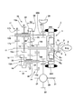
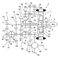
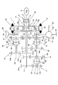
この発明は、好ましくは、前記キャリヤに連結された第1の駆動軸と、前記リングギヤに連結された第2の駆動軸とが、前記遊星歯車機構の中心軸線を中心として同心円上に配置され、これらの回転軸に前記各変速ギヤ対における駆動側のギヤが配置されている。 In the present invention, preferably, a first drive shaft connected to the carrier and a second drive shaft connected to the ring gear are arranged concentrically around a central axis of the planetary gear mechanism, Drive-side gears in each of the transmission gear pairs are disposed on these rotating shafts.
この発明によれば、第1の変速ギヤ対が第3の回転要素を介してエンジンに連結されているので、その第1の変速ギヤ対を出力部材に連結することにより、第1の変速ギヤ対による変速比が、いわゆるエンジン直結の状態で設定でき、また電動機の回転数を制御することにより差動機構の全体を一体となって回転させることにより、第2の変速ギヤ対とエンジンとが直結状態となるので、第2の変速ギヤ対を出力部材に連結することにより、第2の変速ギヤ対による変速比が、いわゆるエンジン直結の状態で設定することができる。すなわち、動力の変換などを伴うことなくエンジンの動力を出力部材に伝達してここから出力できるので、動力伝達効率が良好になる。また、出力部材に対するトルクの伝達を行うギヤ対を第1のギヤ対と第2のギヤ対との間で切り替える場合、電動機の回転数を変化させることにより、エンジン回転数などの回転数を変速後の回転数に同期させることができるので、ギヤ対の切替に伴う回転数の変化やそれに起因するショックを防止もしくは抑制することができ、また出力部材のトルクの一時的な低下を防止することができる。そして、各ギヤ対の構成やこれと出力部材との関係は、従来の手動変速機やいわゆるツインクラッチ式変速機と同様に構成することができ、これらの変速機におけるクラッチに相当する部分の構成を前記差動機構および電動機による構成に置き換えた構成とすることができるので、全体としての構成を小型化し、あるいは簡素化することができる。 According to this invention, since the first transmission gear pair is connected to the engine via the third rotating element, the first transmission gear pair is connected to the output member by connecting the first transmission gear pair to the output member. The gear ratio by the pair can be set in a so-called engine direct connection state, and the second differential gear pair and the engine are connected by rotating the entire differential mechanism integrally by controlling the rotation speed of the electric motor. Since the second transmission gear pair is connected to the output member, the gear ratio of the second transmission gear pair can be set in a so-called engine direct connection state. In other words, the power of the engine can be transmitted to the output member without being converted, and the power can be output therefrom, so that the power transmission efficiency is improved. Further, when the gear pair for transmitting torque to the output member is switched between the first gear pair and the second gear pair, the engine speed and other engine speeds are changed by changing the motor speed. Since it can be synchronized with the subsequent rotational speed, it is possible to prevent or suppress the rotational speed change and the shock caused by the switching of the gear pair, and to prevent a temporary decrease in the torque of the output member. Can do. The configuration of each gear pair and the relationship between the gear pair and the output member can be configured in the same manner as a conventional manual transmission or a so-called twin clutch transmission, and the configuration of the portion corresponding to the clutch in these transmissions Can be replaced with the configuration of the differential mechanism and the electric motor, so that the overall configuration can be reduced in size or simplified.
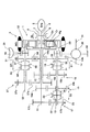
つぎにこの発明を更に具体的に説明する。この発明に係る動力伝達装置は、基本的には、エンジンが出力した動力を、互いにギヤ比が異なる複数の変速ギヤ対から選択された変速ギヤ対を介して出力部材に伝達し、ここから動力を出力するように構成されている。そのエンジンは、要は動力源であって、ガソリンエンジンやディーゼルエンジンなどの内燃機関がその典型的な例であるが、これに限らず、モータなどの他の動力装置であってもよい。また、変速ギヤ対は互いに常時噛み合っている駆動ギヤと被駆動ギヤ(従動ギヤ)とからなるギヤ対であり、従来の車両用の手動変速機やツインクラッチ式変速機などで採用されているギヤ対と同様の構成であってよい。また、その変速ギヤ対の数は複数であればよく、その数が多いほど、設定可能な変速比(もしくは変速段)の数が多くなって、エンジン回転数や駆動トルクを細かく制御することが可能になる。図1には、四対の変速ギヤ対を設けた例を示してある。 Next, the present invention will be described more specifically. The power transmission device according to the present invention basically transmits the power output from the engine to the output member through a transmission gear pair selected from a plurality of transmission gear pairs having different gear ratios. Is configured to output. The engine is basically a power source, and an internal combustion engine such as a gasoline engine or a diesel engine is a typical example, but is not limited thereto, and may be another power device such as a motor. The transmission gear pair is a gear pair composed of a driving gear and a driven gear (driven gear) that are always meshed with each other, and is used in a conventional manual transmission for a vehicle, a twin clutch transmission, and the like. The configuration may be the same as that of the pair. Further, the number of the transmission gear pairs may be plural, and the larger the number, the greater the number of speed ratios (or shift speeds) that can be set, and the engine speed and driving torque can be finely controlled. It becomes possible. FIG. 1 shows an example in which four pairs of transmission gears are provided.
この発明では、それらの変速ギヤ対を第1の変速ギヤ対と第2の変速ギヤ対とに分けてあり、エンジンの動力をそれら第1の変速ギヤ対または第2の変速ギヤ対から出力部材にに選択的に伝達するように構成されている。この発明に係る動力伝達装置は、その切り替えのための機構として差動機構を主体とした機構を備えている。より具体的には、その差動機構は、三つの回転要素によって差動作用を行う機構であり、シングルピニオン型遊星歯車機構やダブルピニオン型遊星歯車機構がその典型的な例であるが、これらの遊星歯車機構以外の機構であってもよい。なお、回転要素とは、差動機構を構成する要素のうち、外部の何らかの部材に連結することの可能な要素である。 In the present invention, these transmission gear pairs are divided into a first transmission gear pair and a second transmission gear pair, and engine power is output from the first transmission gear pair or the second transmission gear pair to the output member. It is configured to selectively communicate with each other. The power transmission device according to the present invention includes a mechanism mainly composed of a differential mechanism as a mechanism for switching. More specifically, the differential mechanism is a mechanism that performs a differential action by three rotating elements, and single pinion type planetary gear mechanism and double pinion type planetary gear mechanism are typical examples. It may be a mechanism other than the planetary gear mechanism. The rotating element is an element that can be connected to some external member among the elements constituting the differential mechanism.
差動機構における三つの回転要素は、その機能で分ければ、入力要素、出力要素、反力(もしくは固定)要素であり、入力要素に前記エンジンが連結される。出力要素には前述した変速ギヤ対における駆動側ギヤが配置される。そして、この発明における動力伝達装置では、反力要素に電動機が連結されている。この電動機は、電力が供給されて動力を出力するだけでなく、外力により駆動されて発電を行うモータ・ジェネレータによって構成されていることが好ましい。なお、エンジンはトルクを出力するだけでなく、燃料が供給されない非動作状態ではフリクショントルクを発生し、また電動機は発電機として機能した場合に負のトルクを発生し、さらに動力伝達装置が車両に搭載されて車輪に連結されている場合には出力部材から差動機構に動力が入力されることもあるので、上記の入力要素および出力要素ならびに反力要素は、いずれかの回転要素が固定的にそのような要素になるのではなく、動力伝達装置の動作の状態によって入力要素が反力要素に切り替わったり、反力要素が出力要素に切り替わったりする。 The three rotating elements in the differential mechanism are an input element, an output element, and a reaction force (or fixed) element, if divided according to their functions, and the engine is connected to the input element. The drive side gear in the transmission gear pair described above is disposed in the output element. And in the power transmission device in this invention, the electric motor is connected with the reaction force element. This electric motor is preferably constituted by a motor / generator which not only supplies electric power and outputs power but also is driven by an external force to generate electric power. The engine not only outputs torque, but also generates friction torque in a non-operating state where fuel is not supplied, and the motor generates negative torque when functioning as a generator, and the power transmission device is applied to the vehicle. When mounted and connected to wheels, power may be input from the output member to the differential mechanism, so any of the rotating elements of the above input element, output element, and reaction force element are fixed. However, the input element is switched to the reaction force element or the reaction force element is switched to the output element depending on the operation state of the power transmission device.
また、この発明の好ましい実施の形態によれば、差動機構の全体を、電動機によらずにロック用係合機構によって一体化させることができるので、前記第1の変速ギヤ対による変速比を設定した場合の動力伝達効率が更に良好になる。 According to a preferred embodiment of the present invention, the entire differential mechanism can be integrated by the locking engagement mechanism without using the electric motor, so that the gear ratio by the first transmission gear pair is increased. The power transmission efficiency when set is further improved.
この発明の他の好ましい実施の形態によれば、前記出力部材に動力を出力し始める発進時に前記第2の変速ギヤ対を前記第3の回転要素および出力部材に連結するとともに前記差動機構に差動作用を生じさせ、かつ発進後に前記差動機構の差動作用を阻止するよう前記差動機構をロックさせる発進手段を備えているので、エンジンが駆動している状態で電動機のトルクあるいは回転数を変化させることにより、第3の回転要素およびこれに連結されている第2のギヤ対のトルクや回転数を変化させることができる。したがって、エンジンを駆動している状態で電動機を制御することにより第3の回転要素を停止させておき、その状態から電動機を制御することにより第3の回転要素から出力するトルクを次第に増大させることができる。その後、差動機構をロック状態にしてエンジンと第2の変速ギヤ対をいわゆる直結状態とすることができる。そのため、出力部材の回転が止まっている状態でもエンジンの回転を維持させるための特別な機構もしくは発進のための特別な機構を設ける必要がなく、装置の全体としての構成を簡素化することができる。 According to another preferred embodiment of the present invention, the second transmission gear pair is connected to the third rotating element and the output member at the start of starting to output power to the output member, and is connected to the differential mechanism. There is a starting means for locking the differential mechanism so as to cause a differential action and prevent the differential action of the differential mechanism after starting, so that the torque or rotation of the motor can be performed while the engine is driven. By changing the number, the torque and the number of rotations of the third rotation element and the second gear pair connected to the third rotation element can be changed. Therefore, the third rotating element is stopped by controlling the electric motor while the engine is driven, and the torque output from the third rotating element is gradually increased by controlling the electric motor from that state. Can do. Thereafter, the differential mechanism can be locked to bring the engine and the second transmission gear pair into a so-called direct connection state. Therefore, there is no need to provide a special mechanism for maintaining the rotation of the engine or a special mechanism for starting even when the rotation of the output member is stopped, and the overall configuration of the apparatus can be simplified. .
この発明の更に他の好ましい実施の形態によれば、前記エンジンが非動作の状態で前記いずれかの変速ギヤ対を前記出力部材およびいずれかの回転要素に連結し、かつ前記電動機を動作させ、さらに前記差動機構の差動作用を阻止するよう前記差動機構をロックさせる電動・回生手段を更に備えていることにより、いずれかの変速ギヤ対を介して出力部材が差動機構に対してトルク伝達可能な状態に連結され、かつその差動機構の差動作用が阻止されてその全体が一体となって回転するので、この差動機構に連結されている電動機と出力部材とが、いずれかの変速ギヤ対を介していわゆる直結された状態となる。したがって、電動機に通電してこれを駆動すれば、その動力を出力部材から出力することができ、また出力部材の動力を電動機に伝達してこれを強制的に駆動することにより、電動機を発電機として機能させてエネルギ回生を行うことができる。 According to still another preferred embodiment of the present invention, the transmission gear pair is connected to the output member and any rotation element while the engine is not operated, and the electric motor is operated. Furthermore, by further comprising electric / regenerative means for locking the differential mechanism so as to prevent the differential action of the differential mechanism, the output member is connected to the differential mechanism via one of the transmission gear pairs. Since it is connected in a state where torque can be transmitted and the differential action of the differential mechanism is blocked and the whole rotates integrally, the electric motor and output member connected to the differential mechanism A so-called direct connection state is established through the transmission gear pair. Therefore, if the motor is energized and driven, the power can be output from the output member, and the power of the output member is transmitted to the motor and forcibly driven to thereby drive the motor to the generator. Energy regeneration can be performed.
さらに、この発明の他の好ましい実施の形態によれば、前記エンジンが非動作の状態で前記第2の変速ギヤ対を前記出力部材および前記第3の回転要素に連結し、かつ前記電動機を動作させ、さらに前記差動機構の差動作用を行わせるよう前記差動機構をフリー状態に設定する電動・回生手段を更に備えているので、エンジンが非作動状態であることにより、エンジンの抵抗力が第1の回転要素に反力として作用する。したがって、その状態で差動機構を差動作用の生じるフリーな状態にし、かつ第2の変速ギヤ対を出力部材に対してトルク伝達可能な状態に連結することにより、電動機の出力したトルクを出力部材に伝達することができ、また出力部材の動力を電動機に伝達することができる。その結果、第2の変速ギヤ対による変速比を設定した状態で、電動機に通電してこれを駆動すれば、その動力を出力部材から出力することができ、また出力部材の動力を電動機に伝達してこれを強制的に駆動することにより、電動機を発電機として機能させてエネルギ回生を行うことができる。 Furthermore, according to another preferred embodiment of the present invention, the second transmission gear pair is connected to the output member and the third rotating element while the engine is inactive, and the motor is operated. And further includes electric / regenerative means for setting the differential mechanism to a free state so as to cause the differential mechanism to perform a differential action. Acts as a reaction force on the first rotating element. Accordingly, in this state, the differential mechanism is set in a free state in which differential action occurs, and the second transmission gear pair is connected to a state in which torque can be transmitted to the output member, thereby outputting the torque output by the motor. The power can be transmitted to the member, and the power of the output member can be transmitted to the electric motor. As a result, when the motor is energized and driven in a state where the gear ratio by the second transmission gear pair is set, the power can be output from the output member, and the power of the output member is transmitted to the motor. By forcibly driving it, the motor can function as a generator to perform energy regeneration.
この発明では、好ましくは、前記電動・回生手段は、前記電動機の回転数が前記エンジンの回転数より高回転数であり、かつ前記電動機のトルクが前記エンジンのフリクショントルクと釣り合っている場合に、前記差動機構をフリー状態に設定する手段を含んでおり、したがって差動機構の第1の回転要素に反力として作用するエンジンのフリクショントルクが、第2の回転要素に連結されている電動機のトルクと釣り合い、かつその状態で電動機の回転数がエンジンの回転数より高回転数であるから、出力部材から伝達される動力によって電動機を回転させてこれを発電として機能させるエネルギ回生時には、電動機で電力に変換する割合が多くなり、例えば差動機構をロック状態にして電動機によってエネルギ回生する場合より回生効率が向上する。 In the present invention, preferably, the electric / regenerative means is configured such that the rotational speed of the electric motor is higher than the rotational speed of the engine, and the torque of the electric motor is balanced with the friction torque of the engine. Means for setting the differential mechanism to a free state, and therefore the friction torque of the engine acting as a reaction force on the first rotating element of the differential mechanism is connected to the second rotating element. Since the rotational speed of the motor is balanced with the torque and is higher than the rotational speed of the engine in that state, the motor is rotated by the power transmitted from the output member and functions as power generation. The rate of conversion to electric power increases. For example, the regeneration efficiency is higher than when the energy is regenerated by the motor with the differential mechanism locked. To improve.
この発明のまた他の好ましい実施の形態によれば、前記出力部材は、互いに平行に配置された二本の出力軸を含み、それらの出力軸上に前記変速ギヤ対における被駆動側のギヤが分散して配置されているので、被駆動側のギヤを配置する出力軸が二本設けられていることにより、軸線方向に配列する被駆動側のギヤの数が少なくなるから、出力軸を相対的に短くでき、その結果、装置の全体としての構成を小型化することができる。 According to still another preferred embodiment of the present invention, the output member includes two output shafts arranged in parallel to each other, and a driven-side gear in the transmission gear pair is disposed on the output shafts. Since the two output shafts for arranging the driven side gears are provided in a distributed manner, the number of driven side gears arranged in the axial direction is reduced. As a result, the overall configuration of the apparatus can be reduced in size.
また、この発明の好ましい実施の形態によれば、隣接する変速比(もしくは変速段)を設定する変速ギヤ対は、互いに異なる回転要素および出力軸に連結される構成であるから、最大変速比を第1変速比(もしくは第1変速段)とし、これに隣接する変速機を第2変速比(もしくは第2変速段)とした場合の奇数変速比(もしくは奇数変速段)を設定するための二つの変速ギヤ対、あるいは偶数変速比(もしくは偶数変速段)を設定するための二つの変速ギヤ対を、それら二つの変速ギヤ対の間に配置した一つの連結機構によって出力部材もしくはいずれかの回転要素に選択的に連結するように構成することができる。その結果、部品点数を少なくして装置の全体としての構成を小型化、簡素化することができる。 Further, according to a preferred embodiment of the present invention, the transmission gear pairs for setting adjacent transmission gear ratios (or gear speeds) are connected to different rotary elements and output shafts, so that the maximum transmission gear ratio is set. Two for setting an odd gear ratio (or odd gear) when the first gear ratio (or the first gear) is set and the transmission adjacent to the first gear ratio is the second gear ratio (or the second gear). Two transmission gear pairs, or two transmission gear pairs for setting an even transmission ratio (or even transmission speed), are rotated by an output member or any one of them by one coupling mechanism arranged between the two transmission gear pairs. It can be configured to selectively connect to elements. As a result, the number of parts can be reduced, and the overall configuration of the apparatus can be reduced in size and simplified.
そしてまた、この発明の他の好ましい実施の形態によれば、前記各出力軸上に配置された前記被駆動側のギヤをそれぞれの出力軸に選択的に連結するクラッチ機構が前記各出力軸上に配置され、かつ一方の出力軸上のクラッチ機構と他方の出力軸上のクラッチ機構とはそれぞれの出力軸上の被駆動側のギヤに対して軸線方向で互いに反対側に配置されているから、一方の出力軸上のクラッチ機構と、他方の出力軸上のクラッチ機構とは、軸線方向での位置が互いにずれており、半径方向で互いに重なることがないので、いわゆる軸間距離を短くして装置の全体としての構成を小型化することができる。 According to another preferred embodiment of the present invention, a clutch mechanism for selectively connecting the driven gear disposed on each output shaft to each output shaft is provided on each output shaft. And the clutch mechanism on one output shaft and the clutch mechanism on the other output shaft are arranged on opposite sides in the axial direction with respect to the driven gear on each output shaft. The clutch mechanism on one output shaft and the clutch mechanism on the other output shaft are offset from each other in the axial direction and do not overlap each other in the radial direction. Thus, the overall configuration of the apparatus can be reduced in size.
またさらにこの発明の好ましい実施の形態によれば、前進駆動のための六つの変速ギヤ対を備え、この変速ギヤ対のうちの四つの変速ギヤ対における被駆動側のギヤが一方の前記出力軸上に該一方の出力軸に対して選択的に連結されるように配置され、かつ前記六つの変速ギヤ対のうちの二つの変速ギヤ対における被駆動側のギヤが他方の前記出力軸上に該他方の出力軸に対して選択的に連結されるように配置されているので、あるいは最大ギヤ比の変速ギヤ対と最小ギヤ比の変速ギヤ対とが隣接して配置されるとともにこれらの変速ギヤ対を前記一方の出力軸に対して選択的にトルク伝達可能にする第1クラッチ機構と、前記最大ギヤ比に対してギヤ比が二段分小さい第1奇数段用変速ギヤ対と該第1奇数段用変速ギヤ対に対してギヤ比が二段分小さい第2奇数段用変速ギヤ対とが隣接して配置されるとともにこれらの奇数段用変速ギヤ対を前記他方の出力軸に対して選択的にトルク伝達可能にする第2クラッチ機構と、前記最大ギヤ比に対してギヤ比が一段分小さい第1偶数段用変速ギヤ対と該第1偶数段用変速ギヤ対に対してギヤ比が二段分小さい第2偶数段用変速ギヤ対とが隣接して配置されるとともにこれらの偶数段用変速ギヤ対を前記一方の出力軸に対して選択的にトルク伝達可能にする第3クラッチ機構とを更に備えているので、同軸上の各ギヤの間に、出力軸に連結するためのクラッチ機構を配置することができ、そのためクラッチ機構の数を少なくして装置の全体としての構成を小型化することができる。 Still further, according to a preferred embodiment of the present invention, six transmission gear pairs for forward driving are provided, and the driven gear in the four transmission gear pairs of the transmission gear pairs is one of the output shafts. The driven gear in the two transmission gear pairs of the six transmission gear pairs is arranged on the other output shaft. Since it is arranged so as to be selectively connected to the other output shaft, or the transmission gear pair with the maximum gear ratio and the transmission gear pair with the minimum gear ratio are arranged adjacent to each other, A first clutch mechanism capable of selectively transmitting torque to the one output shaft; a first odd-speed transmission gear pair having a gear ratio that is two steps smaller than the maximum gear ratio; 1 Gear ratio for odd-numbered transmission gear pair A second clutch mechanism that is arranged adjacent to a second odd-numbered transmission gear pair that is smaller than the first gear and that selectively transmits torque to the other output shaft. , A first even-numbered transmission gear pair having a gear ratio that is one step smaller than the maximum gear ratio, and a second even-numbered transmission gear pair having a gear ratio that is two steps smaller than the first even-numbered transmission gear pair. And a third clutch mechanism for selectively transmitting torque to these one output shaft with respect to the one output shaft. A clutch mechanism for coupling to the output shaft can be disposed between the gears. Therefore, the number of clutch mechanisms can be reduced and the overall configuration of the apparatus can be reduced in size.
さらにこの発明の好ましい実施の形態によれば、前記差動機構から伝達されるトルクを、前記各変速ギヤ対を介して前記出力部材に伝達されるトルクとは反対方向のトルクにして出力するリバース機構を更に備えているので、エンジンの回転方向が一定であっても、出力部材に現れるトルクの方向を、各変速ギヤ対を介してトルクを伝達した場合の方向とは異ならせることができる。したがって車両に搭載した場合には後進走行することができる。 Furthermore, according to a preferred embodiment of the present invention, the torque transmitted from the differential mechanism is output as a torque in a direction opposite to the torque transmitted to the output member via each transmission gear pair. Since the mechanism is further provided, even if the rotational direction of the engine is constant, the direction of the torque appearing on the output member can be made different from the direction in which the torque is transmitted through each transmission gear pair. Therefore, when mounted on a vehicle, the vehicle can travel backward.
そのリバース機構は、この発明の好ましい実施の形態では、前記出力部材を前記第3の回転要素に選択的に連結する切替機構を備えており、したがっていわゆるリバース状態を設定した場合、前述したこの発明の好ましい実施の形態と同様に、発進の際に差動機構による差動作用を生じさせることができ、発進のための特別な機構を必要とすることなく、スムースなリバース発進が可能になる。 In the preferred embodiment of the present invention, the reverse mechanism includes a switching mechanism that selectively connects the output member to the third rotating element. Therefore, when the so-called reverse state is set, the present invention described above is provided. As in the preferred embodiment of the present invention, a differential action by a differential mechanism can be generated at the time of starting, and a smooth reverse starting is possible without requiring a special mechanism for starting.
この発明の更に他の好ましい実施の形態によれば、前記エンジンを前記差動機構における前記第1の回転要素に対してトルクを伝達しないように切り離す遮断機構を更に備えているので、エンジンを差動機構から切り離すことができるので、電動機の動力を出力部材に出力する場合や、出力部材から伝達した動力で電動機を回転させる場合に、エンジンが連れ回ることを回避できる。 According to still another preferred embodiment of the present invention, the engine further includes a shut-off mechanism for separating the engine so as not to transmit torque to the first rotating element in the differential mechanism. Since it can be separated from the moving mechanism, it is possible to avoid the engine from being accompanied when the power of the motor is output to the output member or when the motor is rotated by the power transmitted from the output member.
その遮断機構は、この発明の好ましい実施の形態によれば、前記エンジンと前記第1の回転要素との連結を解きかつ前記差動機構におけるいずれかの回転要素同士を連結して前記差動機構をロック状態にする第1の動作位置と、前記エンジンと前記第1の回転要素とを連結しかつ前記差動機構におけるいずれかの回転要素同士を連結して前記差動機構をロック状態にする第2の動作位置と、前記エンジンと前記第1の回転要素とを連結しかつ前記差動機構におけるいずれかの回転要素同士の連結を解いて前記差動機構をフリー状態にする第3の動作位置とに選択的に設定可能な選択係合機構を含むから、一つの選択係合機構によって上述した三つの動力伝達状態もしくは動作状態に切り替えることができ、動力伝達状態もしくは動作状態を切り替えるシフト機構の構成を簡素化することができる。 According to a preferred embodiment of the present invention, the shut-off mechanism is configured such that the engine and the first rotating element are uncoupled and any of the rotating elements in the differential mechanism are coupled to each other. The first operating position for locking the engine, the engine and the first rotating element are connected, and any of the rotating elements in the differential mechanism are connected to bring the differential mechanism into the locked state. A third operation for connecting the second operating position, the engine and the first rotating element, and releasing any of the rotating elements in the differential mechanism to bring the differential mechanism into a free state. Since it includes a selective engagement mechanism that can be selectively set to the position, it can be switched to the three power transmission states or operation states described above by one selective engagement mechanism, and the power transmission state or operation state can be switched off. It is possible to simplify the configuration of the changing shift mechanism.
またそして、この発明の好ましい実施の形態によれば、前記電動機の回転を阻止する電動機ロック機構を更に備えているので、電動機は差動機構の第2の回転要素に連結されているので、電動機をロックすることにより第2の回転要素の回転を阻止することになり、したがってその状態では差動機構が変速機として機能し、エンジンの出力したトルクを増幅もしくは減少させて差動機構から出力することになる。その結果、差動機構による変速と変速ギヤ対による変速とを重畳的に生じさせることが可能になるので、設定可能な変速比(もしくは変速段)を、変速ギヤ対の数以上に増大させることができる。また、電動機のロックを解除することにより、トルクの伝達に関与する変速ギヤ対を切り替える変速の際に、変速後のギヤ対の回転数を変速前の回転数に合わせる同期制御を電動機によって行うことができる。 In addition, according to a preferred embodiment of the present invention, since the motor further includes a motor lock mechanism that prevents the motor from rotating, the motor is connected to the second rotating element of the differential mechanism. Is locked to prevent the rotation of the second rotating element. Therefore, in this state, the differential mechanism functions as a transmission, and the torque output from the engine is amplified or reduced and output from the differential mechanism. It will be. As a result, the shift by the differential mechanism and the shift by the transmission gear pair can be generated in a superimposed manner, so that the settable gear ratio (or shift speed) is increased to be greater than the number of transmission gear pairs. Can do. In addition, when the shift of the transmission gear pair involved in torque transmission is changed by releasing the lock of the electric motor, synchronous control for adjusting the rotation speed of the gear pair after the shift to the rotation speed before the shift is performed by the motor. Can do.
その電動機ロック機構は、この発明の好ましい実施の形態によれば、前記第2の変速ギヤ対が前記第3の回転要素と前記出力部材とに連結される場合に前記電動機の回転を阻止する機構を含んでいるから、電動機をロックすることによりこれが連結された第2の回転要素が固定要素となり、エンジンが連結されている第1の回転要素が入力要素、第3の回転要素が出力要素になるので、第3の回転要素が第2の変速ギヤ対を介して出力部材に連結されることにより、エンジンが出力した動力が、差動機構および第2の変速ギヤ対の変速作用を受けて出力部材に伝達される。これは、エンジンと出力部材とを機械的に直結した状態であり、効率良く動力を伝達することができる。 According to a preferred embodiment of the present invention, the motor lock mechanism is a mechanism that prevents rotation of the motor when the second transmission gear pair is connected to the third rotation element and the output member. Therefore, by locking the electric motor, the second rotating element connected thereto becomes a fixed element, the first rotating element connected to the engine is an input element, and the third rotating element is an output element. Therefore, when the third rotating element is connected to the output member via the second speed change gear pair, the power output by the engine is subjected to the speed change action of the differential mechanism and the second speed change gear pair. It is transmitted to the output member. This is a state in which the engine and the output member are mechanically directly connected, and power can be transmitted efficiently.
さらにこの発明の好ましい実施の形態によれば、前記エンジンの回転を阻止するエンジンロック機構を更に備えているので、電動機が出力する動力を出力部材に伝達する場合や、出力部材から電動機に動力を伝達する場合に、エンジンが連れ回ることを回避してエンジンで動力が消費されることを防止でき、その結果、エネルギ効率を向上させることができる。 Furthermore, according to a preferred embodiment of the present invention, since the engine lock mechanism for preventing the engine from rotating is further provided, the power output from the motor is transmitted to the output member, or the power is transmitted from the output member to the motor. In the case of transmission, it is possible to prevent the engine from being carried around and prevent the power from being consumed by the engine. As a result, the energy efficiency can be improved.
そのエンジンロック機構は、この発明の好ましい実施の形態によれば、前記第2の変速ギヤ対を前記第3の回転要素と前記出力部材とに連結しかつ前記電動機を動作させている場合に前記エンジンの回転を阻止する機構を含むので、電動機が動力を出力するように動作させ、あるいは発電機として動作させる場合に、エンジンをロックするので、電動機と出力部材とが差動機構を介して連結され、その際にエンジンの連れ回りが阻止されるから、電動機と出力部材との間の動力の伝達効率を向上させることができる。 According to a preferred embodiment of the present invention, the engine lock mechanism is configured to connect the second transmission gear pair to the third rotating element and the output member and operate the electric motor when the motor is operated. Since it includes a mechanism that prevents the engine from rotating, the motor is locked when the motor is operated to output power or is operated as a generator, so the motor and the output member are connected via a differential mechanism. In this case, since the engine is prevented from rotating, the power transmission efficiency between the electric motor and the output member can be improved.
また、そのエンジンロック機構は、この発明の他の好ましい実施の形態によれば、前記エンジンの回転を阻止する第1の動作位置と、前記差動機構におけるいずれかの回転要素同士を連結して前記差動機構をロック状態にする第2の動作位置と、前記電動機の回転を阻止する電動機ロック位置とに選択的に設定可能な機構を含むので、エンジンのロックや差動機構のロック、さらには電動機のロックを一つの機構で行うことが可能になるので、そのための機構の構成を簡素化し、ひいては装置の全体としての構成を小型化することが可能になる。 According to another preferred embodiment of the present invention, the engine lock mechanism connects the first operating position for preventing the rotation of the engine and any of the rotating elements in the differential mechanism. Since it includes a mechanism that can be selectively set to a second operation position that locks the differential mechanism and a motor lock position that prevents rotation of the motor, the engine lock and the differential mechanism lock, Since the electric motor can be locked by one mechanism, the structure of the mechanism for that purpose can be simplified, and as a result, the overall structure of the apparatus can be reduced in size.
そして、この発明の更に他の好ましい実施の形態によれば、前記差動機構は、外歯歯車であるサンギヤと、そのサンギヤに対して同心円上に配置された内歯歯車であるリングギヤと、これらサンギヤとリングギヤとの間に配置されたピニオンギヤを自転かつ公転自在に保持するキャリヤとを回転要素とする遊星歯車機構を含み、前記キャリヤに前記エンジンが連結され、かつ前記サンギヤに前記電動機が連結されるように構成されており、またそのキャリヤに連結された第1の駆動軸と、前記リングギヤに連結された第2の駆動軸とが、前記遊星歯車機構の中心軸線を中心として同心円上に配置され、これらの回転軸に前記各変速ギヤ対における駆動側のギヤが配置されているので、差動機構が遊星歯車機構によって構成されていることにより、必要とする軸数を少なくすることが可能になり、また半径方向の寸法を相対的に小さくすることができるので、装置の全体としての構成を小型化することが可能になる。 According to still another preferred embodiment of the present invention, the differential mechanism includes a sun gear that is an external gear, a ring gear that is an internal gear arranged concentrically with the sun gear, and these A planetary gear mechanism having a rotating element and a carrier that rotatably and revolves a pinion gear disposed between a sun gear and a ring gear, the engine being connected to the carrier, and the electric motor being connected to the sun gear The first drive shaft connected to the carrier and the second drive shaft connected to the ring gear are arranged concentrically around the central axis of the planetary gear mechanism. Since the drive-side gears in each of the transmission gear pairs are arranged on these rotating shafts, the differential mechanism is constituted by a planetary gear mechanism. , It is possible to reduce the number of axes required, also can be reduced relative radial dimensions, it is possible to miniaturize the configuration of the entire device.
図1にはシングルピニオン型遊星歯車機構を主体に構成した差動機構を示してある。図1に示す構成について説明すると、この発明における差動機構に相当するシングルピニオン型の遊星歯車機構1は、外歯歯車であるサンギヤSnと、そのサンギヤSnに対して同心円上に配置された内歯歯車であるリングギヤRgと、これらサンギヤSnとリングギヤRgとに噛み合った状態に配置されているピニオンギヤを自転かつ公転自在に保持しているキャリヤCrとを備えている。
FIG. 1 shows a differential mechanism mainly composed of a single pinion type planetary gear mechanism. The configuration shown in FIG. 1 will be described. A single pinion type
そのキャリヤCrにエンジン(Eng)2が連結されている。このエンジン2と遊星歯車機構1とは、同一軸線上に配置されていることが好ましいが、これらを互いに異なる軸線上に配置して、歯車機構やチェーンなどの伝動機構を介して両者を連結してもよい。また、サンギヤSnにこの発明の電動機に相当するモータ・ジェネレータ(MG)3が連結されている。このモータ・ジェネレータ3は、例えば永久磁石式の同期電動機であって、そのロータがサンギヤSnに連結され、ステータは図示しないケーシングなどの固定部に固定されている。さらにモータ・ジェネレータ3は全体として環状もしくは円筒状をなしており、その内周側に前記遊星歯車機構1が配置されている。すなわち、モータ・ジェネレータ3と遊星歯車機構1とは軸線方向でほぼ同じ位置に配置されており、両者が半径方向で少なくとも一部、重なっている(オーバーラップしている)。これは、モータ・ジェネレータ3の外径を相対的に大きくして高トルク化するとともに、エンジン2側に径の大きい部分を配置してスペースを有効に利用するためである。
An engine (Eng) 2 is connected to the carrier Cr. The
そして、モータ・ジェネレータ3は、インバータなどのコントローラ4を介して二次電池などの蓄電装置5に接続されている。そのコントローラ4は、モータ・ジェネレータ3に対して供給する電流もしくは電圧などを変化させてモータ・ジェネレータ3の出力トルクや回転数を制御し、またモータ・ジェネレータ3が外力によって強制的に回転させられる場合の発電量や発電に要するトルクなどを制御するように構成されている。
The motor /
モータ・ジェネレータ3を上記のように制御することにより、これが連結されているサンギヤSnの回転数を制御することができ、その回転数制御によってサンギヤSnの回転数をキャリヤCrやリングギヤRgの回転数と一致させれば、遊星歯車機構1は差動状態とならず、その全体が一体となって回転する。このような一体回転状態を電力を消費せずに設定するためのロック用係合機構が設けられている。このロック用係合機構は、遊星歯車機構1における少なくとも二つの回転要素を連結することにより、その全体を一体化するように構成された連結機構であり、噛み合いクラッチ(ドグクラッチ)や摩擦クラッチなどによって構成されている。
By controlling the motor /
図1に示す例では、キャリヤCrとサンギヤSnとを選択的に連結するロック用係合機構(ロッククラッチ)SLが設けられている。これは、一例として、スリーブをスプラインに噛み合わせることによりキャリヤCrとサンギヤSnとを連結するドグクラッチによって構成されている。その構成を簡単に説明すると、キャリヤCrをエンジン2に連結している入力軸6にハブ7が設けられており、そのハブ7の外周面に形成したスプラインにスリーブ8が軸線方向に移動でき、かつ回転方向に一体化された状態で嵌合している。そのスリーブ8が嵌合することのできるスプライン9が、サンギヤSnと一体の部材もしくはサンギヤSnとモータ・ジェネレータ3のロータとを連結している部材に形成されている。したがって、スリーブ8をサンギヤSn側に移動させてそのスプライン9に嵌合させることにより、キャリヤCrとサンギヤSnとが少なくとも回転方向で連結されるようになっている。スリーブ8をその軸線方向に往復動させるためのアクチュエータ10が設けられている。このアクチュエータ10は、油圧式あるいは電動式のいずれでもよい。
In the example shown in FIG. 1, a locking engagement mechanism (lock clutch) SL for selectively connecting the carrier Cr and the sun gear Sn is provided. As an example, this is constituted by a dog clutch that connects the carrier Cr and the sun gear Sn by engaging the sleeve with the spline. Briefly describing the configuration, a
上記の遊星歯車機構1を挟んでエンジン2とは反対側に第1駆動軸11と第2駆動軸12とが配置されている。第1駆動軸11は、遊星歯車機構1の中心軸線と同一の軸線上に回転自在に配置されており、その一端部でキャリヤCrに連結されている。そのキャリヤCrには前述したようにエンジン2が連結されているから、結局、第1駆動軸11はエンジン2にも連結されている。第2駆動軸12は、第1駆動軸11の外周側に嵌合し、かつ第1駆動軸11と相対回転可能に配置されており、この第2駆動軸12はその一端部で前記リングギヤRgに連結されている。したがって図1に示す例では、キャリヤCrがこの発明の第1の回転要素に相当し、またサンギヤSnがこの発明の第2の回転要素に相当し、さらにリングギヤRgがこの発明の第3の回転要素に相当している。
A
第1駆動軸11は中空軸である第2駆動軸12より長く、したがって第1駆動軸11は第2駆動軸12から突出している。これらの駆動軸11,12と平行に、この発明における出力部材に相当する出力軸13が回転自在に配置されており、この出力軸13と各駆動軸11,12との間に四対の変速ギヤ対14,15,16,17が設けられている。これらの各変速ギヤ対14,15,16,17は、それぞれ駆動ギヤ14a,15a,16a,17aとこれに常時噛み合っている被駆動ギヤ14b,15b,16b,17bとを備えており、それぞれの駆動ギヤ14a,15a,16a,17aと被駆動ギヤ14b,15b,16b,17bとの歯数の比すなわちギヤ比が互いに異なっている。すなわち、これらの変速ギヤ対14,15,16,17は、第1速ないし第4速の各変速比(変速段)を設定するためのものであって、ここに挙げてある順にギヤ比が小さく設定されている。
The
ギヤ比が最大の第1速用ギヤ対14における駆動ギヤ14aと、ギヤ比としては第1速用ギヤ対14に対して一つおいた第3速用ギヤ対16における駆動ギヤ16aとが、第2駆動軸12に取り付けられており、ギヤ比としては第1速ギヤ対14に隣接する第2速用ギヤ対15における駆動ギヤ15aと、最小のギヤ比である第4速用ギヤ対17における駆動ギヤ17aとが、第1駆動軸11の前記第2駆動軸12から突出した部分に取り付けられている。すなわち、奇数段を設定するための変速ギヤ対14,16が一方の駆動軸12と出力軸13との間に配置され、偶数段を設定するための変速ギヤ対15,17が他方の駆動軸11と出力軸13との間に配置されている。
The
各変速ギヤ対14,15,16,17における被駆動ギヤ14b,15b,16b,17bは、出力軸13に対して回転自在の状態で出力軸13上に配列されている。したがって、被駆動ギヤ14b,15b,16b,17bの出力軸13上での配列は、図1の右側から、第1速被駆動ギヤ14b、第3速被駆動ギヤ16b、第2速被駆動ギヤ15b、第4速被駆動ギヤ17bの順である。
The driven gears 14 b, 15 b, 16 b, 17 b in each of the transmission gear pairs 14, 15, 16, 17 are arranged on the
これらの変速ギヤ対14,15,16,17は、出力軸13に対して選択的に連結されるように構成されており、そのためのクラッチ機構が設けられている。このクラッチ機構は、ドグクラッチや摩擦クラッチなどの適宜の構造のものでよいが、図1にはドグクラッチの例が示されている。また、そのドグクラッチは、第1速被駆動ギヤ14bと第3速被駆動ギヤ16bとの間、および第2速被駆動ギヤ15bと第4速被駆動ギヤ17bとの間の二箇所に設けられている。
These transmission gear pairs 14, 15, 16, and 17 are configured to be selectively connected to the
第1速被駆動ギヤ14bと第3速被駆動ギヤ16bとを出力軸13に対して選択的に連結する奇数段用クラッチS1は、遊星歯車機構1の全体を一体化するように遊星歯車機構1をロックする前記ロッククラッチSLと同様な構成であって、出力軸13と一体のハブ18に軸線方向に前後動自在にスプライン嵌合されているスリーブ19と、そのハブ18を挟んだ両側に位置しかつ第1速被駆動ギヤ14bに一体のスプライン20および第3速被駆動ギヤ16bに一体のスプライン21とを備えている。したがって、スリーブ19が第1速被駆動ギヤ14b側に移動してそのスプライン20に嵌合することにより、第1速被駆動ギヤ14bがスリーブ19およびハブ18を介して出力軸13に連結されるように構成されている。また、スリーブ19が第3速被駆動ギヤ16b側に移動してそのスプライン21に嵌合することにより、第3速被駆動ギヤ16bがスリーブ19およびハブ18を介して出力軸13に連結されるように構成されている。
The odd-numbered stage clutch S1 that selectively connects the first speed driven
第2速被駆動ギヤ15bと第4速被駆動ギヤ17bとを出力軸13に対して選択的に連結する偶数段用クラッチS2も上記の奇数段用クラッチS1と同様に構成されている。すなわち、出力軸13と一体のハブ22に軸線方向に前後動自在にスプライン嵌合されているスリーブ23と、そのハブ22を挟んだ両側に位置しかつ第2速被駆動ギヤ15bに一体のスプライン24および第4速被駆動ギヤ17bに一体のスプライン25とを備えている。したがって、スリーブ23が第2速被駆動ギヤ15b側に移動してそのスプライン24に嵌合することにより、第2速被駆動ギヤ15bがスリーブ23およびハブ22を介して出力軸13に連結されるように構成されている。また、スリーブ23が第4速被駆動ギヤ17b側に移動してそのスプライン25に嵌合することにより、第4速被駆動ギヤ17bがスリーブ23およびハブ22を介して出力軸13に連結されるように構成されている。
The even-numbered clutch S2 that selectively connects the second-speed driven
そして、奇数段用のドグクラッチS1および偶数段用クラッチS2における各スリーブ19,23を軸線方向に前後動させるアクチュエータ26,27が設けられている。これらのアクチュエータ26,27は、油圧式あるいは電動式のいずれでもよい。
上記の出力軸13は、その遊星歯車機構1側の端部に設けられたカウンタギヤ28を介して終減速機として機能するデファレンシャル29に連結されている。このデファレンシャル29は、カウンタギヤ28に噛み合っているリングギヤ30と一体のデフケースの内部にピニオンギヤを取り付け、そのピニオンギヤに噛み合っている一対のサイドギヤ(それぞれ図示せず)を設けた公知の構成の歯車機構であり、そのサイドギヤのそれぞれに車輪(図示せず)にトルクを伝達する左右の車軸31が連結されている。したがって、図1に示す構成の動力伝達装置は、車両におけるトランスアクスルとして構成されている。
The
そして、前述したコントローラ4や各アクチュエータ10,26,27に制御指令信号を出力して駆動モードの設定や変速などを制御する電子制御装置(ECU)32が設けられている。この電子制御装置32は、マイクロコンピュータを主体として構成され、アクセル開度などの駆動要求量や車速、エンジン回転数、設定されている変速比などの入力データと、変速線図(変速マップ)などの予め記憶しているデータとに基づいて演算を行い、その演算結果に基づく制御指令信号を出力するように構成されている。
An electronic control unit (ECU) 32 is provided that outputs a control command signal to the
上記の動力伝達装置は、変速段用のいずれかのクラッチS1,S2によって出力軸13に対して第1駆動軸11もしくは第2駆動軸12をトルク伝達可能に連結し、またその駆動軸11,12のいずれかに対するエンジン2からのトルクの伝達を遊星歯車機構1によって切り替えることにより所定の変速段を設定する。また、そのいずれかのクラッチS1,S2を切り替え動作させて変速を行う場合に、遊星歯車機構1およびモータ・ジェネレータ3によって、ギヤの回転数を変速後の回転数に合わせる同期制御を行う。
In the power transmission device, the
その動作を説明すると、図2はエンジン2を出力軸13に対して機械的に直結して設定される変速比である変速段と、それらの変速段を設定するための各クラッチSL,S1,S2の動作状態をまとめて示す図表であり、○を付した数字は、図1に記載してある丸付きの数字と対応しており、変速段用のクラッチS1,S2におけるスリーブ19,23の移動方向もしくは位置あるいは係合している変速ギヤ対の番号を示している。また図2における「×」印は解放状態であって連結もしくはロックを行っていないこと、「○」印は、ロッククラッチSLが係合状態であって遊星歯車機構1をロックしていることを示している。
The operation will be described below. FIG. 2 shows a gear ratio which is a gear ratio set by mechanically connecting the
第1速を設定し、かつ第1速で発進する場合、エンジン2が始動されて回転しているので、遊星歯車機構1におけるキャリヤCrが正回転しているが、モータ・ジェネレータ3の電流制御を行って自由回転させ、もしくはサンギヤSnに反力が生じないように回転させる。こうすることにより、出力要素であるリングギヤRgが停止したままとなり、トルクが現れない。その状態を図3の(a)に遊星歯車機構1についての共線図として示してある。この状態で、奇数段用クラッチS1のスリーブ19を第1速被駆動ギヤ14b側に移動させてそのスプライン20に嵌合させることにより、その第1速被駆動ギヤ14bを出力軸13に連結する。すなわち、第1速ギヤ対14を第3の回転要素であるリングギヤRgと出力軸13とに連結する。なお、この時点では、リングギヤRgにトルクが現れていないので、出力軸13が回転することはなく、上記の動力伝達装置を搭載した車両は停止したままである。
When the first speed is set and the engine starts at the first speed, the
ついで、モータ・ジェネレータ3を発電機として機能するようにその電流制御を行うと、モータ・ジェネレータ3を強制的に回転させることに伴う反力がサンギヤSnに現れ、その回転数が次第に低下する。それに伴って出力要素であるリングギヤRgにはこれを正回転させるトルクが作用し、その回転数が次第に増大する。その状態を図3の(a)に破線で示してある。リングギヤRgのトルクは、第2駆動軸12を介して第1速駆動ギヤ14aに伝達され、さらにその第1速ギヤ対14から奇数段用クラッチS1を介して出力軸13に伝達される。そして、その出力軸13からカウンタギヤ(Co)28およびデファレンシャル29を介して左右の車軸31にトルクが出力される。
Then, when the current control is performed so that the motor /
この過程では、エンジン2の出力トルクが増幅されて第2駆動軸12に出力され、またエンジン回転数が一定であっても出力軸13の回転数が次第に増大するので、変速比は無段階に、すなわち連続的に低下する。これは、車両に広く用いられているトルクコンバータと同様の機能である。
In this process, the output torque of the
モータ・ジェネレータ3およびサンギヤSnの回転数が次第に低下して遊星歯車機構1の全体が一体となって回転する状態になると、ロッククラッチSLが解放状態から係合状態に切り替えられる。すなわち、そのスリーブ8が図1の左側に移動させられてスプライン9に嵌合し、サンギヤSnとキャリヤCrとが連結される。これは遊星歯車機構1の回転要素同士を連結したロック状態である。これを図3の(b)に示してある。したがって、エンジン2が出力した動力は、そのまま第2駆動軸12に伝達され、第1速ギヤ対14および奇数段用クラッチS1を介して出力軸13に出力される。こうして機械的直結段である第1速が設定される。その場合、モータ・ジェネレータ3は動力の伝達に関与しないので、電力を消費したり、機械的な動力を電力に変化するなどのことがなく、動力損失を抑制してエネルギ効率を向上させることができる。発進から第1速を設定する際にロッククラッチSLを上記のように解放状態から係合状態に制御する手段、より具体的には前記電子制御装置32で上記の制御を行う機能的手段が、この発明における発進手段に相当する。
When the rotational speeds of the motor /
第1速の変速段では、上記のように遊星歯車機構1の全体が一体となって回転しているので、第1駆動軸11やこれに取り付けられている偶数段用の変速ギヤ対15,17が回転している。第2速用の変速ギヤ対15の回転状態を図3の(b)に併記してある。この第1速における第2速被駆動ギヤ15bの回転数と出力軸13の回転数とは異なっているので、第2速にアップシフトする場合、その回転数を合わせる同期制御が実行される。
At the first speed gear stage, the entire
具体的には、アップシフトの変速判断が成立すると、先ず、モータ・ジェネレータ3を発電機として機能させて負のトルクを生じさせることにより、サンギヤSnの回転数を第1速での回転数に維持し、その状態でロッククラッチSLを解放させる。ついで、モータ・ジェネレータ3による負のトルクを増大させてその回転数を低下させる。その場合、出力軸13のトルクが変化しないようにエンジントルクを制御する。その制御量は、モータ・ジェネレータ3のトルクや遊星歯車機構1のギヤ比(サンギヤSnの歯数とリングギヤRgの歯数との比)などに基づいて、広く知られている手法で算出することができる。
Specifically, when the shift determination for the upshift is established, first, the motor /
モータ・ジェネレータ3の負のトルクを増大させてその回転数を低下させている変速過渡状態を図3の(c)に示してあり、エンジン回転数を第2速での回転数に向けて低下させるとともにリングギヤRgおよび出力軸13の回転数ならびにトルクを維持するようにモータ・ジェネレータ3の負トルクを増大させ、またその回転数を低下させる。第2速ギヤ対15の駆動ギヤ15aは、第1駆動軸11およびキャリヤCrを介してエンジン2に連結されているので、エンジン回転数を低下させることによりその第2速駆動ギヤ15aの回転数およびこれに噛み合っている第2速被駆動ギヤ15bの回転数が低下し、ついには図3の(d)に示すように第2速被駆動ギヤ15bの回転数が出力軸回転数に一致する。すなわち、同期が完了する。なお、この時点では、モータ・ジェネレータ3の回転方向が従前とは反対になり、またモータとして力行させる場合がある。
FIG. 3 (c) shows a shift transient state in which the negative torque of the motor /
こうして回転同期が成立した時点に、偶数段用クラッチS2のスリーブ23を第2速ギヤ対15側に移動させてその被駆動ギヤ15bのスプライン24に嵌合させることにより、第2速被駆動ギヤ15bを出力軸13に連結する。すなわち、第2速ギヤ対15をキャリヤCrと出力軸13とに連結する。またこれと併せて、奇数段用クラッチS1を解放させて第1速被駆動ギヤ14bと出力軸13との連結を解除する。したがって、偶数段用クラッチS2によって第2速ギヤ対15を出力軸13に連結することに伴う回転数の変化が生じることがないので、慣性力によるショックが生じることはない。また、奇数段用クラッチS1が解放する時点では、偶数段用クラッチS2が係合していて出力軸13にトルクを伝達しているので、変速の過程であっても出力軸13に常時トルクを伝達し続けることができ、この点でもショックを防止できるとともに、変速時のトルク抜け感あるいは引き込み感などの違和感を防止することができる。
When the rotation synchronization is thus established, the
こうして設定される第2速では、エンジン2の動力がそのまま第1駆動軸11に伝達され、さらに第2速ギヤ対15および偶数段用クラッチS2を介して出力軸13に伝達される。したがって、第2速はエンジン2の動力が機械的な手段を介して出力軸13に直接伝達されるいわゆるエンジン直結段となる。これを図3の(e)に示してある。そのため、モータ・ジェネレータ3は特に動作する必要がなく、非動作状態(オフ状態)とされる。そのため、動力伝達効率が良好で車両としての燃費を向上させることができる。
At the second speed set in this way, the power of the
つぎに、第2速から第3速へのアップシフトについて説明する。このアップシフトの場合の同期制御は、アップシフトの後にトルクを伝達する第3速被駆動ギヤ16bの回転数を、出力軸13の回転数に一致させる回転数制御になる。すなわち、第2速でモータ・ジェネレータ3の回転を止めていると、第3速被駆動ギヤ16bは出力軸13より高速で回転している。したがって、その第3速被駆動ギヤ16bの回転数を出力軸13の回転数に同期させるために、図3の(f)に示すようにモータ・ジェネレータ3をモータとして機能させて正方向に回転させ、これに連結されているサンギヤSnをエンジン2(キャリヤCr)より高速で回転させ、こうして出力要素であるリングギヤRgの回転数を低下させる。そのリングギヤRgの回転数やこれに連結されている第3速ギヤ対16の回転数は、遊星歯車機構1のギヤ比やモータ・ジェネレータ3の回転数および第3速ギヤ対16のギヤ比によって決まるので、第3速被駆動ギヤ16bの回転数を出力軸13の回転数に同期させるためのモータ・ジェネレータ3の回転数は容易に算出でき、また制御できる。
Next, an upshift from the second speed to the third speed will be described. The synchronous control in the case of this upshift is a rotational speed control in which the rotational speed of the third speed driven
こうして同期制御を行った後、奇数段用クラッチS1のスリーブ19を第3速ギヤ対16における被駆動ギヤ16b側に移動させ、そのスプライン21に嵌合させ、第3速被駆動ギヤ16bを出力軸13に連結する。また、偶数段用クラッチS2のスリーブ23を第2速被駆動ギヤ15bから離れる方向に移動させて解放状態とし、第2速被駆動ギヤ15bと出力軸13との連結を解除する。
After performing the synchronous control in this way, the
なお、第3速から第4速へのアップシフトは奇数段から偶数段への変速であるから、前述した第1速から第2速へのアップシフトと同様にして、同期制御および変速を行う。また、ダウンシフトは、上述した制御とは反対の順序で同期制御および各クラッチの切替制御を行えばよい。 Since the upshift from the 3rd speed to the 4th speed is a shift from the odd-numbered stage to the even-numbered stage, the synchronization control and the shift are performed in the same manner as the upshift from the 1st speed to the 2nd speed described above. . Further, the downshift may be performed by synchronous control and switching control of each clutch in the reverse order to the control described above.
そして、この発明に係る上記の動力伝達装置は、エンジン2および遊星歯車機構1ならびに各駆動軸11,12を同一軸線上に配列し、これと平行に出力軸13を配置した構成であるから、軸数が三軸であっても、各駆動軸11,12が同心円上に配置されているので、実質的に二軸構成であり、その結果、装置全体としての構成を小型化することができる。また、図1に示すように、変速ギヤ対14,15,16,17の部分の構成は、手動変速機もしくはツインクラッチ式変速機におけるギヤ構成とほぼ同様の構成とし、その手動変速機やツインクラッチ式変速機における発進クラッチ(エンジンの動力を入力するためのクラッチであって、停車時や変速時に解放され、走行中は係合状態に維持されるクラッチ)の部分を上述した差動機構に置き換えた構成とすることができ、したがってツインクラッチ式変速機以上に大型になる要因が殆どなく、装置の全体としての構成を小型化することができる。
The power transmission device according to the present invention has a configuration in which the
この発明における差動機構は、上述したシングルピニオン型遊星歯車機構1を主体とした構成に限らないのであって、例えばダブルピニオン型の遊星歯車機構を主体にして構成することができる。また、各変速ギヤ対14,15,16,17は駆動軸11,12と出力軸13との間で選択的にトルク伝達可能な状態になればよいのであり、したがってそれぞれの駆動ギヤ14a,15a,16a,17aを駆動軸11,12に対して相対回転自在に配置し、それらをクラッチ機構によって駆動軸11,12に選択的に連結するように構成してもよい。
The differential mechanism according to the present invention is not limited to the configuration mainly composed of the single pinion type
その例を図4に示してある。なお、図4には前述した各アクチュエータおよびコントローラならび蓄電装置、電子制御装置は省略し、記載していないが、図1に示す動力伝達装置と同様に、これらの機構、装置が設けられている。すなわち、遊星歯車機構1としてダブルピニオン型のものが用いられている。ダブルピニオン型の遊星歯車機構1は、サンギヤSnとリングギヤRgとの間に、サンギヤSnに噛み合っているピニオンギヤと、そのピニオンギヤおよびリングギヤRgに噛み合っている他のピニオンギヤとを配置し、これらのピニオンギヤをキャリヤCrによって自転自在および公転自在に保持した遊星歯車機構である。なお、エンジン2がキャリヤCrに連結され、モータ・ジェネレータ3がサンギヤSnに連結され、第1駆動軸11がキャリヤCrに連結され、第2駆動軸12がリングギヤRgに連結されていることは、図1に示す構成と同様である。
An example is shown in FIG. In FIG. 4, the actuators, controllers, power storage devices, and electronic control devices described above are omitted and not shown, but these mechanisms and devices are provided as in the power transmission device shown in FIG. . That is, a double pinion type
また、図4に示す構成では、第1速駆動ギヤ14aおよび第3速駆動ギヤ16aが第2駆動軸12に対して回転自在になっており、これらの駆動ギヤ14a,16aの間に奇数段用クラッチS1が配置されている。その奇数段用クラッチS1におけるハブ18は、第2駆動軸12に取り付けられている。また同様に、第2速駆動ギヤ15aと第4速駆動ギヤ17aとが第1駆動軸11に対して回転自在になっており、これらの駆動ギヤ15a,17aの間に偶数段用クラッチS2が配置されている。このような構成に伴い各被駆動ギヤ14b,15b,16b,17bは出力軸13に一体となって回転するように取り付けられている。
In the configuration shown in FIG. 4, the first
前述した図1に示す構成での共線図では、モータ・ジェネレータ3が連結されているサンギヤSn、エンジン2が連結されているキャリヤCr、出力要素であるリングギヤRgの順に回転要素が並ぶのに対して、図4に示すように構成した場合の共線図では、モータ・ジェネレータ3が連結されているサンギヤSn、出力要素であるリングギヤRg、エンジン2が連結されているキャリヤCrの順に回転要素が並ぶことになる。しかしながら、第1速および第3速の奇数変速段はロッククラッチSLによって遊星歯車機構1を一体化させて設定し、また第2速および第4速の偶数変速段はエンジン2が出力した動力を直接、それぞれの変速ギヤ対15,17に伝達して設定するので、前述した図1に示す構成の動力伝達装置と同様に同期制御を行って変速を行うことができる。
In the collinear diagram in the configuration shown in FIG. 1, the rotating elements are arranged in the order of the sun gear Sn to which the motor /
前述した図4に示す差動機構を図1に示す変速ギヤ対14,15,16,17の歯車機構に組み合わせて動力伝達装置を構成することができ、その例を図5に示してある。なお、図5には前述した各アクチュエータおよびコントローラならび蓄電装置、電子制御装置は省略し、記載していないが、図1に示す動力伝達装置と同様に、これらの機構、装置が設けられている。このような構成であっても図1あるいは図4に示す構成の動力伝達装置と同様に同期制御を行って変速を行うことができる。 The above-described differential mechanism shown in FIG. 4 can be combined with the gear mechanism of the transmission gear pairs 14, 15, 16, and 17 shown in FIG. 1 to constitute a power transmission device, an example of which is shown in FIG. 5. In FIG. 5, the actuators, controllers, power storage devices, and electronic control devices described above are omitted and not shown, but these mechanisms and devices are provided as in the power transmission device shown in FIG. . Even with such a configuration, it is possible to perform a shift by performing synchronous control similarly to the power transmission device having the configuration shown in FIG. 1 or FIG.
また、図1および図4ならびに図5のいずれに示す動力伝達装置であっても、エンジン2を非作動状態としかつモータ・ジェネレータ3を動作させて走行およびエネルギ回生を行うことができる。その場合のロッククラッチSLの係合・解放の状態を図2に併せて記載してある。これを具体的に説明すると、エンジン2を非作動状態としかつモータ・ジェネレータ3を電動機として機能させて走行するいわゆるEV走行の場合には、いずれかの変速段であっても、ロッククラッチSLを係合状態に制御して遊星歯車機構1の全体を一体化させる。したがって、モータ・ジェネレータ3が出力した動力は遊星歯車機構1を介して各駆動軸11,12に伝達される。そして、奇数段用クラッチS1もしくは偶数段用クラッチS2によって出力軸13に連結されているいずれかの変速ギヤ対14,15,16,17を介して出力軸13に動力が伝達されるので、モータ・ジェネレータ3の動力によって走行することができる。
1, 4, and 5, the
これに対して、モータ・ジェネレータ3を発電機として機能させてエネルギ回生を行う場合、奇数変速段では遊星歯車機構1をロックし、あるいは差動作用を生じさせるようにフリー状態とし、偶数変速段ではロッククラッチSLによって遊星歯車機構1をロック状態にする。ここで、奇数変速段とは、遊星歯車機構1におけるいわゆる差動要素、すなわちエンジン2およびモータ・ジェネレータ3のいずれにも連結されていない回転要素に連結されている変速ギヤ対によって設定される変速段である。これに対して偶数変速段とは、エンジン2に直結されている変速ギヤ対によって設定される変速段である。
On the other hand, when the motor /
したがって、偶数変速段では、出力軸13側から入力される動力によって遊星歯車機構1の全体が一体となって回転するので、エンジン2を連れ回しつつモータ・ジェネレータ3を強制的に回転させ、モータ・ジェネレータ3で発電し、電力としてエネルギ回生することができる。これは、奇数変速段でロッククラッチSLを係合させた場合も同様である。すなわち、いずれの場合であっても車両が走行していることによる慣性エネルギを電力として回生することができる。この状態を図6に共線図として示してある。
Therefore, at the even speed stage, the entire
一方、回生走行時に奇数変速段でロッククラッチSLを解放して遊星歯車機構1をフリー状態にすると、エンジン2のフリクショントルクおよび遊星歯車機構1の差動作用によってモータ・ジェネレータ3の回転数を高くすることが可能な場合がある。その一例が、モータ・ジェネレータ3の回転数がエンジン回転数より高回転数であり、かつモータ・ジェネレータ3の回生トルクがエンジン2のフリクショントルクと釣り合っている場合である。これを図6に記載してあり、この状態では、リングギヤRgから入力されるトルクによってモータ・ジェネレータ3およびエンジン2が共に回転させられるが、エンジン2のフリクショントルクがキャリヤCrに反力として作用し、かつモータ・ジェネレータ3の回生トルクと釣り合っているので、モータ・ジェネレータ3の回転数が相対的に高回転数に維持される。モータ・ジェネレータ3による発電量はその回転数が高いほど多くなるので、遊星歯車機構1をロックしている場合に比較してエネルギの回生量が多くなり、効率のよいエネルギ回生が可能になる。
On the other hand, when the
このようにEV走行時および回生走行時に、設定される変速段に応じて遊星歯車機構1をロック状態あるいはフリー状態に制御する機能的手段がこの発明の電動・回生手段に相当し、その制御は具体的に前述した電子制御装置32によって実行される。
The functional means for controlling the
この発明に係る他の例を説明する。図7に示す例は、装置の全体としての軸長を短くするように構成した例であり、デファレンシャル29に連結された二本の出力軸13A,13Bを設けた例である。具体的に説明すると、これらの出力軸13A,13Bは、各駆動軸11,12と平行に配置されており、それぞれの端部(エンジン2側の端部)に取り付けられたカウンタギヤ28A,28Bがデファレンシャル29のリングギヤ30に噛み合っている。
Another example according to the present invention will be described. The example shown in FIG. 7 is an example in which the overall axial length of the apparatus is shortened, and two
一方の出力軸13A上には、第1速被駆動ギヤ14bと第3速被駆動ギヤ16bとが回転自在に配置されている。また、出力軸13A上でこれらの被駆動ギヤ14b,16bを挟んでエンジン2とは反対側に奇数段用クラッチS1が配置されている。この奇数段用クラッチS1は、出力軸13Aと一体のハブ18と、その外周部に軸線方向に移動できるようスプライン嵌合されたスリーブ19とを備えており、そのスリーブ19を第1速位置、ニュートラル位置(解放位置)、第3速位置に移動させることにより、第1速被駆動ギヤ14bと第3速被駆動ギヤ16bとを出力軸13Aに対して選択的に連結するように構成されている。すなわち、第1速被駆動ギヤ14bと一体のハブ33と、第3速被駆動ギヤ16bと一体のハブ34とが、出力軸13Aに設けられている前記ハブ18に並んで配置され、これらのハブ33,34の外周部にスリーブ19がスプライン嵌合するように構成されている。
On one
なお、スリーブ19は、軸線方向での両端部の内周面にスプラインを形成した円筒状の部材であり、したがってハブ18と第1速用のハブ33とにスプライン嵌合した状態と、ハブ18にスプライン嵌合するもののいずれのハブ33,34にもスプライン嵌合しない状態と、ハブ18および第3速用のハブ34にスプライン嵌合する状態とに設定できるようになっている。また、スリーブ19をこのような三つの状態に移動させるアクチュエータ(図示せず)が設けられている。
The
また、他方の出力軸13B上には、第2速被駆動ギヤ15bと第4速被駆動ギヤ17bとが回転自在に配置されている。また、出力軸13B上でこれらの被駆動ギヤ15b,17bに対してエンジン2側に偶数段用クラッチS2が配置されている。これは、半径方向における構成部品同士の干渉を避けて外径を可及的に小さくするための構成であり、前記奇数段用クラッチS1が偶数段用の変速ギヤ対15,17の外周側に設けられているのに対して、偶数段用クラッチS2が、奇数段用の変速ギヤ対14,16の外周側に設けられている。言い換えれば、奇数段用の変速ギヤ対14,16と偶数段用の変速ギヤ対15,17とが軸線方向に互いにずれて配置され、それに併せて各クラッチS1,S2が軸線方向に互いにずれて配置されている。
A second speed driven
この偶数段用クラッチS2は、出力軸13Bと一体のハブ22と、その外周部に軸線方向に移動できるようスプライン嵌合されたスリーブ23とを備えており、そのスリーブ23を第2速位置、ニュートラル位置(解放位置)、第4速位置に移動させることにより、第2速被駆動ギヤ15bと第4速被駆動ギヤ17bとを出力軸13Bに対して選択的に連結するように構成されている。すなわち、第4速被駆動ギヤ17bと一体のハブ35と、第2速被駆動ギヤ15bと一体のハブ36とが、出力軸13Bに設けられている前記ハブ22に並んで配置され、これらのハブ35,36の外周部にスリーブ23がスプライン嵌合するように構成されている。
This even-numbered clutch S2 includes a
なお、スリーブ23は、軸線方向での両端部の内周面にスプラインを形成した円筒状の部材であり、したがってハブ22と第2速用のハブ36とにスプライン嵌合した状態と、ハブ22にスプライン嵌合するもののいずれのハブ35,36にもスプライン嵌合しない状態と、ハブ22および第4速用のハブ35にスプライン嵌合する状態とに設定できるようになっている。また、スリーブ22をこのような三つの状態に移動させるアクチュエータ(図示せず)が設けられている。他の構成は図1に示す構成と同様であるから、図7に図1と同様の符号を付してその説明を省略する。なお、図7には、前述した各アクチュエータおよびコントローラならび蓄電装置、電子制御装置は省略してある。
The
このような構成であっても、前述した図1に示す構成の動力伝達装置と同様に第1速ないし第4速の変速段を設定することができ、また発進時に出力トルクを次第に増大させる発進制御を行うことができ、さらに変速時の同期制御を行うことができる。その各変速段を設定する場合の各クラッチSL,S1,S2の動作状態は前述した図2に示す動作状態と同様である。したがって、図7には図2における丸付きの数字に対応する数字を付してある。 Even with such a configuration, it is possible to set the first to fourth gears in the same manner as the power transmission device having the configuration shown in FIG. 1 described above, and to start the output torque gradually increasing at the start. It is possible to perform control and to perform synchronous control at the time of shifting. The operation states of the clutches SL, S1, and S2 when setting the respective gear positions are the same as the operation states shown in FIG. Accordingly, in FIG. 7, numbers corresponding to the circled numbers in FIG. 2 are given.
二本の出力軸13A,13Bを設けた場合には、軸長の増大を抑制しつつ多段化が容易になる。その例を図8に示してある。図8に示す例は、6対の変速ギヤ対14,15,16,17,37,38を設けて6段の変速段を設定できるように構成した例である。前述した第2駆動軸12には、第1速駆動ギヤ14aおよび第3速駆動ギヤ16aに加えて、第6速駆動ギヤ38aが、ここに挙げた順に取り付けられている。その第6速駆動ギヤ38aに噛み合っている第6速被駆動ギヤ38bが、第1速被駆動ギヤ14bを配置してある一方の出力軸13A上に回転自在に配置されている。これに伴って、第3速被駆動ギヤ16bが他方の出力軸13B上に回転自在に配置されている。
When the two
また、第1駆動軸11上で第2速駆動ギヤ15aと第4速駆動ギヤ17aとの間に第5速駆動ギヤ37aが配置され、第1駆動軸11に一体化されている。この第5速駆動ギヤ37aに噛み合っている第5速被駆動ギヤ37bが前記他方の出力軸13B上に回転自在に配置されている。それに伴って第2速被駆動ギヤ15bと第4速被駆動ギヤ17bとが前記一方の出力軸13A上に回転自在に配置されている。
A fifth
これらの変速ギヤ対14,15,16,17,37,38を出力軸13A,13Bに対して選択的にトルク伝達可能に連結する三つのクラッチS11,S12,S13が設けられている。これらのクラッチS11,S12,S13の基本的な構成は、前述した各クラッチSL,S1,S2と同様であって、スリーブをその軸線方向に移動させることにより、被駆動ギヤを出力軸13A,13Bに選択的に連結するように構成されている。
Three clutches S11, S12, S13 are provided for selectively connecting these transmission gear pairs 14, 15, 16, 17, 37, 38 to the
具体的に説明すると、第1のクラッチS11は、第1速被駆動ギヤ14bと第6速被駆動ギヤ38bとの間に配置されており、出力軸13Aと一体のハブ39に軸線方向に前後動自在にスプライン嵌合されているスリーブ40と、そのハブ39を挟んだ両側に位置しかつ第1速被駆動ギヤ14bに一体のスプライン41および第6速被駆動ギヤ38bに一体のスプライン42とを備えている。したがって、スリーブ40が第1速被駆動ギヤ14b側に移動してそのスプライン41に嵌合することにより、第1速被駆動ギヤ14bがスリーブ40およびハブ39を介して出力軸13Aに連結されるように構成されている。また、スリーブ40が第6速被駆動ギヤ38b側に移動してそのスプライン42に嵌合することにより、第6速被駆動ギヤ38bがスリーブ40およびハブ39を介して出力軸13Aに連結されるように構成されている。
More specifically, the first clutch S11 is disposed between the first speed driven
第2のクラッチS12は、第1の出力軸13A上で第2速被駆動ギヤ15bと第4速被駆動ギヤ17bとの間に配置されており、出力軸13Aと一体のハブ43に軸線方向に前後動自在にスプライン嵌合されているスリーブ44と、そのハブ43を挟んだ両側に位置しかつ第2速被駆動ギヤ15bに一体のスプライン45および第4速被駆動ギヤ17bに一体のスプライン46とを備えている。したがって、スリーブ44が第2速被駆動ギヤ15b側に移動してそのスプライン45に嵌合することにより、第2速被駆動ギヤ15bがスリーブ44およびハブ43を介して出力軸13Aに連結されるように構成されている。また、スリーブ44が第4速被駆動ギヤ17b側に移動してそのスプライン46に嵌合することにより、第4速被駆動ギヤ17bがスリーブ44およびハブ43を介して出力軸13Aに連結されるように構成されている。したがって、この第2のクラッチS12は、前述した偶数段用クラッチS2と同様に構成されている。
The second clutch S12 is disposed between the second speed driven
さらに、第3のクラッチS13は、第2の出力軸13B上で第3速被駆動ギヤ16bと第5速被駆動ギヤ37bとの間に配置されており、出力軸13Bと一体のハブ47に軸線方向に前後動自在にスプライン嵌合されているスリーブ48と、そのハブ47を挟んだ両側に位置しかつ第3速被駆動ギヤ16bに一体のスプライン49および第5速被駆動ギヤ37bに一体のスプライン50とを備えている。したがって、スリーブ48が第3速被駆動ギヤ16b側に移動してそのスプライン49に嵌合することにより、第3速被駆動ギヤ16bがスリーブ48およびハブ47を介して出力軸13Bに連結されるように構成されている。また、スリーブ48が第5速被駆動ギヤ37b側に移動してそのスプライン50に嵌合することにより、第5速被駆動ギヤ37bがスリーブ48およびハブ47を介して出力軸13Bに連結されるように構成されている。
Further, the third clutch S13 is disposed on the
なお、特には図示しないが、各クラッチS11,S12,S13におけるそれぞれのスリーブ40,44,48をその軸線方向に前後動させるアクチュエータが設けられており、前述した電子制御装置が出力する指令信号によってそのアクチュエータを動作させて所定の被駆動ギヤ14b,15b,16b,17b,37b,38bを出力軸13A,13Bに選択的に連結するように構成されている。また、図8に示す例では、遊星歯車機構1としてダブルピニオン型の遊星歯車機構が用いられており、この遊星歯車機構1を含む他の構成は、図5あるいは図7に示す構成と同様であるから、図8において図5あるいは図7に示す構成と同様の部分には、図5あるいは図7と同様の符号を付してその説明を省略する。なお、図8には、前述した各アクチュエータおよびコントローラならび蓄電装置、電子制御装置は省略してある。
Although not shown in particular, an actuator is provided for moving the
図8に示す構成では、前進段で6段の変速段を設定することができ、その各変速段を設定する場合の各クラッチSL,S11,S12,S13の動作状態を図9に示してある。図9は、前述した図2と同様の図表であり、各符号が示す意味は図2と同じである。したがって、図8には図9における丸付きの数字に対応する数字を付してある。 In the configuration shown in FIG. 8, six speeds can be set in the forward speed, and the operation states of the clutches SL, S11, S12, and S13 when each speed is set are shown in FIG. . FIG. 9 is a chart similar to FIG. 2 described above, and the meanings indicated by the respective symbols are the same as those in FIG. Therefore, in FIG. 8, numbers corresponding to the circled numbers in FIG. 9 are given.
したがって、このような構成であっても、前述した図7に示す構成の動力伝達装置と同様に第1速ないし第4速の変速段を設定することができることに加えて、第5速および第6速を設定できる。しかも、最低速段の変速ギヤ対14と最高速段の変速ギヤ対38とを互い隣接して配置し、それらの変速ギヤ対14,38の間にクラッチS11を配置したことにより、変速段数が多いにも拘わらず、クラッチの数を少なくして全体としての構成を小型化、低コスト化することができる。また発進時に出力トルクを次第に増大させる発進制御を行うことができ、さらに変速時の同期制御を行うことができる。さらに、図8に示す構成では、第6速の実行頻度が比較的高く、またその重要度の高く、この第6速と第3速、第5速と第2速、第4速と第1速の飛び変速を、同期制御を伴って行うことができる。
Accordingly, even with such a configuration, in addition to being able to set the first to fourth gears in the same manner as the power transmission device having the configuration shown in FIG. 6 speed can be set. In addition, the lowest speed
上述した各具体例では、モータ・ジェネレータ3を前進走行時とは反対方向に回転させるとともに、そのモータ・ジェネレータ3の動力を駆動輪(図示せず)に伝達することにより、後進走行することができる。したがって、モータ・ジェネレータ3およびその出力トルクを後進時に駆動輪に伝達する第1速ギヤ対14などの所定のギヤ対がこの発明のリバース機構に相当する。この発明は、エンジン2の動力で後進走行するように構成することもでき、その例を説明すると、以下のとおりである。図10はその一例を示すスケルトン図であって、ここに示す例は、前述した図5に示す構成に後進段のためのギヤ列を追加したものである。したがって図10において、図5と同様の構成の部分には、図5と同様の符号を付してその説明を省略する。
In each of the specific examples described above, the motor /
図10に示すように、第2駆動軸12に設けられている第1速駆動ギヤ14aにリバース被駆動ギヤ51が噛み合っており、このリバース被駆動ギヤ51は各駆動軸11,12と平行に配置されたカウンタ軸52に回転自在に保持されている。このカウンタ軸52にはカウンタギヤ53が取り付けられており、このカウンタギヤ53とデファレンシャル29におけるリングギヤ30との間に、カウンタギヤ53とリングギヤ30とに噛み合っているアイドルギヤ54が配置されている。
As shown in FIG. 10, a reverse driven
さらに、リバース被駆動ギヤ51をカウンタ軸52に選択的に連結するリバースクラッチSRが設けられている。このリバースクラッチSRは、基本的には前述した各クラッチとほぼ同様に構成されており、カウンタ軸52と一体のハブ55に軸線方向に前後動自在にスプライン嵌合されているスリーブ56と、そのハブ55に隣接しかつリバース被駆動ギヤ51に一体のスプライン57とを備えている。したがって、スリーブ56がリバース被駆動ギヤ51側に移動してそのスプライン57に嵌合することにより、リバース被駆動ギヤ51がスリーブ56およびハブ55を介してカウンタ軸52に連結されるように構成されている。
Further, a reverse clutch SR for selectively connecting the reverse driven
したがって図10に示す構成では、第1速駆動ギヤ14aがリバース駆動ギヤを兼ねており、第1速駆動ギヤ14aからリバース被駆動ギヤ51に伝達された動力がアイドルギヤ54で反転されてデファレンシャル29に伝達され、その結果、後進段が設定されるようになっている。この後進段を含む各変速段を設定するためのクラッチS1,S2,SR,SLの動作状態を図11にまとめて示してある。図11に示す第1速から第4速までの各動作状態は、前述した図2でのエンジン走行(Eng走行)および図9と図13とにおける第1速ないし第4速と同じである。したがって、リバースクラッチSRを解放状態(もしくはニュートラル状態)に設定して、他のクラッチS1,S2,SLを前述したように動作させることにより第1速ないし第4速の変速段を設定することができる。
Therefore, in the configuration shown in FIG. 10, the first
そして、後進段は、リバースクラッチSRを図10の右側に移動させてリバース被駆動ギヤ51をカウンタ軸52に連結(図11に「R」で示す状態)し、奇数段用クラッチS1および偶数段用クラッチS2は解放状態(ニュートラル状態)し、さらにロッククラッチSLは解放状態で発進した後、係合状態に切り替えて遊星歯車機構1の全体を一体化させる。このロッククラッチSLの制御は、第1速での発進の際の制御と同じ制御であり、したがっていわゆる発進のための特別なクラッチ(発進クラッチ)を必要とせずに、後進段での滑らかな発進が可能になる。また、遊星歯車機構1をロックしてその全体を一体化させることにより、動力伝達効率および燃費を向上させることができる。これは、リバース被駆動ギヤ51にトルクを出力する要素が、遊星歯車機構1においてエンジン2およびモータ・ジェネレータ3のいずれにも連結されていない回転要素であることによる作用である。
In the reverse gear, the reverse clutch SR is moved to the right in FIG. 10 to connect the reverse driven
各クラッチS1,S2,SR,SLをこのように動作させることにより、エンジン2が出力したトルクは、第2駆動軸12およびこれと一体の第1速駆動ギヤ14aを介してリバース被駆動ギヤ51に伝達され、ここからカウンタギヤ53およびアイドルギヤ54を介してデファレンシャル29のリングギヤ30に伝達され、その結果、後進段が設定される。この後進段は、第1速駆動ギヤ14aからトルクを伝達して設定するように構成されているので、そのギヤ比を大きくし、後進走行に要求される車速および駆動力を得ることができる。
By operating the clutches S1, S2, SR, SL in this way, the torque output from the
なお、アイドルギヤ54は第1速駆動ギヤ14aとリバース被駆動ギヤ51との間に配置することもできる。その例を図12に示してある。すなわち、図12に示す動力伝達装置は、上記の図10に示す構成を一部変更したものであり、したがって図10に示す構成と同じ部分には図12に図10と同じ符号を付してその説明を省略する。図12に示す動力伝達装置においてもカウンタ軸52に回転自在に保持されたリバース被駆動ギヤ51が設けられており、このリバース被駆動ギヤ51と第1速駆動ギヤ14aとの間に、これらリバース被駆動ギヤ51と第1速駆動ギヤ14aとに噛み合っているアイドルギヤ54が配置されている。これに対してカウンタ軸52に設けられているカウンタギヤ53はデファレンシャル29のリングギヤ30に直接噛み合っている。
The
また、図12に示す動力伝達装置は、前進段として5段の変速段を設定できるように構成されている。すなわち、カウンタ軸52上において、リバースクラッチSRを挟んでリバースクラッチSRとは反対側に第5速被駆動ギヤ37bが配置され、この第5速被駆動ギヤ37bはカウンタ軸52に回転自在に保持されている。そして、第5速被駆動ギヤ37bには、リバースクラッチSRにおけるスリーブ56が嵌合するスプライン58が一体化されて設けられており、このスプライン58はリバースクラッチSRの一部を構成している。すなわち、スリーブ56を図12の右側に移動させてリバース被駆動ギヤ51のスプライン57に嵌合させることにより、リバース被駆動ギヤ51がカウンタ軸52に連結され、これとは反対にスリーブ56を図12の左側に移動させて第5速被駆動ギヤ37bのスプライン58に係合させることにより、第5速被駆動ギヤ37bがカウンタ軸52に連結されるようになっている。
Further, the power transmission device shown in FIG. 12 is configured such that five speeds can be set as the forward speed. That is, on the
一方、前記第5速被駆動ギヤ37bに噛み合っていて第5速被駆動ギヤ37bと共に第5速用ギヤ対37を構成する第5速駆動ギヤ37aが設けられており、この第5速駆動ギヤ37aは第2駆動軸12に取り付けられている。したがって、第2駆動軸12には奇数段および後進段の駆動ギヤが取り付けられ、また第1駆動軸11には偶数段の駆動ギヤが取り付けられている。
On the other hand, there is provided a fifth
図12に示す動力伝達装置で各変速段を設定するためのクラッチS1,S2,SR,SLの動作状態を図13にまとめて示してある。図13は、前述した図11に「5th」の欄を追加したものであり、各符号の示す意味は図11と同様である。したがって、図12に示す動力伝達装置では、リバースクラッチSRのスリーブ56を丸の付いた「5」の状態すなわち第5速被駆動ギヤ37b側に移動させれば、第5速用ギヤ対37が第2駆動軸12とカウンタ軸52とに連結されるので、遊星歯車機構1のリングギヤRgから出力したトルクがカウンタ軸52からカウンタギヤ53を介してデファレンシャル29に伝達され、第5速用ギヤ対37のギヤ比に応じた変速比の第5速が設定される。
FIG. 13 summarizes the operating states of the clutches S1, S2, SR, and SL for setting each gear position in the power transmission device shown in FIG. FIG. 13 is obtained by adding the column “5th” to FIG. 11 described above, and the meaning of each symbol is the same as FIG. 11. Therefore, in the power transmission device shown in FIG. 12, if the
また、リバースクラッチSRのスリーブ56をリバース被駆動ギヤ51側に移動させてそのスプライン57に嵌合させれば、図13に「R」で示す状態になり、後進段が設定される。これは、前述した図10および図11に示す例と同様である。なお、図12に示す例では、アイドルギヤ54が第1速駆動ギヤ14aとリバース被駆動ギヤ51との間に配置されているので、図10に示す例とは異なり、後進段でリバース被駆動ギヤ51が逆回転する。また、図12に示す構成では、リバースクラッチSRを第5速を設定するためのクラッチとしても機能するように構成し、クラッチの共用化を図っているので、装置の全体としての構成を小型化し、また低コスト化することができる。
Further, when the
前述したロッククラッチSLは、遊星歯車機構1の全体を一体化させて回転させる場合に、モータ・ジェネレータ3を特には動作させないようにするために設けたものであり、したがってモータ・ジェネレータ3をモータとして機能させ、あるいは発電機として機能させることにより、遊星歯車機構1の全体を一体的に回転させることが許容される場合には、ロッククラッチSLは設けなくてもよい。一方、前述したようにロッククラッチSLを係合状態とすれば、モータ・ジェネレータ3と各駆動軸11,12とをいわゆる直結状態とすることができるので、モータ・ジェネレータ3をモータとして機能させて走行するEV走行や、減速時にモータ・ジェネレータ3を発電機として機能させることによるエネルギ回生が可能になる。その場合、エンジン2を連れ回すと、エネルギを無駄に消費することになるので、エンジン2を切り離すことが好ましい。その切り離しのための機構を備えた例を以下に説明する。
The lock clutch SL described above is provided to prevent the motor /
図14に示す例は、前述した図12に示す構成に、エンジン2を遊星歯車機構1に対して断続するためのクラッチ(以下、仮に入力クラッチと記す)C1を追加して設けた例である。すなわち、ロッククラッチSLが取り付けられている入力軸6とエンジン2との間に油圧や電磁力などによって係合・解放の動作を行う入力クラッチC1が設けられており、図14には摩擦クラッチのシンボルで示してある。したがってこの入力クラッチC1を係合状態に制御することによりエンジン2が入力軸6を介して遊星歯車機構1に連結され、また反対に解放状態に制御することにより、エンジン2が入力軸6や遊星歯車機構1から切り離されるようになっている。他の構成は、図12に示す構成と同様である。
The example shown in FIG. 14 is an example in which a clutch (hereinafter referred to as an input clutch) C1 for connecting / disconnecting the
したがって、各変速段を設定するためのクラッチS1,S2,SRの係合・解放の状態は図12に示す動力伝達装置と同様であり、これを図15にまとめて示してある。この図15における各符号の示す意味は前述した図13におけるものと同じである。 Therefore, the engagement / release states of the clutches S1, S2, SR for setting the respective gear positions are the same as those of the power transmission device shown in FIG. 12, and these are collectively shown in FIG. The meanings of the respective symbols in FIG. 15 are the same as those in FIG.
そして、動力の伝達状態を設定するためのロッククラッチSLおよび入力クラッチC1の各走行モードでの動作状態を図16にまとめて示してある。前述したように、上記の動力伝達装置を搭載した車両が力行する場合、エンジン2を動力源とするエンジン走行(Eng走行)モードと、モータ・ジェネレータ3を動力源とするモータ走行(EV走行)モードとが可能であり、これらの各走行モードでは、ロッククラッチSLおよび入力クラッチC1が以下のように制御される。
And the operation state in each driving mode of the lock clutch SL and the input clutch C1 for setting the transmission state of power is collectively shown in FIG. As described above, when a vehicle equipped with the above power transmission device is powered, the engine travel (Eng travel) mode using the
先ず、エンジン走行モードでは、入力クラッチC1は全ての変速段で係合させられる。エンジン2を動力源とするからである。したがって、エンジン2から駆動輪(図示せず)にトルクを伝達して力行することができ、また減速時にエンジン2をアイドリング状態に制御することにより、車両の走行慣性力でエンジン2を強制的に回転させることによる抵抗力を制動力として作用させ、いわゆるエンジンブレーキを効かせることができる。また、ロッククラッチSLは、奇数段(第1速、第3速、および第5速)と後進段(Rev)とで係合させ、偶数段(第2速および第4速)で解放させる。すなわち、奇数段および後進段では、エンジン2が出力した動力を加減速することなく第2駆動軸12に伝達するために、ロッククラッチSLが係合状態に制御されて遊星歯車機構1の全体が一体化される。
First, in the engine running mode, the input clutch C1 is engaged at all the shift speeds. This is because the
なお、第1速および後進段では、発進前に停止時にはモータ・ジェネレータ3がエンジン2とは反対方向に回転しており、そのモータ・ジェネレータ3の回転数を正回転方向に増大させる(逆回転方向の回転数を減じる)ことにより出力要素であるリングギヤRgに正回転方向にトルクが生じ、これによって車両が発進するので、ロッククラッチSLは発進時に解放状態に設定され、遊星歯車機構1の全体が一体となって回転するいわゆる同期状態で係合させられる。これに対して、偶数段では、エンジン2が出力した動力を加減速することなく第1駆動軸11に伝達するために、ロッククラッチSLが解放状態に制御される。
At the first speed and reverse speed, the motor /
また、モータ走行モードでは、入力クラッチC1は全ての変速段で解放させられる。エンジン2を連れ回したり、それに伴って動力を無駄に消費することを回避するためである。したがって、モータ・ジェネレータ3から駆動輪(図示せず)にトルクを伝達して力行することができ、また減速時には、車両の走行慣性力でモータ・ジェネレータ3を強制的に回転させてこれを発電機として機能させることにより、エネルギ回生することができ、また回生制動力を生じさせることができる。その場合、エンジン2を連れ回すことがないので、回生効率を向上させることができる。また、ロッククラッチSLは、全ての変速段で係合状態に維持される。モータ・ジェネレータ3の出力した動力を加減速することなく各駆動軸11,12に伝達するためである。言い換えれば、エンジン2が遊星歯車機構1に対して特には反力を作用させないので、遊星歯車機構1を一体化する必要があるからである。さらに、モータ走行モードでは、エンジン2をいわゆる切り離しているので、エンジン2にスタータモータ(図せず)が連結されている場合には、そのスタータモータでエンジン2を始動することができる。あるいはエンジン2にオルタネータ(図示せず)が補機として設けられている場合には、エンジン2によってオルタネータを駆動して発電し、バッテリに蓄電することができる。
Further, in the motor travel mode, the input clutch C1 is released at all gear positions. This is to prevent the
図14に示す例では、入力クラッチC1が摩擦クラッチによって構成されているので、その入力クラッチC1の係合力を通常の走行に必要とする係合力あるいはそれに適宜の安全率に相当する係合力を加算した係合力に設定することにより、入力クラッチC1をトルクリミッタとして機能させることができる。このように構成すれば、急制動などの過大トルクが動力伝達装置に作用することを回避でき、そのため動力伝達装置の全体としての構成が高強度かつ大型化することを抑制でき、その重量の増大や車載性の悪化を防止することができる。なお、摩擦クラッチの係合力をスプリングなどの弾性部材もしくは弾性機構によって生じさせる構成とすれば、入力クラッチC1を係合状態に維持するために動力を特には消費しないので、燃費を向上させることができる。 In the example shown in FIG. 14, since the input clutch C1 is constituted by a friction clutch, the engagement force of the input clutch C1 is added to the engagement force required for normal traveling or an engagement force corresponding to an appropriate safety factor. By setting the engagement force to be the same, the input clutch C1 can function as a torque limiter. If comprised in this way, it can avoid that excessive torque, such as sudden braking, acts on a power transmission device, Therefore, it can suppress that the structure as a whole of a power transmission device becomes high intensity | strength and enlarges, The increase in the weight In addition, it is possible to prevent deterioration of the on-vehicle performance. Note that if the engagement force of the friction clutch is generated by an elastic member such as a spring or an elastic mechanism, power is not particularly consumed in order to maintain the input clutch C1 in the engaged state, so that the fuel consumption can be improved. it can.
さらに、摩擦クラッチは滑り状態に制御してその伝達トルクを制限し、あるいは次第に変化させることができる。このような機能を発進のために利用することができる。例えば、モータ・ジェネレータ3に電力を供給する蓄電装置の充電容量(SOC)が低下している場合や極低温時、あるいは反対にモータ・ジェネレータ3やインバータ(図示せず)などの高温時、さらにはフェール時などのモータ・ジェネレータ3を正常に動作させ得ない場合には、摩擦クラッチが構成されている入力クラッチC1を次第に係合させて駆動トルクを次第に増大させることにより、滑らかに発進することができる。
Furthermore, the friction clutch can be controlled in a slipping state to limit its transmission torque or gradually change. Such a function can be used for starting. For example, when the charge capacity (SOC) of the power storage device that supplies power to the motor /
つぎに、ロッククラッチSLが、上述した入力クラッチC1を兼ねるように構成した例を説明する。図17はその一例を示しており、ここに示すロッククラッチSLは、3ポジションのドグクラッチによって構成されている。すなわち、エンジン2の出力軸に設けられたハブ59が、前記入力軸6に設けられたハブ7に軸線方向に隣接して配置され、そのハブ59の外周部に前記スリーブ8が嵌合するスプラインが形成されている。すなわち、各ハブ59,7および前記遊星歯車機構1のサンギヤSnと一体のスプライン9が同一半径位置に軸線方向に並んで配列されている。
Next, an example in which the lock clutch SL is configured to serve also as the input clutch C1 described above will be described. FIG. 17 shows an example, and the lock clutch SL shown here is constituted by a three-position dog clutch. In other words, a
そして、スリーブ8は、各ハブ59,7およびスプライン9の三者に同時に嵌合する長さを有しており、また図1に示すアクチュエータ10と同様のアクチュエータによって、ハブ7とスプライン9とに嵌合して遊星歯車機構1をロックする位置(以下、仮にA位置とする)、各ハブ59,7とスプライン9とに嵌合して遊星歯車機構1をロックするとともにエンジン2を遊星歯車機構1に結合する位置(以下、仮にB位置とする)、各ハブ59,7に嵌合してエンジン2を遊星歯車機構1に結合する位置(以下、仮にC位置とする)の3ポジションに移動するように構成されている。これらの3ポジションを図18に模式的に示し、併せてエンジン2の遊星歯車機構1に対する結合および遊星歯車機構1のロック(プラネタリロック)の有無を「×」、「○」の符号で示してある。なお、「×」はエンジン結合およびプラネタリロックがないことを示し、「○」はあることを示す。
The
図19には、各変速段を設定するための各クラッチS1,S2,SRの係合解放状態を示し、これらは前述した図13あるいは図15と同様である。これに対してロッククラッチSLのスリーブ8は、エンジン走行モードおよびモータ走行モードならびに各変速段に応じて、上記のAないしCの位置に設定される。先ず、エンジン走行モードの第1速では、発進時にC位置に設定され、発進後、遊星歯車機構1の全体が一体となって回転する同期状態になるとB位置に移動させられる。すなわち、C位置でエンジン2が遊星歯車機構1に連結されるとともに遊星歯車機構1の差動が可能な状態になり、B位置で遊星歯車機構1がロックされる。したがって、エンジン2の出力した動力が第2駆動軸12にそのまま伝達される。これは、後進段でも同様である。
FIG. 19 shows the disengaged state of each clutch S1, S2, SR for setting each gear position, and these are the same as in FIG. 13 or FIG. 15 described above. On the other hand, the
また、エンジン走行モードでの第2速では、ロッククラッチSLのスリーブ8は、C位置に設定される。したがってエンジン2が遊星歯車機構1のキャリヤCrに連結されるとともに、遊星歯車機構1のロックが解除されてその差動が可能な状態になる。すなわち、エンジン2の出力した動力が第1駆動軸11にそのまま伝達される。これは偶数段である第4速でも同様である。
In the second speed in the engine travel mode, the
さらに、エンジン走行モードでの第3速では、ロッククラッチSLのスリーブ8は、B位置に設定される。したがってエンジン2が遊星歯車機構1のキャリヤCrに連結されるとともに、遊星歯車機構1がロックがされてその全体が一体となって回転する。すなわち、エンジン2の出力した動力が第2駆動軸12にそのまま伝達される。これは奇数段である第5速でも同様である。
Further, at the third speed in the engine running mode, the
したがって、図17に示す構成では、前述した図14に示す構成の動力伝達装置と同様に作用させることができる。しかもエンジン結合およびプラネタリロックを行うためのシフト機構が一つでよいので、その構成を簡素化でき、それに伴って動力伝達装置の全体としての構成を小型、軽量化して車載性を向上させ、さらには低コスト化することができる。 Therefore, the configuration shown in FIG. 17 can be operated in the same manner as the power transmission device having the configuration shown in FIG. Moreover, since only one shift mechanism for engine coupling and planetary locking is required, the configuration can be simplified, and the configuration of the power transmission device as a whole is reduced in size and weight to improve on-vehicle performance. Can be reduced in cost.
上述した各具体例は、変速ギヤ対の数に応じた変速段を設定できるように構成した例であるが、この発明では変速ギヤ対の数より多い変速段を設定できるように構成することができ、以下にその例を説明する。なおここで、「変速段」とは、モータ・ジェネレータ3による正トルクあるいは負トルクを利用することなく設定できる変速比である。
Each of the specific examples described above is an example configured to be able to set the shift stage according to the number of transmission gear pairs. However, in the present invention, it is possible to configure so that more shift stages than the number of transmission gear pairs can be set. An example is described below. Here, the “speed stage” is a gear ratio that can be set without using positive torque or negative torque by the motor /
図20はその一例を示しており、ここに示す例は、前述した図5に示す構成において、そのサンギヤSnに連結されているモータ・ジェネレータ3を選択的に固定する機能をロッククラッチSLに持たせたものである。すなわち、前記スプライン9はサンギヤSnと一体の部材もしくはサンギヤSnとモータ・ジェネレータ3とを連結している部材に連結されたハブ60の外周部に形成されており、このハブ60を挟んだ一方に入力軸6に設けたハブ7が配置され、これとは反対側には、ケーシングなどの固定部61に連結された固定ハブ62が配置されている。
FIG. 20 shows an example thereof. In the example shown in FIG. 5, the lock clutch SL has a function of selectively fixing the motor /
そして、スリーブ8は、ハブ60と固定ハブ62とにスプライン嵌合してモータ・ジェネレータ3をロック(固定)する位置(以下、仮にM位置とする)と、ハブ60にのみスプライン嵌合している位置(以下、仮に中立位置とする)と、ハブ60とハブ7とにスプライン嵌合して遊星歯車機構1をロックする位置(以下、仮にP位置とする)とに移動させられるようになっている。なお、このスリーブ8の移動は、前述した図1に示すアクチュエータ10と同様のアクチュエータによって行わせることができる。他の構成は、図5もしくは図4に示す構成と同様であるから、図20に図5もしくは図4に付した符号と同様の符号を付してその説明を省略する。
The
図20に示す構成の動力伝達装置においても、第1速および第3速は、遊星歯車機構1から第2駆動軸12に動力を伝達し、その第2駆動軸12に取り付けられている第1速ギヤ対14もしくは第3速ギヤ対16を介して出力軸13に動力を出力するから、これらの変速段を設定する状態でサンギヤSnを固定して遊星歯車機構1を減速機構として機能させることにより、第1速より変速比が大きい変速段もしくは第3速より変速比の大きい変速段を設定することができる。その変速段および各クラッチS1,S2,SLの動作状態を図21にまとめて示してある。
Also in the power transmission device having the configuration shown in FIG. 20, the first speed and the third speed transmit power from the
具体的に説明すると、奇数段用クラッチS1のスリーブ19を第1速被駆動ギヤ14b側に移動させて第1速被駆動ギヤ14bを出力軸13に連結し、かつロッククラッチSLのスリーブ8を中立位置からM位置に移動させてサンギヤSnを固定する。このようにしてサンギヤSnを固定した状態では、エンジン2に連結されているキャリヤCrが入力要素、第2駆動軸12に連結されているリングギヤRgが出力要素、サンギヤSnが固定要素となるから、リングギヤRgおよびこれと一体の第2駆動軸12は、キャリヤCrおよびエンジン2に対して減速されて回転する。そして、その第2駆動軸12から第1速ギヤ対14を介して出力軸13にトルクが出力される。すなわち、エンジン2と出力軸13との間で、遊星歯車機構1および第1速ギヤ対14が減速作用を行うので、第1速より変速比の大きい変速段(UD+1st)が設定される。
More specifically, the
これを図22の(a)に共線図で示してあり、モータ・ジェネレータ(MG)3が連結されているサンギヤSnが固定された状態でキャリヤCrにエンジン2からのトルクが入力されることにより、リングギヤRgがキャリヤCrより低速で回転し、このリングギヤRgと実質的に一体の第1速駆動ギヤ14aが第1速被駆動ギヤ14bにトルクが伝達される。そして、その第1速被駆動ギヤ14bから出力軸13およびカウンタギヤ28を介してデファレンシャル29にトルクが伝達される。したがって、この変速段(UD+1st)は、エンジン2の出力した動力を機械的な手段で出力軸13に伝達してここから出力する変速段であり、モータ・ジェネレータ3による動力を利用しない変速段であるから、いわゆるエンジン直結段となる。
This is shown in a collinear diagram in FIG. 22 (a), and the torque from the
なお、この変速段(UD+1st)は、いわゆる発進段であるから、発進直前ではロッククラッチSLを解放状態にしてモータ・ジェネレータ3を逆回転させておき、その状態でモータ・ジェネレータ3を発電機として機能させるとともに、それに伴ってサンギヤSnに作用する反力トルクを次第に増大させることにより、リングギヤRgからの出力トルクを次第に増大させて滑らかに発進する。そして、サンギヤSnの回転数がゼロになった時点でロッククラッチSLのスリーブ8をM位置に移動させてサンギヤSnおよびこれと一体のモータ・ジェネレータ3を固定する。
Since this shift stage (UD + 1st) is a so-called start stage, immediately before the start, the lock clutch SL is disengaged and the motor /
一方、第1速は、遊星歯車機構1をその全体が一体となるようにロックして設定する変速段であるから、ロッククラッチSLのスリーブ8をP位置に移動させてサンギヤSnとキャリヤCrとを連結することにより遊星歯車機構1をロックする。この第1速については前述したとおりである。また、第1速にアップシフトする場合、変速ショックを回避もしくは低減するために同期制御を行う。すなわち、ロッククラッチSLのスリーブ8を中立位置に移動させてロッククラッチSLを解放状態にするとともに、モータ・ジェネレータ3を電気的に制御してその回転数をゼロにしておく。
On the other hand, the first speed is a shift stage in which the
その状態から、リングギヤRgの回転数およびトルクが変化しないように、モータ・ジェネレータ3の回転数を正回転方向に次第に増大させるとともに、エンジン2の回転数を次第に低下させる。この状態を図22の(b)に共線図で示してある。そして、サンギヤSnの回転数およびキャリヤCrの回転数ならびにリングギヤRgの回転数がほぼ一致して遊星歯車機構1の全体が一体に回転する同期状態で、ロッククラッチSLのスリーブ8をP位置に移動させて遊星歯車機構1のいわゆる差動ロックを行う。これを図22の(c)に共線図で示してある。
From this state, the rotation speed of the motor /
さらに、第2速はエンジン2の出力した動力を第1駆動軸11から出力する変速段であり、これは、前述した図5に示す例と同じである。第1速からこの第2速へのアップシフトの場合にも同期制御が実行される。これは、ロッククラッチSLを解放状態とするとともに、リングギヤRgの回転数およびトルクが変化しないように、サンギヤSnの回転数を増大させ、かつキャリヤCrの回転数を低下させることにより行われる。モータ・ジェネレータ3をモータとして機能させてサンギヤSnの回転数を増大させると、キャリヤCrおよびエンジン2の回転数が低下し、また、第1駆動軸11を介してエンジン2に連結されている第2速駆動ギヤ15aおよびこれに噛み合っている第2速被駆動ギヤ15bの回転数が次第に低下する。この状態を図22の(d)に共線図で示してある。こうして第2速被駆動ギヤ15bの回転数が出力軸13の回転数に一致した状態が同期状態であり、この状態で奇数段用クラッチS1が解放状態に切り替えられ、また偶数段用クラッチS2のスリーブ23が第2速被駆動ギヤ15b側に移動させられて第2速被駆動ギヤ15bを出力軸13に連結する。この状態を図22の(e)に共線図で示してある。なお、第2速もいわゆるエンジン直結段である。
Further, the second speed is a gear stage for outputting the power output from the
また、第2速と第3速との間の変速段(UD+3rd)は、奇数段用クラッチS1によって第3速ギヤ対16を第2駆動軸12と出力軸13との間でトルク伝達できる状態にし、この状態でロッククラッチSLのスリーブ8をM位置に移動させる。したがって、前述した第1速の場合と同様に、遊星歯車機構1が減速作用を行うことになるので、エンジン2と出力軸13との間では、第3速ギヤ対16が変速作用を行うことに加えて遊星歯車機構1が減速機として機能するので、第3速よりも変速比の大きい変速段(UD+3rd)が設定される。なお、この変速段(UD+3rd)もいわゆるエンジン直結段である。
In addition, the speed stage (UD + 3rd) between the second speed and the third speed is a state in which the third
そして、第4速は、偶数段用クラッチS2によって第4速ギヤ対17を第1駆動軸11と出力軸13との間でトルク伝達できる状態にし、かつロッククラッチSLを解放状態とすることにより設定される。これは、前述した図4に示す構成の動力伝達装置と同じである。なお、第4速へのアップシフトなど、隣接する変速段の間での変速の際にも前述した同期制御と同様の制御を実行して、ショックのない変速が可能である。
In the fourth speed, the fourth
したがって、図20に示すように構成することにより、変速用ギヤ対が四つであっても、いわゆるエンジン直結段を、全体としては六つ、設定することができる。これは、遊星歯車機構1を介してトルクを出力する変速段を設定する状態、言い換えれば遊星歯車機構1における回転要素のうちエンジン2およびモータ・ジェネレータ3に連結されていないいわゆる差動要素からトルクを出力して設定する変速段を設定する状態で、遊星歯車機構1に減速機能を生じさせる変速段が可能であるからである。したがって、その回転要素、具体的にリングギヤRgに連結されている変速用ギヤ対の数だけ、変速用ギヤ対による変速段数より多い変速段を設定することが可能になる。なお、遊星歯車機構1の構成によってはこれを増速機として機能させることにより、設定可能な変速段数を増やすこともできる。
Therefore, by configuring as shown in FIG. 20, even if there are four speed-change gear pairs, six so-called engine direct connection stages can be set as a whole. This is a state where a gear stage for outputting torque is set via the
したがって、図20に示す構成の動力伝達装置によれば、設定可能な変速段が多くても、必要とする変速用ギヤ対の数が少なくてよいので、全体としての構成を小型化して車載性を向上させることができ、また用いるモータ・ジェネレータも一つであるから、低コスト化することができる。また、各変速段はいわゆるエンジン直結段であるから、動力の伝達効率を向上させることができ、また前述した同期制御が可能であるから、変速ショックを防止もしくは抑制することができる。さらに、遊星歯車機構1の変速作用によって設定する変速比は、変速用ギヤ対によって設定される変速比の間の値になるから、最大変速比と最小変速比との差あるいは比率を大きくしてワイドギヤレンジとした場合であっても、クロスレシオ化でき、動力性能と燃費性能との両立を図ることができる。
Therefore, according to the power transmission device having the configuration shown in FIG. 20, even if there are many shift speeds that can be set, the required number of gear pairs for transmission may be small. Since only one motor / generator is used, the cost can be reduced. Further, since each shift stage is a so-called engine direct connection stage, power transmission efficiency can be improved, and since the above-described synchronous control is possible, shift shock can be prevented or suppressed. Further, since the speed ratio set by the speed change action of the
なお、上述したロッククラッチSLにおけるスリーブ8の設定位置は、変速比が順に大きく、もしくは小さくなる位置とすることが好ましい。こうすることにより、隣接する変速段への変速が容易になる。また、図20に示すように、モータ・ジェネレータ3を遊星歯車機構1の外周側に、少なくとも一部をオーバーラップさせた状態で配置するように構成することが好ましい。このような構成であれば、モータ・ジェネレータ3の高トルク化が容易であり、また軸線方向に並ぶ部材の数を少なくして車載性を向上させることができる。さらに、ロッククラッチSLをその遊星歯車機構1よりもエンジン2側に配置することにより、モータ・ジェネレータ3をロックする機構と遊星歯車機構1をロックする機構とを共用化することが可能になり、この点でも構成部材の削減やそれに伴う全体としての構造の小型化が可能になる。
Note that the setting position of the
また一方、モータ・ジェネレータ3あるいはサンギヤSnを固定する機能を備えたロッククラッチSLを設けることのできるギヤトレーンは、図20に示す構成のものに限定されないのであって、駆動軸11,12側に奇数段用クラッチS1および偶数段用クラッチS2を設けたギヤトレーンであってもよい。その例を図23に示してある。ここに示す例は、前述した図4に示す構成のうち、遊星歯車機構1をシングルピニオン型の遊星歯車機構によって構成し、その遊星歯車機構1よりもエンジン2側に図20に示す構成のロッククラッチSLを設けた例である。このような構成であっても、上記の図20に示す構成の動力伝達装置と同様に、全体として6段の変速段を設定することができ、また同様の作用を生じさせることができる。
On the other hand, the gear train that can be provided with the lock clutch SL having the function of fixing the motor /
上述した各具体例は、エンジン2を遊星歯車機構1に常時連結し、あるいは選択的にその連結を解除するように構成した例であるが、この発明ではエンジン2およびこれが連結されている遊星歯車機構1の回転要素を選択的に固定するように構成することができる。図24はその一例を示しており、ここに示す例は、前述した図5に示す構成において、そのロッククラッチSLに、エンジン2を選択的に固定する機能を持たせたものである。具体的に説明すると、入力軸6に設けられているハブ7を挟んで遊星歯車機構1とは反対側に、固定部61に連結された固定ハブ63が配置されている。
Each of the specific examples described above is an example in which the
この固定ハブ63には、スリーブ8が噛み合うスプラインが形成されている。そして、このスリーブ8は、サンギヤSn側のスプライン9と入力軸6に設けられているハブ7とに嵌合する位置(以下、仮にPL位置とする)と、ハブ7のみに嵌合している位置(以下、仮に中立位置とする)と、ハブ7および固定ハブ63にスプライン嵌合する位置(以下、仮にEL位置とする)とに移動させられるようになっている。なお、その各位置への移動および設定は、図1に示すアクチュエータ10と同様のアクチュエータによって行わせることができる。他の構成は、図5に示す構成と同様であるから、図24に図5と同様の符号を付してその説明を省略する。
The fixed
図24に示す構成の動力伝達装置では、各クラッチS1,S2,SLを図25に示すように動作させることにより第1速ないし第4速の変速段を設定することができる。その奇数段用クラッチS1および偶数段用クラッチS2の各変速段を設定するための動作状態は、前述した各具体例と同様である。これに対してロッククラッチSLの動作状態、具体的にはそのスリーブ8の動作位置は、エンジン走行モードとモータ走行モードとでは異なっている。すなわち、エンジン2の動力で第1速発進する場合には、ロッククラッチSLは解放状態(図25の×印)から差動ロック状態に切り替えられる。これは、前述した各具体例における第1速での発進の制御と同様であり、逆回転しているモータ・ジェネレータ3を発電機として機能させて反力を生じさせることにより出力要素であるリングギヤRgを次第に正回転させ、ついで、遊星歯車機構1の全体が一体となって回転する同期状態で、ロッククラッチSLのスリーブ8をPL位置に移動させてサンギヤSnとキャリヤCrとを連結する。その結果、滑らかな発進を行うことができるとともに、いわゆるエンジン直結状態の第1速を設定することができる。
In the power transmission device having the configuration shown in FIG. 24, the first to fourth gears can be set by operating the clutches S1, S2 and SL as shown in FIG. The operation states for setting the respective shift speeds of the odd-numbered clutch S1 and the even-numbered clutch S2 are the same as those of the specific examples described above. On the other hand, the operation state of the lock clutch SL, specifically, the operation position of the
また、第2速は第1駆動軸11を介してトルクを伝達する変速段であるから、ロッククラッチSLは解放状態にする。さらに、第3速は、遊星歯車機構1の全体を一体回転させることによりエンジン2を第2駆動軸12に連結して設定するエンジン直結段であるから、ロッククラッチSLのスリーブ8はPL位置に移動させて、サンギヤSnとキャリヤCrとを連結させる。そして、第4速は、第2速と同様に第1駆動軸11を介してトルクを伝達する変速段であるから、ロッククラッチSLは解放状態にする。なお、これらの各変速段の間での変速の際に前述した同期制御を行って変速ショックを防止もしくは抑制できることは、前述した各具体例と同様である。
Further, since the second speed is a gear stage that transmits torque via the
これに対してモータ走行での第1速では、ロッククラッチSLのスリーブ8をEL位置に設定し、エンジン2を固定部61に連結してその回転を阻止する。この状態でモータ・ジェネレータ3に電力を供給してこれを駆動すると、遊星歯車機構1においてはキャリヤCrを固定した状態でサンギヤSnにモータ・ジェネレータ3からトルクを入力し、かつリングギヤRgからトルクを出力する状態になる。これを遊星歯車機構1についての共線図で示せば、図26の(a)のようになる。
On the other hand, at the first speed during motor running, the
すなわち、出力要素であるリングギヤRgが、この場合の入力要素であるサンギヤSnより低速で正回転し、モータ・ジェネレータ3のトルクが増大させられてリングギヤRgから出力される。したがって、モータ走行の場合に大きい駆動力を得ることができ、それに伴って全体としての構成の大型化を回避もしくは抑制することができる。また、エンジン2を連れ回すことがないので、動力損失を抑制して燃費を向上させることができる。これは、コースト状態であっても同様であって、車両の有する走行慣性力でモータ・ジェネレータ3を駆動して発電する場合、回生エネルギでエンジン2を回転させることがないので、回生効率を向上させることができる。また、モータ・ジェネレータ3の回転数が相対的に高回転数になるので、多量にエネルギ回生することができる。
That is, the ring gear Rg that is the output element rotates forward at a lower speed than the sun gear Sn that is the input element in this case, and the torque of the motor /
モータ走行モードでの第2速では、ロッククラッチSLのスリーブ8をPL位置に設定して遊星歯車機構1の全体を一体化させる。この場合の遊星歯車機構1について共線図を示せば図26の(b)のとおりであり、遊星歯車機構1の各回転要素が同速度で回転し、したがってモータ・ジェネレータ3およびエンジン2も同速度で回転する。
At the second speed in the motor running mode, the entire
モータ走行モードでの第3速は、上記の第1速と同様にロッククラッチSLを動作させて設定される。また、モータ走行モードでの第4速は、上記の第2速と同様にロッククラッチSLを動作させて設定される。 The third speed in the motor travel mode is set by operating the lock clutch SL in the same manner as the first speed. Further, the fourth speed in the motor travel mode is set by operating the lock clutch SL in the same manner as the second speed described above.
上記のエンジン2を固定するための機構は、前述した図20に示す構成の動力伝達装置に設けることができる。その例を図27に示してある。すなわち、モータ・ジェネレータ3と一体のハブ60と入力軸6に設けられたハブ7とが互いに隣接して配置されており、これらのハブ60,7を挟んで遊星歯車機構1側にモータ・ジェネレータ3を固定するための固定ハブ62が配置され、これとは反対側にエンジン2を固定するための固定ハブ63が配置されている。
The mechanism for fixing the
そして、ロッククラッチSLのスリーブ8は、図28に拡大して示す4ポジションに移動するように構成されている。第1のポジションは、入力軸6に設けられたハブ7とエンジン2用の固定ハブ63とにスプライン嵌合する位置(以下、仮にEL位置とする)であり、第2のポジションは、モータ・ジェネレータ3に一体化されているハブ60と入力軸6に設けられているハブ7とにスプライン嵌合する位置(以下、仮にPL位置する)であり、さらに第3のポジションはモータ・ジェネレータ3に一体化されているハブ60とこれに隣接する固定ハブ62とにスプライン嵌合する位置(以下、仮にML位置とする)である。そして、第4のポジションは、ハブ7などのいずれか一つのみに嵌合していて、連結機能を果たさない解放位置である。
The
モータ・ジェネレータ3を固定できるように構成した場合には、図20を参照して説明したように、遊星歯車機構1を介してトルクを出力する変速段より変速比の大きいいわゆる中間段を設定することができ、これは図27に示す構成の動力伝達装置であっても同様である。すなわち図29に各クラッチS1,S2,SLの動作状態をまとめて示してあるように、奇数段用クラッチS1によって第1速被駆動ギヤ14bを出力軸13に連結した状態で、ロッククラッチSLのスリーブ8を上述したML位置に移動させてモータ・ジェネレータ3をロック(固定)したエンジン走行モードでは、遊星歯車機構1が減速機として機能するので、第1速より変速比の大きい変速段(UD+1st)が設定される。
When the motor /
これは、第3速と第2速との中間の変速比の変速段を設定する場合も同様であって、奇数段用クラッチS1によって第3速被駆動ギヤ16bを出力軸13に連結した状態で、ロッククラッチSLのスリーブ8を上述したML位置に移動させてモータ・ジェネレータ3をロック(固定)すれば、遊星歯車機構1が減速機として機能するので、第3速より変速比の大きい変速段(UD+3rd)が設定される。なお、第1速より変速比の大きい変速段(UD+1st)で発進する場合、ロッククラッチSLを解放状態にするとともにモータ・ジェネレータ3によってサンギヤSnに反力を与えることにより、駆動トルクを次第に増大させること、および同期した後にモータ・ジェネレータ3をロックすることは前述した図20あるいは図23に示す例と同様である。
The same applies to the case where a gear stage having an intermediate gear ratio between the third speed and the second speed is set, and the third speed driven
また、エンジン走行モードでの第1速および第3速は、遊星歯車機構1をその全体が一体となって回転するようにロックし、その遊星歯車機構1から第2駆動軸12を介してトルク出力する変速段であるから、ロッククラッチSLのスリーブ8は上述したPL位置に移動させてモータ・ジェネレータ3に一体化されているハブ60と入力軸6に設けられているハブ7とにスプライン嵌合させる。すなわち、遊星歯車機構1のサンギヤSnとキャリヤCrとを連結して遊星歯車機構1の全体を一体回転させる。これは、前述した図20に示す例と同様である。
Further, the first speed and the third speed in the engine running mode lock the
さらに、エンジン走行モードでの第2速および第4速では、偶数段用クラッチS2によって第2速被駆動ギヤ15bもしくは第4速被駆動ギヤ17bを出力軸13に連結した状態でエンジン2の出力した動力を第1駆動軸11から第2速用ギヤ対15もしくは第4速用ギヤ対17に伝達するから、ロッククラッチSLは解放状態に設定される。これは、前述した図20に示す例と同様である。
Further, at the second speed and the fourth speed in the engine running mode, the output of the
一方、モータ走行モードでは、遊星歯車機構1を介して第2駆動軸12に動力を伝達する変速段でエンジン2をロックする。すなわち、奇数段用クラッチS1で第1速被駆動ギヤ14bもしくは第3速被駆動ギヤ16bを出力軸13に連結している状態では、ロッククラッチSLのスリーブ8はEL位置に設定される。その結果、エンジン2と併せて遊星歯車機構1のキャリヤCrが固定されるから、遊星歯車機構1は減速機構として機能し、第1速より変速比が大きい変速段(UD+1st)と変速比が第3速より大きくかつ第2速より小さい変速段(UD+3rd)が設定される。したがって、設定可能な変速段は4段となる。
On the other hand, in the motor travel mode, the
これに対してモータ走行モードでの偶数段では、モータ・ジェネレータ3と第1駆動軸11とをいわゆる直結状態とするために、ロッククラッチSLのスリーブ8はPL位置に設定されて各ハブ60,7にスプライン嵌合し、遊星歯車機構1のサンギヤSnとキャリヤCrとが連結される。これは、図20あるいは図24に示す構成の動力伝達装置と同様である。
On the other hand, in the even stage in the motor running mode, the
したがって図27に示す構成であっても、図24に示す構成の場合と同様に、全体としての構成を大型化することなく、モータ走行モードや回生時におけるエネルギ効率を向上させることができ、また前述した他の具体例による作用と同様の作用を生じさせることができる。なお、エンジン2をロックするための機構は、上述したロッククラッチSLで兼用した構成であれば、小型化の点で有利であるが、この発明では、ロッククラッチSLで兼用した構成に限られないのであって、エンジンロック用に別個に設けたブレーキ機構もしくはクラッチ機構であってもよい。そのように構成してもエネルギ効率を向上させることができる。
Therefore, even in the configuration shown in FIG. 27, as in the configuration shown in FIG. 24, the energy efficiency in the motor travel mode and regeneration can be improved without increasing the overall configuration. The same action as that of the other specific examples described above can be produced. Note that the mechanism for locking the
なお、前述したロッククラッチSLは、その構成および機能に応じて、この発明における遮断機構や選択係合機構、電動機ロック機構、エンジンロック機構に相当し、またリバースクラッチSRは、この発明の切替機構に相当している。 The above-described lock clutch SL corresponds to the shut-off mechanism, the selective engagement mechanism, the motor lock mechanism, and the engine lock mechanism according to the present invention depending on the configuration and function thereof, and the reverse clutch SR is the switching mechanism according to the present invention. It corresponds to.
1…遊星歯車機構、 2…エンジン、 3…モータ・ジェネレータ、 4…コントローラ、 6…入力軸、 7…ハブ、 8…スリーブ、 9…スプライン、 11…第1駆動軸、 12…第2駆動軸、 13,13A,13B…出力軸、 14,15,16,17,37,38…変速ギヤ対、 14a,15a,16a,17a…駆動ギヤ、 14b,15b,16b,17b…被駆動ギヤ、 18…ハブ、 19…スリーブ、 20,21…スプライン、 22…ハブ、 23…スリーブ、 24,25…スプライン、 26,27…アクチュエータ、 28…カウンタギヤ、 32…電子制御装置、 33,34,35,36,39…ハブ、 38b…第6速被駆動ギヤ、 40…スリーブ、 41,42…スプライン、 43…ハブ、 44…スリーブ、 45,46…スプライン、 47…ハブ、 48…スリーブ、 49,50…スプライン、 51…リバース被駆動ギヤ、 52…カウンタ軸、 53…カウンタギヤ、 54…アイドルギヤ、 55…ハブ、 56…スリーブ、 57,58…スプライン、 59,60…ハブ、 61…固定部、 62,63…固定ハブ、 Sn…サンギヤ、 Rg…リングギヤ、 Cr…キャリヤ、 SL…ロッククラッチ、 S1…奇数段用クラッチ、 S2…偶数段用クラッチ、 S11,S12,S13…クラッチ、 SR…リバースクラッチ、 C1…クラッチ(入力クラッチ)。
DESCRIPTION OF
Claims (23)
そのエンジンの出力した動力が伝達されるギヤ比の異なる複数の変速ギヤ対と、
変速ギヤ対から伝達された動力を出力する出力部材とを備えている動力伝達装置において、
差動作用を行う三つの回転要素を有し、かつそれらの回転要素のうちの第1の回転要素に前記エンジンが連結された差動機構と、
前記回転要素のうちの第2の回転要素に連結された電動機とを備え、
前記複数の変速ギヤ対は、前記第1の回転要素および前記出力部材に連結される第1の変速ギヤ対と、前記回転要素のうち第3の回転要素および出力部材に連結される第2の変速ギヤ対とを含む
ことを特徴する動力伝達装置。 Engine,
A plurality of speed change gear pairs having different gear ratios for transmitting the power output from the engine;
A power transmission device including an output member that outputs power transmitted from the transmission gear pair;
A differential mechanism having three rotating elements that perform differential action, and the engine is coupled to a first rotating element of the rotating elements;
An electric motor coupled to a second rotating element of the rotating elements;
The plurality of transmission gear pairs include a first transmission gear pair coupled to the first rotation element and the output member, and a second transmission gear coupled to a third rotation element and the output member of the rotation elements. A power transmission device including a transmission gear pair.
それらの出力軸上に前記変速ギヤ対における被駆動側のギヤが分散して配置されている請求項1または2に記載の動力伝達装置。 The output member includes two output shafts arranged in parallel to each other,
The power transmission device according to claim 1 or 2, wherein driven gears of the transmission gear pair are distributed on the output shafts.
前記キャリヤに前記エンジンが連結され、かつ前記サンギヤに前記電動機が連結されるように構成されている請求項1ないし21のいずれかに記載の動力伝達装置。 The differential mechanism rotates and revolves a sun gear as an external gear, a ring gear as an internal gear concentrically arranged with respect to the sun gear, and a pinion gear arranged between the sun gear and the ring gear. A planetary gear mechanism having a rotating element as a carrier held by
The power transmission device according to any one of claims 1 to 21, wherein the engine is connected to the carrier, and the electric motor is connected to the sun gear.
Priority Applications (5)
| Application Number | Priority Date | Filing Date | Title |
|---|---|---|---|
| JP2007161772A JP4274268B2 (en) | 2007-06-19 | 2007-06-19 | Power transmission device |
| DE112008001553.8T DE112008001553B4 (en) | 2007-06-19 | 2008-06-18 | Power transfer unit |
| CN200880020980.4A CN101678751B (en) | 2007-06-19 | 2008-06-18 | Power transmission device |
| PCT/JP2008/061504 WO2008156197A1 (en) | 2007-06-19 | 2008-06-18 | Power transmission device |
| US12/664,709 US8771139B2 (en) | 2007-06-19 | 2008-06-18 | Power transmission unit |
Applications Claiming Priority (1)
| Application Number | Priority Date | Filing Date | Title |
|---|---|---|---|
| JP2007161772A JP4274268B2 (en) | 2007-06-19 | 2007-06-19 | Power transmission device |
Publications (2)
| Publication Number | Publication Date |
|---|---|
| JP2009001079A true JP2009001079A (en) | 2009-01-08 |
| JP4274268B2 JP4274268B2 (en) | 2009-06-03 |
Family
ID=40156351
Family Applications (1)
| Application Number | Title | Priority Date | Filing Date |
|---|---|---|---|
| JP2007161772A Expired - Fee Related JP4274268B2 (en) | 2007-06-19 | 2007-06-19 | Power transmission device |
Country Status (5)
| Country | Link |
|---|---|
| US (1) | US8771139B2 (en) |
| JP (1) | JP4274268B2 (en) |
| CN (1) | CN101678751B (en) |
| DE (1) | DE112008001553B4 (en) |
| WO (1) | WO2008156197A1 (en) |
Cited By (17)
| Publication number | Priority date | Publication date | Assignee | Title |
|---|---|---|---|---|
| JP2010269661A (en) * | 2009-05-20 | 2010-12-02 | Honda Motor Co Ltd | Power transmission device for hybrid vehicle |
| JP2010286092A (en) * | 2009-06-15 | 2010-12-24 | Honda Motor Co Ltd | Automatic transmission |
| JP2011058577A (en) * | 2009-09-10 | 2011-03-24 | Toyota Motor Corp | Driving device of vehicle |
| JP2011213179A (en) * | 2010-03-31 | 2011-10-27 | Honda Motor Co Ltd | Power controller for hybrid vehicle |
| JP2012006527A (en) * | 2010-06-25 | 2012-01-12 | Honda Motor Co Ltd | Hybrid vehicle |
| JP2012518565A (en) * | 2009-02-21 | 2012-08-16 | ダイムラー・アクチェンゲゼルシャフト | Hybrid drive unit |
| JP2013508221A (en) * | 2009-10-26 | 2013-03-07 | ツェットエフ、フリードリッヒスハーフェン、アクチエンゲゼルシャフト | Vehicle drive train |
| JP2013067262A (en) * | 2011-09-22 | 2013-04-18 | Toyota Motor Corp | Drive device of vehicle |
| JP2013184550A (en) * | 2012-03-07 | 2013-09-19 | Toyota Motor Corp | Hybrid vehicle driving device |
| WO2013136483A1 (en) * | 2012-03-15 | 2013-09-19 | トヨタ自動車株式会社 | Drive device for vehicle |
| JP2013253691A (en) * | 2012-06-05 | 2013-12-19 | Hyundai Motor Co Ltd | Transmission for vehicle |
| JP2013253692A (en) * | 2012-06-05 | 2013-12-19 | Hyundai Motor Co Ltd | Transmission for vehicle |
| JP2015116861A (en) * | 2013-12-17 | 2015-06-25 | トヨタ自動車株式会社 | Hybrid-vehicular power transmission apparatus |
| JP2015175463A (en) * | 2014-03-17 | 2015-10-05 | 本田技研工業株式会社 | transmission |
| CN106609815A (en) * | 2016-08-01 | 2017-05-03 | 雷世庆 | Plug-in multi-gears hybrid transmission |
| US9834081B2 (en) | 2012-06-05 | 2017-12-05 | Hyundai Motor Company | Power transmitting apparatus for vehicle |
| JP2018016146A (en) * | 2016-07-26 | 2018-02-01 | 株式会社Subaru | Power transmission device |
Families Citing this family (72)
| Publication number | Priority date | Publication date | Assignee | Title |
|---|---|---|---|---|
| JP4274268B2 (en) * | 2007-06-19 | 2009-06-03 | トヨタ自動車株式会社 | Power transmission device |
| JP4466685B2 (en) * | 2007-06-19 | 2010-05-26 | トヨタ自動車株式会社 | Power transmission device for vehicle |
| JP4572956B2 (en) * | 2008-06-03 | 2010-11-04 | トヨタ自動車株式会社 | Vehicle drive device |
| JP4610654B2 (en) * | 2009-02-09 | 2011-01-12 | 本田技研工業株式会社 | Power transmission device |
| CN102348568B (en) * | 2009-03-30 | 2014-06-25 | 本田技研工业株式会社 | Power transmitting device for hybrid vehicle |
| CN102770320B (en) * | 2010-03-30 | 2015-02-18 | 爱信艾达株式会社 | Transmission device for vehicle |
| EP2573381B1 (en) * | 2010-05-21 | 2016-04-13 | Toyota Jidosha Kabushiki Kaisha | Controller for power transmission device for vehicle |
| DE102010030573A1 (en) * | 2010-06-28 | 2011-12-29 | Zf Friedrichshafen Ag | Hybrid drive with an automated manual transmission |
| DE102010063582A1 (en) | 2010-12-20 | 2012-06-21 | Zf Friedrichshafen Ag | Device for a powertrain of a hybrid vehicle, drive train and method for operating the same |
| SE536329C2 (en) * | 2010-12-29 | 2013-08-20 | Scania Cv Ab | Drive system for a vehicle |
| KR101282721B1 (en) * | 2011-04-01 | 2013-07-04 | 한국과학기술원 | Gear transmission having multiple input axles and transmission device using the same |
| EP2530356B1 (en) * | 2011-05-30 | 2017-05-24 | Aisin Seiki Kabushiki Kaisha | Vehicle drive system |
| SE536050C2 (en) * | 2011-06-27 | 2013-04-16 | Scania Cv Ab | Drive device for a vehicle and method for controlling such a drive |
| SE536049C2 (en) * | 2011-06-27 | 2013-04-16 | Scania Cv Ab | Regenerative braking device for a vehicle and method for regenerative braking of a vehicle |
| DE102011080069A1 (en) * | 2011-07-29 | 2013-01-31 | Zf Friedrichshafen Ag | Automated group transmission of a motor vehicle and method for operating the same |
| US20120029748A1 (en) * | 2011-08-05 | 2012-02-02 | Ford Global Technologies, Llc | Hybrid Electrical Vehicle Powertrain with an Enhanced All-Electric Drive Mode System and Method of Control |
| DE112012005995T5 (en) * | 2012-03-08 | 2014-11-27 | Toyota Jidosha Kabushiki Kaisha | Control device of a hybrid system |
| DE102012205823A1 (en) | 2012-04-11 | 2013-10-17 | Zf Friedrichshafen Ag | Drive device of a vehicle and method for its operation |
| DE102012205825A1 (en) | 2012-04-11 | 2013-10-17 | Zf Friedrichshafen Ag | Starting and retarder element and method for operating a starting and Retarderelements |
| CN104364109B (en) * | 2012-05-31 | 2017-07-18 | 罗伯特·博世有限公司 | Dual drive and electric vehicle |
| SE536640C2 (en) * | 2012-06-27 | 2014-04-22 | Scania Cv Ab | Process for controlling a vehicle's drive system, drive system, computer program, computer software product and vehicle |
| SE536559C2 (en) * | 2012-06-27 | 2014-02-18 | Scania Cv Ab | Drive device for a vehicle, vehicle comprising such a driving device and method for controlling such a driving device |
| SE536519C2 (en) * | 2012-06-27 | 2014-01-28 | Scania Cv Ab | Drive system and procedure for operating a vehicle |
| SE536663C2 (en) * | 2012-06-27 | 2014-05-06 | Scania Cv Ab | Procedure for braking a vehicle |
| SE536518C2 (en) * | 2012-06-27 | 2014-01-28 | Scania Cv Ab | Drive system and procedure for operating a vehicle |
| SE1350768A1 (en) | 2012-06-27 | 2013-12-28 | Scania Cv Ab | Procedure for driving a vehicle |
| SE536641C2 (en) * | 2012-06-27 | 2014-04-22 | Scania Cv Ab | Process for controlling a vehicle's drive system, drive system, computer program, computer software product and vehicle |
| SE536627C2 (en) | 2012-06-27 | 2014-04-08 | Scania Cv Ab | Procedure for accelerating a hybrid vehicle |
| SE536664C2 (en) | 2012-06-27 | 2014-05-06 | Scania Cv Ab | Procedure for braking a vehicle |
| DE102012016988A1 (en) * | 2012-08-25 | 2014-05-15 | Volkswagen Aktiengesellschaft | Hybrid powertrain for a motor vehicle, hybrid vehicle and its use |
| DE102012218367A1 (en) * | 2012-10-09 | 2014-04-24 | Zf Friedrichshafen Ag | Group gear device with an electric machine |
| KR101428220B1 (en) * | 2012-11-23 | 2014-08-07 | 현대자동차주식회사 | Automated manual transmission |
| GB201223545D0 (en) * | 2012-12-21 | 2013-02-13 | Agco Int Gmbh | Synchronised shift device for a vehicle |
| DE102013204227A1 (en) * | 2013-03-12 | 2014-09-18 | Zf Friedrichshafen Ag | Drive train for a vehicle and method for performing a load change |
| KR101459488B1 (en) * | 2013-10-14 | 2014-11-07 | 현대자동차 주식회사 | Power transmission apparatus for vehicle |
| US9260000B2 (en) * | 2013-10-23 | 2016-02-16 | Ford Global Technologies, Llc | Synchronous speed disconnect of a generator for a hybrid electric vehicle |
| DE202013105062U1 (en) * | 2013-11-11 | 2015-02-16 | Hofer-Pdc Gmbh | Powertrain, especially as a drive kit |
| KR101500204B1 (en) * | 2013-11-25 | 2015-03-06 | 현대자동차주식회사 | Hybrid power train for vehicle |
| KR101551014B1 (en) * | 2013-12-18 | 2015-09-07 | 현대자동차주식회사 | Hybrid powertrain |
| KR101588775B1 (en) * | 2013-12-31 | 2016-01-26 | 현대자동차 주식회사 | Power transmission apparatus for vehicle |
| KR101588796B1 (en) * | 2013-12-31 | 2016-01-26 | 현대자동차 주식회사 | Power transmission apparatus for vehicle |
| CN104763779A (en) * | 2014-01-07 | 2015-07-08 | 司建 | Transmission mechanism capable of simplifying layout logic |
| CN106029462B (en) | 2014-02-25 | 2019-05-21 | 康明斯有限公司 | The power regenerating of hybrid vehicle optimizes |
| JP6123744B2 (en) * | 2014-07-04 | 2017-05-10 | トヨタ自動車株式会社 | Transmission control device |
| EP3031648B1 (en) * | 2014-12-09 | 2018-02-07 | AVL List GmbH | Multi-speed transmission and method for operating the same |
| EP3061637A1 (en) | 2015-02-27 | 2016-08-31 | AVL List GmbH | Multi-speed transmission and method for operating a multi-speed transmission |
| DE102015205932A1 (en) | 2015-04-01 | 2016-10-06 | Bayerische Motoren Werke Aktiengesellschaft | Electrifiable torque transmitting device |
| EP3106336B1 (en) | 2015-06-15 | 2018-06-06 | AVL List GmbH | Multi-speed transmission and method for operating a multi-speed transmission |
| EP3165790A1 (en) | 2016-04-04 | 2017-05-10 | AVL List GmbH | Multi-speed transmission and method for operating a multi-speed transmission |
| DE102016108552B4 (en) * | 2016-05-09 | 2023-09-14 | Hofer Powertrain Innovation Gmbh | Hybrid drive train with a power-split transmission, a central shaft coaxially comprising two shafts and a power flow connector with several switching positions, as well as the associated switching method that can be carried out under load |
| RU168788U1 (en) * | 2016-07-18 | 2017-02-21 | Федеральное Государственное Бюджетное Образовательное Учреждение Высшего Образования "Новосибирский Государственный Технический Университет" | Stable AC voltage generating device |
| EP3363671B1 (en) * | 2017-02-16 | 2019-09-25 | AVL List GmbH | Multi-speed power shifted hybrid transmission and method for engine start |
| US20180274463A1 (en) * | 2017-03-21 | 2018-09-27 | Cummins Inc. | Fast torque control with electric accessories |
| JP6926758B2 (en) * | 2017-07-14 | 2021-08-25 | いすゞ自動車株式会社 | Estimator and estimation method |
| CN109578533B (en) * | 2017-09-29 | 2022-03-15 | 比亚迪股份有限公司 | Three-gear electric assembly and speed ratio determination method thereof |
| CN107719090A (en) * | 2017-11-13 | 2018-02-23 | 八方电气(苏州)股份有限公司 | The more gear stepless speed change driving systems of electric vehicle |
| CN108528185B (en) * | 2018-06-07 | 2024-01-19 | 精进电动科技股份有限公司 | Longitudinally-arranged multi-gear electric driving power assembly |
| KR20200065809A (en) * | 2018-11-30 | 2020-06-09 | 현대자동차주식회사 | Power transmission system of hybrid electric vehicle |
| DE112018008201A5 (en) * | 2018-12-14 | 2021-09-30 | Gkn Automotive Limited | Gear arrangement for a hybrid drive |
| DE102019208948A1 (en) * | 2019-06-19 | 2020-12-24 | Deere & Company | Powershift transmission |
| US11413960B2 (en) * | 2019-07-12 | 2022-08-16 | Deere & Company | Power shift transmission with electric power assist |
| DE102019214689A1 (en) * | 2019-09-25 | 2021-03-25 | Zf Friedrichshafen Ag | Hybrid transmission for a motor vehicle |
| DE102020202652A1 (en) | 2020-03-02 | 2021-09-02 | Zf Friedrichshafen Ag | Motor vehicle |
| DE102020202655A1 (en) | 2020-03-02 | 2021-09-02 | Zf Friedrichshafen Ag | Hybrid transmission arrangement, hybrid drive train and motor vehicle |
| CN112009264B (en) * | 2020-08-13 | 2021-12-28 | 吉利汽车研究院(宁波)有限公司 | Control method and device for preventing vehicle from sliding down slope and vehicle |
| US11460093B2 (en) | 2020-10-28 | 2022-10-04 | Dana Automotive Systems Group, Llc | Vehicle system with multi-speed transmission |
| DE102021205944B4 (en) | 2021-06-11 | 2023-05-25 | Zf Friedrichshafen Ag | Transmission for a motor vehicle and motor vehicle drive train and method for operating the transmission |
| DE102021205948B4 (en) | 2021-06-11 | 2023-04-27 | Zf Friedrichshafen Ag | Transmission for a motor vehicle, motor vehicle drive train with such a transmission and method for operating such a transmission |
| DE102021205938B4 (en) | 2021-06-11 | 2023-06-07 | Zf Friedrichshafen Ag | Transmission for a motor vehicle drive train, motor vehicle drive train comprising such a transmission, and method for operating the transmission |
| DE102021207657B4 (en) | 2021-07-19 | 2023-03-16 | Zf Friedrichshafen Ag | Transmission arrangement and hybrid transmission arrangement for a motor vehicle |
| CN114132173B (en) * | 2021-12-03 | 2024-04-23 | 湖南三一中阳机械有限公司 | Driving axle structure and vehicle |
| DE102022000148A1 (en) | 2022-01-17 | 2023-07-20 | Mercedes-Benz Group AG | Hybrid drive system for a motor vehicle, in particular for a motor vehicle |
Family Cites Families (41)
| Publication number | Priority date | Publication date | Assignee | Title |
|---|---|---|---|---|
| JP2857535B2 (en) | 1992-05-19 | 1999-02-17 | 株式会社エクォス・リサーチ | Hybrid vehicle |
| JP3042342B2 (en) | 1994-12-28 | 2000-05-15 | 株式会社エクォス・リサーチ | Hybrid vehicle |
| JP3173319B2 (en) | 1995-04-28 | 2001-06-04 | 株式会社エクォス・リサーチ | Hybrid vehicle |
| CA2312752C (en) | 1997-12-05 | 2003-07-08 | Toyota Jidosha Kabushiki Kaisha | Hybrid drive system |
| DE19849156A1 (en) | 1998-03-27 | 1999-09-30 | Bosch Gmbh Robert | Drive train for a motor vehicle |
| US5935035A (en) | 1998-06-24 | 1999-08-10 | General Motors Corporation | Electro-mechanical powertrain |
| DE19841828C2 (en) | 1998-09-12 | 2002-05-29 | Daimler Chrysler Ag | Hybrid drive, especially for vehicles |
| DE10060699A1 (en) * | 1999-12-16 | 2001-06-21 | Luk Lamellen & Kupplungsbau | Change wheel gear for e.g. variable speed gears in motor vehicles etc. has additional device for moment/RPM conversion to relief coupling unit on intake side |
| DE10021025A1 (en) | 2000-05-02 | 2001-11-15 | Bosch Gmbh Robert | Gearboxes, in particular for motor vehicles |
| JP3647399B2 (en) | 2000-09-14 | 2005-05-11 | 株式会社日立製作所 | Vehicle power transmission system and automobile equipped with the same |
| JP3579888B2 (en) | 2000-11-24 | 2004-10-20 | 本田技研工業株式会社 | Power transmission device |
| US7163480B2 (en) * | 2001-05-03 | 2007-01-16 | Ford Global Technologies, Llc | Powertrain for a hybrid vehicle with all-wheel drive capability and method for controlling wheel slip |
| US7086977B2 (en) * | 2001-05-03 | 2006-08-08 | Ford Global Technologies, Llc | Transmission arrangements for hybrid electric vehicles |
| FR2824509B1 (en) | 2001-05-11 | 2003-08-22 | Renault | "PARALLEL HYBRID" TYPE TRACTION DEVICE, PARTICULARLY FOR MOTOR VEHICLE |
| JP4205878B2 (en) * | 2001-08-31 | 2009-01-07 | 本田技研工業株式会社 | Power transmission device for hybrid vehicle and control method thereof |
| DE10152472A1 (en) * | 2001-10-24 | 2003-05-08 | Zahnradfabrik Friedrichshafen | Electrodynamic drive system for vehicle, has planetary transmission including three units sun gear with clutch that provides three shift positions |
| DE10152471B4 (en) | 2001-10-24 | 2015-12-03 | Zf Friedrichshafen Ag | Electrodynamic drive system |
| US6793600B2 (en) | 2001-11-28 | 2004-09-21 | Kazuyoshi Hiraiwa | Powertrain for hybrid electric vehicles |
| WO2003047898A1 (en) | 2001-12-06 | 2003-06-12 | Van Druten Roell Marie | Transmission system and method for driving a vehicle |
| JP2004161053A (en) | 2002-11-11 | 2004-06-10 | Nissan Motor Co Ltd | Drive mechanism for hybrid vehicle |
| JP2004263708A (en) * | 2003-01-14 | 2004-09-24 | Kyowa Metal Work Co Ltd | Twin clutch type transmission |
| JP2004248382A (en) | 2003-02-12 | 2004-09-02 | Mitsubishi Motors Corp | Hybrid vehicle |
| JP2004322935A (en) | 2003-04-25 | 2004-11-18 | Aisin Aw Co Ltd | Driving device with transmission |
| JP4228954B2 (en) * | 2003-11-06 | 2009-02-25 | トヨタ自動車株式会社 | Hybrid vehicle drive system |
| DE102004004139A1 (en) | 2004-01-28 | 2005-08-25 | Zf Friedrichshafen Ag | Power split transmission |
| JP4182917B2 (en) * | 2004-05-21 | 2008-11-19 | トヨタ自動車株式会社 | Control device for vehicle drive device |
| JP3873065B2 (en) | 2004-05-31 | 2007-01-24 | 株式会社日立製作所 | Automatic transmission system and automobile |
| JP2006038136A (en) | 2004-07-28 | 2006-02-09 | Toyota Motor Corp | Driving device |
| JP4031786B2 (en) * | 2004-08-06 | 2008-01-09 | トヨタ自動車株式会社 | Power output device and automobile equipped with the same |
| JP4134998B2 (en) | 2005-04-22 | 2008-08-20 | トヨタ自動車株式会社 | Hybrid vehicle drive system |
| KR100704788B1 (en) * | 2005-08-18 | 2007-04-10 | 현대자동차주식회사 | Hybrid vehicles |
| US7311630B2 (en) * | 2005-12-14 | 2007-12-25 | Gm Global Technology Operations, Inc. | Multi-speed transmission with differential gear set and countershaft gearing |
| US20080041489A1 (en) | 2006-03-28 | 2008-02-21 | Hiyoshi Tatsuno | Oil supply apparatus |
| JP4222387B2 (en) | 2006-03-29 | 2009-02-12 | トヨタ自動車株式会社 | Hybrid drive device |
| KR100802931B1 (en) * | 2006-04-26 | 2008-02-25 | 현대자동차주식회사 | Power transmission apparatus for hybrid vehicle |
| US20080024268A1 (en) | 2006-07-14 | 2008-01-31 | Wong Hong W | Component authentication for computer systems |
| BRPI0712820A2 (en) | 2006-08-03 | 2012-12-18 | Toyota Motor Co Ltd | transmission with dual power split input shaft for vehicle |
| US7575529B2 (en) * | 2006-09-13 | 2009-08-18 | Gm Global Technology Operations, Inc. | Hybrid electrically variable transmission with geared reverse mode using single motor/generator |
| DE102006059591A1 (en) * | 2006-12-16 | 2008-06-19 | Zf Friedrichshafen Ag | Hybrid powertrain of a motor vehicle |
| US20080161163A1 (en) * | 2006-12-28 | 2008-07-03 | Precor Incorporated | Supplemental resistance assembly for resisting motion of an exercise device |
| JP4274268B2 (en) * | 2007-06-19 | 2009-06-03 | トヨタ自動車株式会社 | Power transmission device |
-
2007
- 2007-06-19 JP JP2007161772A patent/JP4274268B2/en not_active Expired - Fee Related
-
2008
- 2008-06-18 US US12/664,709 patent/US8771139B2/en not_active Expired - Fee Related
- 2008-06-18 DE DE112008001553.8T patent/DE112008001553B4/en not_active Expired - Fee Related
- 2008-06-18 WO PCT/JP2008/061504 patent/WO2008156197A1/en active Application Filing
- 2008-06-18 CN CN200880020980.4A patent/CN101678751B/en not_active Expired - Fee Related
Cited By (23)
| Publication number | Priority date | Publication date | Assignee | Title |
|---|---|---|---|---|
| JP2012518565A (en) * | 2009-02-21 | 2012-08-16 | ダイムラー・アクチェンゲゼルシャフト | Hybrid drive unit |
| JP2010269661A (en) * | 2009-05-20 | 2010-12-02 | Honda Motor Co Ltd | Power transmission device for hybrid vehicle |
| JP2010286092A (en) * | 2009-06-15 | 2010-12-24 | Honda Motor Co Ltd | Automatic transmission |
| JP2011058577A (en) * | 2009-09-10 | 2011-03-24 | Toyota Motor Corp | Driving device of vehicle |
| JP2013508221A (en) * | 2009-10-26 | 2013-03-07 | ツェットエフ、フリードリッヒスハーフェン、アクチエンゲゼルシャフト | Vehicle drive train |
| JP2011213179A (en) * | 2010-03-31 | 2011-10-27 | Honda Motor Co Ltd | Power controller for hybrid vehicle |
| JP2012006527A (en) * | 2010-06-25 | 2012-01-12 | Honda Motor Co Ltd | Hybrid vehicle |
| JP2013067262A (en) * | 2011-09-22 | 2013-04-18 | Toyota Motor Corp | Drive device of vehicle |
| JP2013184550A (en) * | 2012-03-07 | 2013-09-19 | Toyota Motor Corp | Hybrid vehicle driving device |
| US9381906B2 (en) | 2012-03-15 | 2016-07-05 | Toyota Jidosha Kabushiki Kaisha | Vehicle driving device |
| JPWO2013136483A1 (en) * | 2012-03-15 | 2015-08-03 | トヨタ自動車株式会社 | Vehicle drive device |
| WO2013136483A1 (en) * | 2012-03-15 | 2013-09-19 | トヨタ自動車株式会社 | Drive device for vehicle |
| JP2013253691A (en) * | 2012-06-05 | 2013-12-19 | Hyundai Motor Co Ltd | Transmission for vehicle |
| JP2013253692A (en) * | 2012-06-05 | 2013-12-19 | Hyundai Motor Co Ltd | Transmission for vehicle |
| US10266046B2 (en) | 2012-06-05 | 2019-04-23 | Hyundai Motor Company | Power transmitting apparatus for vehicle |
| US9834081B2 (en) | 2012-06-05 | 2017-12-05 | Hyundai Motor Company | Power transmitting apparatus for vehicle |
| US10160304B2 (en) | 2012-06-05 | 2018-12-25 | Hyundai Motor Company | Power transmitting apparatus for vehicle |
| JP2015116861A (en) * | 2013-12-17 | 2015-06-25 | トヨタ自動車株式会社 | Hybrid-vehicular power transmission apparatus |
| JP2015175463A (en) * | 2014-03-17 | 2015-10-05 | 本田技研工業株式会社 | transmission |
| US10144406B2 (en) | 2016-07-26 | 2018-12-04 | Subaru Corporation | Power transmission apparatus |
| JP2018016146A (en) * | 2016-07-26 | 2018-02-01 | 株式会社Subaru | Power transmission device |
| CN106609815A (en) * | 2016-08-01 | 2017-05-03 | 雷世庆 | Plug-in multi-gears hybrid transmission |
| CN106609815B (en) * | 2016-08-01 | 2023-08-22 | 雷世庆 | Plug-in type multi-gear hybrid transmission |
Also Published As
| Publication number | Publication date |
|---|---|
| JP4274268B2 (en) | 2009-06-03 |
| US20100173746A1 (en) | 2010-07-08 |
| WO2008156197A1 (en) | 2008-12-24 |
| DE112008001553T5 (en) | 2010-04-29 |
| CN101678751B (en) | 2014-03-12 |
| US8771139B2 (en) | 2014-07-08 |
| CN101678751A (en) | 2010-03-24 |
| DE112008001553B4 (en) | 2021-10-14 |
Similar Documents
| Publication | Publication Date | Title |
|---|---|---|
| JP4274268B2 (en) | Power transmission device | |
| JP4466685B2 (en) | Power transmission device for vehicle | |
| JP4228954B2 (en) | Hybrid vehicle drive system | |
| EP2345829B1 (en) | Transmission | |
| JP4400690B2 (en) | Power transmission device for hybrid vehicle | |
| US8241173B2 (en) | Single motor hybrid transmission | |
| KR20170055542A (en) | Hybrid powertrain, method for controlling such a hybrid powertrain, vehicle comprising such a hybrid powertrain, computer program for controlling such a hybrid power- train, and a computer program product comprising program code | |
| JP2009067212A (en) | Hybrid drive device | |
| JP2009036354A (en) | Control method for hybrid vehicle power transmission system | |
| CN102821990A (en) | Vehicle drive device | |
| JP5867589B2 (en) | Vehicle drive device | |
| JP4292732B2 (en) | Power transmission device for hybrid vehicle | |
| JP2011110966A (en) | Hybrid vehicle | |
| JP5330362B2 (en) | Hybrid drive device | |
| JP4400676B2 (en) | Hybrid vehicle drive system | |
| JP2010234923A (en) | Hybrid driving device | |
| JP2017193320A (en) | Driving device for vehicle | |
| JP7275943B2 (en) | Drive system for hybrid vehicle | |
| JP4644995B2 (en) | Parallel shaft gear transmission | |
| JP5040461B2 (en) | Power transmission control device | |
| JP2009001120A (en) | Power transmission device | |
| JP2017193260A (en) | Driving device for vehicle | |
| JP2008302886A (en) | Vehicle driving device | |
| JP2014097689A (en) | Power transmission device for hybrid vehicle | |
| JP2004322935A (en) | Driving device with transmission |
Legal Events
| Date | Code | Title | Description |
|---|---|---|---|
| A131 | Notification of reasons for refusal |
Free format text: JAPANESE INTERMEDIATE CODE: A131 Effective date: 20081118 |
|
| A521 | Request for written amendment filed |
Free format text: JAPANESE INTERMEDIATE CODE: A523 Effective date: 20090116 |
|
| TRDD | Decision of grant or rejection written | ||
| A01 | Written decision to grant a patent or to grant a registration (utility model) |
Free format text: JAPANESE INTERMEDIATE CODE: A01 Effective date: 20090210 |
|
| A01 | Written decision to grant a patent or to grant a registration (utility model) |
Free format text: JAPANESE INTERMEDIATE CODE: A01 |
|
| A61 | First payment of annual fees (during grant procedure) |
Free format text: JAPANESE INTERMEDIATE CODE: A61 Effective date: 20090223 |
|
| R151 | Written notification of patent or utility model registration |
Ref document number: 4274268 Country of ref document: JP Free format text: JAPANESE INTERMEDIATE CODE: R151 |
|
| FPAY | Renewal fee payment (event date is renewal date of database) |
Free format text: PAYMENT UNTIL: 20120313 Year of fee payment: 3 |
|
| FPAY | Renewal fee payment (event date is renewal date of database) |
Free format text: PAYMENT UNTIL: 20120313 Year of fee payment: 3 |
|
| FPAY | Renewal fee payment (event date is renewal date of database) |
Free format text: PAYMENT UNTIL: 20130313 Year of fee payment: 4 |
|
| FPAY | Renewal fee payment (event date is renewal date of database) |
Free format text: PAYMENT UNTIL: 20130313 Year of fee payment: 4 |
|
| FPAY | Renewal fee payment (event date is renewal date of database) |
Free format text: PAYMENT UNTIL: 20140313 Year of fee payment: 5 |
|
| LAPS | Cancellation because of no payment of annual fees |