JP2008541882A - Bifurcated stent delivery system - Google Patents
Bifurcated stent delivery system Download PDFInfo
- Publication number
- JP2008541882A JP2008541882A JP2008513761A JP2008513761A JP2008541882A JP 2008541882 A JP2008541882 A JP 2008541882A JP 2008513761 A JP2008513761 A JP 2008513761A JP 2008513761 A JP2008513761 A JP 2008513761A JP 2008541882 A JP2008541882 A JP 2008541882A
- Authority
- JP
- Japan
- Prior art keywords
- side branch
- stent
- delivery system
- catheter
- stent delivery
- Prior art date
- Legal status (The legal status is an assumption and is not a legal conclusion. Google has not performed a legal analysis and makes no representation as to the accuracy of the status listed.)
- Pending
Links
Images


Classifications
-
- A—HUMAN NECESSITIES
- A61—MEDICAL OR VETERINARY SCIENCE; HYGIENE
- A61F—FILTERS IMPLANTABLE INTO BLOOD VESSELS; PROSTHESES; DEVICES PROVIDING PATENCY TO, OR PREVENTING COLLAPSING OF, TUBULAR STRUCTURES OF THE BODY, e.g. STENTS; ORTHOPAEDIC, NURSING OR CONTRACEPTIVE DEVICES; FOMENTATION; TREATMENT OR PROTECTION OF EYES OR EARS; BANDAGES, DRESSINGS OR ABSORBENT PADS; FIRST-AID KITS
- A61F2/00—Filters implantable into blood vessels; Prostheses, i.e. artificial substitutes or replacements for parts of the body; Appliances for connecting them with the body; Devices providing patency to, or preventing collapsing of, tubular structures of the body, e.g. stents
- A61F2/95—Instruments specially adapted for placement or removal of stents or stent-grafts
- A61F2/954—Instruments specially adapted for placement or removal of stents or stent-grafts for placing stents or stent-grafts in a bifurcation
-
- A—HUMAN NECESSITIES
- A61—MEDICAL OR VETERINARY SCIENCE; HYGIENE
- A61B—DIAGNOSIS; SURGERY; IDENTIFICATION
- A61B5/00—Measuring for diagnostic purposes; Identification of persons
- A61B5/103—Detecting, measuring or recording devices for testing the shape, pattern, colour, size or movement of the body or parts thereof, for diagnostic purposes
- A61B5/107—Measuring physical dimensions, e.g. size of the entire body or parts thereof
- A61B5/1076—Measuring physical dimensions, e.g. size of the entire body or parts thereof for measuring dimensions inside body cavities, e.g. using catheters
-
- A—HUMAN NECESSITIES
- A61—MEDICAL OR VETERINARY SCIENCE; HYGIENE
- A61B—DIAGNOSIS; SURGERY; IDENTIFICATION
- A61B8/00—Diagnosis using ultrasonic, sonic or infrasonic waves
- A61B8/08—Detecting organic movements or changes, e.g. tumours, cysts, swellings
- A61B8/0833—Detecting organic movements or changes, e.g. tumours, cysts, swellings involving detecting or locating foreign bodies or organic structures
- A61B8/085—Detecting organic movements or changes, e.g. tumours, cysts, swellings involving detecting or locating foreign bodies or organic structures for locating body or organic structures, e.g. tumours, calculi, blood vessels, nodules
-
- A—HUMAN NECESSITIES
- A61—MEDICAL OR VETERINARY SCIENCE; HYGIENE
- A61B—DIAGNOSIS; SURGERY; IDENTIFICATION
- A61B8/00—Diagnosis using ultrasonic, sonic or infrasonic waves
- A61B8/08—Detecting organic movements or changes, e.g. tumours, cysts, swellings
- A61B8/0891—Detecting organic movements or changes, e.g. tumours, cysts, swellings for diagnosis of blood vessels
-
- A—HUMAN NECESSITIES
- A61—MEDICAL OR VETERINARY SCIENCE; HYGIENE
- A61B—DIAGNOSIS; SURGERY; IDENTIFICATION
- A61B8/00—Diagnosis using ultrasonic, sonic or infrasonic waves
- A61B8/12—Diagnosis using ultrasonic, sonic or infrasonic waves in body cavities or body tracts, e.g. by using catheters
-
- A—HUMAN NECESSITIES
- A61—MEDICAL OR VETERINARY SCIENCE; HYGIENE
- A61F—FILTERS IMPLANTABLE INTO BLOOD VESSELS; PROSTHESES; DEVICES PROVIDING PATENCY TO, OR PREVENTING COLLAPSING OF, TUBULAR STRUCTURES OF THE BODY, e.g. STENTS; ORTHOPAEDIC, NURSING OR CONTRACEPTIVE DEVICES; FOMENTATION; TREATMENT OR PROTECTION OF EYES OR EARS; BANDAGES, DRESSINGS OR ABSORBENT PADS; FIRST-AID KITS
- A61F2/00—Filters implantable into blood vessels; Prostheses, i.e. artificial substitutes or replacements for parts of the body; Appliances for connecting them with the body; Devices providing patency to, or preventing collapsing of, tubular structures of the body, e.g. stents
- A61F2/95—Instruments specially adapted for placement or removal of stents or stent-grafts
- A61F2/958—Inflatable balloons for placing stents or stent-grafts
-
- A—HUMAN NECESSITIES
- A61—MEDICAL OR VETERINARY SCIENCE; HYGIENE
- A61B—DIAGNOSIS; SURGERY; IDENTIFICATION
- A61B5/00—Measuring for diagnostic purposes; Identification of persons
- A61B5/02—Detecting, measuring or recording pulse, heart rate, blood pressure or blood flow; Combined pulse/heart-rate/blood pressure determination; Evaluating a cardiovascular condition not otherwise provided for, e.g. using combinations of techniques provided for in this group with electrocardiography or electroauscultation; Heart catheters for measuring blood pressure
- A61B5/02007—Evaluating blood vessel condition, e.g. elasticity, compliance
-
- A—HUMAN NECESSITIES
- A61—MEDICAL OR VETERINARY SCIENCE; HYGIENE
- A61B—DIAGNOSIS; SURGERY; IDENTIFICATION
- A61B5/00—Measuring for diagnostic purposes; Identification of persons
- A61B5/68—Arrangements of detecting, measuring or recording means, e.g. sensors, in relation to patient
- A61B5/6846—Arrangements of detecting, measuring or recording means, e.g. sensors, in relation to patient specially adapted to be brought in contact with an internal body part, i.e. invasive
- A61B5/6847—Arrangements of detecting, measuring or recording means, e.g. sensors, in relation to patient specially adapted to be brought in contact with an internal body part, i.e. invasive mounted on an invasive device
- A61B5/6852—Catheters
-
- A—HUMAN NECESSITIES
- A61—MEDICAL OR VETERINARY SCIENCE; HYGIENE
- A61B—DIAGNOSIS; SURGERY; IDENTIFICATION
- A61B5/00—Measuring for diagnostic purposes; Identification of persons
- A61B5/68—Arrangements of detecting, measuring or recording means, e.g. sensors, in relation to patient
- A61B5/6846—Arrangements of detecting, measuring or recording means, e.g. sensors, in relation to patient specially adapted to be brought in contact with an internal body part, i.e. invasive
- A61B5/6886—Monitoring or controlling distance between sensor and tissue
-
- A—HUMAN NECESSITIES
- A61—MEDICAL OR VETERINARY SCIENCE; HYGIENE
- A61F—FILTERS IMPLANTABLE INTO BLOOD VESSELS; PROSTHESES; DEVICES PROVIDING PATENCY TO, OR PREVENTING COLLAPSING OF, TUBULAR STRUCTURES OF THE BODY, e.g. STENTS; ORTHOPAEDIC, NURSING OR CONTRACEPTIVE DEVICES; FOMENTATION; TREATMENT OR PROTECTION OF EYES OR EARS; BANDAGES, DRESSINGS OR ABSORBENT PADS; FIRST-AID KITS
- A61F2/00—Filters implantable into blood vessels; Prostheses, i.e. artificial substitutes or replacements for parts of the body; Appliances for connecting them with the body; Devices providing patency to, or preventing collapsing of, tubular structures of the body, e.g. stents
- A61F2/82—Devices providing patency to, or preventing collapsing of, tubular structures of the body, e.g. stents
- A61F2/856—Single tubular stent with a side portal passage
-
- A—HUMAN NECESSITIES
- A61—MEDICAL OR VETERINARY SCIENCE; HYGIENE
- A61F—FILTERS IMPLANTABLE INTO BLOOD VESSELS; PROSTHESES; DEVICES PROVIDING PATENCY TO, OR PREVENTING COLLAPSING OF, TUBULAR STRUCTURES OF THE BODY, e.g. STENTS; ORTHOPAEDIC, NURSING OR CONTRACEPTIVE DEVICES; FOMENTATION; TREATMENT OR PROTECTION OF EYES OR EARS; BANDAGES, DRESSINGS OR ABSORBENT PADS; FIRST-AID KITS
- A61F2/00—Filters implantable into blood vessels; Prostheses, i.e. artificial substitutes or replacements for parts of the body; Appliances for connecting them with the body; Devices providing patency to, or preventing collapsing of, tubular structures of the body, e.g. stents
- A61F2/82—Devices providing patency to, or preventing collapsing of, tubular structures of the body, e.g. stents
- A61F2/86—Stents in a form characterised by the wire-like elements; Stents in the form characterised by a net-like or mesh-like structure
- A61F2/90—Stents in a form characterised by the wire-like elements; Stents in the form characterised by a net-like or mesh-like structure characterised by a net-like or mesh-like structure
- A61F2/91—Stents in a form characterised by the wire-like elements; Stents in the form characterised by a net-like or mesh-like structure characterised by a net-like or mesh-like structure made from perforated sheet material or tubes, e.g. perforated by laser cuts or etched holes
- A61F2/915—Stents in a form characterised by the wire-like elements; Stents in the form characterised by a net-like or mesh-like structure characterised by a net-like or mesh-like structure made from perforated sheet material or tubes, e.g. perforated by laser cuts or etched holes with bands having a meander structure, adjacent bands being connected to each other
- A61F2002/91508—Stents in a form characterised by the wire-like elements; Stents in the form characterised by a net-like or mesh-like structure characterised by a net-like or mesh-like structure made from perforated sheet material or tubes, e.g. perforated by laser cuts or etched holes with bands having a meander structure, adjacent bands being connected to each other the meander having a difference in amplitude along the band
-
- A—HUMAN NECESSITIES
- A61—MEDICAL OR VETERINARY SCIENCE; HYGIENE
- A61F—FILTERS IMPLANTABLE INTO BLOOD VESSELS; PROSTHESES; DEVICES PROVIDING PATENCY TO, OR PREVENTING COLLAPSING OF, TUBULAR STRUCTURES OF THE BODY, e.g. STENTS; ORTHOPAEDIC, NURSING OR CONTRACEPTIVE DEVICES; FOMENTATION; TREATMENT OR PROTECTION OF EYES OR EARS; BANDAGES, DRESSINGS OR ABSORBENT PADS; FIRST-AID KITS
- A61F2/00—Filters implantable into blood vessels; Prostheses, i.e. artificial substitutes or replacements for parts of the body; Appliances for connecting them with the body; Devices providing patency to, or preventing collapsing of, tubular structures of the body, e.g. stents
- A61F2/82—Devices providing patency to, or preventing collapsing of, tubular structures of the body, e.g. stents
- A61F2/86—Stents in a form characterised by the wire-like elements; Stents in the form characterised by a net-like or mesh-like structure
- A61F2/90—Stents in a form characterised by the wire-like elements; Stents in the form characterised by a net-like or mesh-like structure characterised by a net-like or mesh-like structure
- A61F2/91—Stents in a form characterised by the wire-like elements; Stents in the form characterised by a net-like or mesh-like structure characterised by a net-like or mesh-like structure made from perforated sheet material or tubes, e.g. perforated by laser cuts or etched holes
- A61F2/915—Stents in a form characterised by the wire-like elements; Stents in the form characterised by a net-like or mesh-like structure characterised by a net-like or mesh-like structure made from perforated sheet material or tubes, e.g. perforated by laser cuts or etched holes with bands having a meander structure, adjacent bands being connected to each other
- A61F2002/91516—Stents in a form characterised by the wire-like elements; Stents in the form characterised by a net-like or mesh-like structure characterised by a net-like or mesh-like structure made from perforated sheet material or tubes, e.g. perforated by laser cuts or etched holes with bands having a meander structure, adjacent bands being connected to each other the meander having a change in frequency along the band
-
- A—HUMAN NECESSITIES
- A61—MEDICAL OR VETERINARY SCIENCE; HYGIENE
- A61F—FILTERS IMPLANTABLE INTO BLOOD VESSELS; PROSTHESES; DEVICES PROVIDING PATENCY TO, OR PREVENTING COLLAPSING OF, TUBULAR STRUCTURES OF THE BODY, e.g. STENTS; ORTHOPAEDIC, NURSING OR CONTRACEPTIVE DEVICES; FOMENTATION; TREATMENT OR PROTECTION OF EYES OR EARS; BANDAGES, DRESSINGS OR ABSORBENT PADS; FIRST-AID KITS
- A61F2/00—Filters implantable into blood vessels; Prostheses, i.e. artificial substitutes or replacements for parts of the body; Appliances for connecting them with the body; Devices providing patency to, or preventing collapsing of, tubular structures of the body, e.g. stents
- A61F2/82—Devices providing patency to, or preventing collapsing of, tubular structures of the body, e.g. stents
- A61F2/86—Stents in a form characterised by the wire-like elements; Stents in the form characterised by a net-like or mesh-like structure
- A61F2/90—Stents in a form characterised by the wire-like elements; Stents in the form characterised by a net-like or mesh-like structure characterised by a net-like or mesh-like structure
- A61F2/91—Stents in a form characterised by the wire-like elements; Stents in the form characterised by a net-like or mesh-like structure characterised by a net-like or mesh-like structure made from perforated sheet material or tubes, e.g. perforated by laser cuts or etched holes
- A61F2/915—Stents in a form characterised by the wire-like elements; Stents in the form characterised by a net-like or mesh-like structure characterised by a net-like or mesh-like structure made from perforated sheet material or tubes, e.g. perforated by laser cuts or etched holes with bands having a meander structure, adjacent bands being connected to each other
- A61F2002/91525—Stents in a form characterised by the wire-like elements; Stents in the form characterised by a net-like or mesh-like structure characterised by a net-like or mesh-like structure made from perforated sheet material or tubes, e.g. perforated by laser cuts or etched holes with bands having a meander structure, adjacent bands being connected to each other within the whole structure different bands showing different meander characteristics, e.g. frequency or amplitude
-
- A—HUMAN NECESSITIES
- A61—MEDICAL OR VETERINARY SCIENCE; HYGIENE
- A61F—FILTERS IMPLANTABLE INTO BLOOD VESSELS; PROSTHESES; DEVICES PROVIDING PATENCY TO, OR PREVENTING COLLAPSING OF, TUBULAR STRUCTURES OF THE BODY, e.g. STENTS; ORTHOPAEDIC, NURSING OR CONTRACEPTIVE DEVICES; FOMENTATION; TREATMENT OR PROTECTION OF EYES OR EARS; BANDAGES, DRESSINGS OR ABSORBENT PADS; FIRST-AID KITS
- A61F2/00—Filters implantable into blood vessels; Prostheses, i.e. artificial substitutes or replacements for parts of the body; Appliances for connecting them with the body; Devices providing patency to, or preventing collapsing of, tubular structures of the body, e.g. stents
- A61F2/82—Devices providing patency to, or preventing collapsing of, tubular structures of the body, e.g. stents
- A61F2/86—Stents in a form characterised by the wire-like elements; Stents in the form characterised by a net-like or mesh-like structure
- A61F2/90—Stents in a form characterised by the wire-like elements; Stents in the form characterised by a net-like or mesh-like structure characterised by a net-like or mesh-like structure
- A61F2/91—Stents in a form characterised by the wire-like elements; Stents in the form characterised by a net-like or mesh-like structure characterised by a net-like or mesh-like structure made from perforated sheet material or tubes, e.g. perforated by laser cuts or etched holes
- A61F2/915—Stents in a form characterised by the wire-like elements; Stents in the form characterised by a net-like or mesh-like structure characterised by a net-like or mesh-like structure made from perforated sheet material or tubes, e.g. perforated by laser cuts or etched holes with bands having a meander structure, adjacent bands being connected to each other
- A61F2002/91533—Stents in a form characterised by the wire-like elements; Stents in the form characterised by a net-like or mesh-like structure characterised by a net-like or mesh-like structure made from perforated sheet material or tubes, e.g. perforated by laser cuts or etched holes with bands having a meander structure, adjacent bands being connected to each other characterised by the phase between adjacent bands
-
- A—HUMAN NECESSITIES
- A61—MEDICAL OR VETERINARY SCIENCE; HYGIENE
- A61F—FILTERS IMPLANTABLE INTO BLOOD VESSELS; PROSTHESES; DEVICES PROVIDING PATENCY TO, OR PREVENTING COLLAPSING OF, TUBULAR STRUCTURES OF THE BODY, e.g. STENTS; ORTHOPAEDIC, NURSING OR CONTRACEPTIVE DEVICES; FOMENTATION; TREATMENT OR PROTECTION OF EYES OR EARS; BANDAGES, DRESSINGS OR ABSORBENT PADS; FIRST-AID KITS
- A61F2230/00—Geometry of prostheses classified in groups A61F2/00 - A61F2/26 or A61F2/82 or A61F9/00 or A61F11/00 or subgroups thereof
- A61F2230/0002—Two-dimensional shapes, e.g. cross-sections
- A61F2230/0004—Rounded shapes, e.g. with rounded corners
- A61F2230/001—Figure-8-shaped, e.g. hourglass-shaped
-
- A—HUMAN NECESSITIES
- A61—MEDICAL OR VETERINARY SCIENCE; HYGIENE
- A61F—FILTERS IMPLANTABLE INTO BLOOD VESSELS; PROSTHESES; DEVICES PROVIDING PATENCY TO, OR PREVENTING COLLAPSING OF, TUBULAR STRUCTURES OF THE BODY, e.g. STENTS; ORTHOPAEDIC, NURSING OR CONTRACEPTIVE DEVICES; FOMENTATION; TREATMENT OR PROTECTION OF EYES OR EARS; BANDAGES, DRESSINGS OR ABSORBENT PADS; FIRST-AID KITS
- A61F2250/00—Special features of prostheses classified in groups A61F2/00 - A61F2/26 or A61F2/82 or A61F9/00 or A61F11/00 or subgroups thereof
- A61F2250/0004—Special features of prostheses classified in groups A61F2/00 - A61F2/26 or A61F2/82 or A61F9/00 or A61F11/00 or subgroups thereof adjustable
- A61F2250/0006—Special features of prostheses classified in groups A61F2/00 - A61F2/26 or A61F2/82 or A61F9/00 or A61F11/00 or subgroups thereof adjustable for adjusting angular orientation
-
- A—HUMAN NECESSITIES
- A61—MEDICAL OR VETERINARY SCIENCE; HYGIENE
- A61F—FILTERS IMPLANTABLE INTO BLOOD VESSELS; PROSTHESES; DEVICES PROVIDING PATENCY TO, OR PREVENTING COLLAPSING OF, TUBULAR STRUCTURES OF THE BODY, e.g. STENTS; ORTHOPAEDIC, NURSING OR CONTRACEPTIVE DEVICES; FOMENTATION; TREATMENT OR PROTECTION OF EYES OR EARS; BANDAGES, DRESSINGS OR ABSORBENT PADS; FIRST-AID KITS
- A61F2250/00—Special features of prostheses classified in groups A61F2/00 - A61F2/26 or A61F2/82 or A61F9/00 or A61F11/00 or subgroups thereof
- A61F2250/0058—Additional features; Implant or prostheses properties not otherwise provided for
- A61F2250/0096—Markers and sensors for detecting a position or changes of a position of an implant, e.g. RF sensors, ultrasound markers
- A61F2250/0098—Markers and sensors for detecting a position or changes of a position of an implant, e.g. RF sensors, ultrasound markers radio-opaque, e.g. radio-opaque markers
Landscapes
- Health & Medical Sciences (AREA)
- Life Sciences & Earth Sciences (AREA)
- Engineering & Computer Science (AREA)
- Biomedical Technology (AREA)
- Veterinary Medicine (AREA)
- Public Health (AREA)
- General Health & Medical Sciences (AREA)
- Animal Behavior & Ethology (AREA)
- Heart & Thoracic Surgery (AREA)
- Vascular Medicine (AREA)
- Surgery (AREA)
- Molecular Biology (AREA)
- Medical Informatics (AREA)
- Pathology (AREA)
- Biophysics (AREA)
- Physics & Mathematics (AREA)
- Oral & Maxillofacial Surgery (AREA)
- Nuclear Medicine, Radiotherapy & Molecular Imaging (AREA)
- Radiology & Medical Imaging (AREA)
- Cardiology (AREA)
- Transplantation (AREA)
- Dentistry (AREA)
- Media Introduction/Drainage Providing Device (AREA)
- Prostheses (AREA)
Abstract
本発明は、側枝分岐を有する分岐ステントの、送達システムを開示する。分岐ステントを主管腔内の側枝血管への開口部と位置合わせし、その中に展開するためのシステムは、カテーテルの遠位端またはその付近に側枝センサーを有するカテーテルを備える。分岐ステントを主管腔内の側枝血管の中に展開する方法は、センサーが側枝血管への開口部と位置合わせされるまで、カテーテルを回転するステップと、軸方向に移動するステップとを包含する。The present invention discloses a delivery system for a bifurcated stent having side branch bifurcations. A system for aligning and deploying a bifurcated stent with an opening to a side branch vessel in the main lumen includes a catheter having a side branch sensor at or near the distal end of the catheter. A method for deploying a bifurcated stent into a side branch vessel within the main lumen includes rotating the catheter and moving it axially until the sensor is aligned with the opening to the side branch vessel.
Description
本発明は、医療手段および機器に関し、より具体的には、分岐病変部またはその近くの血管系における狭窄症を治療することを意図した医療機器に関する。 The present invention relates to medical means and devices, and more particularly to medical devices intended to treat stenosis in or near a bifurcated lesion.
ステント術は、狭窄血管の血行再建を主たる目的とした一般的な医療処置であり、閉鎖動脈を拡張させ、拡張後に血管開通性を保持するためにステントを配置する。ステントは、通常は金属のメッシュまたは他のスキャフォールドである小さな管状の機器であり、薬物または薬物含有ポリマーでコーティングされ得る。 Stenting is a common medical procedure whose main purpose is revascularization of stenotic blood vessels, in which a closed artery is expanded and a stent is placed to maintain vascular patency after expansion. A stent is a small tubular device, usually a metal mesh or other scaffold, that can be coated with a drug or drug-containing polymer.
ステントは、血管系内の様々な病変の治療に功を奏しているが、こうした成功は、冠状動脈および頸動脈内の分岐病変の治療に限られていた。分岐病変部でのステントメッシュは、しばしば側枝のアクセスを封じ(jailing)、側枝への血流を制限し、さらに血流治療計画を妨げている。 Stents have been successful in treating various lesions within the vasculature, but such success has been limited to treating bifurcation lesions in the coronary and carotid arteries. Stent meshes at bifurcation lesions often jail side branch access, restrict blood flow to the side branch, and further hinder blood flow treatment planning.
臨床的文献は、分岐病変部の治療におけるステントの使用の問題点を記述している。操作にかかる時間が長いなどの深刻な問題に加えて、操作中の側枝のアクセスが制限されること、また、従来のステントをデザインおよびラベリングから外れて使用する必要があることから、合併症も引き起こされる。長期的な成果は優れたものではなく、他の病変と比較して、再狭窄する割合が高い。 The clinical literature describes the problems of using stents in the treatment of bifurcation lesions. In addition to serious problems such as long operation time, complications are due to limited side branch access during operation and the need to use traditional stents out of design and labeling. Is caused. Long-term results are not excellent and the rate of restenosis is high compared to other lesions.
冠状動脈および頸動脈内の分岐病変部にステントを配置するための、専用のステントおよび送達方法をデザインする試みが行われている。しかし、現在のソリューションには、従来のステントに比較して高いプロファイルを有すること、正しい位置にステントを配置するために扱いにくい送達システムが必要となること、また、側枝に面する回転位置決めが不正確であることなどの、様々な短所がある。通常、血管の側枝は主枝よりも小さく、分岐の立上り角度は様々である。また、入口部の側枝サポートおよびステントのコーティングによる分岐領域への局部的な薬剤送達も必要である。 Attempts have been made to design dedicated stents and delivery methods for placing stents in bifurcated lesions within the coronary and carotid arteries. However, current solutions require a higher profile compared to conventional stents, require cumbersome delivery systems to place the stent in the correct position, and eliminate rotational positioning facing the side branch. There are various disadvantages such as accuracy. Usually, the side branch of the blood vessel is smaller than the main branch, and the rising angle of the branch varies. There is also a need for local drug delivery to the bifurcation region by inlet side branch support and stent coating.
一部の従来技術では、ステントの側穴またはステントの側部領域が側枝血管に面するように、2つのガイドワイヤを用いてステントを送達および配置する。こうした例は、特許文献1(Fischell他)、特許文献2(Richer他)、特許文献3(Adams他)、特許文献4(Vardi他)、特許文献5(Vardi他)、および特許文献6(Von Oepen)に見出される。 In some prior art, two guide wires are used to deliver and deploy the stent such that the side hole of the stent or the side region of the stent faces the side branch vessel. Examples of these are Patent Document 1 (Fischel et al.), Patent Document 2 (Richer et al.), Patent Document 3 (Adams et al.), Patent Document 4 (Vardi et al.), Patent Document 5 (Vardi et al.), And Patent Document 6 (Von). Oopen).
2つのガイドワイヤ、および、しばしばガイドワイヤを収容するための2つの管腔を要することは、従来のステントおよび送達システムと比較したときに、高いプロファイルのシステム(すなわち直径が比較的大きい)を必要とし、これは、ステントの送達に問題を生じさせ、また、臨床での操作をより長くさせる。また、多くの場合、2つのガイドワイヤの分岐ステント送達システムは、従来のステント送達システムよりも長いガイドカテーテルを必要とする。加えて、医師は、回転位置決めを達成するためにカテーテルを回転させるうえで能力を著しく限定され、システムは、予め配置されたガイドワイヤのみによって配置および半径方向の位置に案内されなければならない。ガイドワイヤの自然な柔軟性、およびガイドワイヤの直径(通常、0.35mm)と側枝の直径(通常、2mm以上)との差が大きいことにより、ステントの位置決めが正確にならない場合がある。ステントの側面部分は、側枝の中央部分に面することができない場合があり、多くの場合、血管の側枝にはステントの側穴または側面部分の一部分しか面さない。より硬いガイドワイヤを用いてアラインメントを改善する試みは、他の問題をもたらす場合がある。例えば、従来の金属ガイドワイヤは、分岐部位内の局部的な形状に影響を及ぼし、実際の分岐角度をマスクする。操作の終わりにガイドワイヤが引き出されると、側枝角度が元の位置に戻り、ステントと動脈壁との間に間隙を残し、粗悪な臨床的結果をもたらす。 The need for two guidewires and often two lumens to accommodate the guidewires requires a high profile system (ie relatively large diameter) when compared to conventional stents and delivery systems This creates problems in stent delivery and makes clinical operations longer. Also, often, two guidewire bifurcated stent delivery systems require longer guide catheters than conventional stent delivery systems. In addition, physicians are significantly limited in their ability to rotate the catheter to achieve rotational positioning, and the system must be guided to a deployed and radial position only by a pre-positioned guidewire. Due to the natural flexibility of the guidewire and the large difference between the guidewire diameter (typically 0.35 mm) and the side branch diameter (typically 2 mm or more), the positioning of the stent may not be accurate. The side portion of the stent may not be able to face the central portion of the side branch, and in many cases the side branch of the blood vessel will only face a portion of the side hole or side portion of the stent. Attempting to improve alignment using a stiffer guidewire can lead to other problems. For example, conventional metal guidewires affect the local shape within the bifurcation site and mask the actual bifurcation angle. When the guidewire is withdrawn at the end of the operation, the side branch angle returns to its original position, leaving a gap between the stent and the arterial wall, leading to poor clinical results.
側枝の開口部に対する少なくとも部分的なサポートを提供するステントを展開するようにデザインされた他のシステムは、2つのバルーンを用いる。この例は、特許文献7の特許文献8(Cordisに譲渡された)、およびAdvanced Stent Technologies社に譲渡された特許文献9に見出される。それらのシステムは複雑であり、2つのバルーンを別々に膨張させる必要があり、高プロファイルであり、また、ステント下の材料の過度な量がシステムの作業端の剛性を加えることにより不十分な送達性をもたらす。 Other systems designed to deploy stents that provide at least partial support for the side branch opening use two balloons. Examples of this can be found in US Pat. No. 6,057,028 (assigned to Cordis) and US Pat. These systems are complex, require the two balloons to be inflated separately, are high profile, and an excessive amount of material under the stent delivers inadequate delivery by adding stiffness at the working end of the system Bring sex.
上述のシステムを使用して分岐病変部を治療するとき、医師は、第一のガイドワイヤを主血管内に、第二のガイドワイヤを側枝内に配置する。これは、両方の血管へのアクセスを保持するように行われる。2つのガイドワイヤのこのような使用に関連する一般的な問題は、2つのガイドワイヤが互いに巻きつきやすいことである。この現象は、「ワイヤの交差」として知られており、2本ワイヤカテーテルを必要とするカテーテルが使用される場合には極めて一般的なものである。2つのガイドワイヤを用いた現在の分岐ステント送達カテーテルは、このようなワイヤの交差を通じて送達することができない。一部の場合には、医師は、ガイドワイヤを含むシステム全てを回収する必要があるため、罹患率および手順の複雑化を増大させる。医師は、動脈にワイヤを再配置して新しいシステムでやり直さなければならない。 When treating a bifurcation lesion using the system described above, the physician places a first guidewire in the main vessel and a second guidewire in the side branch. This is done to retain access to both vessels. A common problem associated with such use of two guidewires is that the two guidewires tend to wrap around each other. This phenomenon is known as “wire crossing” and is quite common when a catheter is used that requires a two-wire catheter. Current bifurcated stent delivery catheters with two guide wires cannot be delivered through such wire crossings. In some cases, the physician needs to retrieve the entire system including the guidewire, increasing morbidity and procedural complexity. The doctor must reposition the wire in the artery and start over with a new system.
これらの理由により、分岐病変部に現在利用可能な送達システムは、ステントを軸方向に正確に位置決めし、ステントの側部または側穴が血管の側枝に確実に面するようにする性能および能力において制限されている。したがって、配置に際して単一のガイドワイヤしか必要としない、ステントを分岐部に送達するためのカテーテルシステムを提供することが望ましい。
本発明は、側枝部分を有する分岐ステントのための送達システムを開示する。該システムは、側枝部分の少なくとも部分的な展開をもってステントを送達および展開するために使用される、膨張可能または他のステント送達シェルまたは他のステント展開領域をカテーテルの遠位端付近に備える、単一のガイドワイヤ管腔を有するカテーテルを備える。 The present invention discloses a delivery system for a bifurcated stent having a side branch portion. The system comprises an inflatable or other stent delivery shell or other stent deployment region near the distal end of the catheter that is used to deliver and deploy the stent with at least partial deployment of the side branch portion. A catheter having a guidewire lumen;
一実施形態では、テーテルシャフトは、オペレータによって加えられたトルクに応じて回転するようにデザインされる。 In one embodiment, the tatel shaft is designed to rotate in response to torque applied by the operator.
一実施形態では、前記システムは、側枝の開口部を識別するための検出機構を含む。例示的な検出機構は、撮像要素と、ステントが側枝に適切に対向したときに、横方向に側枝内へ展開する貫通性要素とを含む。 In one embodiment, the system includes a detection mechanism for identifying side branch openings. An exemplary detection mechanism includes an imaging element and a penetrating element that deploys laterally into the side branch when the stent is properly opposed to the side branch.
一実施形態では、前記システムは、通常、電子回路を経てオペレータからの信号によって位置合わせされる。カテーテルの遠位部は、電気信号に応じて回転するようにデザインされる。ステントの正確な位置決めを助力するためにマーカーが使用され得る。 In one embodiment, the system is typically aligned by signals from an operator via electronic circuitry. The distal portion of the catheter is designed to rotate in response to an electrical signal. Markers can be used to help accurate positioning of the stent.
本発明は、本体および側枝部分または側穴を有する分岐ステントまたは他の人工器官のための送達システムを提供する。「側枝部分」という用語は、本体が主管腔または血管内にあるときに、側枝管腔または血管の小孔と位置合わせをすべき本体におけるあらゆる開口部または構造を含む。側枝部分は、側枝血管と位置合わせするように予め選択された人工器官構造内のセル(cell)またはスリットの形態の単純な孔とするか、または人工器官内の他のセル、スリットなどに類似したものとすることが可能である。なお、より一般的には、側枝部分は、人工器官の隣接または残存構造との区別が可能な、拡張した、または拡張可能なセルであり得る。他の実施形態では、「側枝構造」は、人工器官が主枝で開口された後に、側枝小孔の周囲をブリッジすることを意図した、自己開口または膨張開口が可能な周辺構造を備える。本特許の分岐ステントは、全てのタイプの血管系の分岐病変部および分岐付近の病変部、または側面部分が人工器官の一端に位置し通常は張り出し部を含む、大動脈入口部および吻合部位を含む全てのタイプの入口部の病変への、配置に好適である。 The present invention provides a delivery system for a bifurcated stent or other prosthesis having a body and a side branch portion or side hole. The term “side branch portion” includes any opening or structure in the body that is to be aligned with the small lumen of the side branch lumen or vessel when the body is in the main lumen or vessel. The side branch portion may be a simple hole in the form of a cell or slit in the prosthetic structure preselected to align with the side branch vessel, or similar to other cells, slits, etc. in the prosthesis It is possible that More generally, the side branch portion can be an expanded or expandable cell that can be distinguished from adjacent or remaining structures of the prosthesis. In other embodiments, the “side branch structure” comprises a peripheral structure capable of self-opening or inflation opening intended to bridge the periphery of the side branch ostium after the prosthesis has been opened in the main branch. The bifurcated stent of this patent includes an aortic entrance and anastomosis site where all types of vasculature bifurcation lesions and near-branch lesions, or side portions, are located at one end of the prosthesis and usually include an overhang Suitable for placement on all types of entrance lesions.
本発明によって送達されるステントまたは他の人工器官は、通常、バルーンの膨張によって拡張して主枝をサポートすることができる本体と、側枝血管へ少なくとも部分的に拡張して側枝小孔をサポートするようにデザインされた側面部分構造とを備えた略管状構造を有する。必要に応じて、更なるバルーンを使用して、側枝部分または本体の展開を完了することが可能である。好適な側枝ステントおよび人工器官の例は、同時係属中の特許出願第11/330,382号(022246−000240US)にて提供され、この開示は参考として本明細書に援用される。 A stent or other prosthesis delivered by the present invention typically has a body that can be expanded by balloon inflation to support the main branch, and at least partially expand to the side branch vessel to support the side branch ostium. A substantially tubular structure with a side-part structure designed in such a manner. If necessary, additional balloons can be used to complete the deployment of the side branch portion or body. Examples of suitable side branch stents and prostheses are provided in co-pending patent application No. 11 / 330,382 (022246-000240 US), the disclosure of which is hereby incorporated by reference.
送達カテーテルに配置される当該のステントの一例を図1および図2に示す。図1は、ガイドワイヤ70および別個のバルーンの膨張を受容するために、少なくとも1つの管腔を有するバルーンカテーテル10を示す。分岐ステント30は、未開口の側枝部分40(図1)と共にバルーン20を覆って圧着される。側枝部分40は、通常、ステント本体と一体的に形成されるが、他の場合では、レーザー溶接または他の接着プロセスを使用してステント本体に取り付けられ得る。カテーテルシャフト12は、オペレータによって近位端16(図4)に加えられるトルクに応じた回転(図2の矢印14)に大して十分なねじり剛性を有する。このトルク応答性は、例えば、編組シャフト、補強シャフト、ハイポチューブ、または好適なコアワイヤを使用して、あるいはシャフトの少なくとも一部のトルク応答を向上させるために産業界で使用される他の従来の方法を使用して、得ることができる。バルーン20は、通常、ステントおよび人工血管の展開に使用されるタイプの、従来のバルーン(ナイロン混紡、Pebax混紡など)である。側枝部分40は、最初は閉じられている。トルク応答性を向上させて、シャフトにビルドアップされたトルクによって生じうる遠位端の無制御動作(「ホイッピング」)を避けるために、ダンパー部分(図示せず)が、編組部分とは異なる機械的性質を有する非編組部分の形態で、シャフト構造に加えられ得る。
An example of such a stent placed on a delivery catheter is shown in FIGS. FIG. 1 shows a
図2は、バルーン20の膨張によって側枝部分40を開いた後のステント30を示す。カテーテルシャフト12は、遠位ポート32で終端する単一のガイドワイヤ管腔14を有する。従来のバルーンマーカー60を使用して、オペレータが血管内のシステムの位置を識別することを助力することが可能であり、超音波トランスデューサ、レーザダイオード、半導体ダイオード、または他のセンサーのような検出機構50を使用して、システムの向きを定めること、および側枝の位置決めを助力することができる。
FIG. 2 shows the
一実施形態では、検出機構50は、側枝部分40またはその近くに、一般的にはカテーテルシャフト12の遠位端の外周上に、好ましくは、自己膨張ステントまたは他の人工器官の場合にはバルーン20またはその近くに配置された、少なくとも1つの光ファイバ(または他の一般的なレーザー光伝送要素)を含む撮像要素を備える。光または他の検出可能な放射線が光ファイバシステムを介して伝送され得、その反射が光ファイバシステムによって検出されて分岐部の場所を見つけることを助力し得る。血管壁の異なる部分で反射されたレーザー光線を監視して、血管構造内の変化を識別し、側枝の開口部の位置を決めることができる。特に、本システムは、反射を検出するか、または管腔壁の異なる領域の吸収によるエネルギー損失を計算するために使用され得る。1つのファイバがトランスミッタおよび検出器の両方として使用され得、または別のファイバが束として、またはカテーテルの外周上の離れた位置に配置されて、使用され得る。
In one embodiment, the
別の実施形態では、検出機構は、システムの送達に使用されるガイドワイヤ70上に配置され得る。あるいは、検出機構は、シャフト12の中央ガイドワイヤ管腔14内のガイドワイヤと交換した、別の細長い部材上に配置され得る。全ての場合において、センサーはカテーテルの遠位端内を移動して側枝の識別を助力することができ、また、後方に移動すること、および状況に応じて、側枝の位置を示した後にいつでも引き出すことが可能である。
In another embodiment, the detection mechanism may be placed on a
マーカー60を使用してカテーテルの軸方向の位置が決定されると、検出機構は、カテーテルの遠位端の方へ移動することができる。オペレータは、次いで、検出機構から受信したフィードバックまたは他の指示を使用してカテーテルを回転させて、ステントを展開する前に、ステントの側穴と側枝口との回転位置合わせを助力し得る。
Once the
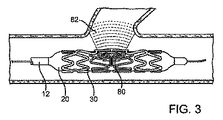
図3は、ステント30およびバルーン20の下のカテーテルのシャフト上に配置された検出機構80を使用して、側枝を識別するプロトコルを示す。オペレータは、カテーテルシャフト12を回転させて、検出機構80からフィードバックを受信する。図3に示されるように、検出機構80は、側枝小孔Oの位置を示すのを助力するために、側枝40を通過する視野82を有する画像センサーのような、センサーを備える。他の実施形態では、センサーは、側枝付近の検出ができる電気化学的センサーであり得る。センサーがバルーンの近くに配置される場合には、センサーは組織の有無を検出することができる。検出機構はカテーテル10の遠位端またはその付近で、バルーン20の内部または外部に配置され得る。
FIG. 3 shows a protocol for identifying side branches using a
別の実施形態では、カテーテルの作業端は、小型電気モーター、サーボ機構、または他の遠隔操作の駆動メカニズムのような小型の機械駆動装置によって回転可能な、個別のシャフト上に載置される。オペレータは、カテーテルの別個のシャフトを遠隔で回転させることによってカテーテルの作業端の向きを定めて、本明細書に記述されたあらゆる感覚フィードバック機構を使用して、正確な位置決めを行うことができる。あるいは、オペレータは、ジョイスティックまたはカテーテルの遠位領域に信号を送信することができる他の手動インターフェース機器を使用することによって、完全にまたは部分的に遠位部分の動作を制御することができる。 In another embodiment, the working end of the catheter is mounted on a separate shaft that can be rotated by a small mechanical drive, such as a small electric motor, servo mechanism, or other remotely operated drive mechanism. The operator can orient the working end of the catheter by remotely rotating a separate shaft of the catheter to provide accurate positioning using any sensory feedback mechanism described herein. Alternatively, the operator can fully or partially control the movement of the distal portion by using a joystick or other manual interface device that can send a signal to the distal region of the catheter.
さらに別の実施形態では、検出機構は、自動配向システム回路に連結される。本実施形態では、システムは、検出機構から送信された回転位置信号を監視するための(一般的にデジタルプロセッサを使用する)制御器を有する。前記信号は、作業端の位置が正確に定められたかどうかを判断するために使用される。適切に配置されていない場合には、適切な配向が行われるまで、自動配向システムが作業端を回転させる。本実施形態では、システムは、検出機構と制御可能な電気モーターまたはステントを適切に配向する他の位置決め器との間のフィードバックループを使用して、自己位置合わせされる。オペレータは、別のワイヤまたは機器を送達して、遠位端の位置および配向を安定させることが可能である。例えば、オペレータは、ガイドワイヤまたは光ファイバを側枝に送達して、システムの安定化、または場合によってはシステムの固定を助力することができる。 In yet another embodiment, the detection mechanism is coupled to an automatic orientation system circuit. In this embodiment, the system has a controller (typically using a digital processor) for monitoring the rotational position signal transmitted from the detection mechanism. The signal is used to determine whether the position of the working end has been accurately determined. If not properly positioned, the automatic orientation system rotates the working end until proper orientation is achieved. In this embodiment, the system is self-aligned using a feedback loop between the detection mechanism and a controllable electric motor or other positioner that properly orients the stent. The operator can deliver another wire or instrument to stabilize the position and orientation of the distal end. For example, an operator can deliver a guidewire or optical fiber to the side branch to help stabilize the system or possibly fix the system.
図4は、ステントが展開位置に達したか(緑色光)、または展開すべきでないか(赤色光)、をオペレータに通知するために、赤色光84および緑色光86(または同等の視覚的または可聴の信号)を備えたオペレータインターフェースを有する、近位カテーテルハブ16を示す。本実施例では、センサーの電源はカテーテルと一体化することが可能であり、完全なシステムを単用のシステムとすることができる。
FIG. 4 illustrates that the
一実施形態では、オペレータインターフェースおよび関連する回路網はカテーテルから分離され、複数回使用することができる。インターフェースは、ワイヤレス接続または物理的なコネクタによって、センサーまたは側枝ロケータに連結され得る。電源は、統合型(例えば、バッテリ)または外部電源とすることができる。 In one embodiment, the operator interface and associated circuitry is separated from the catheter and can be used multiple times. The interface can be coupled to the sensor or side branch locator by wireless connection or physical connector. The power source can be an integrated (eg, battery) or an external power source.
図5は、分岐領域付近の3mmの血管と関連付けたシステムのプロファイルを示す。図6は、同じ血管に対する2本ワイヤシステムの代表的なプロファイルを示す。単ワイヤシステムの利点がこれらの図に示される。図6に示されるような第二のワイヤ86(および、場合によって第二のバルーン)の必要性を削減することによって、本発明の単ワイヤシステムのプロファイルは、2本ワイヤシステムよりも20%、通常は30%、一般的には50%低減される。例えば、単ワイヤ(図5)を備えたバルーンを覆うステントの幅は、通常1.5mmを超えず、好ましくは1.4mmを超えず、しばしば、側枝部分を通る任意の貫通性部材の出口ポイントに対する遠位部分にわたって1.2mm未満である。好適な一実施形態では、冠状血管用にデザインされたとき、システムのプロファイルは約1mmである。ニューロ血管用途に対しては、システムはより小さくなり得るが、頸動脈用途に対しては、システムのプロファイルが大きくなり得る。 FIG. 5 shows the profile of the system associated with a 3 mm vessel near the bifurcation region. FIG. 6 shows a representative profile of a two wire system for the same vessel. The advantages of a single wire system are shown in these figures. By reducing the need for a second wire 86 (and possibly a second balloon) as shown in FIG. 6, the profile of the single wire system of the present invention is 20% greater than the two wire system, Usually it is reduced by 30%, typically 50%. For example, the width of a stent covering a balloon with a single wire (FIG. 5) typically does not exceed 1.5 mm, and preferably does not exceed 1.4 mm, often the exit point of any penetrating member through the side branch portion. Less than 1.2 mm over the distal portion of In one preferred embodiment, the system profile is about 1 mm when designed for coronary vessels. For neurovascular applications, the system can be smaller, but for carotid applications, the system profile can be larger.
冠状分岐に対して、機器は、通常、直径が一般的に2.5mmから5mmまでの範囲(狭窄を除いて)の血管に使用される。本発明の圧着冠状動脈分岐ステントを含む単ワイヤ分岐システムは、1.5mmよりも小さく、場合によっては1.4mmよりも小さく、一般的には1.3mmに近づけることが可能である。一部の場合には、分岐ステントおよび送達システムのプロファイルは、必要なステントのサイズおよび特定の解剖学的位置に基づいて、1.2mmに近づけられ、時にはそれ以下とすることができる。比較のために、送達システム上の従来の非分岐ステントのプロファイルは、通常1.2mmであり、一般的に1mmに近く、0.9mm未満の場合もある。 For coronary bifurcations, devices are usually used for blood vessels with diameters generally ranging from 2.5 mm to 5 mm (excluding stenosis). A single wire bifurcation system comprising a crimped coronary bifurcation stent of the present invention can be smaller than 1.5 mm, in some cases smaller than 1.4 mm, and generally closer to 1.3 mm. In some cases, the bifurcated stent and delivery system profile can approach 1.2 mm, and sometimes less, based on the required stent size and specific anatomical location. For comparison, the profile of a conventional unbranched stent on a delivery system is typically 1.2 mm, generally close to 1 mm, and may be less than 0.9 mm.
さらなる比較として、一般に使用される冠状動脈ガイドワイヤの直径は、ほぼ0.35mmである。代表的なガイドワイヤ管腔は、ID(内径)が0.43mmで、OD(外径)が0.58mmである。さらに、折り畳んだバルーンのサイズおよび圧着ステントの壁厚(通常、約0.41mm)を加えて、二重ガイドワイヤ管腔を備えた二重ガイドワイヤ機器の材料単独のスタックは、1.4mmよりも大きい。2本ワイヤシステムの実際のプロファイルは、一般的に1.5mmよりも大きく、通常は1.6mmよりも大きく、しばしば1.8mmまたはそれを超えることもある。側面部分を膨張させるために第二のバルーンが必要である場合には、システムは、上述のうちの高い範囲となり、さらに大きくなる場合がある。 As a further comparison, the diameter of a commonly used coronary guidewire is approximately 0.35 mm. A typical guidewire lumen has an ID (inner diameter) of 0.43 mm and an OD (outer diameter) of 0.58 mm. In addition, with the size of the folded balloon and the wall thickness of the crimped stent (usually about 0.41 mm), a single guide material stack of dual guidewire devices with dual guidewire lumens is better than 1.4 mm Is also big. The actual profile of a two-wire system is typically greater than 1.5 mm, usually greater than 1.6 mm, and often 1.8 mm or more. If a second balloon is required to inflate the side portion, the system can be in the higher range described above and even larger.
図7は、単一のバルーン102を用いて単一の側枝部分105を有する分岐ステント104を展開する、単ガイドワイヤの分岐ステント送達システム100を示す。送達システムの位置決めおよび配向は、予め組み込まれて側枝分岐部位SBの近くで解放され得る、突出する弾性(「ポップアップ」)マーカー106を使用して得られる。マーカーは、蛍光透視撮像下で視認される。ポップアップマーカー106は、それが血管壁に面している間は、拘束された状態を保つ。カテーテルシャフト108が回転する(矢印109)ときに、ポップアップマーカーが側枝SBの開口部(os)と位置合わせされ、側枝に入る。蛍光透視撮像下で、側枝SB内のマーカー106の出現は、配向が最適に近い状態であり、ステント104を展開できることをオペレータに示す。
FIG. 7 illustrates a single guidewire bifurcated
一実施形態では、突出するマーカーは、血管創傷を最小限に抑えるために柔軟な先端を有する。突出したマーカーは、ニッケルチタンのような超弾性または形状記憶合金、またはステンレス鋼合金、コバルトクロム合金、MP35などのような弾性金属、および他の金属で作製され得る。あるいは、突出するマーカーは、ナイロンまたはナイロン混紡、Pebax、または他の弾性、生体適合性ポリマーのようなポリマーで作製され得る。オペレータに見えるようにするために、放射線不透過性材料をマーカーに取り付けることができる。放射線不透過性の材料は、産業界で知られている他の従来の方法で、ポップアップマーカーシステム上に、圧着、成形押出または共押出、接着または配置され得る。NiTiが形状記憶状態にあるときに使用される場合には、NiTiの温度を変化させることによって、突出するマーカーが作動することができ、それによって、処理中にマーカーシステムに適用された記憶形状をとる。 In one embodiment, the protruding marker has a flexible tip to minimize vascular wounds. Protruding markers can be made of superelastic or shape memory alloys such as nickel titanium, or elastic metals such as stainless steel alloys, cobalt chromium alloys, MP35, and other metals. Alternatively, the protruding marker can be made of a polymer such as nylon or nylon blend, Pebax, or other elastic, biocompatible polymer. A radiopaque material can be attached to the marker to make it visible to the operator. The radiopaque material can be crimped, molded or co-extruded, glued or placed on the pop-up marker system in other conventional ways known in the industry. When used when NiTi is in the shape memory state, changing the temperature of NiTi can activate the protruding marker, thereby changing the memory shape applied to the marker system during processing. Take.
図8Aおよび図8Bは、側枝部分202を備えた分岐ステント200のための単一のワイヤおよび単一のバルーンを示す。本実施形態では、可動マーカー204は、管腔206、部分的な管腔、スリット、またはカテーテルのシャフト208上の1つ以上のフックまたは短管腔を通って出入りすることができる。可動マーカーアセンブリ204は、細長い部材を備え、前記部材は、好ましくは、金属ワイヤまたはリボン、ナイロンのような押出ポリマー、またはマーカーアセンブリを通路に出したり/入れたりすることができるような、必要とされる物理的特性を有する他の材料で作製される。細長い部材の遠位端210は、プラチナイリジウムまたはタングステン、MRI可視材料のようなマーカー材料、または現在産業界で使用されている他の公知のマーカー材料で作製され得る。あるいは、マーカー材料は、マーカーアセンブリの端部に取り付け、配置、接着、または連結され得る。マーカーアセンブリは、カテーテルの遠位端またはその近くで管腔206の外に押し出されたときに突出しやすいように、また、側枝SBに近接するように押された場合には側枝内に現れて、超音波、MRI、またはCTのような操作で使用される撮像システムによって視覚的に識別され得るように、折り曲げて予め形状を与えられ得る。マーカーアセンブリ204の遠位端は、血管壁を押したときに血管創傷を最小限に抑えるようにデザインされる。当該のデザインは、柔軟な先端、ポリマーの延長部、局部的ループ、または他のオプションを含むことができる。回転可能なシャフト208は、ガイドワイヤ管腔212、可動マーカー管腔206、および膨張管腔214を備えた編組シャフト部分211からなる。管腔の直径は、マーカーアセンブリの寸法に適合するように小さくすることができる。ニッケルチタンまたは鋼のリボンをアセンブリに使用した場合には、材料の厚さは、通常、0.025mmから0.25mmまでの範囲であるが、0.25mmから2.54mmまでの範囲となる場合もある。管腔は、マーカーに締まりばめできるようにデザインされ得、すなわち大きくされ得る。
8A and 8B show a single wire and a single balloon for a
上述のものは本発明の好適な実施形態の詳細であるが、種々の代替物、改良物、および同等物が使用され得る。したがって、上述の説明は、添付の請求項によって定義される本発明の範囲を限定するものであるとして解釈されるべきではない。 While the above are details of a preferred embodiment of the present invention, various alternatives, modifications, and equivalents may be used. Therefore, the above description should not be taken as limiting the scope of the invention which is defined by the appended claims.
Claims (18)
該シャフトの該ステント展開領域上に側面部分を有するステントと、
該カテーテルシャフト上の側枝センサーと、
を備える、ステント送達システム。 A catheter shaft having a stent deployment region near the distal end;
A stent having side portions on the stent deployment region of the shaft;
A side branch sensor on the catheter shaft;
A stent delivery system comprising:
該側枝部分を有する該人工器官を担送するカテーテルを提供するステップと、
該側枝部分が該側枝に隣接するまで、該カテーテルを該主管腔内に進めるステップと、
該側枝部分と該側枝血管との相対的位置を観察しつつ、該カテーテルを回転および/または軸方向に配置するステップと、
該側枝部分と該側枝血管とのアラインメントを観察するステップの後に、該人工器官を展開するステップと、
を包含する、方法。 A method for deploying a prosthesis having a side branch portion into a side branch vessel within a main lumen, comprising:
Providing a catheter for carrying the prosthesis having the side branch portion;
Advancing the catheter into the main lumen until the side branch portion is adjacent to the side branch;
Rotating and / or axially locating the catheter while observing the relative position of the side branch portion and the side branch vessel;
Deploying the prosthesis after observing the alignment between the side branch portion and the side branch vessel; and
Including the method.
Applications Claiming Priority (2)
| Application Number | Priority Date | Filing Date | Title |
|---|---|---|---|
| US68462405P | 2005-05-24 | 2005-05-24 | |
| PCT/US2006/020443 WO2006127997A2 (en) | 2005-05-24 | 2006-05-24 | Delivery system for bifurcation stents |
Publications (2)
| Publication Number | Publication Date |
|---|---|
| JP2008541882A true JP2008541882A (en) | 2008-11-27 |
| JP2008541882A5 JP2008541882A5 (en) | 2009-07-30 |
Family
ID=37452885
Family Applications (1)
| Application Number | Title | Priority Date | Filing Date |
|---|---|---|---|
| JP2008513761A Pending JP2008541882A (en) | 2005-05-24 | 2006-05-24 | Bifurcated stent delivery system |
Country Status (5)
| Country | Link |
|---|---|
| US (2) | US8608789B2 (en) |
| EP (1) | EP1883373A4 (en) |
| JP (1) | JP2008541882A (en) |
| CN (1) | CN101188984B (en) |
| WO (1) | WO2006127997A2 (en) |
Cited By (4)
| Publication number | Priority date | Publication date | Assignee | Title |
|---|---|---|---|---|
| JP2015529477A (en) * | 2012-06-28 | 2015-10-08 | コーニンクレッカ フィリップス エヌ ヴェ | Fiber optic sensor guided navigation for blood vessel visualization and monitoring |
| WO2018106040A1 (en) * | 2016-12-07 | 2018-06-14 | 재단법인 아산사회복지재단 | Intracranial pressure measuring device |
| JP2018099485A (en) * | 2016-12-22 | 2018-06-28 | テルモ株式会社 | Medical device and treatment method |
| JP2018522675A (en) * | 2015-08-03 | 2018-08-16 | メディリア アクチェンゲゼルシャフト | Sensor bend catheter |
Families Citing this family (19)
| Publication number | Priority date | Publication date | Assignee | Title |
|---|---|---|---|---|
| US9101500B2 (en) * | 2005-01-10 | 2015-08-11 | Trireme Medical, Inc. | Stent with self-deployable portion having wings of different lengths |
| CN101102728B (en) * | 2005-01-10 | 2011-06-22 | 曲利姆医疗股份有限公司 | Stand with self-deployable portion |
| US20080147174A1 (en) * | 2006-12-11 | 2008-06-19 | Trireme Medical, Inc. | Apparatus and method of using markers to position stents in bifurcations |
| EP2349440B1 (en) * | 2008-10-07 | 2019-08-21 | Mc10, Inc. | Catheter balloon having stretchable integrated circuitry and sensor array |
| US8389862B2 (en) | 2008-10-07 | 2013-03-05 | Mc10, Inc. | Extremely stretchable electronics |
| US8366763B2 (en) * | 2009-07-02 | 2013-02-05 | Tryton Medical, Inc. | Ostium support for treating vascular bifurcations |
| US9237961B2 (en) * | 2010-04-23 | 2016-01-19 | Medtronic Vascular, Inc. | Stent delivery system for detecting wall apposition of the stent during deployment |
| US20130041454A1 (en) * | 2011-02-09 | 2013-02-14 | Business Expectations Llc | Sensor Actuated Stent |
| US8998827B2 (en) | 2012-02-13 | 2015-04-07 | Intervalve, Inc. | Ellipticity measuring device |
| JP6471143B2 (en) * | 2013-03-13 | 2019-02-13 | ボストン サイエンティフィック サイムド,インコーポレイテッドBoston Scientific Scimed,Inc. | Non-migrating tissue fixation system for fully covered stents |
| US20140277365A1 (en) * | 2013-03-14 | 2014-09-18 | University Of Rochester | Ultrasound-guided endograft system |
| WO2014144070A1 (en) * | 2013-03-15 | 2014-09-18 | Hunter William L | Stent monitoring assembly and method of use thereof |
| US10709587B2 (en) * | 2013-11-05 | 2020-07-14 | Hameem Unnabi Changezi | Bifurcated stent and delivery system |
| US9974675B2 (en) * | 2014-04-04 | 2018-05-22 | W. L. Gore & Associates, Inc. | Delivery and deployment systems for bifurcated stent grafts |
| WO2015200718A1 (en) | 2014-06-25 | 2015-12-30 | Hunter William L | Devices, systems and methods for using and monitoring tubes in body passageways |
| CN105726175B (en) * | 2016-04-28 | 2019-01-08 | 张健 | A kind of main branch saccule support system of special type for bifurcated lesions interventional therapy |
| WO2020214970A1 (en) * | 2019-04-17 | 2020-10-22 | University Of Pittsburgh - Of The Commonwealth System Of Higher Education | Endovascular orifice detection for fenestrated stent graft deployment |
| CN116672571A (en) * | 2022-02-22 | 2023-09-01 | 上海科罡医疗技术有限公司 | Medical catheter |
| CN117179963A (en) * | 2022-05-30 | 2023-12-08 | 上海臻亿医疗科技有限公司 | Implant release orientation marking device, implant delivery system and method of operating the same |
Citations (4)
| Publication number | Priority date | Publication date | Assignee | Title |
|---|---|---|---|---|
| JP2003526402A (en) * | 1999-06-04 | 2003-09-09 | アドバンスド ステント テクノロジーズ, インコーポレイテッド | Catheter with secondary sheath |
| JP2003532447A (en) * | 1999-09-23 | 2003-11-05 | アドバンスド ステント テクノロジーズ, インコーポレイテッド | Stent placement area converter and method of using the same |
| US20040267352A1 (en) * | 1999-01-13 | 2004-12-30 | Davidson Charles J. | Stent with protruding branch portion for bifurcated vessels |
| US20050060027A1 (en) * | 1999-01-13 | 2005-03-17 | Advanced Stent Technologies, Inc. | Catheter balloon systems and methods |
Family Cites Families (45)
| Publication number | Priority date | Publication date | Assignee | Title |
|---|---|---|---|---|
| US4774949A (en) * | 1983-06-14 | 1988-10-04 | Fogarty Thomas J | Deflector guiding catheter |
| US4994071A (en) | 1989-05-22 | 1991-02-19 | Cordis Corporation | Bifurcating stent apparatus and method |
| US5609627A (en) | 1994-02-09 | 1997-03-11 | Boston Scientific Technology, Inc. | Method for delivering a bifurcated endoluminal prosthesis |
| US5596990A (en) * | 1995-06-06 | 1997-01-28 | Yock; Paul | Rotational correlation of intravascular ultrasound image with guide catheter position |
| US6436104B2 (en) * | 1996-01-26 | 2002-08-20 | Cordis Corporation | Bifurcated axially flexible stent |
| US5891133A (en) | 1996-03-29 | 1999-04-06 | Eclipse Surgical Technologies, Inc. | Apparatus for laser-assisted intra-coronary transmyocardial revascularization and other applications |
| UA58485C2 (en) | 1996-05-03 | 2003-08-15 | Медінол Лтд. | Method for manufacture of bifurcated stent (variants) and bifurcated stent (variants) |
| US6770092B2 (en) * | 1996-05-03 | 2004-08-03 | Medinol Ltd. | Method of delivering a bifurcated stent |
| US5749825A (en) | 1996-09-18 | 1998-05-12 | Isostent, Inc. | Means method for treatment of stenosed arterial bifurcations |
| US6599316B2 (en) | 1996-11-04 | 2003-07-29 | Advanced Stent Technologies, Inc. | Extendible stent apparatus |
| US6596020B2 (en) | 1996-11-04 | 2003-07-22 | Advanced Stent Technologies, Inc. | Method of delivering a stent with a side opening |
| ATE539702T1 (en) | 1996-11-04 | 2012-01-15 | Advanced Stent Tech Inc | DEVICE FOR EXPANDING A STENT AND METHOD FOR DEPLOYING IT |
| US7220275B2 (en) | 1996-11-04 | 2007-05-22 | Advanced Stent Technologies, Inc. | Stent with protruding branch portion for bifurcated vessels |
| US6325826B1 (en) | 1998-01-14 | 2001-12-04 | Advanced Stent Technologies, Inc. | Extendible stent apparatus |
| US6682536B2 (en) | 2000-03-22 | 2004-01-27 | Advanced Stent Technologies, Inc. | Guidewire introducer sheath |
| US8211167B2 (en) * | 1999-12-06 | 2012-07-03 | Boston Scientific Scimed, Inc. | Method of using a catheter with attached flexible side sheath |
| US6835203B1 (en) | 1996-11-04 | 2004-12-28 | Advanced Stent Technologies, Inc. | Extendible stent apparatus |
| DE29701758U1 (en) | 1997-02-01 | 1997-03-27 | Jomed Implantate Gmbh | Radially expandable stent for implantation in a body vessel, particularly in the area of a vascular branch |
| US5928248A (en) | 1997-02-14 | 1999-07-27 | Biosense, Inc. | Guided deployment of stents |
| DE29708803U1 (en) | 1997-05-17 | 1997-07-31 | Jomed Implantate Gmbh | Radially expandable stent for implantation in a body vessel in the area of a vascular branch |
| US6165195A (en) | 1997-08-13 | 2000-12-26 | Advanced Cardiovascylar Systems, Inc. | Stent and catheter assembly and method for treating bifurcations |
| US6520988B1 (en) * | 1997-09-24 | 2003-02-18 | Medtronic Ave, Inc. | Endolumenal prosthesis and method of use in bifurcation regions of body lumens |
| US6099497A (en) | 1998-03-05 | 2000-08-08 | Scimed Life Systems, Inc. | Dilatation and stent delivery system for bifurcation lesions |
| US6261273B1 (en) * | 1998-05-07 | 2001-07-17 | Carlos E. Ruiz | Access system for branched vessels amd methods of use |
| US7655030B2 (en) | 2003-07-18 | 2010-02-02 | Boston Scientific Scimed, Inc. | Catheter balloon systems and methods |
| US7387639B2 (en) | 1999-06-04 | 2008-06-17 | Advanced Stent Technologies, Inc. | Short sleeve stent delivery catheter and methods |
| US6884258B2 (en) * | 1999-06-04 | 2005-04-26 | Advanced Stent Technologies, Inc. | Bifurcation lesion stent delivery using multiple guidewires |
| EP1229859A2 (en) | 1999-09-23 | 2002-08-14 | Advanced Stent Technologies, Inc. | Bifurcation stent system and method |
| US6361555B1 (en) * | 1999-12-15 | 2002-03-26 | Advanced Cardiovascular Systems, Inc. | Stent and stent delivery assembly and method of use |
| AU3726401A (en) | 2000-02-18 | 2001-08-27 | E V R Endovascular Res Es S A | Endolumenal device for delivering and deploying an endolumenal expandable prosthesis |
| DE60141466D1 (en) * | 2000-03-30 | 2010-04-15 | Teramed Corp | BRANCHED TRANSPLANT |
| US6676691B1 (en) | 2001-03-28 | 2004-01-13 | Ayman A. Hosny | Stent delivery system |
| US6761733B2 (en) * | 2001-04-11 | 2004-07-13 | Trivascular, Inc. | Delivery system and method for bifurcated endovascular graft |
| US6749628B1 (en) | 2001-05-17 | 2004-06-15 | Advanced Cardiovascular Systems, Inc. | Stent and catheter assembly and method for treating bifurcations |
| JP4460289B2 (en) * | 2001-08-23 | 2010-05-12 | シー. ガム、ダレル | Catheter assembly |
| US7544170B2 (en) | 2002-04-25 | 2009-06-09 | Boston Scientific Scimed, Inc. | Guidewire management devices and methods |
| EP1539291A4 (en) * | 2002-09-20 | 2010-03-10 | Flowmedica Inc | Method and apparatus for selective material delivery via an intra-renal catheter |
| US7717953B2 (en) * | 2004-10-13 | 2010-05-18 | Tryton Medical, Inc. | Delivery system for placement of prosthesis at luminal OS |
| WO2005041810A2 (en) * | 2003-11-03 | 2005-05-12 | B-Balloon Ltd. | Treatment of vascular bifurcations |
| US7344557B2 (en) | 2003-11-12 | 2008-03-18 | Advanced Stent Technologies, Inc. | Catheter balloon systems and methods |
| US7766951B2 (en) * | 2004-03-04 | 2010-08-03 | Y Med, Inc. | Vessel treatment devices |
| JP5054524B2 (en) | 2004-06-08 | 2012-10-24 | アドバンスド ステント テクノロジーズ, インコーポレイテッド | Stent with protruding branch for branch pipe |
| US20060047335A1 (en) * | 2004-08-26 | 2006-03-02 | Israel Henry M | Catheter with deflector |
| US7922754B2 (en) * | 2005-04-18 | 2011-04-12 | Trireme Medical, Inc. | Apparatus and methods for delivering prostheses to luminal bifurcations |
| US8257419B2 (en) * | 2006-03-10 | 2012-09-04 | Cordis Corporation | Apparatus for treating a bifurcated region of a conduit |
-
2006
- 2006-05-23 US US11/439,707 patent/US8608789B2/en not_active Expired - Fee Related
- 2006-05-24 JP JP2008513761A patent/JP2008541882A/en active Pending
- 2006-05-24 EP EP06760425.6A patent/EP1883373A4/en not_active Withdrawn
- 2006-05-24 WO PCT/US2006/020443 patent/WO2006127997A2/en active Application Filing
- 2006-05-24 CN CN2006800180807A patent/CN101188984B/en not_active Expired - Fee Related
-
2013
- 2013-11-13 US US14/079,374 patent/US20140074215A1/en not_active Abandoned
Patent Citations (4)
| Publication number | Priority date | Publication date | Assignee | Title |
|---|---|---|---|---|
| US20040267352A1 (en) * | 1999-01-13 | 2004-12-30 | Davidson Charles J. | Stent with protruding branch portion for bifurcated vessels |
| US20050060027A1 (en) * | 1999-01-13 | 2005-03-17 | Advanced Stent Technologies, Inc. | Catheter balloon systems and methods |
| JP2003526402A (en) * | 1999-06-04 | 2003-09-09 | アドバンスド ステント テクノロジーズ, インコーポレイテッド | Catheter with secondary sheath |
| JP2003532447A (en) * | 1999-09-23 | 2003-11-05 | アドバンスド ステント テクノロジーズ, インコーポレイテッド | Stent placement area converter and method of using the same |
Cited By (5)
| Publication number | Priority date | Publication date | Assignee | Title |
|---|---|---|---|---|
| JP2015529477A (en) * | 2012-06-28 | 2015-10-08 | コーニンクレッカ フィリップス エヌ ヴェ | Fiber optic sensor guided navigation for blood vessel visualization and monitoring |
| JP2018522675A (en) * | 2015-08-03 | 2018-08-16 | メディリア アクチェンゲゼルシャフト | Sensor bend catheter |
| WO2018106040A1 (en) * | 2016-12-07 | 2018-06-14 | 재단법인 아산사회복지재단 | Intracranial pressure measuring device |
| CN110049721A (en) * | 2016-12-07 | 2019-07-23 | 财团法人峨山社会福祉财团 | Cerebral measurement device |
| JP2018099485A (en) * | 2016-12-22 | 2018-06-28 | テルモ株式会社 | Medical device and treatment method |
Also Published As
| Publication number | Publication date |
|---|---|
| CN101188984A (en) | 2008-05-28 |
| US20140074215A1 (en) | 2014-03-13 |
| WO2006127997A3 (en) | 2007-10-25 |
| EP1883373A4 (en) | 2017-03-01 |
| EP1883373A2 (en) | 2008-02-06 |
| WO2006127997A2 (en) | 2006-11-30 |
| US8608789B2 (en) | 2013-12-17 |
| CN101188984B (en) | 2012-05-30 |
| US20070016279A1 (en) | 2007-01-18 |
Similar Documents
| Publication | Publication Date | Title |
|---|---|---|
| US8608789B2 (en) | Delivery system for bifurcation stents | |
| JP5137568B2 (en) | Stent delivery device | |
| US8702744B2 (en) | Apparatus and methods for renal stenting | |
| US10098770B2 (en) | Endovascular aneurysm devices, systems, and methods | |
| JP4398090B2 (en) | Stent delivery system | |
| US8167929B2 (en) | System and method for delivering a stent to a bifurcated vessel | |
| US8608791B2 (en) | Apparatus and methods for delivering prostheses to luminal bifurcations | |
| US20070021819A1 (en) | Apparatus and Methods for Locating an Ostium of a Vessel | |
| US20050101968A1 (en) | Ostial locator device and methods for transluminal interventions | |
| JP2007504897A (en) | Medical device delivery system | |
| EP2227188B1 (en) | Stent placement system | |
| US9750921B2 (en) | Valve plane locator method and device | |
| US20120245673A1 (en) | Stent and stent delivery system for side-branch locations in a conduit | |
| WO2022245946A9 (en) | Orientable intravascular devices and methods | |
| WO2002047591A1 (en) | Side branch dilatation catheter | |
| EP2799037A2 (en) | Pusher guide wire | |
| WO2024013013A1 (en) | Catheter system and method for closure of at least one paravalvular leakage |
Legal Events
| Date | Code | Title | Description |
|---|---|---|---|
| A521 | Written amendment |
Free format text: JAPANESE INTERMEDIATE CODE: A523 Effective date: 20090525 |
|
| A621 | Written request for application examination |
Free format text: JAPANESE INTERMEDIATE CODE: A621 Effective date: 20090525 |
|
| A521 | Written amendment |
Free format text: JAPANESE INTERMEDIATE CODE: A523 Effective date: 20100519 |
|
| A131 | Notification of reasons for refusal |
Free format text: JAPANESE INTERMEDIATE CODE: A131 Effective date: 20110713 |
|
| A977 | Report on retrieval |
Free format text: JAPANESE INTERMEDIATE CODE: A971007 Effective date: 20110714 |
|
| A02 | Decision of refusal |
Free format text: JAPANESE INTERMEDIATE CODE: A02 Effective date: 20111207 |