JP5137568B2 - Stent delivery device - Google Patents
Stent delivery device Download PDFInfo
- Publication number
- JP5137568B2 JP5137568B2 JP2007501448A JP2007501448A JP5137568B2 JP 5137568 B2 JP5137568 B2 JP 5137568B2 JP 2007501448 A JP2007501448 A JP 2007501448A JP 2007501448 A JP2007501448 A JP 2007501448A JP 5137568 B2 JP5137568 B2 JP 5137568B2
- Authority
- JP
- Japan
- Prior art keywords
- balloon
- stent
- catheter system
- distal end
- catheter
- Prior art date
- Legal status (The legal status is an assumption and is not a legal conclusion. Google has not performed a legal analysis and makes no representation as to the accuracy of the status listed.)
- Expired - Fee Related
Links
Images


Classifications
-
- A—HUMAN NECESSITIES
- A61—MEDICAL OR VETERINARY SCIENCE; HYGIENE
- A61F—FILTERS IMPLANTABLE INTO BLOOD VESSELS; PROSTHESES; DEVICES PROVIDING PATENCY TO, OR PREVENTING COLLAPSING OF, TUBULAR STRUCTURES OF THE BODY, e.g. STENTS; ORTHOPAEDIC, NURSING OR CONTRACEPTIVE DEVICES; FOMENTATION; TREATMENT OR PROTECTION OF EYES OR EARS; BANDAGES, DRESSINGS OR ABSORBENT PADS; FIRST-AID KITS
- A61F2/00—Filters implantable into blood vessels; Prostheses, i.e. artificial substitutes or replacements for parts of the body; Appliances for connecting them with the body; Devices providing patency to, or preventing collapsing of, tubular structures of the body, e.g. stents
- A61F2/82—Devices providing patency to, or preventing collapsing of, tubular structures of the body, e.g. stents
- A61F2/856—Single tubular stent with a side portal passage
-
- A—HUMAN NECESSITIES
- A61—MEDICAL OR VETERINARY SCIENCE; HYGIENE
- A61F—FILTERS IMPLANTABLE INTO BLOOD VESSELS; PROSTHESES; DEVICES PROVIDING PATENCY TO, OR PREVENTING COLLAPSING OF, TUBULAR STRUCTURES OF THE BODY, e.g. STENTS; ORTHOPAEDIC, NURSING OR CONTRACEPTIVE DEVICES; FOMENTATION; TREATMENT OR PROTECTION OF EYES OR EARS; BANDAGES, DRESSINGS OR ABSORBENT PADS; FIRST-AID KITS
- A61F2/00—Filters implantable into blood vessels; Prostheses, i.e. artificial substitutes or replacements for parts of the body; Appliances for connecting them with the body; Devices providing patency to, or preventing collapsing of, tubular structures of the body, e.g. stents
- A61F2/95—Instruments specially adapted for placement or removal of stents or stent-grafts
- A61F2/954—Instruments specially adapted for placement or removal of stents or stent-grafts for placing stents or stent-grafts in a bifurcation
-
- A—HUMAN NECESSITIES
- A61—MEDICAL OR VETERINARY SCIENCE; HYGIENE
- A61F—FILTERS IMPLANTABLE INTO BLOOD VESSELS; PROSTHESES; DEVICES PROVIDING PATENCY TO, OR PREVENTING COLLAPSING OF, TUBULAR STRUCTURES OF THE BODY, e.g. STENTS; ORTHOPAEDIC, NURSING OR CONTRACEPTIVE DEVICES; FOMENTATION; TREATMENT OR PROTECTION OF EYES OR EARS; BANDAGES, DRESSINGS OR ABSORBENT PADS; FIRST-AID KITS
- A61F2/00—Filters implantable into blood vessels; Prostheses, i.e. artificial substitutes or replacements for parts of the body; Appliances for connecting them with the body; Devices providing patency to, or preventing collapsing of, tubular structures of the body, e.g. stents
- A61F2/95—Instruments specially adapted for placement or removal of stents or stent-grafts
- A61F2/958—Inflatable balloons for placing stents or stent-grafts
-
- A—HUMAN NECESSITIES
- A61—MEDICAL OR VETERINARY SCIENCE; HYGIENE
- A61F—FILTERS IMPLANTABLE INTO BLOOD VESSELS; PROSTHESES; DEVICES PROVIDING PATENCY TO, OR PREVENTING COLLAPSING OF, TUBULAR STRUCTURES OF THE BODY, e.g. STENTS; ORTHOPAEDIC, NURSING OR CONTRACEPTIVE DEVICES; FOMENTATION; TREATMENT OR PROTECTION OF EYES OR EARS; BANDAGES, DRESSINGS OR ABSORBENT PADS; FIRST-AID KITS
- A61F2/00—Filters implantable into blood vessels; Prostheses, i.e. artificial substitutes or replacements for parts of the body; Appliances for connecting them with the body; Devices providing patency to, or preventing collapsing of, tubular structures of the body, e.g. stents
- A61F2/02—Prostheses implantable into the body
- A61F2/04—Hollow or tubular parts of organs, e.g. bladders, tracheae, bronchi or bile ducts
- A61F2/06—Blood vessels
- A61F2002/065—Y-shaped blood vessels
-
- A—HUMAN NECESSITIES
- A61—MEDICAL OR VETERINARY SCIENCE; HYGIENE
- A61F—FILTERS IMPLANTABLE INTO BLOOD VESSELS; PROSTHESES; DEVICES PROVIDING PATENCY TO, OR PREVENTING COLLAPSING OF, TUBULAR STRUCTURES OF THE BODY, e.g. STENTS; ORTHOPAEDIC, NURSING OR CONTRACEPTIVE DEVICES; FOMENTATION; TREATMENT OR PROTECTION OF EYES OR EARS; BANDAGES, DRESSINGS OR ABSORBENT PADS; FIRST-AID KITS
- A61F2250/00—Special features of prostheses classified in groups A61F2/00 - A61F2/26 or A61F2/82 or A61F9/00 or A61F11/00 or subgroups thereof
- A61F2250/0014—Special features of prostheses classified in groups A61F2/00 - A61F2/26 or A61F2/82 or A61F9/00 or A61F11/00 or subgroups thereof having different values of a given property or geometrical feature, e.g. mechanical property or material property, at different locations within the same prosthesis
- A61F2250/0039—Special features of prostheses classified in groups A61F2/00 - A61F2/26 or A61F2/82 or A61F9/00 or A61F11/00 or subgroups thereof having different values of a given property or geometrical feature, e.g. mechanical property or material property, at different locations within the same prosthesis differing in diameter
-
- A—HUMAN NECESSITIES
- A61—MEDICAL OR VETERINARY SCIENCE; HYGIENE
- A61F—FILTERS IMPLANTABLE INTO BLOOD VESSELS; PROSTHESES; DEVICES PROVIDING PATENCY TO, OR PREVENTING COLLAPSING OF, TUBULAR STRUCTURES OF THE BODY, e.g. STENTS; ORTHOPAEDIC, NURSING OR CONTRACEPTIVE DEVICES; FOMENTATION; TREATMENT OR PROTECTION OF EYES OR EARS; BANDAGES, DRESSINGS OR ABSORBENT PADS; FIRST-AID KITS
- A61F2250/00—Special features of prostheses classified in groups A61F2/00 - A61F2/26 or A61F2/82 or A61F9/00 or A61F11/00 or subgroups thereof
- A61F2250/0058—Additional features; Implant or prostheses properties not otherwise provided for
- A61F2250/006—Additional features; Implant or prostheses properties not otherwise provided for modular
-
- A—HUMAN NECESSITIES
- A61—MEDICAL OR VETERINARY SCIENCE; HYGIENE
- A61M—DEVICES FOR INTRODUCING MEDIA INTO, OR ONTO, THE BODY; DEVICES FOR TRANSDUCING BODY MEDIA OR FOR TAKING MEDIA FROM THE BODY; DEVICES FOR PRODUCING OR ENDING SLEEP OR STUPOR
- A61M25/00—Catheters; Hollow probes
- A61M25/01—Introducing, guiding, advancing, emplacing or holding catheters
- A61M2025/0186—Catheters with fixed wires, i.e. so called "non-over-the-wire catheters"
-
- A—HUMAN NECESSITIES
- A61—MEDICAL OR VETERINARY SCIENCE; HYGIENE
- A61M—DEVICES FOR INTRODUCING MEDIA INTO, OR ONTO, THE BODY; DEVICES FOR TRANSDUCING BODY MEDIA OR FOR TAKING MEDIA FROM THE BODY; DEVICES FOR PRODUCING OR ENDING SLEEP OR STUPOR
- A61M25/00—Catheters; Hollow probes
- A61M25/10—Balloon catheters
- A61M2025/1043—Balloon catheters with special features or adapted for special applications
- A61M2025/1045—Balloon catheters with special features or adapted for special applications for treating bifurcations, e.g. balloons in y-configuration, separate balloons or special features of the catheter for treating bifurcations
-
- A—HUMAN NECESSITIES
- A61—MEDICAL OR VETERINARY SCIENCE; HYGIENE
- A61M—DEVICES FOR INTRODUCING MEDIA INTO, OR ONTO, THE BODY; DEVICES FOR TRANSDUCING BODY MEDIA OR FOR TAKING MEDIA FROM THE BODY; DEVICES FOR PRODUCING OR ENDING SLEEP OR STUPOR
- A61M25/00—Catheters; Hollow probes
- A61M25/10—Balloon catheters
- A61M2025/1043—Balloon catheters with special features or adapted for special applications
- A61M2025/1056—Balloon catheters with special features or adapted for special applications having guide wire lumens outside the main shaft, i.e. the guide wire lumen is within or on the surface of the balloon
-
- A—HUMAN NECESSITIES
- A61—MEDICAL OR VETERINARY SCIENCE; HYGIENE
- A61M—DEVICES FOR INTRODUCING MEDIA INTO, OR ONTO, THE BODY; DEVICES FOR TRANSDUCING BODY MEDIA OR FOR TAKING MEDIA FROM THE BODY; DEVICES FOR PRODUCING OR ENDING SLEEP OR STUPOR
- A61M25/00—Catheters; Hollow probes
- A61M25/10—Balloon catheters
- A61M25/1011—Multiple balloon catheters
Description
本発明は、ステント送達装置、方法に関し、特に、狭小であり、回転的及び並進的の両方で想定可能に配置できる能力を有するステント送達装置に関する。 The present invention relates to a stent delivery device and method, and more particularly, to a stent delivery device that is narrow and has the ability to be conceivably placed both rotationally and translationally.
従来技術として知られているステント送達装置には、いくつかの課題が関連して存在し、特に、分岐部病変の処置のための課題がある。まず、従来のステント送達装置は、外径が広く、特に、通常、2本のガイドワイヤルーメン(一つは主ガイドワイヤ用のものであり、一つは側肢ガイドワイヤ用のもの)を含んで構成されていることが知られている。現在、周知のシステムで比較的多くのものの特徴としては、所定の位置へアクセスする際に、操縦性が容易でない。更に、2本のガイドワイヤルーメンにより、頻繁にワイヤが絡み合う結果となり、何回も挿入したり戻したりすることなく、実施することが困難である。これらの装置における、その他の課題としては、血管内で適切でない配置となることである。この課題は、有効な場所に示された放射線不透過のマーカの利用で解決されている。しかしながら、実際の利用が3次元で行われるにもかかわらず、視覚化が2次元平面内で行われる。したがって、不適切な展開が通常行われてしまい、ステントジェイリングや、不十分な被覆といった結果が頻繁に起こる。 There are several problems associated with the stent delivery devices known as the prior art, particularly for the treatment of bifurcation lesions. First, conventional stent delivery devices have a wide outer diameter, and typically typically include two guidewire lumens, one for the main guidewire and one for the side limb guidewire. It is known that it is composed of Currently, a relatively large number of known systems are not easy to maneuver when accessing a predetermined location. Furthermore, the two guidewire lumens result in frequent tangling of the wires and are difficult to implement without being inserted and returned many times. Another problem with these devices is that they are not properly positioned within the blood vessel. This problem has been solved by using a radiopaque marker shown at an effective location. However, the visualization is done in a two-dimensional plane, even though the actual use is done in three dimensions. Thus, improper deployment is usually performed, often resulting in stent jaring and inadequate coverage.
先行する分岐部ステント送達システムの例としては、米国特許番号6,048,361(Von Oepen)に開示されている。システムは、放射状に増加された穴と、ステントが乗せられるバルーンカテーテルを含むステントを備え、バルーンカテーテルは、増加された穴の真中で抜け出るために、ガイドワイヤが通過する空房を備える。システムは、ガイドワイヤ用の、比較的広い外径を必要とする2つの通路を備える。加えて、2つのワイヤが。絡み合うという課題を生じる。 An example of a prior bifurcated stent delivery system is disclosed in US Pat. No. 6,048,361 (Von Oopen). The system includes a stent including a radially increased hole and a balloon catheter on which the stent is placed, and the balloon catheter includes an air chamber through which the guide wire passes to exit in the middle of the increased hole. The system comprises two passages for the guidewire that require a relatively wide outer diameter. In addition, two wires. The problem of entanglement arises.
その他の先行する分岐部ステント送達システム、方法の例としては、米国特許番号6,692,483(Vardi他)と、米国公開番号2001/0049548(Vardi他)に開示されている。これらは、主ガイドワイヤルーメンと、側肢ルーメンを有する柔軟なサイドシースとを有するカテーテルを含む。その方法は、そのガイドワイヤの一つを最初に挿入し、次に、システムを前進させ、最終的に、2番目のガイドワイヤを前進することで、ワイヤの絡み合いを減らすことが開示されている。代替的に、ガイドワイヤの一つが、システムの中に収納され、システムが定位置になったときにのみ、抜け出される。しかしながら、ワイヤの絡み合いの課題は、システムの除去の際においても発生する可能性がある。加えて、ここに開示されているシステムは、分岐部を進みすぎてしまい、最善の結果とならない傾向がある。結果として、2重ルーメンの方法は、システム全体が、比較的大きなものとなる。 Examples of other prior bifurcated stent delivery systems and methods are disclosed in US Pat. No. 6,692,483 (Vardi et al.) And US Publication No. 2001/0049548 (Vardi et al.). These include a catheter having a main guidewire lumen and a flexible side sheath with a side limb lumen. The method is disclosed to reduce wire entanglement by first inserting one of the guidewires, then advancing the system and finally advancing the second guidewire. . Alternatively, one of the guide wires is retracted only when it is housed in the system and the system is in place. However, wire entanglement challenges can also occur during system removal. In addition, the systems disclosed herein tend to go too far through the bifurcation and do not provide the best results. As a result, the double lumen method results in a relatively large overall system.
その他の先行する分岐部ステント送達システム、方法の類似した例としては、米国特許番号5,749,825(Fischell他)と、米国特許番号6,682,556(Ischinger)に開示されている。このシステムは、側肢チューブを有するバルーンカテーテルを含み、2本のガイドワイヤ(1本が主血管用で、もう1本が血管枝用)を必要とする。前述の先行技術に類似して、筐体が大きく、ワイヤの絡み合いがあり、不正確な展開が、潜在的な課題である。 Similar examples of other prior bifurcated stent delivery systems and methods are disclosed in US Pat. No. 5,749,825 (Fischell et al.) And US Pat. No. 6,682,556 (Ischinger). This system includes a balloon catheter with a side limb tube and requires two guide wires (one for the main vessel and one for the vessel branch). Similar to the prior art described above, large housings, entangled wires, and inaccurate deployment are potential challenges.
ワイヤの絡み合いを回避して、回転運動について改良された従来の装置が、米国公開番号2003/0055483(Gumm)に開示されている。Gummは、回転自在に設けられたバルーンを有するカテーテルで、更に、カテーテルバルーンに付着した側肢中空体を備える、カテーテルのアセンブリが開示されている。当該装置の特徴は、バルーンの反対側に密封された回転体を利用することである。したがって、側肢中空体、バルーン、回転体は、主ハイポチューブと比べると自由に回転できる装置として機能する。上記構成は、分岐部にて、側肢に対するステントの方向付けにおいて、より良くしたものを提供するために、不可欠なものと考えられている。しかしながら、この技術においても、システムの全体の直径が結果として大きくなる。更に、移動面において、ステントを正確な位置に配置する方法を提供していない。 A conventional device that improves on rotational motion while avoiding wire entanglement is disclosed in US Publication No. 2003/0055483 (Gumm). Gumm discloses a catheter assembly having a balloon with a rotatable balloon and further comprising a side limb hollow body attached to the catheter balloon. The device is characterized by the use of a rotating body sealed on the opposite side of the balloon. Therefore, the side limb hollow body, the balloon, and the rotating body function as a device that can freely rotate as compared with the main hypotube. The above configuration is considered indispensable to provide a better orientation of the stent relative to the side limb at the bifurcation. However, even with this technique, the overall diameter of the system results in an increase. Furthermore, it does not provide a method for placing the stent in the correct position on the moving surface.
固定ワイヤバルーンカテーテルを使うことで、単一ステント送達システムを狭小にする試みが、米国公開番号2002/0147491(Khan他)のように開示されている。その装置は、バルーンの遠心端に固定的に付着されたガイドワイヤの短い部分、又は、システムの中に延びるコアワイヤのいずれかを備えることが開示されている。これは、内部のガイドワイヤルーメンを排除することで、先行技術の装置と比べてシステムの大きさが小さい。しかしながら、このシステムは、分岐点にステントを配置することの可能性を教示、提供するものではなく、急速交換の高い能力のあるものを提供するわけではない。 Attempts to narrow the single stent delivery system by using a fixed wire balloon catheter have been disclosed as in US Publication No. 2002/0147491 (Khan et al.). The device is disclosed to comprise either a short portion of a guide wire fixedly attached to the distal end of the balloon or a core wire extending into the system. This eliminates the internal guidewire lumen, thereby reducing the size of the system compared to prior art devices. However, this system does not teach and provide the possibility of placing a stent at a bifurcation point, and does not provide a high ability for rapid exchange.
したがって、上述の制限を回避するステント送達システムに対する、幅広いニーズがあり、このようなステント送達システムを提供することは、大きな利益があると考えられる。 Accordingly, there is a broad need for a stent delivery system that circumvents the limitations described above, and providing such a stent delivery system would be of great benefit.
本発明によれば、ステント送達装置が提供される。この装置は、遠位端及び近位端を有し前記近位端が剛性体により構成されたカテーテルと、前記カテーテル上に配置された近位端、遠位端、それらに通じている膨張ルーメンを備えた固定ワイヤバルーンと、前記膨張ルーメンの中に配置され、前記剛性体の遠位端から前記バルーンの前記遠位端まで伸びており、少なくとも前記バルーンに部分的に接続されているコアワイヤと、前記バルーンに沿って配置されたガイドワイヤルーメンと、を含む。 According to the present invention, a stent delivery device is provided. The apparatus includes a catheter having a distal end and a proximal end , the proximal end being configured by a rigid body, a proximal end disposed on the catheter, a distal end , and an inflation lumen communicating therewith a fixed wire balloon having a disposed in said inflation lumen extends from the distal end of the rigid body to the distal end of the balloon, a core wire which is partially connected to at least said balloon And a guide wire lumen disposed along the balloon.
本発明によれば、ステント送達システムが提供される。このシステムは、近位端、遠位端、前記近位端及び前記遠位端を連結する筐体を有する、主血管の中を前進させるための主長型要素と、近位端及び遠位端を含む、補助血管の中を前進させるための補助長型要素と、を備える。前記補助長型要素は、部分的に前記主長型要素に付着する。システムは、クロッチポイントも含み、前記クロッチポイントでは、前記主長型要素の前記筐体が前記補助長型要素に付着しており、前記クロッチポイントの位置は、分岐部に前記システムが到達すると前記システムの前進を停止させるように構成される。 In accordance with the present invention, a stent delivery system is provided. The system includes a proximal end, a distal end, with said proximal end and housing for coupling the distal end, a main length type elements for advancing through the main vessel, a proximal end and a distal An auxiliary length element for advancing in the auxiliary vessel, including the end . The auxiliary long element partially adheres to the main long element. The system also includes a crotch point, wherein the housing of the main length type element is attached to the auxiliary length type element, and the position of the crotch point is determined when the system reaches a branching portion. Configured to stop system advancement.
本発明のさらなる側面によれば、ステント送達システムが提供され、このステント送達システムは、近位端及び遠位端を有するカテーテルと、カテーテル上に配置されたバルーンと、を含み、前記バルーンは遠位端及び近位端を有し、前記バルーンはカテーテルに対して固定されており、ステント送達システムは、更に、バルーンの遠位端に付着したワイヤと、遠位端及び近位端を有する側要素と、を含み、前記側要素は少なくとも部分的に前記バルーンに付着している。 According to a further aspect of the present invention, a stent delivery system is provided, the stent delivery system comprising a catheter having a proximal end and a distal end , and a balloon disposed on the catheter, the balloon being a distal one. has a proximal end and a proximal end, the balloon is fixed to the catheter, the side stent delivery system further comprising a wire attached to the distal end of the balloon, the distal end and a proximal end And the side element is at least partially attached to the balloon.
本発明のさらなる側面によれば、ステント送達システムが提供され、このステント送達システムは、近位端及び遠位端を有するカテーテルと、カテーテル上に配置されたバルーンと、を含み、前記バルーンは遠位端及び近位端を有し、ステント送達システムは、更に、バルーンの遠位端に付着したワイヤと、遠位端及び近位端を有する側要素と、を含み、前記側要素は少なくとも部分的に前記バルーンに付着しており、ステント送達システムは、更にクロッチポイントを含み、前記クロッチポイントの位置は、分岐部に到達したシステムの前進を停止するように構成されている。 According to a further aspect of the present invention, a stent delivery system is provided, the stent delivery system comprising a catheter having a proximal end and a distal end , and a balloon disposed on the catheter, the balloon being a distal one. having a proximal end and a proximal end, a stent delivery system further comprises a wire attached to the distal end of the balloon, and a side element having a distal end and a proximal end, wherein the side element at least in part The stent delivery system further includes a crotch point, the position of the crotch point being configured to stop the system from reaching the bifurcation.
本発明のさらなる側面によれば、ステント送達システムが提供され、このステント送達システムは、近位端及び遠位端を有するカテーテルと、カテーテルの遠位端上に配置されたバルーンとを含み、前記バルーンは遠位端及び近位端を有し、前記バルーンはカテーテルに対して固定されており、ステント送達システムは、更にステントを含み、前記ステントはバルーン上に配置され、側開口部を有し、前記側開口部は、近位端及び遠位端を有し、ステント送達システムは、更に、近位端及び遠位端を有する側肢ルーメンを含み、前記側肢ルーメンの近位端は前記バルーンの近位端に付着し、前記側肢ルーメンの遠位端は前記ステントの側開口部を通じて外に出るように構成されている。 According to a further aspect of the invention, a stent delivery system is provided, the stent delivery system comprising a catheter having a proximal end and a distal end , and a balloon disposed on the distal end of the catheter, The balloon has a distal end and a proximal end , the balloon is fixed relative to the catheter, and the stent delivery system further includes a stent, the stent being disposed on the balloon and having a side opening. The side opening has a proximal end and a distal end , and the stent delivery system further includes a side limb lumen having a proximal end and a distal end , wherein the proximal end of the side limb lumen is the Attached to the proximal end of the balloon, the distal end of the side limb lumen is configured to exit through the side opening of the stent.
本発明のさらなる側面によれば、ステント送達システムが提供される。このシステムは、近位端及び遠位端を有するカテーテルと、カテーテルの上に配置されたステントと、近位端及び遠位端を有する補助長型要素と、を含み、前記補助長型要素は、前記ステントと前記カテーテルとの間に配置され、システムは、更に、ステントの遠位端に配置されたクロッチポイントを含み、前記補助長型要素は、前記カテーテルに前記クロッチポイントで付着している。 According to a further aspect of the invention, a stent delivery system is provided. The system includes a catheter having a proximal end and a distal end , a stent disposed on the catheter, and an auxiliary elongated element having a proximal end and a distal end , the auxiliary elongated element being Disposed between the stent and the catheter, the system further including a crotch point disposed at a distal end of the stent, wherein the auxiliary elongated element is attached to the catheter at the crotch point. .
本発明のさらなる側面によれば、ステント送達システムが提供され、このステント送達システムは、近位端及び遠位端を有するカテーテルと、カテーテルの上に配置されたステントと、を含み、前記ステントは、近位端及び遠位端を有し、ステント送達システムは、更に、近位端及び遠位端を有する補助長型要素と、を含み、前記補助長型要素は前記ステントの外側に配置され、ステント送達システムは、更に、前記補助長型要素が前記カテーテルにクロッチポイントで付着していることで、前記ステントの近位端に配置されたクロッチポイントを含む。 According to a further aspect of the present invention, a stent delivery system is provided, the stent delivery system including a catheter having a proximal end and a distal end , and a stent disposed on the catheter, the stent being , has a proximal end and a distal end, the stent delivery system further comprises an auxiliary length type element having a proximal end and a distal end, wherein the auxiliary-length form element is disposed outside of the stent The stent delivery system further includes a crotch point disposed at the proximal end of the stent with the auxiliary elongated element attached to the catheter at the crotch point.
本発明のさらなる側面によれば、ステント送達システムが提供され、このステント送達システムは、近位端及び遠位端を有するカテーテルと、カテーテルの遠位端上に配置された遠位バルーンと、を含み、前記遠位バルーンは、近位端及び遠位端を有し、ステント送達システムは、更に、前記カテーテル上で、遠位バルーンの近位に配置された近位バルーンと、近位端及び遠位端を有するステントと、近位端及び遠位端を有する補助長型要素とを含み、前記補助長型要素は、前記ステントの内部に配置され、前記ステントの遠位端で抜け出ており、ステント送達システムは、更に、前記ステントの遠位端に配置されたクロッチポイントを含み、前記補助長型要素は前記クロッチポイントで前記バルーンに付着している。 According to a further aspect of the present invention, a stent delivery system is provided, the stent delivery system comprising a catheter having a proximal end and a distal end , and a distal balloon disposed on the distal end of the catheter. The distal balloon has a proximal end and a distal end , and the stent delivery system further includes a proximal balloon disposed on the catheter and proximal to the distal balloon; a proximal end; comprising: a stent having a distal end, and an auxiliary length type element having a proximal end and a distal end, said auxiliary length form element is disposed inside the stent, and exits at the distal end of the stent The stent delivery system further includes a crotch point disposed at a distal end of the stent, and the auxiliary elongated element is attached to the balloon at the crotch point.
本発明のさらなる側面によれば、カテーテルシステムが提供され、このカテーテルシステムは、遠位端、近位端、前記遠位端と前記近位端とを連結する筐体、を有するカテーテルと、遠位端、近位端、前記遠位端と前記近位端とを連結する筐体、を有する側肢ルーメンであって、前記側肢ルーメンの第1部分が前記カテーテルの前記筐体の中に配置され、前記側肢ルーメンの第2部分が前記カテーテルの前記筐体の外に配置される側肢ルーメンと、前記カテーテルの前記筐体の上に配置された出口と、を備え、前記第1部分が前記出口の近位にあり、前記第2部分が前記出口の遠位にある。 According to further aspect of the present invention, the catheter system is provided, the catheter system distal end, a proximal end, a catheter having a housing, a connecting the said proximal end and said distal end, the far proximal end, a proximal end, a side limb lumen having a housing, a connecting the said proximal end and said distal end, in a first part of the limb lumen of the casing of the catheter A side limb lumen disposed and a second portion of the side limb lumen disposed outside the housing of the catheter; and an outlet disposed on the catheter housing. A portion is proximal to the outlet and the second portion is distal to the outlet.
本発明のさらなる側面によれば、分岐部を処置する方法が提供され、この方法は、血管枝の中に側肢ガイドワイヤを導入し、主長型要素、側肢要素、クロッチポイントを含むステント送達システムであって、前記クロッチポイントの位置は、前記主長型要素と前記側肢要素とが付着するように構成され、前記クロッチポイントの位置は、前記システムが分岐部に到達したときに前進を停止するように構成され、更に、ステント送達システムは、前記主長型要素の上にステントを備えたステント送達システムを準備し、前記ステントを展開することを含む。 According to a further aspect of the present invention, a method for treating a bifurcation is provided, the method introducing a side limb guidewire into a vessel branch and comprising a main length element, a side limb element, a crotch point A delivery system, wherein the position of the crotch point is configured such that the main elongated element and the side limb element are attached, and the position of the crotch point is advanced when the system reaches a bifurcation. The stent delivery system further includes providing a stent delivery system comprising a stent over the main elongated element and deploying the stent.
本発明のさらなる側面によれば、分岐部を処置する方法が提供され、この方法は、遠位端にバルーンを有するカテーテルと、前記バルーンの遠位端に配置された固定ワイヤと、少なくとも部分的に前記カテーテルに付着した側肢ルーメンとを有するステント送達システムを準備することを含む。ここで、付着した点は、停止点を決定する。分岐部を処置する方法は、更に、クロッチポイントが分岐部に到達することで、自動的に前進が止まる位置まで、前記ステント送達システムを、主血管を通じて前進することを含む。 According to a further aspect of the present invention, there is provided a method of treating a bifurcation, the method, a catheter having a balloon at a distal end, a fixed wire disposed at a distal end of the balloon, at least partially Providing a stent delivery system having a side limb lumen attached to the catheter. Here, the adhered point determines the stop point. The method of treating the bifurcation further includes advancing the stent delivery system through the main vessel to a position where advancement automatically stops when the crotch point reaches the bifurcation.
本発明のさらなる側面によれば、直接ステントによって、血管内の病変部を処置する方法が提供される。この方法は、ステント送達システムであって、固定ワイヤバルーンを有するカテーテルと、前記バルーンに通じて配置されたコアワイヤと、少なくとも部分的に前記バルーンに沿って配置されたガイドワイヤルーメンと、前記バルーン上に配置されたステントと、を有するステント送達システムを準備し、前記血管の中に前記病変部を通じてガイドワイヤを挿入し、前記ガイドワイヤルーメンの中に前記ガイドワイヤの近位端を配置し、前記ステントが前記病変部に位置するまで、前記ステント送達システムのガイドワイヤを前進し、バルーンを膨張させ、前記ステントを展開することを含む。 According to a further aspect of the invention, a method for treating a lesion in a blood vessel with a direct stent is provided. The method includes a stent delivery system comprising a catheter having a fixed wire balloon, a core wire disposed through the balloon, a guidewire lumen disposed at least partially along the balloon, and a balloon on the balloon. A stent delivery system comprising: a stent delivery system comprising: inserting a guide wire through the lesion into the blood vessel; placing a proximal end of the guide wire into the guide wire lumen; Advancing a guidewire of the stent delivery system, inflating a balloon, and deploying the stent until the stent is located in the lesion.
本発明のさらなる側面によれば、血管内の病変部を処置する方法を提供する。本方法は、ステント送達システムを準備することを含み、前記システムは、固定ワイヤバルーンを有するカテーテルと、前記バルーンに通じて配置されたコアワイヤと、少なくとも部分的に前記バルーンに沿って配置されたガイドワイヤルーメンと、前記バルーン上に配置されたステントと、を有するステント送達システムを準備し、前記ガイドワイヤルーメンの中に前記ガイドワイヤを配置し、前記血管内を通じて前記ステント送達システムを前進し、前記ステントが前記病変部に配置されるまで、病変部を通じて、前記固定ワイヤを導入し、前記バルーンを膨張し、前記ステントを展開することを含む。 According to a further aspect of the invention, a method for treating a lesion in a blood vessel is provided. The method includes providing a stent delivery system that includes a catheter having a fixed wire balloon, a core wire disposed through the balloon, and a guide disposed at least partially along the balloon. Providing a stent delivery system having a wire lumen and a stent disposed on the balloon, disposing the guide wire within the guide wire lumen, advancing the stent delivery system through the blood vessel, and Introducing the fixation wire through the lesion, inflating the balloon, and deploying the stent until a stent is placed in the lesion.
以下に記述される発明の好適な態様における、さらなる特徴によれば、主長型要素がカテーテルであり、補助長型要素が側肢ルーメンである。好適な態様では、カテーテルはバルーンを含む。前記カテーテルは、固定ワイヤバルーンカテーテル、オーバーザワイヤカテーテル、急速交換カテーテルのいずれかであってよい。一態様では、主長型要素がカテーテルであり、補助長型要素が位置決めシステムである。位置決めシステムは少なくとも一つのストッパを含み、前記ストッパはスプリング・ワイヤーであってよく、例えば取付機構を含み、一態様として、前記取付機構がポリマジャケットであり、前記ポリマジャケットは前記スプリング・ワイヤーの近位部を定位置に保持するように構成され、前記ポリマジャケットの遠心端がクロッチポイントを決める。 According to further features in preferred embodiments of the invention described below, the main length element is a catheter and the auxiliary length element is a side limb lumen. In a preferred embodiment, the catheter includes a balloon. The catheter may be a fixed wire balloon catheter, an over-the-wire catheter, or a rapid exchange catheter. In one aspect, the primary length element is a catheter and the auxiliary length element is a positioning system. The positioning system includes at least one stopper, which may be a spring wire, for example, including an attachment mechanism, and in one aspect, the attachment mechanism is a polymer jacket, and the polymer jacket is proximate to the spring wire. The position is held in place and the distal end of the polymer jacket determines the crotch point.
一態様として、前記システムは、主長型要素上に配置された側開口部を有するステントを含み、前記クロッチポイントが、前記ステントの前記側開口部の遠位部に位置する。他の態様では、前記システムは、近位端と遠位端とを有するステントを含み、前記ステントは、主長型要素上に配置される。ここで、前記クロッチポイントは、前記ステントの近心端に配置される。更に他の態様では、前記システムは、近位端と遠位端とを有する近位ステントと、近位端と遠位端とを有する遠位ステントとを含み、前記近位ステントは、主長型要素上に配置され、前記遠位ステントは、主長型要素上の近位ステントの遠位に配置されている。この態様では、前記クロッチポイントが、前記近位ステントの遠位端に位置されてよく、2つのステントが離れて配置されてよい。態様では、前記クロッチポイントの近位にて、主長型要素、補助長型要素の筐体が付着している。好適な態様では、前記システムの外径は、1mmよりも少ない。典型的な態様では、システムの外径は、およそ0.5mmである。 In one aspect, the system includes a stent having a side opening disposed on a main elongated element, and the crotch point is located distal to the side opening of the stent. In another aspect, the system includes a stent having a proximal end and a distal end , the stent being disposed on the main elongated element. Here, the crotch point is disposed at the mesial end of the stent. In yet another aspect, the system includes a proximal stent having a proximal end and a distal end, and a distal stent having a proximal end and a distal end, said proximal stent, Omocho Located on the mold element, the distal stent is positioned distal to the proximal stent on the main length element. In this aspect, the crotch point may be located at the distal end of the proximal stent and the two stents may be spaced apart. In the aspect, the housing of the main-length element and the auxiliary-length element is attached in the vicinity of the crotch point. In a preferred embodiment, the outer diameter of the system is less than 1 mm. In a typical embodiment, the outer diameter of the system is approximately 0.5 mm.
更に、記述された好適な態様における特徴によれば、ステント送達装置は、前記側肢ルーメンの近位端が前記カテーテルの中に配置される特徴を含み、側肢ルーメンの遠位端が、カテーテルの外側に配置されたバルーンと離れている。さらなる特徴によれば、ステント送達システムは、前記バルーンの遠位端に、遠位連結要素を含む。態様において、前記遠位連結要素は、側肢ルーメンとして、前記カテーテルと同じ側に配置され、前記遠位連結要素は、前記側肢ルーメンと前記遠位連結要素との両方を通じて配置変更可能な側肢ガイドワイヤを受けるように構成される。その他の態様では、前記遠位連結要素が、側肢ルーメンとして前記カテーテルの反対側に配置され、遠位連結要素を通じて、前記ステントの外側に、配置変更可能な主ガイドワイヤを受けるように構成される。 Furthermore, according to the features in the preferred embodiments described, the stent delivery device includes the features of proximal end of the limb lumen is disposed within said catheter, the distal end of the side limb lumen, catheter Separated from the balloon placed outside. According to a further feature, the stent delivery system includes a distal coupling element at the distal end of the balloon. In an aspect, the distal connecting element is disposed as a side limb lumen on the same side as the catheter, and the distal connecting element is repositionable through both the side limb lumen and the distal connecting element. Configured to receive a limb guidewire. In another aspect, the distal connecting element is disposed on the opposite side of the catheter as a side limb lumen and is configured to receive a repositionable main guidewire through the distal connecting element to the outside of the stent. The
本発明は、狭小な筐体を有し、実質的に想定される並進的及び回転的な位置決めをするステント送達システムを提供することで、現在、知られている不十分な箇所を首尾よく解決する。 The present invention successfully resolves the currently known inadequacies by providing a stent delivery system having a narrow housing and substantially envisioned translational and rotational positioning. To do.
特段の記載がない限り、全ての技術的、科学的な用語は、本発明が属する通常の技術分野で、一般的に理解される意味と同一の意味を有する。ここで記述されていることと類似した又は同一の方法や装置は、実際に使用され又は本発明の試用に用いることが可能であり、最適な方法や装置は、以下で説明される。係争の場合には、定義を含めた特許明細書が参酌される。加えて、装置、方法、態様は一例に過ぎず、限定することを意図していない。 Unless defined otherwise, all technical and scientific terms have the same meaning as commonly understood in the ordinary technical field to which this invention belongs. Although methods and apparatus similar or identical to those described herein can be used in practice or used for trials of the present invention, the optimal method and apparatus are described below. In case of dispute, the patent specification including the definition will be considered. In addition, the apparatus, methods, and aspects are merely examples and are not intended to be limiting.
本発明は、ステント送達システム、ステントを病変部へ送達するための方法である。具体的には、本発明は、血管内のステントを回転調整、並進調整することで位置決めすることに使用される。実質的に想定される調整を可能とすることに加えて、本発明の装置とシステムは、従来のステント送達システムに比べて、小さな外径を有する。特に、本発明は、分岐部の処置に適しており、かつ、ワイヤが絡むことの可能性を減少する。 The present invention is a stent delivery system, a method for delivering a stent to a lesion. Specifically, the present invention is used for positioning a stent in a blood vessel by adjusting rotation and translation. In addition to enabling substantially envisioned adjustments, the devices and systems of the present invention have a smaller outer diameter compared to conventional stent delivery systems. In particular, the present invention is suitable for the treatment of bifurcations and reduces the possibility of tangling wires.
本発明に従ったステント送達システムの原理及び作用は、図面及び付随の記述を参照することで、よりよく理解される。 The principles and operation of a stent delivery system according to the present invention may be better understood with reference to the drawings and accompanying descriptions.
本発明の一態様を詳細に説明するにあたって、本発明は、本出願において後述する記載や、図面に図示された内容から理解される詳細な説明や、構成要素の配置により限定されずに理解される。本発明は、他の態様や、様々な方法で実施可能である。加えて、ここに使用されている表現や専門用語は、記述の目的のためであり、限定して解釈されない。 In describing one aspect of the present invention in detail, the present invention is understood without being limited by the description to be described later in this application, the detailed description understood from the contents illustrated in the drawings, and the arrangement of components. The The present invention can be implemented in other modes and in various ways. In addition, the expressions and terminology used herein are for descriptive purposes and are not to be construed as limiting.
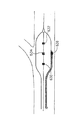
図1を参照すると、この図は、堆積したプラークを有する血管分岐部の図である。主血管1と血管枝2が、分岐点3で分岐している。プラーク4の堆積は、血管の中の任意の場所で見つけられる。図1に示すように、分岐点3に又はその近傍に、堆積したプラークが存在するならば、その場所は、ステントを正確に配置することに関して、特別な技術が必要になる。分岐部に配置されるステントは、典型的には、分岐点のやや基端の方や、やや先端の方に配置される。この結果として、ステントジェイル、不充分な被覆のいずれか一方、又は両方の状態を導く。
Referring to FIG. 1, this figure is a view of a blood vessel bifurcation having deposited plaque. The
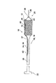
図2を参照すると、この図は、分岐部ステント送達システム5の従来技術の図である。システム5は、専用の側孔8を有するステント7を備えたカテーテル6を含む。主ガイドワイヤ9は、主血管1の中に配置され、カテーテル6の中の主ガイドワイヤルーメンを貫通している。側枝ガイドワイヤ11は、第2のガイドワイヤルーメンの中に配置され、側孔8を通過して、血管枝2の中に配置される。図1に示されるように、システム5では、配置の際に、分岐点3を進み過ぎる傾向がある。加えて、従来技術の分岐部ステントシステムは、一般的に、2つのガイドワイヤルーメン(主ガイドワイヤ9、側枝ガイドワイヤ11)の存在により直径が大きい。更に、この2つのワイヤが頻繁に、お互いに絡まり、システムの送達又は/かつ除去に失敗する。
Referring to FIG. 2, this figure is a prior art illustration of a bifurcation stent delivery system 5. The system 5 includes a
本発明は、実質的に想定される血管内での配置や調節を、並進運動及び回転運動の両方により可能にし、かつ、送達を容易にするために、狭小な筐体を保持し、ワイヤが交差することを排除することで、先行技術のシステムにおける制限を解決することを探求する。本発明の種々の異なる態様は、これより後の記述で示されるように、異なるタイプの病変の解決策を提供する。 The present invention allows a substantially envisioned placement and adjustment within the vessel by both translational and rotational movements, and retains a narrow housing to facilitate delivery, We seek to solve the limitations in prior art systems by eliminating crossing. Various different aspects of the present invention provide solutions for different types of lesions, as will be shown in the following description.
[病変タイプ1、病変タイプ2、病変タイプ4]
第1の態様として、ステント送達システム10は、図29a、29b、29dに示されているように、TYPE1(タイプ1)、TYPE2(タイプ2)又はTYPE4(タイプ4)のそれぞれに送達されるように意図されている。これらのタイプの分岐部病変において、プラーク4は、少なくとも部分的に、分岐点3の周辺の主血管の中に位置し、血管枝2の中にもまた位置する。
[
As a first aspect, the
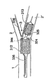
図3及び図4a〜4dを参照すると、これらの図は、各々分岐部ステント送達システム10を示し、一方がステントを有し、他方がステントを有していない図である。システム10は、主長型要素16と、主長型要素16に沿った補助長型要素34とを含む。好適な態様では、図3に示すように、補助長型要素34は、出口37の近位で主長型要素16の中に入り、出口37の遠位で、主長型要素16に沿って配置される。その他の態様では、図8を参照して説明されるように、補助長型要素34は、主長型要素16に沿って配置される。
Referring to Figures 3 and 4a-4d, these figures each show a bifurcated
好適な態様では、主長型要素16は、遠心端20及び近心端22を有するカテーテル18である。バルーン24は、カテーテル18の遠心端20に配置されている。カテーテル18は、カテーテルの近心部に沿って配置されたハイポチューブ25と、バルーン24に連通しているハイポチューブ25の中の膨張ルーメンとを含む。ハイポチューブ25は、ステンレス鋼や、剛性を担保する適切な材質から構成される。カテーテル18の遠心部に、ポリマジャケットをハイポチューブ25に置換することで、血管中における案内の融通性を向上する。上記の膨張ルーメンは、カテーテル18のポリマジャケット部を通じて、バルーン24の中まで続いている。膨張ルーメンは、バルーン24を適切な位置で膨張するために、流体、特に液体を、バルーン24の中に導くように構成されている。膨張用の端子は、従来技術で知られている配置で、近心端22に配置される。図3及び図4a〜4dに示されているカテーテル18は、商業的に利用できるバルーンカテーテルであってよい。任意的に、トルカ装置が、トルク能力を高めるために、近心端22に備えられていてもよい。そのようなトルカ装置は、従来技術として知られており、購入することができる。例えば、Qosina社(Edgewood,NY,USA,カタログパーツナンバー97333)がある。
In a preferred embodiment, the major element 16 is a
好ましい典型的な態様において、バルーン24は、固定されたワイヤバルーンであり、それ自体は、結合領域28でバルーン24の遠心端に接続された固定ワイヤ26を含む。コアワイヤ30(又は骨組み)は、バルーン24の内部に沿って配置され、カテーテル18の柔軟な部分を固くする。好適な態様において、コアワイヤ30は、固定ワイヤ26と連続的である。本発明の特に特徴的なことは、コアワイヤ30が、その近心端にてハイポチューブ25に、その遠心端にてバルーン24の遠心端に接続され、これらの間の少なくとも一つの他の場所において接続されている。再度、図4a及び図4cを参照すると、コアワイヤ30は、断面図B−Bの領域で、カテーテル18に結合され、側枝ルーメン36は、カテーテル18から抜け出る。更に、コアワイヤ30は、商業的に利用できる固定ワイヤバルーンでの長繊維と比べると、比較的、厚い。そのような長繊維は、0.005から0.009インチ(最も一般的には、0.007インチ)の範囲が典型的であるが、本発明のコアワイヤ30は、0.009から0.012インチ(最も好ましくは、0.01インチ程度)である。コアワイヤ30がカテーテル18に結合していることに加えて、この厚さは、カテーテル18の全体に沿った剛性を与える。この剛性は、カテーテル18の近心端22から遠心端20へのトルク力の伝達を行い、ポリマジャケットの屈曲やねじりによって、上記力の損失を最小にするため、トルク能力を向上したシステムを提供する。更に、コアワイヤ30による剛性や上述した特徴は、ポリマジャケット又はシステム10のその他の対応する部分により、押す力の吸収を妨げることで、本発明のシステムの押し出し能力を向上することである。
In a preferred exemplary embodiment, the
システム10は、主長型要素16の上に配置されたステント12を含み、ステント12は側開口部14を有する。ある態様では、側開口部14が、専用の側開口部であり、他の態様では、側開口部14は、ステント12のその構造の内にある、任意の開口部である。例えば、支柱がダイヤモンド型のステントは、専用の側開口部を必要としないと想定され、どんなセルも、血管枝に到達するために使用されてよい。好適な態様では、補助長型要素34は、そこを通して、側枝ガイドワイヤを配置するための側枝ルーメン36である。側枝ルーメン36は、遠心端40及び近心端42を有し、近心端42にてカテーテル18に付着され、遠心端40でカテーテル18から離れている。主長型要素及び補助長型要素が分離するポイント(この態様では、カテーテル18及び側枝ルーメン36)は、クロッチポイント44として定義される。その他の態様として、側枝ルーメン36は、クロッチポイント44の近位及び遠位の両方で、カテーテル18と離れており、クロッチポイント44でのみカテーテル18に付着している。更に、コアワイヤ30は、本処置中、蛍光により視認可能な蛍光マーカ32を含む。好適な態様では、マーカ32は、ステント12の各々の終端と、クロッチポイント44にマーカの列を形成することで、位置合わせされている。典型的に好適な態様では、付加的にマーカされる部分は、側枝ルーメン36の遠心端40を含む。この構成は、血管内のシステム10の回転調整の指標を与える。マーカの配置及び調整については、図27a〜27d、図28を参照して更に詳細に説明する。他の態様としては、システム10における重要な位置を視認可能にすると考えられる任意のマーカの配置を行うことができる。
The
クロッチポイント44は、好ましくは、側肢ルーメン36の遠心端40の近傍に位置する。図のクロッチポイントの記載は、ここに示すための目的だけであり、図示されているような実際に接続する要素を含まなくてよい。離れた部分の長さは好適には、1mmより小さい。典型的な好適な例では、離れた部分の長さは、およそ0mm(すなわち、側肢ルーメン36の遠心端40は、クロッチポイント44にある)である。この態様では、側肢ルーメン36の中のガイドワイヤは、図5を参照して、以下で述べられるように、側肢血管枝の中に入るように構成される。このガイドワイヤは、側肢ルーメン36の中に配置され、主長型要素16がクロッチポイント44を形成する。その他の態様において、離れた部分の長さは、およそ1〜5mm、更に好適には、およそ2mmである。側肢ルーメン36は、近位にかつ遠位に、必要なだけの長さであってよい。好適な態様において、クロッチポイント44の近位にある側肢ルーメン36の部分は、およそ、10〜30mmである。典型的に好適な態様では、およそ25mmである。ハイポチューブ25の少なくとも一部に沿った近位に、側肢ルーメン36を延長することで、システム10の剛性が増加する。したがって、その血管内の回転運動を容易にさせる。その他の態様において、クロッチポイント44の近位にある側肢ルーメン36の部分は、およそ、5〜15mmである。
The
A−A、B−B、C−Cの線に沿って、断面図が、図4b、4c、4dに各々描かれている。図4bに示すように、近位な場所において、側肢ルーメンカテーテル18の中に位置する。コアワイヤ30は、中心に位置し、側肢ルーメン36は、コアワイヤ30及びカテーテル18の端部の間に位置する。図4cに示すように、出口37にて、側肢ルーメン36が、カテーテル18に結合されている。図4dに示すように、出口37の遠位にて、側肢ルーメン36が外側に位置し、バルーン24に隣接する。
Along the lines AA, BB and CC, cross-sectional views are depicted in FIGS. 4b, 4c and 4d, respectively. Located in the side
次に、図5を参照するが、この図は、分岐部に配置されたシステム10の図である。クロッチポイント44は、血管内のステント12の位置決めにおいて、重要な要素である。主血管1の中のカテーテル18、及び血管枝2の中の側肢ルーメン36内にある側肢ガイドワイヤ38により、分岐点3にクロッチポイント44が達することで、システム10は、この点を越えて進むことができない。したがって、システム10は、実質的に想定されるように配置され、進みすぎることが防止される。側肢ガイドワイヤ38は、最良の剛性を有するものが選ばれる。好適な態様では、ガイドワイヤ38は、中程度の剛性を有し、システム10を案内するのに充分な剛性を有し、かつ、クロッチポイント44を越えてシステム10が進むことを妨げるのに充分な剛性を有するが、血管に穴を開けるほど強い剛性を有しない。
Reference is now made to FIG. 5, which is a diagram of the
典型的に好適な態様において、システム10を導入する方法について説明する。側肢ガイドワイヤ38は、血管枝2の中に配置される。側肢ガイドワイヤ38の近位端は、側肢ルーメン36遠位端40の中に通じる。側肢ルーメン36の中に配置された側肢ガイドワイヤ38により、システム10は、主血管1の中を前進させられる。固定ワイヤ26は、前進するときの指標となる。その他の態様において、最初に、側肢ガイドワイヤ38は用いられず、システム10は、指標としての固定ワイヤ26のみを使用して前進させられる。この態様では、側肢ガイドワイヤ38が、最初、側肢ルーメン36に積まれて、システム10が主血管1を通じて前進させられるときに、側肢ルーメン36の中に保持される。いずれの態様であっても、システム10は、絡むことの危険がなく自由に回転する。クロッチポイント44が分岐点3に達したとき、システム10の前進は、自動的に停止する。このポイントで、システム10における、血管枝2の中の側肢ガイドワイヤ38の定位置となり、かつ、ステント12の並進的、回転的に適切な位置となる。その後、バルーン24は、膨らまされ、血管内にステント12を展開する。したがって、クロッチポイント44の正確な位置が、位置決めのための正確な場所となる。展開の後に、システム10は、血管枝2から取り除かれる。記述されている本発明の特徴的な点は、必要であれば、肢ガイドワイヤ38を通じて、カテーテルを急速に交換させる機能を提供する。
In a typically preferred embodiment, a method for introducing the
本発明の特徴は、回転運動、並進運動の両方で、正確な位置決めを行うことを可能とし、更に、全体の外径が小さいことは明らかである。好適な態様では、全体の外径は、0.5〜1.5mmである。特に、側肢ルーメン36をバルーン24に、直接的に接続することで、例えば、クロッチポイント44の位置を予測可能とし、側肢ルーメン36は、並進運動する面における指標となる。固定ワイヤの使用は、トルク能力を高め、回転を容易にするが、特に、1本のみのガイドワイヤ(すなわち、肢ガイドワイヤ)にて効果がある。結合の存在、比較的厚いコアワイヤ30により、剛性、並びに、トルク及び押し出す力の伝達の容易化が提供される。側肢ルーメン36の配置は、遠心端40がその主長型要素16と離れており、すなわち、そこを通して配置されたガイドワイヤが、主長型要素16と離れており、側肢ルーメン36の血管枝2への最初の侵入を可能にする。これらの側面は、絡みを生じることなく、実質的に想定可能なシステムの回転と、実質的に想定可能な回転運動の位置決めを可能にする。
It is clear that the features of the present invention enable accurate positioning in both rotational and translational movements, and that the overall outer diameter is small. In a preferred embodiment, the overall outer diameter is 0.5 to 1.5 mm. In particular, by directly connecting the
次に、図6を参照すると、この図は、本発明の代替的な態様を示すシステム10の図である。図6に示すように、システム10は、更に、バルーン24の遠位端に接続された遠位接続要素46を含み、好適な態様では、遠位接続要素46は、バルーン24の結合領域28で接続されている。代替的な態様では、遠位接続要素46は、側肢ルーメン36の遠位のバルーン24上の任意の位置に接続される。遠心接続要素46は、システム10が分岐点3の周辺に存在するまで、側肢ガイドワイヤ38を保持するように配置される。これは、側肢ガイドワイヤ38が、システム10の送達の間、血管の中を動いてしまうことや、損傷を与えることを防止する。システム10が、分岐点3の近傍の範囲内にあるときに、側肢ガイドワイヤ38は、近位に引張られ、遠位接続要素46から離れ、血管枝2の中を前進する。その後、システム10は、クロッチポイント44まで前進し、さらなる前進を停止させ、バルーン24が膨らみ、ステント12が展開される。
Reference is now made to FIG. 6, which is a diagram of a
図8を参照すると、この図は、本発明の更に異なる態様についてのシステム10の図である。側肢ルーメン36は、外側に、主長型要素16に沿って、配置される。クロッチポイント44は、側肢ルーメン36及びバルーン24の間の接続点と近位に位置している。側肢ルーメン36の一部分は、接続点とクロッチポイント44との間にあり、バルーン24に接続されていてもよいし、離れていてもよい。
Reference is made to FIG. 8, which is a diagram of a
図9a、9bを参照すると、これらの図は、本発明の更に異なる態様についてのシステム10について、ステントとともに示した図である。この図では、側孔14が、専用の側孔ではなく、むしろ、ステント12の筐体の中にある任意の開口部である。このような種類のステントは、ここに記載されている全ての態様に適用されてよい。システム10は、固定ワイヤではなく、バルーン24の遠位端に、主ガイドワイヤ39、を含む。主ガイドワイヤルーメン50が、バルーン24の結合領域28に配置される。好適な態様では、主ガイドワイヤルーメン50は、比較的、短い(すなわち、1〜5mm)。代替的な態様では、主ガイドワイヤルーメン50は、バルーン24の側面に沿って、近位にまで延長される。好適な態様では、図9aに示すように、主ガイドワイヤ39は、主ガイドワイヤ39及び側肢ガイドワイヤ38のワイヤの交差を避けるために、ステント12の外部に位置する。代替的な態様では、図示したように、主ガイドワイヤルーメン50は、側肢ルーメン36とは逆側に配置される。
Referring to FIGS. 9a and 9b, these are views of the
図示しない、本発明の代替的な態様では、システム10は、固定ワイヤの代わりに、主ガイドワイヤルーメンを含み、更に、上述した異なる態様に対応した、クロッチポイント44を含む。
In an alternative embodiment of the present invention, not shown, the
[タイプ4A、4Bの病変]
第2の態様において、ステント送達システム110は、図29e、29fに示されるように、タイプ4A、4Bの分岐部病変に送達されるように意図されている。タイプ4Aの病変は、プラーク4が、分岐点3の近傍の、血管枝2の中に位置している。タイプ4Bの病変では、プラーク4が、主血管1の分岐点3の近位に位置する。そのような配置となる一例としては、冠動脈があり、例えば、冠動脈内にプラークが被覆することで生じる左冠動脈前下行枝(LAD)の閉塞が回避される必要がある。他の例には、腎動脈、左冠動脈主幹部、静脈グラフト等が含まれる。
[
In a second aspect,
次に、図11a〜11cを参照すると、これらの図は、タイプ4A、4Bの分岐部病変に、ステントを送達するためのシステム110であって、上述とは異なるシステム110の図である。システム110は、図11aに示すように、固定ワイヤを用いてもよいが、図11bに示されるように、オーバーザワイヤシステムであってもよいし、図11cに示されるように、急速交換システムであってもよい。
Reference is now made to FIGS. 11a-11c, which are diagrams of a
図11aを参照すると、単一のワイヤのシステムとして意図されたシステム110の図である。システム110は、主長型要素116と、補助長型要素134とを含み、好適な態様では、主長型要素116がカテーテル118である。好適な態様では、カテーテル118は、自身の遠位端に固定ワイヤ12を有するバルーン124を含む。ステント112は、バルーン124の上に配置されている。好適な態様では、補助長型要素134が、側肢ルーメン136であり、クロッチポイント144でカテーテル118に付着している。側肢ルーメン136は、近位端142及び遠位端140を有する。好適な態様では、側肢ルーメン136は、近位に、カテーテル118の中に配置され、出口137にて抜け出ており、クロッチポイント144で主長型要素116に付着されている。出口137及びクロッチポイント144の間で、側肢ルーメン136は、付着されていたり、離れていたりしてよい。好適な態様においては、側肢ルーメン136の遠心端は、クロッチポイント144にあり、そこを貫通するガイドワイヤは、停止点を示すために、遠位にまで伸びる。代替的な態様では、側肢ルーメンの遠位端が、クロッチポイント144の遠位1〜5mmに配置され、この位置でカテーテル118と離れる。
Referring to FIG. 11a, a diagram of a
代替的な態様において、側肢ルーメン136は、クロッチポイント144の近位で、カテーテル118の外部に沿って配置され、クロッチポイント144の遠位に長型要素116とは離れている。代替的な態様において、側肢ルーメン136は、クロッチポイント144の近位及び遠位の両方で、カテーテル118と離れている。クロッチポイント144は、ステント112の近位端の近くに配置される。好適な態様では、クロッチポイント144は、ステント112の遠位端の近くに配置される。
In an alternative embodiment, the
図11bを参照すると、この図は、システム110’のオーバザワイヤ、2重レールシステムを示している。システム110は、図11aに示される。システム110’は、バルーン124’の遠位端上に固定ワイヤの代わりに、主ガイドワイヤ125が存在し、カテーテル118’の長さ方向に伸びていることを除いて、図11aに示されるシステム110に類似する。主ガイドワイヤは、主血管1の中に入るように、主ガイドワイヤルーメン125を通じて配置される。システム110’は、主ガイドワイヤルーメン125の中に配置される主ガイドワイヤにより、あるいは、側肢ルーメン136’の中に配置された肢ガイドワイヤにより、定位置に導入されてよい。
Referring to FIG. 11b, this figure shows the over-the-wire, dual rail system of
図11cを参照すると、この図は、システム110’’の図であり、急速交換2重ワイヤシステムを示す。システム110’’は、固定ワイヤ、又はカテーテル118’’の長さ方向に伸びている主ガイドワイヤルーメンの代わりに、短型主ガイドワイヤルーメン127が存在し、これが出口129まで近位に伸びていることを除いて、図11a、11cに示すシステム110及び110’の両方に類似する。これらのシステムの種類は、当該技術において広く知られており、カテーテルの交換を容易にすることが知られている。本発明においては、クロッチポイント144の位置は、血管内の更に適切な場所であってよい。
Referring to FIG. 11c, this figure is an illustration of
図12を参照すると、この図は、タイプ4Bの病変のための分岐点3に配置されるシステム110の図である。側肢ガイドワイヤ138は、血管枝2の中に備えられる。システムの種類に依存して、側肢ルーメン136のクロッチポイント144が、分岐点3に着くまで、システム110は、側肢ガイドワイヤ138、固定ワイヤ126又は、主ガイドワイヤ139のどちらかに案内される。好適な態様では、遠心端140は、クロッチポイント144に存在し、ガイドワイヤ138だけが、血管枝2に入る。代替的な態様では、側肢ルーメン136は、側肢血管枝2の中で伸びる。システム110は、ゆっくりクロッチポイント144まで前進させられ、自動的にシステム110が前進を停止した後に、分岐点3に到達する。その後、バルーン124は膨らまされ、ステント112を展開し、展開の後、バルーン124が収縮させられ、システム110が取り除かれる。タイプ4Aの病変にとって、同様の方法が使用されるだろう。ここで、側肢ガイドワイヤ138は、主血管3の中に備えられよく、システム110が血管枝2の中に案内されてよい。
Referring to FIG. 12, this figure is a diagram of a
代替的な態様では、ステント送達システム210は、図13に示すように、分岐部病変に送達されるように設計され、主血管1と、この主血管1と所定の角度で結合される血管枝2とを有し、プラーク4が、血管枝2の中の分岐点3のある領域に位置する。典型的に好適な態様としては、主血管1が大動脈である。
In an alternative embodiment, the
次に、図14a、14bを参照すると、これらの図は、本発明の態様によるシステム210の外観を示す。システム210は、主長型要素216と、補助長型要素234とを含む。好適な態様では、主長型要素216は、近位端222及び遠位端220を有するカテーテル218である。カテーテル218は、遠位端220にバルーン224を備え、その上に配置されたステント212を有する。ある態様では、バルーン224は、主ガイドワイヤルーメン227を含む。代替的な態様では、第1と第2の態様を参照して記述され、少なくとも図4a、図11aに示されるように、バルーン224は、固定ワイヤバルーンである。好適な態様では、主ガイドワイヤルーメン227は、カテーテル218に沿った近位の方向に部分的に伸びて、急速な交換のための出口229を含む。代替的な態様では、システム210は、オーバーザワイヤシステムであり、主ガイドワイヤルーメン227が、カテーテル218の近心端の近位に伸びる。好適な態様では、補助長型要素234が位置決めシステム236であり、これについては、これ以降に詳細に後述される。
Reference is now made to FIGS. 14a and 14b, which illustrate the appearance of a
態様において、位置決めシステム236は、ストッパ要素250と取付機構252とを含む。好適な態様では、ストッパ要素250は、取付機構252から離れており、例えば、スプリング・ワイヤーや、フレキシブル・ポリマーや、その他任意の材料から構成されてよく、第1の状態で伸ばされて、第2の状態で折り曲げられて跳ね上がる、又はストッパとして機能する。代替的な態様では、ストッパ要素250が、取付機構252の一部分であり、第1の状態に伸ばすことが可能であり、第2の状態で、ストッパとして機能する。好適な態様では、ストッパ要素250が、形状記憶合金(例えば、ニチノール)から構成される。ここに記述した態様では、スプリング・ワイヤーが、ストッパ要素250として使用される。スプリング・ワイヤーは、伸びていない位置で、カテーテル218と実質的に水平に置かれ、とぐろ巻きになる、あるいは、ストッパから解放されたときに跳ね上がる。クロッチポイント244を形成し、取付機構252は、スプリング・ワイヤーを、主長型要素216に付着する。好適な態様では、取付機構252は、近心端256及び遠心端254を備えるジャケットである。取付機構252によって覆われるストッパ要素250の近位部は、比較的、真っ直ぐであり、ストッパ要素250の遠位部は覆われず、自由に動くことができるため、取付機構252は、少なくとも部分的にストッパ要素250(スプリング・ワイヤーとして図示されているように)を覆う。取付機構252は、生体適合性を有する任意の材料で構成してよく、好ましくは、ポリマーから構成される。好適な態様では、クロッチポイント244が、バルーン224の近心端に位置される。
In an aspect, the positioning system 236 includes a
次に、図14bを参照すると、この図は、上記態様のA−A線に沿ったシステム210の断面図である。カテーテル218は、主ガイドワイヤルーメン239を導入するための主ガイドワイヤルーメン227を備える。カテーテル218の周りに、ストッパ要素250があり、カテーテル218は、取付機構252によって適所に保持される。
Reference is now made to FIG. 14b, which is a cross-sectional view of the
次に、図15a、15bを参照すると、これらの図は、ホルダ254の中に、部分的に覆われているシステム210を示す。ホルダ254の目的は、分岐点3に到達するまで実質的に真っ直ぐな状態でストッパ要素250を、一時的に保持するためである。この態様では、ホルダ254は、取り外される(ピールアウェイ)装置である。ホルダ254は、定位置にある場合に、ストッパ要素250は、覆われており、主長型要素216の面にほぼ沿っている。図15a、15bに示す態様では、ストッパ要素250が、ステント212に沿って伸びるように、遠心方向に伸びている。クロッチポイント244の近位の領域は、図15bの断面図に示されており、カテーテル218の中の主ガイドワイヤルーメン227と、取付機構252に覆われたストッパ要素250と、取付機構252を包囲するホルダ254とを含む。
Reference is now made to FIGS. 15 a, 15 b, which show the
次に、図16a、16bを参照すると、これらの図は、本発明の他の態様に一致したホルダ254に部分的に覆われたシステム210を示す。図16a、16bに示すように、ストッパ要素250は、近位の方向に曲げられており、ストッパ要素250を取り囲み、それらを定位置に保持するホルダ254が示されている。クロッチポイント244の近位の領域では、図16bの断面図に示されているように、カテーテル218の中に主ガイドワイヤルーメン227と、取付機構252の内部及び外部の両方に覆われたストッパ要素250と、取付機構252及びストッパ要素250を取り囲むホルダ254と、を含む。
Reference is now made to FIGS. 16a and 16b, which illustrate a
次に、図17を参照すると、この図は、ガイドカテーテル260の中のシステム210を示す。ガイドカテーテル260は、システム210が導入される近心端262と、血管に通じた遠位端264と、を含む。ストッパ要素250が、ガイドカテーテル260の中に定位置のままに保持されるため、システム210は、ガイドカテーテル260の近心端262に案内されて、ホルダ254が取り除かれる。好適な態様では、ホルダ254は、取り外し可能なシステム(ピールアウェイシステム)であり、システム210がガイドカテーテル260の中に導入されている間に、外壁が取り外され、システムから排除されてよい。この場合は、その筐体の外にまで実行される。代替的な態様では、ホルダ254が鞘のような覆い形状であり、システム210がガイドカテーテル260へと導入されるときに、ホルダ254を引き戻すことが可能である。ホルダ254は、システム210がガイドカテーテル260の中にある間、ストッパ要素250を定位置に保持するための任意の装置であってよい。
Referring now to FIG. 17, this figure shows the
次に、図18a、18bを参照すると、この図は、本発明の態様による分岐部に用いられるシステム210を導入するための方法を示す。中に配置されたシステム210を備えるガイドカテーテル260が、主血管1の中を通して、分岐点3まで導入される。ガイドカテーテル260の遠位端264は、例えば、蛍光性のマーカのような、現在、知られている技術で、視覚化されている。ガイドカテーテル260の遠位端264は、血管枝2の入口であり、システム210は、図18aに示されるように、ガイドカテーテル260の遠位端264を通じて前進させられる。システム210が前進させられると、ストッパ250が、ガイドカテーテル260によって、もはや定位置を保持できなくなり、図18bに示すように、ストッパ250は、第2の状態となり、跳ね上がり、渦を巻き、ストッパとして機能する。その後、システム210は、図18cに示すように、ストッパ要素250がシステム210を更に前進することを防止するまで、前進する。このポイントで、システム210は、適切な位置となり、ステント212が展開される。
Reference is now made to FIGS. 18a and 18b, which illustrate a method for introducing a
[Y字型分岐部]
その他の態様としては、図19に示すように、Y字型の状態を有する分岐部3に送達されるよう意図されたステント送達システム310である。主血管1は、2つの分岐血管;第1血管枝2及び第2血管枝2’、に枝分かれしている。そして、プラーク4が、分岐点3の領域の主血管及び/又は血管枝の中に位置する。
[Y-shaped branch]
Another aspect is a
図20を参照すると、この図は、本発明の態様に一致した、ステント送達システム310の図である。システム310は、主長型要素316と補助長型要素334とを含む。好適な態様では、主長型要素316は、カテーテル318である。カテーテル318は、近位端322と遠位端320とを有する。近位端322は、2つを膨張するためのYバルブを有するハブ321を備える。遠位端320は、2つのバルーン;近位バルーン324及び遠位バルーン325、を有する。近位バルーン324及び遠位バルーン325の各々は、各々自身の膨張通路により、流動物が通過するように連通している。外部膨張通路335は、近位バルーン324に連通しており、内部膨張通路327が遠位バルーン325に連通している。外部膨張通路335は、内部膨張通路327と同軸上になっている。代替的に、外部膨張通路335及び内部膨張通路327は、並んで配置される。他の例では、バルーン324、325は、別々に膨張してもよい。代替的な態様では、外部膨張通路は遠位バルーン325に連通しており、内部膨張通路327は近位バルーン324に連通している。好適な態様では、遠位バルーン325が、その遠位端に固定ワイヤ326を有する。代替的な態様では、システム310が、主ガイドワイヤルーメン又は、図6に示される遠位接続要素50のような短型外部ガイドワイヤルーメンを含む。
Reference is made to FIG. 20, which is an illustration of a
好適な態様では、補助長型要素334が、近位端342と遠位端340とを有する側肢ルーメン336である。好適な態様では、側肢ルーメン336は、カテーテル318の内部に位置し、出口337で、そこから外に出る。出口337とは遠位に、側肢ルーメン336は、近位バルーン324に隣接され、クロッチポイント344まで、付着されている。代替的な態様では、側肢ルーメン336は、近位バルーン324に沿って横たわって配置されている。
In a preferred embodiment, the auxiliary elongated element 334 is a
次に、図21を参照すると、この図は、システム310にステントを備えた図である。好適な態様では、図示されているように、2つのステントが含まれる。近位ステント312が、近位バルーン324上に配置され、遠位ステント313が、遠位バルーン325上に配置される。各々のステントは、対応したバルーンを膨らませることで、別々に展開されてよい。側肢ルーメン336の遠位端が近位ステント312の遠心端とほぼ並ぶように、近位ステント312が配置される。側肢ルーメン336及びステント312の遠位の端が、クロッチポイント344を形成する。代替的な態様では、側肢ルーメン336が、クロッチポイント344を通り越して伸びる。本出願で先に記述された態様の全てが、更に、ここで適用されてよい。
Reference is now made to FIG. 21, which shows the
代替的な態様では、システム310が、その適用に応じて、1,2つのステントを含む、又はステントを全く含まない。例えば、システム310は、近位バルーン324の上のステントのみにより、プレディラテーション(predilatation)のために使用されてよい。代替的に、テーパ管が、2つの異なるステントサイズを必要としてよく、所定のサイズのステントは遠位バルーン325上に配置され、異なるサイズの他のステントは近位バルーン324に配置される。
In alternative aspects,
次に、図22a〜22dを参照すると、これらの図は、Y字型分岐部の中にシステム310を展開する方法を示す。第1に、側肢ガイドワイヤ38が第1血管枝2に導入される。そして、側肢ガイドワイヤ338の近位端が、側肢ルーメン336の遠位端を通じて、配置される。システム310は、主血管1及び第2血管枝2’を通じて、側肢ガイドワイヤ38上を前進させられる。クロッチポイント344が、分岐点3に到達した場合に、システム310は、前進することができず、システム310は、図22aに示すように定位置となる。図22bに示すように、遠位バルーン325は、内部膨張通路327を通じて膨張され、血管枝の中の遠位ステント313を、分岐点3から少し離れたところで、血管枝内で展開する。代替的な方法は、図22cに示され、近位ステント312が最初に展開され、その後、遠位ステント313が展開される。代替的な態様では、両方のステントが、同時に展開されてよい。ステントの両方が展開され定位置にある最終的な結果は、図22dに示される。
Reference is now made to FIGS. 22a-22d, which illustrate how the
次に、図23を参照すると、この図は、本発明の代替的な態様であるテーパードバルーンシステム410を示す。上述の態様に類似して、テーパードバルーンシステム410は、主長型部及び補助長型要素434を含む。好適な態様では、補助長型要素434が、側肢ルーメンである。バルーンは、近位及び遠位に所定の外径を有し、遠位の外径は近位の外径とは異なる。好適な態様では、遠位の外径は、近位の外形よりも小さく、その逆であってもよい。この種類のバルーンシステムは、血管の遠位部の中でステントの過度膨張を回避するために、血管の中にテーパードステントを導入する場合に、便利であるだろう。
Reference is now made to FIG. 23, which illustrates a tapered
[タイプ3の病変]
他の態様として、ステント送達システム510は、図29cに示されたTYPE3(タイプ3)の分岐部病変に送達されることを意図している。タイプ3の病変において、プラーク4が、分岐点3の位置の近位の主血管1に位置している。ステント送達システム510は、同様に以下で説明するように、分岐のない血管にも、送達される場合にも適用される。
[
As another aspect, the
次に、図24a〜24cを参照すると、これらの図は、タイプ3の分岐部病変へステントを送達するシステム510の態様を示す。システム510は、図24aに示されるように、固定ワイヤを用いてもよく、図24bに示されているように、オーバーザワイヤシステムに、又は、図24cに示されるように、急速交換システムに適用されてよい。
Reference is now made to FIGS. 24a-24c, which illustrate aspects of a
次に、図24aを参照すると、この図は、単一ワイヤシステムに適用されたシステム510を示す。システム510は、主長型要素516と、補助長型要素534とを含む。好適な態様では、主長型要素516がカテーテル518である。好適な態様では、カテーテル518が、遠心端に固定ワイヤ526を備えるバルーン524を含む。ステント512は、バルーン524の上に配置される。好適な態様では、補助長型要素534が、ガイドワイヤルーメン536であり、補助長型要素534は、クロッチポイント544にて、カテーテル518に付着されている。ガイドワイヤルーメン536は、近位端542と遠位端540とを有する。クロッチポイント544は、遠位端540に位置される。好適な態様では、ガイドワイヤルーメン536が、近位にカテーテル518の中に配置され、出口537にて抜け出ており、ガイドワイヤルーメン536は、クロッチポイント544で主長型要素516に付着されている。好適な態様においては、ガイドワイヤルーメン536の遠心端は、クロッチポイント544にあり、そこを貫通するガイドワイヤは、停止点を示すために、遠位にまで伸びる。代替的な態様では、ガイドワイヤルーメンの遠心端が、クロッチポイント544の遠位1〜5mmに配置され、この位置でカテーテル118と離れる。
Reference is now made to FIG. 24a, which shows a
ある態様において、ガイドワイヤルーメン536は、クロッチポイント544の近位で、カテーテル118の外部に沿って配置され、クロッチポイント144の遠位にて長型要素116と離れている。代替的な態様において、ガイドワイヤルーメン536は、クロッチポイント544の近位及び遠位の両方で、カテーテル118と離れている。クロッチポイント544は、ステント512の近位端の近くに配置される。好適な態様では、クロッチポイント544は、ステント512の遠心端の近く、およそ2〜3mmに配置される。
In certain aspects, the
好ましい典型的な態様において、図27aを参照すると、バルーン524は、固定されたワイヤバルーンであり、それ自体は、結合領域528でバルーン524の遠位端に接続された固定ワイヤ526を含む。コアワイヤ530(又は骨組み)は、バルーン524の内部に沿って配置され、カテーテル518の柔軟な部分を固くする。コアワイヤ530は、固定ワイヤ526と連続的である。本発明の特に特徴的なことは、コアワイヤ530が、その近位端にてハイポチューブ525に接続され、その遠位端にてバルーン524の遠心端に接続され、これらの間の少なくとも一つの他の場所において接続されている。特に、コアワイヤ530は、カテーテル518と結合している。更に、コアワイヤ530は、商業的に利用できる固定ワイヤバルーンでの長繊維と比べると、比較的、厚い。そのような長繊維は、0.005から0.009インチ(最も一般的には、0.007インチ)の範囲が典型的であるが、本発明のコアワイヤ530は、0.009から0.012インチ(最も好ましくは、0.01インチ程度)である。コアワイヤ30がカテーテル18に結合していることに加えて、この厚さは、カテーテル518の全体に沿った剛性を与える。この剛性は、カテーテル518の近位端522から遠位端520へのトルク力の伝達を行い、トルク能力を向上したシステムを提供する。更に、コアワイヤ530による剛性や上述した特徴は、ポリマジャケット又はシステム510のその他の対応する部分により、押す力の吸収を妨げることで、本発明のシステムの押し出し能力を向上することである。
In a preferred exemplary embodiment, referring to FIG. 27 a, the
次に、図24bを参照すると、この図は、システム510’のオーバザワイヤ、2重レールシステムを示している。システム510’は、バルーン524’の遠位端上に固定ワイヤの代わりに、ガイドワイヤ525が存在し、カテーテル518’の長さ方向に伸びている点を除いて、図25aに示されるシステム510に類似している。主ガイドワイヤは、主血管1の中に入るために、主ガイドワイヤルーメン525を通じて配置される。システム510’は、主ガイドワイヤルーメン525の中に配置される主ガイドワイヤにより、あるいは、側肢ルーメン536’の中に配置された肢ガイドワイヤにより、病変部に導入されてよい。
Reference is now made to FIG. 24b, which shows the over-the-wire, dual rail system of
次に、図24cを参照すると、この図は、急速交換2重ワイヤシステムを示す。システム510’’は、固定ワイヤ、又はカテーテル518’’の長さ方向に伸びている主ガイドワイヤルーメンの代わりに、短型主ガイドワイヤルーメン527が存在し、これが出口529まで近位に伸びていることを除いて、図24a、24cに示すシステム510及び510’の両方に類似する。本発明においては、クロッチポイント544の位置は、血管内の更に適切な場所であってよい。
Reference is now made to FIG. 24c, which shows a rapid exchange double wire system. The
次に、図26を参照すると、この図は、血管600の中の非分岐部病変に配置されたシステム510を示す。ある態様では、ガイドワイヤ610が、血管600の中に病変部を通じて導入される。システム510は、ガイドワイヤ610及び固定ワイヤ526により、その病変部分にカテーテル518が到達するまで、案内させられる。位置は、マーカ532により決定され、図27a〜27d、図28にて、更に詳細に説明される。次に、バルーン524が膨らまされ、ステント512を展開する。展開の後に、バルーン524は収縮し、システム510が取り除かれる。カテーテル518の近心端の近位に、出口を有する血管内のガイドワイヤを準備することで、カテーテルの急速交換が必要な場合に可能となる。更に、システムは、プレディラテーション(predilatation)の必要がなく、直接ステント処置に使用され、その処置の侵襲性を減少する。代替的な態様では、ガイドワイヤ610がバックロードされ、ガイドワイヤルーメン536の中に格納され、システム510が、固定ワイヤ526によって案内されて血管に導入される。システム510は、コアワイヤ530による剛性によって、病変部を通り抜けるのに適当である。システム510が所定位置にあると、ガイドワイヤ610は、バックアップワイヤが、病変部の遠位にあるために、(例えば、急速交換の機能のために)前進させられる。次に、バルーン524は膨らまされ、ステント512を展開する。通常の非分岐部ステント送達システムとして、現在利用可能な典型的な送達システム以上の、システム510を使用するいくつかのメリットがある。急速交換は、送達を容易にすることや、必要であればカテーテルの入れ替えを容易にすることを含めた、所定のメリットがあることが広く知られている。しかしながら、これにより、比較的厚いコアワイヤが、全体の直径を増加せずに、大幅な回転運動を容易にし、大幅なトルク力の伝達を促進することで、システムの送達にメリットを与える。更に、直接ステント処置において、ガイドワイヤ610又は固定ワイヤ526が、その病変部を通り抜けるために適当である。固定ワイヤ526により病変部を通り抜けることで、ステント512は自動的に配置される。
Next, referring to FIG. 26, this figure shows the
図27a〜27dを参照すると、これらの図は、好適な態様によるマーカの状態を示す。図27aに示すように、第1のマーカ630と、第2のマーカ632と、第3のマーカ634とが、コアワイヤ30上に存在し、それぞれ、ステント12の近心端、遠心端、クロッチポイント44の位置に一致して直線状に配置されている。第4のマーカ636は、クロッチポイント44に配置されるように、第1、第2のマーカ630、632とともに、三角形を形成する。図27bに示すように、システム10が定位置にあるときに、3つのマーカの相対位置は、元の状態と一致する。すなわち、第1、第2、第3のマーカ630、632、634は、直線状に配置され、第4のマーカ636が、その列から離れている。図27cに示すように、システム10が90度回転された場合には、4つのマーカ全てが比較的、同じラインに並ぶ。図27dに示すように、システム10が、180度回転されると、4番目のマーカ636は、第1、第2、第3のマーカ630、632、634の先の位置と反対側に配置される。この方法で、2次元的な視覚画面上に、システム10の回転調整を視覚化することが可能である。加えて、マーカ634及び/又は636が、三角形で配置されたり、形を示して配置されたりしてよく、図28に示すように、分岐のアクセスの方を示してよい。これは、更に、適切な位置決めのための、付加的な確認方法を提示する。したがって、全てのマーカが、互いに適切な位置であり、マーカで形成された形が分岐の方を示す場合に、分岐部にて適切な配置となっていることが確認される。
Referring to FIGS. 27a-27d, these figures show the state of the marker according to the preferred embodiment. As shown in FIG. 27a, a
本発明は、本発明の特定の態様により記載されているにもかかわらず、多くの変形例、変更態様及びバリエーションが当業者にとって適用できることが明白である。例えば、自己膨張型のステントが、バルーンで膨張可能なステントの代わりに使用されることが可能である。その場合には、カテーテルが必ずしもバルーンカテーテルである必要はない。したがって、本発明は、全ての、このような変形、修正、バリエーション(添付の特許請求の範囲と解釈の範囲で)を含むことを意図する。本明細書を参照することで、この明細書において言及される全ての刊行物、特許及び特許出願の全てが含まれる。この範囲とは、刊行物、特許、特許出願の各々の記述により、ここに含まれると、具体的に、かつ、個別に、あたかも示されているような内容と同様の範囲である。加えて、本出願の任意の参考文献の引用又は相違点の説明は、そのような参考文献が、従来技術として本発明に適用可能であることを了承しているとは解釈されない。 It will be apparent that many variations, modifications and variations are applicable to those skilled in the art, although the invention has been described in terms of particular embodiments of the invention. For example, a self-expanding stent can be used in place of a balloon expandable stent. In that case, the catheter need not necessarily be a balloon catheter. Accordingly, the present invention is intended to embrace all such alterations, modifications and variations (within the scope of the appended claims and interpretation). Reference to this specification includes all publications, patents, and patent applications mentioned in this specification. This range is the same as the contents shown as if they were specifically and individually included in the descriptions of publications, patents and patent applications. In addition, citation or explanation of differences of any reference in this application shall not be construed as an admission that such reference is applicable to the present invention as prior art.
ここで、添付した図面に関して記述された発明は、一例として示したに過ぎない。図面を参照することで、示されている詳細な部分は、一例を示し、好適な態様の説明の目的のためだけであり、最も有用である、かつ、本発明の原理、概念の側面から、迅速に理解できると信じられていることを提供するための結果として、示されていることを強調する。この点に関して、本発明の基本的な理解のために必要であること以上に詳細に、本発明の構造的な詳細を示すものでなはく、図面とともに把握できる記載から、それらの技術において明らかにされる本発明のいくつかの態様が実際に実施される。 Here, the invention described with reference to the accompanying drawings is merely an example. Referring to the drawings, the detailed portions shown are exemplary and are for the purpose of illustrating the preferred embodiments only, and are most useful and in terms of the principles, concepts of the invention, Emphasize what is shown as a result of providing what is believed to be quickly understandable. In this regard, it is not necessary to show the structural details of the present invention in more detail than is necessary for a basic understanding of the present invention. Several embodiments of the present invention are actually implemented.
Claims (20)
遠位端(20)及び近位端(25)を有し、前記近位端が剛性体(25)により構成された主長型要素(16)と、
前記主長型要素上に配置され、近位端及び遠位端と、それらに通じている膨張ルーメンとを備えた固定ワイヤバルーン(24)と、を備え、前記固定ワイヤバルーンは、前記バルーン(24)の前記遠位端に取り付けられた固定ワイヤ(26)を備え、前記固定ワイヤは、血管を通して前記カテーテルシステムを案内するように構成されており、
前記膨張ルーメンの中に配置され、前記剛性体の遠位端から、前記バルーンの前記遠位端まで伸びており、少なくとも部分的に前記主長型要素(16)に付着されたコアワイヤ(30)と、
少なくとも部分的に前記バルーンに沿って配置されると共に少なくとも部分的に前記主長型要素の中に配置された補助長型要素(34)とを備え、
前記バルーン(24)上に配置され、遠位端及び近位端を有するステントと、前記ステントの前記近位端に配置されたクロッチポイントと、を更に備え、前記補助長型要素(34)は、前記クロッチポイントで前記主長型要素に付着されるものであり、
前記補助長型要素(34)は、少なくとも1つのストッパと、付着メカニズムとを備える位置決めシステムであり、
前記位置決めシステムは、前記ステントの近傍において当該ステントに対して近位側のカテーテルシステム上に配置されている、カテーテルシステム。A catheter system,
A main elongated element (16) having a distal end (20) and a proximal end (25), said proximal end being constituted by a rigid body (25);
A fixed wire balloon (24) disposed on the main elongated element and having a proximal end and a distal end and an inflation lumen communicating therewith, the fixed wire balloon comprising the balloon ( 24) comprising a fixation wire (26) attached to the distal end of the catheter, the fixation wire being configured to guide the catheter system through a blood vessel;
A core wire (30) disposed in the inflation lumen and extending from the distal end of the rigid body to the distal end of the balloon and attached at least partially to the main elongated element (16) When,
An auxiliary elongated element (34) disposed at least partially along the balloon and at least partially disposed within the major elongated element ;
A stent disposed on the balloon (24) and having a distal end and a proximal end; and a crotch point disposed on the proximal end of the stent, wherein the auxiliary elongated element (34) comprises: , Attached to the main length element at the crotch point,
The auxiliary elongated element (34) is a positioning system comprising at least one stopper and an attachment mechanism;
The catheter system, wherein the positioning system is disposed on a catheter system proximal to the stent in the vicinity of the stent .
前記バルーン上に配置され、遠位端及び近位端を有するステントを更に備え、前記補助長型要素は、前記ステントと前記バルーンとの間に配置され、
前記ステントの前記遠位端に配置されたクロッチポイントを更に備え、前記補助長型要素は、前記クロッチポイントで前記主長型要素に付着されているカテーテルシステム。The catheter system according to claim 1,
Further comprising a stent disposed on the balloon and having a distal end and a proximal end, wherein the auxiliary elongated element is disposed between the stent and the balloon;
A catheter system further comprising a crotch point disposed at the distal end of the stent, wherein the auxiliary length element is attached to the main length element at the crotch point.
Applications Claiming Priority (5)
| Application Number | Priority Date | Filing Date | Title |
|---|---|---|---|
| US54955404P | 2004-03-04 | 2004-03-04 | |
| US60/549,554 | 2004-03-04 | ||
| US10/899,034 US20050209673A1 (en) | 2004-03-04 | 2004-07-27 | Bifurcation stent delivery devices |
| US10/899,034 | 2004-07-27 | ||
| PCT/IL2005/000258 WO2005084130A2 (en) | 2004-03-04 | 2005-03-03 | Stent delivery devices |
Publications (3)
| Publication Number | Publication Date |
|---|---|
| JP2007526073A JP2007526073A (en) | 2007-09-13 |
| JP2007526073A5 JP2007526073A5 (en) | 2008-04-17 |
| JP5137568B2 true JP5137568B2 (en) | 2013-02-06 |
Family
ID=34922716
Family Applications (1)
| Application Number | Title | Priority Date | Filing Date |
|---|---|---|---|
| JP2007501448A Expired - Fee Related JP5137568B2 (en) | 2004-03-04 | 2005-03-03 | Stent delivery device |
Country Status (5)
| Country | Link |
|---|---|
| US (2) | US20050209673A1 (en) |
| EP (2) | EP1732636A4 (en) |
| JP (1) | JP5137568B2 (en) |
| CN (2) | CN1972728B (en) |
| WO (1) | WO2005084130A2 (en) |
Cited By (3)
| Publication number | Priority date | Publication date | Assignee | Title |
|---|---|---|---|---|
| US8486025B2 (en) | 2006-05-11 | 2013-07-16 | Ronald J. Solar | Systems and methods for treating a vessel using focused force |
| US9050437B2 (en) | 2004-03-04 | 2015-06-09 | YMED, Inc. | Positioning device for ostial lesions |
| US9504473B2 (en) | 2004-03-04 | 2016-11-29 | Y Med Inc. | Vessel treatment devices |
Families Citing this family (119)
| Publication number | Priority date | Publication date | Assignee | Title |
|---|---|---|---|---|
| US7341598B2 (en) | 1999-01-13 | 2008-03-11 | Boston Scientific Scimed, Inc. | Stent with protruding branch portion for bifurcated vessels |
| US6325826B1 (en) * | 1998-01-14 | 2001-12-04 | Advanced Stent Technologies, Inc. | Extendible stent apparatus |
| US6835203B1 (en) | 1996-11-04 | 2004-12-28 | Advanced Stent Technologies, Inc. | Extendible stent apparatus |
| EP0944366B1 (en) * | 1996-11-04 | 2006-09-13 | Advanced Stent Technologies, Inc. | Extendible double stent |
| US6599316B2 (en) | 1996-11-04 | 2003-07-29 | Advanced Stent Technologies, Inc. | Extendible stent apparatus |
| US8257425B2 (en) | 1999-01-13 | 2012-09-04 | Boston Scientific Scimed, Inc. | Stent with protruding branch portion for bifurcated vessels |
| US20040097996A1 (en) | 1999-10-05 | 2004-05-20 | Omnisonics Medical Technologies, Inc. | Apparatus and method of removing occlusions using an ultrasonic medical device operating in a transverse mode |
| WO2002067653A2 (en) | 2001-02-26 | 2002-09-06 | Scimed Life Systems, Inc. | Bifurcated stent and delivery system |
| US8425549B2 (en) | 2002-07-23 | 2013-04-23 | Reverse Medical Corporation | Systems and methods for removing obstructive matter from body lumens and treating vascular defects |
| KR100893070B1 (en) * | 2002-09-19 | 2009-04-17 | 엘지전자 주식회사 | Method and apparatus for providing and receiving multicast service in a radio communication system |
| US8298280B2 (en) | 2003-08-21 | 2012-10-30 | Boston Scientific Scimed, Inc. | Stent with protruding branch portion for bifurcated vessels |
| US7794414B2 (en) | 2004-02-09 | 2010-09-14 | Emigrant Bank, N.A. | Apparatus and method for an ultrasonic medical device operating in torsional and transverse modes |
| US7766951B2 (en) | 2004-03-04 | 2010-08-03 | Y Med, Inc. | Vessel treatment devices |
| US20080228146A1 (en) * | 2007-03-13 | 2008-09-18 | Yoav Shaked | Positioning device for ostial lesions |
| US8007528B2 (en) | 2004-03-17 | 2011-08-30 | Boston Scientific Scimed, Inc. | Bifurcated stent |
| EP1753369B1 (en) | 2004-06-08 | 2013-05-29 | Advanced Stent Technologies, Inc. | Stent with protruding branch portion for bifurcated vessels |
| US9427340B2 (en) | 2004-12-14 | 2016-08-30 | Boston Scientific Scimed, Inc. | Stent with protruding branch portion for bifurcated vessels |
| US7862601B2 (en) * | 2005-05-23 | 2011-01-04 | Incept Llc | Apparatus and methods for delivering a stent into an ostium |
| US9034025B2 (en) | 2005-05-23 | 2015-05-19 | Ostial Corporation | Balloon catheters and methods for use |
| US8317855B2 (en) | 2005-05-26 | 2012-11-27 | Boston Scientific Scimed, Inc. | Crimpable and expandable side branch cell |
| US8480728B2 (en) | 2005-05-26 | 2013-07-09 | Boston Scientific Scimed, Inc. | Stent side branch deployment initiation geometry |
| WO2007022411A1 (en) * | 2005-08-18 | 2007-02-22 | Cappella Inc. | Delivery system and method of use for positioning of a device in a bifurcation |
| US8043366B2 (en) | 2005-09-08 | 2011-10-25 | Boston Scientific Scimed, Inc. | Overlapping stent |
| US8038706B2 (en) | 2005-09-08 | 2011-10-18 | Boston Scientific Scimed, Inc. | Crown stent assembly |
| US7731741B2 (en) * | 2005-09-08 | 2010-06-08 | Boston Scientific Scimed, Inc. | Inflatable bifurcation stent |
| CA2626697A1 (en) * | 2005-09-30 | 2007-04-05 | Incept, Llc | Apparatus for locating an ostium of a vessel |
| JP2009509622A (en) * | 2005-10-03 | 2009-03-12 | ワイ メッド インク | Vascular treatment device |
| US20070112418A1 (en) | 2005-11-14 | 2007-05-17 | Boston Scientific Scimed, Inc. | Stent with spiral side-branch support designs |
| US20070118200A1 (en) * | 2005-11-18 | 2007-05-24 | Boston Scientific Scimed, Inc. | Bifurcation stent delivery system |
| US20070129750A1 (en) * | 2005-12-05 | 2007-06-07 | Abbott Laboratories | Catheter balloon device with internal guidewire lumen and method of formation |
| US8343211B2 (en) | 2005-12-14 | 2013-01-01 | Boston Scientific Scimed, Inc. | Connectors for bifurcated stent |
| US8435284B2 (en) | 2005-12-14 | 2013-05-07 | Boston Scientific Scimed, Inc. | Telescoping bifurcated stent |
| US7540881B2 (en) | 2005-12-22 | 2009-06-02 | Boston Scientific Scimed, Inc. | Bifurcation stent pattern |
| US8821561B2 (en) | 2006-02-22 | 2014-09-02 | Boston Scientific Scimed, Inc. | Marker arrangement for bifurcation catheter |
| US7833264B2 (en) | 2006-03-06 | 2010-11-16 | Boston Scientific Scimed, Inc. | Bifurcated stent |
| US20070208415A1 (en) * | 2006-03-06 | 2007-09-06 | Kevin Grotheim | Bifurcated stent with controlled drug delivery |
| US8298278B2 (en) | 2006-03-07 | 2012-10-30 | Boston Scientific Scimed, Inc. | Bifurcated stent with improvement securement |
| US8167929B2 (en) * | 2006-03-09 | 2012-05-01 | Abbott Laboratories | System and method for delivering a stent to a bifurcated vessel |
| EP2004270B1 (en) * | 2006-03-14 | 2016-11-02 | Thermopeutix Inc. | Aneurysm coil delivery system |
| US9757260B2 (en) * | 2006-03-30 | 2017-09-12 | Medtronic Vascular, Inc. | Prosthesis with guide lumen |
| US20070239252A1 (en) * | 2006-04-10 | 2007-10-11 | Medtronic Vascular, Inc. | A Mechanism to Ensure Placement of Ostial Renal Stents |
| GB2437058A (en) * | 2006-04-12 | 2007-10-17 | Vortex Innovations Ltd | Kit for endovascular repair |
| US7901378B2 (en) | 2006-05-11 | 2011-03-08 | Y-Med, Inc. | Systems and methods for treating a vessel using focused force |
| EP2051673A2 (en) | 2006-06-23 | 2009-04-29 | Boston Scientific Limited | Bifurcated stent with twisted hinges |
| US8911406B2 (en) * | 2006-07-12 | 2014-12-16 | Kensey Nash Corporation | Guide wire exchange catheter system |
| EP2061402A2 (en) * | 2006-08-18 | 2009-05-27 | Abbott Laboratories | Bifurcation stent delivery catheter and method |
| US8216267B2 (en) | 2006-09-12 | 2012-07-10 | Boston Scientific Scimed, Inc. | Multilayer balloon for bifurcated stent delivery and methods of making and using the same |
| US8608790B2 (en) * | 2006-10-06 | 2013-12-17 | Boston Scientific Scimed, Inc. | Bifurcation catheter and method |
| US7951191B2 (en) | 2006-10-10 | 2011-05-31 | Boston Scientific Scimed, Inc. | Bifurcated stent with entire circumferential petal |
| US7871396B2 (en) * | 2006-10-30 | 2011-01-18 | Boston Scientific Scimed, Inc. | Bifurcation catheter assembly and method |
| US8206429B2 (en) | 2006-11-02 | 2012-06-26 | Boston Scientific Scimed, Inc. | Adjustable bifurcation catheter incorporating electroactive polymer and methods of making and using the same |
| US7963960B2 (en) | 2006-11-07 | 2011-06-21 | Medtronic Vascular, Inc. | Cutting radio frequency catheter for creating fenestrations in graft cloth |
| US7842082B2 (en) | 2006-11-16 | 2010-11-30 | Boston Scientific Scimed, Inc. | Bifurcated stent |
| US7959668B2 (en) * | 2007-01-16 | 2011-06-14 | Boston Scientific Scimed, Inc. | Bifurcated stent |
| US8118861B2 (en) | 2007-03-28 | 2012-02-21 | Boston Scientific Scimed, Inc. | Bifurcation stent and balloon assemblies |
| US8647376B2 (en) | 2007-03-30 | 2014-02-11 | Boston Scientific Scimed, Inc. | Balloon fold design for deployment of bifurcated stent petal architecture |
| US9358142B2 (en) * | 2007-04-24 | 2016-06-07 | W. L. Gore & Associates, Inc. | Catheter having guidewire channel |
| US7959669B2 (en) | 2007-09-12 | 2011-06-14 | Boston Scientific Scimed, Inc. | Bifurcated stent with open ended side branch support |
| EP2209446A1 (en) * | 2007-10-11 | 2010-07-28 | Boston Scientific Limited | Bifurcation catheter and method |
| US9198687B2 (en) | 2007-10-17 | 2015-12-01 | Covidien Lp | Acute stroke revascularization/recanalization systems processes and products thereby |
| US8088140B2 (en) | 2008-05-19 | 2012-01-03 | Mindframe, Inc. | Blood flow restorative and embolus removal methods |
| US8066757B2 (en) | 2007-10-17 | 2011-11-29 | Mindframe, Inc. | Blood flow restoration and thrombus management methods |
| US8585713B2 (en) | 2007-10-17 | 2013-11-19 | Covidien Lp | Expandable tip assembly for thrombus management |
| US8926680B2 (en) | 2007-11-12 | 2015-01-06 | Covidien Lp | Aneurysm neck bridging processes with revascularization systems methods and products thereby |
| US10123803B2 (en) | 2007-10-17 | 2018-11-13 | Covidien Lp | Methods of managing neurovascular obstructions |
| US11337714B2 (en) | 2007-10-17 | 2022-05-24 | Covidien Lp | Restoring blood flow and clot removal during acute ischemic stroke |
| US9220522B2 (en) | 2007-10-17 | 2015-12-29 | Covidien Lp | Embolus removal systems with baskets |
| GB0721459D0 (en) * | 2007-11-01 | 2007-12-12 | Vascutek Ltd | Apparatus and method |
| US7833266B2 (en) | 2007-11-28 | 2010-11-16 | Boston Scientific Scimed, Inc. | Bifurcated stent with drug wells for specific ostial, carina, and side branch treatment |
| US8277501B2 (en) | 2007-12-21 | 2012-10-02 | Boston Scientific Scimed, Inc. | Bi-stable bifurcated stent petal geometry |
| US8747456B2 (en) | 2007-12-31 | 2014-06-10 | Boston Scientific Scimed, Inc. | Bifurcation stent delivery system and methods |
| AU2009217354B2 (en) | 2008-02-22 | 2013-10-10 | Covidien Lp | Methods and apparatus for flow restoration |
| CN101977650A (en) | 2008-04-11 | 2011-02-16 | 曼德弗雷姆公司 | Monorail neuro-microcatheter for delivery of medical devices to treat stroke, processes and products thereby |
| US8932340B2 (en) | 2008-05-29 | 2015-01-13 | Boston Scientific Scimed, Inc. | Bifurcated stent and delivery system |
| US8377108B2 (en) * | 2008-06-02 | 2013-02-19 | Boston Scientific Scimed, Inc. | Staggered two balloon bifurcation catheter assembly and methods |
| US9402754B2 (en) | 2010-05-18 | 2016-08-02 | Abbott Cardiovascular Systems, Inc. | Expandable endoprostheses, systems, and methods for treating a bifurcated lumen |
| US9545323B2 (en) | 2010-11-16 | 2017-01-17 | W. L. Gore & Associates, Inc. | Fenestration devices, systems, and methods |
| EP2703037B1 (en) * | 2011-06-16 | 2016-04-27 | Olympus Corporation | Intracorporeal insertion instrument |
| EP2739217B1 (en) | 2011-08-05 | 2022-07-20 | Route 92 Medical, Inc. | Systems for treatment of acute ischemic stroke |
| US8574283B1 (en) | 2011-08-30 | 2013-11-05 | Suraj Govind Kamat | Deployment of stents within bifurcated vessels |
| JP6103721B2 (en) * | 2012-03-26 | 2017-03-29 | テルモ株式会社 | Balloon catheter |
| EP3127497B1 (en) * | 2013-11-07 | 2018-01-31 | Cook Medical Technologies LLC | Balloon catheter with lithotripsy amplification system |
| US10285720B2 (en) | 2014-03-11 | 2019-05-14 | Neuravi Limited | Clot retrieval system for removing occlusive clot from a blood vessel |
| US9820761B2 (en) | 2014-03-21 | 2017-11-21 | Route 92 Medical, Inc. | Rapid aspiration thrombectomy system and method |
| EP3154452A1 (en) | 2014-06-13 | 2017-04-19 | Neuravi Limited | Devices for removal of acute blockages from blood vessels |
| US10265086B2 (en) | 2014-06-30 | 2019-04-23 | Neuravi Limited | System for removing a clot from a blood vessel |
| ES2770321T3 (en) | 2015-02-04 | 2020-07-01 | Route 92 Medical Inc | Rapid Aspiration Thrombectomy System |
| WO2017019563A1 (en) | 2015-07-24 | 2017-02-02 | Route 92 Medical, Inc. | Anchoring delivery system and methods |
| WO2017019564A1 (en) * | 2015-07-24 | 2017-02-02 | Route 92 Medical, Inc. | Methods of intracerebral implant delivery |
| US9937333B2 (en) * | 2015-09-01 | 2018-04-10 | Thomas Ischinger | Balloon catheter for treatment of a vessel at a bifurcation |
| CN105853035B (en) * | 2016-04-28 | 2018-11-16 | 南京医科大学第一附属医院 | A kind of main side branch saccule support system of special type for bifurcated lesions interventional therapy |
| CN105726175B (en) * | 2016-04-28 | 2019-01-08 | 张健 | A kind of main branch saccule support system of special type for bifurcated lesions interventional therapy |
| CN105769401A (en) * | 2016-04-28 | 2016-07-20 | 南京医科大学第附属医院 | Special-shaped side branch balloon stent system for bifurcation lesion interventional therapy |
| CN107349037B (en) * | 2016-05-05 | 2023-10-13 | 中国人民解放军第二军医大学 | Main and auxiliary pancreatic duct combined bracket |
| CN105726179B (en) * | 2016-05-16 | 2019-02-15 | 张健 | A kind of double saccule support systems of special type side branch for bifurcated lesions interventional therapy |
| CN105999520A (en) * | 2016-06-29 | 2016-10-12 | 青岛大学附属医院 | Sacculus lung pushing device indwelt in pleural cavity through percutaneous puncture |
| US11547415B2 (en) | 2016-07-22 | 2023-01-10 | Route 92 Medical, Inc. | Endovascular interventions in neurovascular anatomy |
| CN106236340B (en) * | 2016-08-17 | 2018-11-23 | 苗立夫 | A kind of loading can withdraw branch's protection intravascular stent system of conduit |
| KR102457315B1 (en) * | 2016-08-17 | 2022-10-24 | 뉴라비 리미티드 | A thrombus recovery system to remove an occlusive thrombus from a blood vessel |
| KR102520161B1 (en) * | 2016-12-16 | 2023-04-07 | 씨. 알. 바드, 인크. | Balloon catheter and its method |
| BE1024922B1 (en) | 2017-01-19 | 2018-08-22 | Omer Faruk Eker | SYSTEM FOR ESTABLISHING A BIFURKETED STENT |
| CN107374699A (en) * | 2017-09-05 | 2017-11-24 | 湖南瑞康通科技发展有限公司 | A kind of stent conveying device and its application method |
| CN108542552A (en) * | 2018-03-08 | 2018-09-18 | 广西中医药大学第附属医院 | Intravascular stent and its application method |
| CN109498849B (en) * | 2018-06-25 | 2020-04-24 | 北京百利康生化有限公司 | Medical fallopian tube support device |
| CN109172076A (en) * | 2018-08-02 | 2019-01-11 | 郑州大学第附属医院 | Multi-cavity air flue radiography wire catheter for conveying Y type airway stent is set with |
| US10813780B2 (en) * | 2018-08-08 | 2020-10-27 | DePuy Synthes Products, Inc. | Intraluminal implant delivery system and method |
| ES2910600T3 (en) | 2019-03-04 | 2022-05-12 | Neuravi Ltd | Powered Clot Recovery Catheter |
| CN110478601B (en) * | 2019-08-28 | 2022-06-07 | 赛诺神畅医疗科技有限公司 | Balloon catheter |
| JP2021041169A (en) | 2019-09-11 | 2021-03-18 | ニューラヴィ・リミテッド | Expandable mouth catheter |
| US11839725B2 (en) | 2019-11-27 | 2023-12-12 | Neuravi Limited | Clot retrieval device with outer sheath and inner catheter |
| US11779364B2 (en) | 2019-11-27 | 2023-10-10 | Neuravi Limited | Actuated expandable mouth thrombectomy catheter |
| US11617857B2 (en) | 2020-01-30 | 2023-04-04 | Medtronic Vascular, Inc. | Endovascular catheter with internal balloon |
| EP3858298B1 (en) | 2020-01-31 | 2024-02-28 | Bentley InnoMed GmbH | Bifurcated balloon expandable stent assembly |
| US11944327B2 (en) | 2020-03-05 | 2024-04-02 | Neuravi Limited | Expandable mouth aspirating clot retrieval catheter |
| US11633198B2 (en) | 2020-03-05 | 2023-04-25 | Neuravi Limited | Catheter proximal joint |
| US11883043B2 (en) | 2020-03-31 | 2024-01-30 | DePuy Synthes Products, Inc. | Catheter funnel extension |
| US11759217B2 (en) | 2020-04-07 | 2023-09-19 | Neuravi Limited | Catheter tubular support |
| US11872354B2 (en) | 2021-02-24 | 2024-01-16 | Neuravi Limited | Flexible catheter shaft frame with seam |
| US11937839B2 (en) | 2021-09-28 | 2024-03-26 | Neuravi Limited | Catheter with electrically actuated expandable mouth |
Family Cites Families (35)
| Publication number | Priority date | Publication date | Assignee | Title |
|---|---|---|---|---|
| US4958634A (en) * | 1987-05-06 | 1990-09-25 | Jang G David | Limacon geometry balloon angioplasty catheter systems and method of making same |
| US4983167A (en) * | 1988-11-23 | 1991-01-08 | Harvinder Sahota | Balloon catheters |
| US5439446A (en) * | 1994-06-30 | 1995-08-08 | Boston Scientific Corporation | Stent and therapeutic delivery system |
| EP0476807A1 (en) * | 1990-09-17 | 1992-03-25 | C.R. Bard, Inc. | Core wire steerable catheters |
| EP0479730B1 (en) * | 1990-10-04 | 1995-04-19 | Schneider (Europe) Ag | Balloon dilatation catheter |
| DE69121178T2 (en) * | 1990-12-21 | 1997-03-06 | Advanced Cardiovascular System | Fixed wire dilatation catheter with rotatable balloon arrangement |
| US5197978B1 (en) * | 1991-04-26 | 1996-05-28 | Advanced Coronary Tech | Removable heat-recoverable tissue supporting device |
| US5263932A (en) * | 1992-04-09 | 1993-11-23 | Jang G David | Bailout catheter for fixed wire angioplasty |
| US5549553A (en) * | 1993-04-29 | 1996-08-27 | Scimed Life Systems, Inc. | Dilation ballon for a single operator exchange intravascular catheter or similar device |
| US6440097B1 (en) * | 1995-10-06 | 2002-08-27 | Target Therapeutics, Inc. | Balloon catheter with delivery side holes |
| US6770092B2 (en) * | 1996-05-03 | 2004-08-03 | Medinol Ltd. | Method of delivering a bifurcated stent |
| US7238197B2 (en) * | 2000-05-30 | 2007-07-03 | Devax, Inc. | Endoprosthesis deployment system for treating vascular bifurcations |
| US5749825A (en) * | 1996-09-18 | 1998-05-12 | Isostent, Inc. | Means method for treatment of stenosed arterial bifurcations |
| US7591846B2 (en) * | 1996-11-04 | 2009-09-22 | Boston Scientific Scimed, Inc. | Methods for deploying stents in bifurcations |
| US6692483B2 (en) * | 1996-11-04 | 2004-02-17 | Advanced Stent Technologies, Inc. | Catheter with attached flexible side sheath |
| US6554795B2 (en) * | 1997-03-06 | 2003-04-29 | Medtronic Ave, Inc. | Balloon catheter and method of manufacture |
| DE29708803U1 (en) * | 1997-05-17 | 1997-07-31 | Jomed Implantate Gmbh | Radially expandable stent for implantation in a body vessel in the area of a vascular branch |
| EP0891751A1 (en) * | 1997-07-18 | 1999-01-20 | Thomas Prof. Dr. Ischinger | Vascular stent for bifurcations, sidebranches and ostial lesions and an application catheter and method for implantation |
| US6165195A (en) * | 1997-08-13 | 2000-12-26 | Advanced Cardiovascylar Systems, Inc. | Stent and catheter assembly and method for treating bifurcations |
| US6290673B1 (en) * | 1999-05-20 | 2001-09-18 | Conor Medsystems, Inc. | Expandable medical device delivery system and method |
| US6884258B2 (en) * | 1999-06-04 | 2005-04-26 | Advanced Stent Technologies, Inc. | Bifurcation lesion stent delivery using multiple guidewires |
| US6440161B1 (en) * | 1999-07-07 | 2002-08-27 | Endologix, Inc. | Dual wire placement catheter |
| US6375660B1 (en) * | 1999-11-22 | 2002-04-23 | Cordis Corporation | Stent delivery system with a fixed guide wire |
| US6936065B2 (en) * | 1999-11-22 | 2005-08-30 | Cordis Corporation | Stent delivery system having a fixed guidewire |
| DK1255506T3 (en) * | 2000-02-18 | 2004-01-05 | E V R Endovascular Res Es S A | Endolumenal device for delivering and placing an endolumenal expandable prosthesis |
| US6736827B1 (en) * | 2000-10-13 | 2004-05-18 | Medtronic Ave, Inc. | Low profile catheter |
| US6544219B2 (en) * | 2000-12-15 | 2003-04-08 | Advanced Cardiovascular Systems, Inc. | Catheter for placement of therapeutic devices at the ostium of a bifurcation of a body lumen |
| US20020091434A1 (en) * | 2001-01-05 | 2002-07-11 | Chambers Jeffrey W. | Apparatus and method to position a stent |
| US20040138734A1 (en) * | 2001-04-11 | 2004-07-15 | Trivascular, Inc. | Delivery system and method for bifurcated graft |
| US20030191436A1 (en) * | 2002-04-05 | 2003-10-09 | Horvers Ronald Adrianus Maria | Balloon catheter |
| US7563270B2 (en) * | 2001-08-23 | 2009-07-21 | Gumm Darrel C | Rotating stent delivery system for side branch access and protection and method of using same |
| IL151484A (en) * | 2001-08-27 | 2009-09-01 | Medinol Ltd | Single operator stenting system |
| US7273491B2 (en) * | 2002-05-30 | 2007-09-25 | Cordis Corporation | Means and method for treating an intimal dissection after stent implantation |
| US6761734B2 (en) * | 2002-07-22 | 2004-07-13 | William S. Suhr | Segmented balloon catheter for stenting bifurcation lesions |
| US7314480B2 (en) * | 2003-02-27 | 2008-01-01 | Boston Scientific Scimed, Inc. | Rotating balloon expandable sheath bifurcation delivery |
-
2004
- 2004-07-27 US US10/899,034 patent/US20050209673A1/en not_active Abandoned
-
2005
- 2005-03-03 CN CN2005800111427A patent/CN1972728B/en not_active Expired - Fee Related
- 2005-03-03 CN CN2010102667581A patent/CN101912322B/en not_active Expired - Fee Related
- 2005-03-03 US US11/070,294 patent/US7438720B2/en active Active
- 2005-03-03 EP EP05709151A patent/EP1732636A4/en not_active Withdrawn
- 2005-03-03 WO PCT/IL2005/000258 patent/WO2005084130A2/en active Application Filing
- 2005-03-03 JP JP2007501448A patent/JP5137568B2/en not_active Expired - Fee Related
- 2005-03-03 EP EP11193219.0A patent/EP2431069B1/en active Active
Cited By (3)
| Publication number | Priority date | Publication date | Assignee | Title |
|---|---|---|---|---|
| US9050437B2 (en) | 2004-03-04 | 2015-06-09 | YMED, Inc. | Positioning device for ostial lesions |
| US9504473B2 (en) | 2004-03-04 | 2016-11-29 | Y Med Inc. | Vessel treatment devices |
| US8486025B2 (en) | 2006-05-11 | 2013-07-16 | Ronald J. Solar | Systems and methods for treating a vessel using focused force |
Also Published As
| Publication number | Publication date |
|---|---|
| EP1732636A2 (en) | 2006-12-20 |
| EP2431069B1 (en) | 2019-10-16 |
| EP1732636A4 (en) | 2009-08-12 |
| WO2005084130A2 (en) | 2005-09-15 |
| US7438720B2 (en) | 2008-10-21 |
| CN101912322B (en) | 2011-12-14 |
| WO2005084130A3 (en) | 2006-03-02 |
| CN1972728A (en) | 2007-05-30 |
| CN1972728B (en) | 2010-09-15 |
| CN101912322A (en) | 2010-12-15 |
| US20050209673A1 (en) | 2005-09-22 |
| US20050209677A1 (en) | 2005-09-22 |
| EP2431069A1 (en) | 2012-03-21 |
| JP2007526073A (en) | 2007-09-13 |
Similar Documents
| Publication | Publication Date | Title |
|---|---|---|
| JP5137568B2 (en) | Stent delivery device | |
| US10028748B2 (en) | Vessel treatment devices | |
| US7766951B2 (en) | Vessel treatment devices | |
| US7753951B2 (en) | Vessel treatment devices | |
| US10022524B2 (en) | Positioning device for ostial lesions | |
| JP4416976B2 (en) | Catheter with secondary sheath | |
| US7922754B2 (en) | Apparatus and methods for delivering prostheses to luminal bifurcations | |
| JP2009509622A (en) | Vascular treatment device | |
| JP2008541882A (en) | Bifurcated stent delivery system | |
| JP2003532437A (en) | Stretchable stent device | |
| EP2227188B1 (en) | Stent placement system | |
| EP3344324B1 (en) | Balloon catheter for treatment of a vessel at a bifurcation | |
| US20210259860A1 (en) | Orientable intravascular devices and methods | |
| CN117412720A (en) | Orientable intravascular devices and methods | |
| CN116546943A (en) | Orientable intravascular devices and methods | |
| EP4240280A1 (en) | Orientable intravascular devices and methods | |
| CN114206228A (en) | Orientable intracranial occlusion device and method |
Legal Events
| Date | Code | Title | Description |
|---|---|---|---|
| A521 | Written amendment |
Free format text: JAPANESE INTERMEDIATE CODE: A523 Effective date: 20080228 |
|
| A621 | Written request for application examination |
Free format text: JAPANESE INTERMEDIATE CODE: A621 Effective date: 20080228 |
|
| RD02 | Notification of acceptance of power of attorney |
Free format text: JAPANESE INTERMEDIATE CODE: A7422 Effective date: 20100303 |
|
| RD03 | Notification of appointment of power of attorney |
Free format text: JAPANESE INTERMEDIATE CODE: A7423 Effective date: 20100303 |
|
| RD04 | Notification of resignation of power of attorney |
Free format text: JAPANESE INTERMEDIATE CODE: A7424 Effective date: 20100308 |
|
| A521 | Written amendment |
Free format text: JAPANESE INTERMEDIATE CODE: A821 Effective date: 20100303 |
|
| A131 | Notification of reasons for refusal |
Free format text: JAPANESE INTERMEDIATE CODE: A131 Effective date: 20100621 |
|
| A521 | Written amendment |
Free format text: JAPANESE INTERMEDIATE CODE: A523 Effective date: 20100921 |
|
| A131 | Notification of reasons for refusal |
Free format text: JAPANESE INTERMEDIATE CODE: A131 Effective date: 20110404 |
|
| RD03 | Notification of appointment of power of attorney |
Free format text: JAPANESE INTERMEDIATE CODE: A7423 Effective date: 20110524 |
|
| RD04 | Notification of resignation of power of attorney |
Free format text: JAPANESE INTERMEDIATE CODE: A7424 Effective date: 20110524 |
|
| A521 | Written amendment |
Free format text: JAPANESE INTERMEDIATE CODE: A523 Effective date: 20110704 |
|
| A131 | Notification of reasons for refusal |
Free format text: JAPANESE INTERMEDIATE CODE: A131 Effective date: 20120202 |
|
| A521 | Written amendment |
Free format text: JAPANESE INTERMEDIATE CODE: A523 Effective date: 20120502 |
|
| TRDD | Decision of grant or rejection written | ||
| A01 | Written decision to grant a patent or to grant a registration (utility model) |
Free format text: JAPANESE INTERMEDIATE CODE: A01 Effective date: 20121022 |
|
| A01 | Written decision to grant a patent or to grant a registration (utility model) |
Free format text: JAPANESE INTERMEDIATE CODE: A01 |
|
| A61 | First payment of annual fees (during grant procedure) |
Free format text: JAPANESE INTERMEDIATE CODE: A61 Effective date: 20121113 |
|
| R150 | Certificate of patent or registration of utility model |
Ref document number: 5137568 Country of ref document: JP Free format text: JAPANESE INTERMEDIATE CODE: R150 Free format text: JAPANESE INTERMEDIATE CODE: R150 |
|
| FPAY | Renewal fee payment (event date is renewal date of database) |
Free format text: PAYMENT UNTIL: 20151122 Year of fee payment: 3 |
|
| R250 | Receipt of annual fees |
Free format text: JAPANESE INTERMEDIATE CODE: R250 |
|
| R250 | Receipt of annual fees |
Free format text: JAPANESE INTERMEDIATE CODE: R250 |
|
| R250 | Receipt of annual fees |
Free format text: JAPANESE INTERMEDIATE CODE: R250 |
|
| R250 | Receipt of annual fees |
Free format text: JAPANESE INTERMEDIATE CODE: R250 |
|
| R250 | Receipt of annual fees |
Free format text: JAPANESE INTERMEDIATE CODE: R250 |
|
| LAPS | Cancellation because of no payment of annual fees |