JP2008533295A - Use to infiltrate copper alloys and their powder metal parts - Google Patents
Use to infiltrate copper alloys and their powder metal parts Download PDFInfo
- Publication number
- JP2008533295A JP2008533295A JP2007555176A JP2007555176A JP2008533295A JP 2008533295 A JP2008533295 A JP 2008533295A JP 2007555176 A JP2007555176 A JP 2007555176A JP 2007555176 A JP2007555176 A JP 2007555176A JP 2008533295 A JP2008533295 A JP 2008533295A
- Authority
- JP
- Japan
- Prior art keywords
- powder metal
- metal part
- alloy
- infiltrated
- copper
- Prior art date
- Legal status (The legal status is an assumption and is not a legal conclusion. Google has not performed a legal analysis and makes no representation as to the accuracy of the status listed.)
- Pending
Links
- 239000000843 powder Substances 0.000 title claims abstract description 126
- 229910052751 metal Inorganic materials 0.000 title claims abstract description 107
- 239000002184 metal Substances 0.000 title claims abstract description 106
- 229910000881 Cu alloy Inorganic materials 0.000 title claims abstract description 11
- 238000000034 method Methods 0.000 claims abstract description 101
- 239000000956 alloy Substances 0.000 claims abstract description 92
- 229910045601 alloy Inorganic materials 0.000 claims abstract description 91
- 238000004519 manufacturing process Methods 0.000 claims abstract description 6
- RYGMFSIKBFXOCR-UHFFFAOYSA-N Copper Chemical compound [Cu] RYGMFSIKBFXOCR-UHFFFAOYSA-N 0.000 claims description 59
- 229910052802 copper Inorganic materials 0.000 claims description 59
- 239000010949 copper Substances 0.000 claims description 59
- XEEYBQQBJWHFJM-UHFFFAOYSA-N Iron Chemical compound [Fe] XEEYBQQBJWHFJM-UHFFFAOYSA-N 0.000 claims description 47
- 229910052742 iron Inorganic materials 0.000 claims description 24
- 238000010438 heat treatment Methods 0.000 claims description 22
- 239000011701 zinc Substances 0.000 claims description 19
- 229910052725 zinc Inorganic materials 0.000 claims description 19
- HCHKCACWOHOZIP-UHFFFAOYSA-N Zinc Chemical compound [Zn] HCHKCACWOHOZIP-UHFFFAOYSA-N 0.000 claims description 17
- 239000000203 mixture Substances 0.000 claims description 15
- 239000000463 material Substances 0.000 claims description 14
- 238000009826 distribution Methods 0.000 claims description 10
- WPBNNNQJVZRUHP-UHFFFAOYSA-L manganese(2+);methyl n-[[2-(methoxycarbonylcarbamothioylamino)phenyl]carbamothioyl]carbamate;n-[2-(sulfidocarbothioylamino)ethyl]carbamodithioate Chemical compound [Mn+2].[S-]C(=S)NCCNC([S-])=S.COC(=O)NC(=S)NC1=CC=CC=C1NC(=S)NC(=O)OC WPBNNNQJVZRUHP-UHFFFAOYSA-L 0.000 claims description 8
- 235000012431 wafers Nutrition 0.000 claims description 8
- 238000005242 forging Methods 0.000 claims description 7
- 238000002844 melting Methods 0.000 claims description 3
- 230000008018 melting Effects 0.000 claims description 3
- 229910000640 Fe alloy Inorganic materials 0.000 claims 1
- 238000001125 extrusion Methods 0.000 claims 1
- 239000007769 metal material Substances 0.000 claims 1
- 238000001764 infiltration Methods 0.000 abstract description 40
- 230000008595 infiltration Effects 0.000 abstract description 39
- 238000009827 uniform distribution Methods 0.000 abstract description 4
- 239000002245 particle Substances 0.000 description 24
- 229910052748 manganese Inorganic materials 0.000 description 13
- 239000011572 manganese Substances 0.000 description 13
- 238000000921 elemental analysis Methods 0.000 description 11
- PWHULOQIROXLJO-UHFFFAOYSA-N Manganese Chemical compound [Mn] PWHULOQIROXLJO-UHFFFAOYSA-N 0.000 description 10
- 229910001092 metal group alloy Inorganic materials 0.000 description 8
- 238000004458 analytical method Methods 0.000 description 6
- 238000001228 spectrum Methods 0.000 description 5
- IJGRMHOSHXDMSA-UHFFFAOYSA-N Atomic nitrogen Chemical compound N#N IJGRMHOSHXDMSA-UHFFFAOYSA-N 0.000 description 4
- PXHVJJICTQNCMI-UHFFFAOYSA-N Nickel Chemical compound [Ni] PXHVJJICTQNCMI-UHFFFAOYSA-N 0.000 description 4
- 239000002131 composite material Substances 0.000 description 4
- 238000001816 cooling Methods 0.000 description 4
- 239000000314 lubricant Substances 0.000 description 4
- 238000005245 sintering Methods 0.000 description 4
- 239000000428 dust Substances 0.000 description 3
- 238000002149 energy-dispersive X-ray emission spectroscopy Methods 0.000 description 3
- 239000012535 impurity Substances 0.000 description 3
- 238000005259 measurement Methods 0.000 description 3
- 239000000155 melt Substances 0.000 description 3
- 238000007655 standard test method Methods 0.000 description 3
- 229910001369 Brass Inorganic materials 0.000 description 2
- 229910000906 Bronze Inorganic materials 0.000 description 2
- OKTJSMMVPCPJKN-UHFFFAOYSA-N Carbon Chemical compound [C] OKTJSMMVPCPJKN-UHFFFAOYSA-N 0.000 description 2
- UFHFLCQGNIYNRP-UHFFFAOYSA-N Hydrogen Chemical compound [H][H] UFHFLCQGNIYNRP-UHFFFAOYSA-N 0.000 description 2
- RTAQQCXQSZGOHL-UHFFFAOYSA-N Titanium Chemical compound [Ti] RTAQQCXQSZGOHL-UHFFFAOYSA-N 0.000 description 2
- 229910052782 aluminium Inorganic materials 0.000 description 2
- XAGFODPZIPBFFR-UHFFFAOYSA-N aluminium Chemical compound [Al] XAGFODPZIPBFFR-UHFFFAOYSA-N 0.000 description 2
- 239000010951 brass Substances 0.000 description 2
- 239000010974 bronze Substances 0.000 description 2
- KUNSUQLRTQLHQQ-UHFFFAOYSA-N copper tin Chemical compound [Cu].[Sn] KUNSUQLRTQLHQQ-UHFFFAOYSA-N 0.000 description 2
- 238000005520 cutting process Methods 0.000 description 2
- 230000000694 effects Effects 0.000 description 2
- 239000010439 graphite Substances 0.000 description 2
- 229910002804 graphite Inorganic materials 0.000 description 2
- 229910052739 hydrogen Inorganic materials 0.000 description 2
- 239000001257 hydrogen Substances 0.000 description 2
- 238000012986 modification Methods 0.000 description 2
- 230000004048 modification Effects 0.000 description 2
- 229910052759 nickel Inorganic materials 0.000 description 2
- 229910052757 nitrogen Inorganic materials 0.000 description 2
- 239000011148 porous material Substances 0.000 description 2
- 238000003825 pressing Methods 0.000 description 2
- 238000003860 storage Methods 0.000 description 2
- 238000012360 testing method Methods 0.000 description 2
- 239000010936 titanium Substances 0.000 description 2
- 229910052719 titanium Inorganic materials 0.000 description 2
- 239000004484 Briquette Substances 0.000 description 1
- 229910000531 Co alloy Inorganic materials 0.000 description 1
- CWYNVVGOOAEACU-UHFFFAOYSA-N Fe2+ Chemical compound [Fe+2] CWYNVVGOOAEACU-UHFFFAOYSA-N 0.000 description 1
- 241001424392 Lucia limbaria Species 0.000 description 1
- OAICVXFJPJFONN-UHFFFAOYSA-N Phosphorus Chemical compound [P] OAICVXFJPJFONN-UHFFFAOYSA-N 0.000 description 1
- XUIMIQQOPSSXEZ-UHFFFAOYSA-N Silicon Chemical compound [Si] XUIMIQQOPSSXEZ-UHFFFAOYSA-N 0.000 description 1
- 229910000831 Steel Inorganic materials 0.000 description 1
- ATJFFYVFTNAWJD-UHFFFAOYSA-N Tin Chemical compound [Sn] ATJFFYVFTNAWJD-UHFFFAOYSA-N 0.000 description 1
- 238000004140 cleaning Methods 0.000 description 1
- 230000003111 delayed effect Effects 0.000 description 1
- 230000002939 deleterious effect Effects 0.000 description 1
- 239000003822 epoxy resin Substances 0.000 description 1
- 239000000446 fuel Substances 0.000 description 1
- PCHJSUWPFVWCPO-UHFFFAOYSA-N gold Chemical compound [Au] PCHJSUWPFVWCPO-UHFFFAOYSA-N 0.000 description 1
- 229910052737 gold Inorganic materials 0.000 description 1
- 239000010931 gold Substances 0.000 description 1
- 239000008241 heterogeneous mixture Substances 0.000 description 1
- 238000007654 immersion Methods 0.000 description 1
- 239000011133 lead Substances 0.000 description 1
- 239000007788 liquid Substances 0.000 description 1
- 238000003754 machining Methods 0.000 description 1
- 150000002739 metals Chemical class 0.000 description 1
- 238000000465 moulding Methods 0.000 description 1
- QIQXTHQIDYTFRH-UHFFFAOYSA-N octadecanoic acid Chemical class CCCCCCCCCCCCCCCCCC(O)=O QIQXTHQIDYTFRH-UHFFFAOYSA-N 0.000 description 1
- 239000008188 pellet Substances 0.000 description 1
- 229910052698 phosphorus Inorganic materials 0.000 description 1
- 239000011574 phosphorus Substances 0.000 description 1
- 230000000704 physical effect Effects 0.000 description 1
- 229920000647 polyepoxide Polymers 0.000 description 1
- 238000002360 preparation method Methods 0.000 description 1
- 238000012545 processing Methods 0.000 description 1
- 239000003870 refractory metal Substances 0.000 description 1
- 238000005070 sampling Methods 0.000 description 1
- 238000005204 segregation Methods 0.000 description 1
- 229910052710 silicon Inorganic materials 0.000 description 1
- 239000010703 silicon Substances 0.000 description 1
- 239000007787 solid Substances 0.000 description 1
- 230000003595 spectral effect Effects 0.000 description 1
- 239000010935 stainless steel Substances 0.000 description 1
- 229910001220 stainless steel Inorganic materials 0.000 description 1
- 238000010561 standard procedure Methods 0.000 description 1
- 239000010959 steel Substances 0.000 description 1
- 239000000126 substance Substances 0.000 description 1
- 239000000758 substrate Substances 0.000 description 1
- 238000009864 tensile test Methods 0.000 description 1
- 229910052718 tin Inorganic materials 0.000 description 1
- 239000011135 tin Substances 0.000 description 1
- 239000011573 trace mineral Substances 0.000 description 1
- 235000013619 trace mineral Nutrition 0.000 description 1
- 238000011282 treatment Methods 0.000 description 1
- 239000002699 waste material Substances 0.000 description 1
- 238000005491 wire drawing Methods 0.000 description 1
Images


Classifications
-
- B—PERFORMING OPERATIONS; TRANSPORTING
- B22—CASTING; POWDER METALLURGY
- B22F—WORKING METALLIC POWDER; MANUFACTURE OF ARTICLES FROM METALLIC POWDER; MAKING METALLIC POWDER; APPARATUS OR DEVICES SPECIALLY ADAPTED FOR METALLIC POWDER
- B22F3/00—Manufacture of workpieces or articles from metallic powder characterised by the manner of compacting or sintering; Apparatus specially adapted therefor ; Presses and furnaces
- B22F3/24—After-treatment of workpieces or articles
- B22F3/26—Impregnating
-
- C—CHEMISTRY; METALLURGY
- C22—METALLURGY; FERROUS OR NON-FERROUS ALLOYS; TREATMENT OF ALLOYS OR NON-FERROUS METALS
- C22C—ALLOYS
- C22C1/00—Making non-ferrous alloys
- C22C1/02—Making non-ferrous alloys by melting
-
- B—PERFORMING OPERATIONS; TRANSPORTING
- B21—MECHANICAL METAL-WORKING WITHOUT ESSENTIALLY REMOVING MATERIAL; PUNCHING METAL
- B21B—ROLLING OF METAL
- B21B3/00—Rolling materials of special alloys so far as the composition of the alloy requires or permits special rolling methods or sequences ; Rolling of aluminium, copper, zinc or other non-ferrous metals
-
- C—CHEMISTRY; METALLURGY
- C22—METALLURGY; FERROUS OR NON-FERROUS ALLOYS; TREATMENT OF ALLOYS OR NON-FERROUS METALS
- C22C—ALLOYS
- C22C1/00—Making non-ferrous alloys
- C22C1/04—Making non-ferrous alloys by powder metallurgy
- C22C1/0475—Impregnated alloys
-
- C—CHEMISTRY; METALLURGY
- C22—METALLURGY; FERROUS OR NON-FERROUS ALLOYS; TREATMENT OF ALLOYS OR NON-FERROUS METALS
- C22C—ALLOYS
- C22C33/00—Making ferrous alloys
- C22C33/02—Making ferrous alloys by powder metallurgy
- C22C33/0242—Making ferrous alloys by powder metallurgy using the impregnating technique
-
- C—CHEMISTRY; METALLURGY
- C22—METALLURGY; FERROUS OR NON-FERROUS ALLOYS; TREATMENT OF ALLOYS OR NON-FERROUS METALS
- C22C—ALLOYS
- C22C9/00—Alloys based on copper
- C22C9/04—Alloys based on copper with zinc as the next major constituent
-
- C—CHEMISTRY; METALLURGY
- C22—METALLURGY; FERROUS OR NON-FERROUS ALLOYS; TREATMENT OF ALLOYS OR NON-FERROUS METALS
- C22C—ALLOYS
- C22C9/00—Alloys based on copper
- C22C9/05—Alloys based on copper with manganese as the next major constituent
-
- C—CHEMISTRY; METALLURGY
- C22—METALLURGY; FERROUS OR NON-FERROUS ALLOYS; TREATMENT OF ALLOYS OR NON-FERROUS METALS
- C22F—CHANGING THE PHYSICAL STRUCTURE OF NON-FERROUS METALS AND NON-FERROUS ALLOYS
- C22F1/00—Changing the physical structure of non-ferrous metals or alloys by heat treatment or by hot or cold working
- C22F1/08—Changing the physical structure of non-ferrous metals or alloys by heat treatment or by hot or cold working of copper or alloys based thereon
Abstract
【課題】
【解決手段】粉体金属部品1を溶浸する銅合金20の鍛造形態物、銅合金及びそれらの鍛造形態物を作製する方法、粉体金属部品となるようにそれらを溶浸する方法、全体に亙って全体として均一な分布状態を有し且つ高い横方向破断強度、引張り強度及び降伏強度を有する新規な合金にて溶浸した溶浸金属部品が記載されている。標準的な方法及び従来の溶浸方法にて作製した同様に作製した溶浸した金属部品と比較して典型的に軽い重量及び優れた強度を有する新規な溶浸材の少量にて粉体金属部品を溶浸することにより、溶浸金属部品が作製される。【Task】
A forged form of a copper alloy 20 for infiltrating a powder metal part 1, a method for producing the copper alloy and those forged forms, a method for infiltrating them so as to become a powder metal part, and the whole An infiltrated metal part infiltrated with a novel alloy having a uniform distribution as a whole and having a high transverse rupture strength, tensile strength and yield strength is described. Powder metal with a small amount of new infiltrant, typically light weight and superior strength compared to similarly prepared infiltrated metal parts made by standard and conventional infiltration methods Infiltrating metal parts are produced by infiltrating the parts.
Description
本出願は、その内容の全体を参考として引用し本明細書に含めた、2005年2月11日付けで出願された米国仮特許出願明細書60/652,333号の優先権を主張するものである。 This application claims priority from US Provisional Patent Application No. 60 / 652,333, filed February 11, 2005, which is incorporated herein by reference in its entirety. It is.
本発明は、金属合金の製造及び使用方法、特に、粉体金属部品を溶浸する(infiltrate)ため、金属合金を使用する方法に関する。金属粉体は、加圧及び焼結過程を使用することにより、多岐に亙る複雑な形状の金属構成要素又は圧粉体(compact)を経済的に形成するため使用することができる。この方法を使用すれば、要求される機械加工が最小限又は全く不要であるほぼ正味形状、すなわち最終の所望の寸法及び形状の粉体金属部品が提供される。しかし、形成される粉体金属部品は、共にルーズに保持され且つ、相対的に低衝撃強度及び疲労強度を呈する。これらの性質は、典型的に、例えば、潤滑剤及び黒鉛のような選択随意的な成分を含むことができる銅系粉体である溶浸材(Infltrant)にて部品を溶浸することにより改良することができる。溶浸材粉体は、焼結過程の間、粉体金属部品の多孔性構造体を溶浸する。溶浸材粉体は、典型的に、銅と、1つ又はより多くの追加的な金属との混合体である。 The present invention relates to a method of manufacturing and using a metal alloy, and more particularly to a method of using a metal alloy to infiltrate powder metal parts. Metal powders can be used to economically form a wide variety of complex shaped metal components or compacts by using pressing and sintering processes. Using this method, a powder metal part with a near net shape, i.e., the final desired dimensions and shape, is provided with minimal or no required machining. However, the formed powder metal parts are both loosely held and exhibit relatively low impact strength and fatigue strength. These properties are typically improved by infiltrating the part with an infiltrant, which is a copper-based powder that can contain optional components such as lubricants and graphite. can do. The infiltrant powder infiltrates the porous structure of the powder metal part during the sintering process. The infiltrant powder is typically a mixture of copper and one or more additional metals.
銅系溶浸材に対する溶浸(infiltration)過程は、全体として、銅系粉体溶浸材を加圧し且つ(又は)焼結した粉体金属部品と接触する位置に配置し且つ、この組合わせ体に対し銅系粉体を溶融させる加熱過程を行うことにより開始する。溶浸材の粉体が溶融すると、溶融した材料は、圧粉体の孔内に流れ込む。溶浸材の構成要素は溶融し且つ異なる率にて圧粉体内に拡散する。その結果、溶浸した粉体金属部品の全体に亙る銅の分布状態が変化する可能性がある。銅が不均一に分布する溶浸した物品は、多岐に亙る力を受けたとき、一層破断し易い。 The infiltration process for the copper-based infiltrant is generally arranged at a position where the copper-based powder infiltrant is in contact with the pressed and / or sintered powder metal part and this combination. Start by performing a heating process to melt the copper-based powder on the body. When the infiltrant powder melts, the melted material flows into the holes of the green compact. The infiltrant components melt and diffuse into the green compact at different rates. As a result, there is a possibility that the copper distribution state changes throughout the infiltrated powder metal part. Infiltrated articles in which copper is unevenly distributed are more likely to break when subjected to various forces.
典型的に、溶浸材の納入業者又はユーザは、溶浸材粉体を加圧して中空円筒体、ブリケット又はペレットのような特定の形状にし、取り扱い、輸送及び(又は)格納を容易にすると共に、溶浸される製品と接触するその表面積を最大にする。これらの色々な形態において、加圧した溶浸材圧粉体は、次に、輸送し且つ多岐に亙る溶浸過程にて利用することができる。しかし、これらの加圧した溶浸材圧粉体は弱体のままであり、それらの輸送及び取り扱い中、破損する。この破損は、廃棄量及び取り扱いコストを増し、また、空気中に浮遊し且つ最終的に加工面に付着する可能性がある形成される溶浸材の粒子又は塵を管理するため、環境面のコストを増すことになる。作業員は、この塵を吸引しないよう保護しなければならず、このため、作業場所からその塵を除去することが必要となる。このため、上記に鑑みて、改良された溶浸材及びそれらを粉体金属部品内に組み込む方法が必要とされる。かかる改良された溶浸材及びそれらの使用方法は、上述した溶浸粉体の不利益な点の多数を回避しなければならない。特に、かかる改良された溶浸材は、破損してはならず、粉体化したとき、粉体金属圧粉体内に溶浸とたとき、全体として狭い温度範囲内にて溶融し、全体として均一な銅レベルを提供すると共に、その所期の用途に十分な強度を溶浸した物品に付与しなければならない。本発明はこうした必要性に対処するものである。 Typically, the infiltrant supplier or user presses the infiltrant powder into a specific shape such as a hollow cylinder, briquette or pellet to facilitate handling, transportation and / or storage. At the same time, it maximizes its surface area in contact with the infiltrated product. In these various forms, the pressurized infiltrant green compact can then be transported and utilized in a wide variety of infiltration processes. However, these pressurized infiltrant green compacts remain weak and break during transport and handling. This damage increases waste and handling costs, and also manages the infiltrant particles or dust that may form in the air and eventually adhere to the work surface. This will increase costs. Workers must protect this dust from being aspirated, which necessitates removal of the dust from the work site. For this reason, in view of the above, there is a need for improved infiltrants and methods for incorporating them into powder metal parts. Such improved infiltrants and their method of use must avoid many of the disadvantages of the infiltrated powder described above. In particular, such an improved infiltrant should not break, and when powdered, when infiltrated into a powder metal green compact, it melts within a narrow temperature range as a whole, and as a whole It must provide a uniform copper level and impart sufficient strength to the infiltrated article for its intended use. The present invention addresses these needs.
本発明の1つの形態は、金属合金の鍛造形態物を有する粉体金属部品を溶浸する過程を提供する。該過程は、粉体金属部品を選ぶステップと、粉体金属部品の表面の一部分と接触し得るようにされた鍛造形態物を有する金属合金を選ぶステップと、金属部品の表面を合金と接触させるステップと、合金が溶融し且つ粉体金属部品を溶浸するのに十分な温度まで合金を加熱するステップとを含むことができる。 One aspect of the present invention provides a process for infiltrating a powder metal part having a forged form of a metal alloy. The process includes selecting a powder metal part, selecting a metal alloy having a forging feature adapted to contact a portion of the surface of the powder metal part, and contacting the surface of the metal part with the alloy. And heating the alloy to a temperature sufficient to melt the alloy and infiltrate the powder metal part.
その成分が合金よりも高温度にて溶融することを条件として、多岐に亙る粉体金属部品が新規な合金にて溶浸するのに適している。従来の鉄系粉体部品に加えて、粉体金属部品は、またステンレススチール、ニッケル系合金、コバルト系合金及び耐火性金属から成るシステムを含むが、これらにのみ限定されない多岐に亙るその他の材料に基づくものとすることもできる。「粉体金属部品」という語は、銅系合金に対して溶浸してより高密度の金属部品を形成することができる任意の粉体金属部品を広く包含することを意図するものである。 A variety of powder metal parts are suitable for infiltration with new alloys, provided that the components melt at a higher temperature than the alloys. In addition to conventional iron-based powder parts, powder metal parts also include a wide variety of other materials, including but not limited to systems consisting of stainless steel, nickel-based alloys, cobalt-based alloys, and refractory metals. It can also be based on. The term “powder metal part” is intended to broadly encompass any powder metal part that can be infiltrated into a copper-based alloy to form a denser metal part.
1つの実施の形態において、金属合金は、銅、鉄、また、選択随意的に、マンガン、亜鉛から成っており、銅が主成分である。1つの好ましい実施の形態において、銅系合金は、少なくとも約85重量%の銅と、約0.5ないし約3.5重量%の鉄と、約0.5ないし約5.5重量%のマンガンと、約0.5ないし約5.5重量%の亜鉛とを含む。銅系合金は、加工パラメータ及び(又は)最終の溶浸した製品の性質に顕著に影響を与えずに、少量の各種の不純物トランプ元素を含むことができる。 In one embodiment, the metal alloy consists of copper, iron, and optionally manganese, zinc, with copper as the main component. In one preferred embodiment, the copper-based alloy comprises at least about 85 weight percent copper, about 0.5 to about 3.5 weight percent iron, and about 0.5 to about 5.5 weight percent manganese. And about 0.5 to about 5.5 weight percent zinc. Copper-based alloys can contain small amounts of various impurity trump elements without significantly affecting the processing parameters and / or the properties of the final infiltrated product.
本発明に従った溶浸過程は、粉体金属部品を合金溶浸材の鍛造形態と接触させるステップと、組み合わさった構成要素に対し1ステップ又は2段階過程の何れかを含む熱処理を行うステップと、高温の溶浸した部品に対し冷却サイクルを行い溶浸材を凝固させるステップとを含むことができる。熱処理の間、合金は、粉体金属部品の孔内に流れ込む溶融した合金を形成するのに十分な高温度まで加熱される。この過程は、その他の既知の過程及びその他の既知の溶浸材により溶浸された部品と比較して、低い溶浸レベルにてより優れた耐磨耗性及び増大した強度を示す溶浸した粉体金属部品を提供する。この過程は、例えば、真空又は部分真空又は窒素及び(又は)水素を含むことができる高還元雰囲気又は吸熱雰囲気のような多岐に亙る雰囲気状態下にて実行することができる。 The infiltration process according to the present invention includes contacting a powder metal part with a forged form of an alloy infiltrant, and subjecting the combined components to a heat treatment comprising either a one-step or two-step process. And subjecting the hot infiltrated part to a cooling cycle to solidify the infiltrant. During the heat treatment, the alloy is heated to a sufficiently high temperature to form a molten alloy that flows into the pores of the powder metal part. This process infiltrated with better wear resistance and increased strength at lower infiltration levels compared to other known processes and parts infiltrated with other known infiltrants. Provide powder metal parts. This process can be performed under a wide variety of atmospheric conditions, such as, for example, a vacuum or partial vacuum or a highly reducing or endothermic atmosphere that can include nitrogen and / or hydrogen.
本発明の別の形態において、本発明の方法に従って作製した溶浸した金属部品は、銅の全体に亙って均一な分布状態を示し、また、既知の溶浸方法を使用して溶浸した金属部品と比較して、増大した横方向破断強度(抗折力)(transverse rupture strength)、増大した引張り強度及び増大した降伏強度を含むが、これらにのみ限定されない改良された機械的性質を示す。改良された強度は、低溶浸レベルにて特に顕著である。 In another form of the invention, infiltrated metal parts made in accordance with the method of the invention exhibit a uniform distribution throughout the copper and have been infiltrated using known infiltration methods. Compared to metal parts, it exhibits improved mechanical properties including, but not limited to, increased transverse strength, increased tensile strength and increased yield strength . The improved strength is particularly noticeable at low infiltration levels.
本発明の1つの更なる形態は、三次元的形態を有する形態にて溶浸合金を作製する方法を含む。該方法は、少なくとも約85重量%の銅と、約0.5ないし約3.5重量%の鉄と、約0.5ないし約5.5重量%のマンガンと、約0.5ないし約5.5重量%の亜鉛とを含む混合体を形成するステップと、該混合体を均質な溶融塊を形成するのに十分な温度まで加熱するステップと、溶融した塊を三次元的形態に移送するステップと、上記の形成された溶融塊を冷却することにより凝固させるステップとを備えている。本発明の更なる目的、実施の形態、形態物、利点、形態、特徴及び有利な効果は、以下の説明、図面及び特許請求の範囲から理解することができる。 One further aspect of the invention includes a method of making an infiltrated alloy in a form having a three-dimensional form. The method includes at least about 85% copper, about 0.5 to about 3.5% iron, about 0.5 to about 5.5% manganese, and about 0.5 to about 5%. Forming a mixture comprising 5 wt% zinc, heating the mixture to a temperature sufficient to form a homogeneous molten mass, and transferring the molten mass to a three-dimensional form And a step of solidifying the formed molten mass by cooling. Further objects, embodiments, forms, advantages, forms, features and advantageous effects of the present invention can be understood from the following description, drawings and claims.
本発明は、鍛造形態の金属合金、合金を作製する方法、粉体金属部品を金属合金にて溶浸する方法、及び新規な過程により形成された溶浸した金属部品に関する。新規な金属部品は、銅系であり、典型的に、銅に加えて、鉄、亜鉛及びマンガンを保持し、合金の大部分は銅である。粉体金属部品又は圧粉体を溶浸するため、銅系合金を部品と接触する位置に配置し、部品と合金との組み合わせ体に対し合金が溶融するようにすべく熱処理を施し、実質的に全ての溶融合金が部品の孔内に流れ込むようにする。冷却したとき、溶浸した部品内の合金は、凝固して粉体金属部品の全体に亙って全体として均一な銅の分布状態を提供する。 The present invention relates to a forged metal alloy, a method of making the alloy, a method of infiltrating powder metal parts with the metal alloy, and an infiltrated metal part formed by a novel process. New metal parts are copper-based and typically hold iron, zinc and manganese in addition to copper, with the majority of alloys being copper. In order to infiltrate powder metal parts or green compacts, a copper-based alloy is placed in contact with the part, and heat treatment is applied to the combination of the part and the alloy so that the alloy melts. All the molten alloy is allowed to flow into the holes of the part. When cooled, the alloy in the infiltrated part solidifies and provides an overall uniform copper distribution throughout the powder metal part.
特定の実施の形態において、銅系合金は、約0.5%ないし約3.5%の鉄と、約0.5%ないし約5.5%のマンガンと、約0.5%ないし約5.5%の亜鉛との名目的組成物を有し、その残り(トランプ元素を除く)は銅である。好ましい銅系合金は、典型的に、少なくとも85%の銅を含む。適した合金は、ニッケル、スズ、ケイ素、リン、鉛及びアルミニウムを含むが、これらにのみ限定されない多岐に亙るトランプ元素を許容することができ、トランプ元素の各々は、典型的に、溶浸過程又は形成される溶浸した部品の何れに対し有害な効果を経験することなく、重量比にて約0.01%以下の量にて存在する。合金の成分の相対的な量を変化させることにより、合金は、典型的に、約950ないし約1150℃の範囲の溶浸過程にて使用するのに適した溶融温度を有するように作製することができ、これにより、該合金は、多岐に亙る溶浸過程にて使用するのに適したものとなる。 In certain embodiments, the copper-based alloy is about 0.5% to about 3.5% iron, about 0.5% to about 5.5% manganese, and about 0.5% to about 5%. It has a nominal composition with 5% zinc, the remainder (excluding trump elements) being copper. Preferred copper-based alloys typically contain at least 85% copper. Suitable alloys include nickel, tin, silicon, phosphorus, lead and aluminum, but can accept a wide variety of trump elements, each of which is typically in the infiltration process. Or present in an amount of about 0.01% or less by weight without experiencing deleterious effects on any of the infiltrated parts formed. By varying the relative amounts of the alloy components, the alloy is typically made to have a melting temperature suitable for use in an infiltration process in the range of about 950 to about 1150 ° C. This makes the alloy suitable for use in a wide variety of infiltration processes.
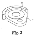
本発明に従って使用するのに適した形態を有する溶浸材は、多岐に亙る方法により作製することができる。1つの実施の形態において、合金の成分は組み合わされ、また、鋳造又は成形されたとき、ビレットを形成する均質な溶融塊を形成するのに十分な温度まで加熱される。形成されたビレットは、押出し成形し又は圧延して、ロッド、管、シート及び同様の物を含む鍛造形態物を提供することができる。押出成形した合金は、標準的な引き抜き法によってセグメントに分割し又は更に処理して可撓性のワイヤーを形成することもできる。新規な合金の鍛造形態は、均一な組成を有し、溶浸過程にて使用するため、有利な多岐に亙る形態及び(又は)形状となるように提供し又は順応させることができる。1つの実施の形態において、銅系溶浸材は、効率的な取り扱いのため、スプールに巻くことのできる引抜き成形したワイヤーの形態にて提供することができる。ワイヤーのセグメントは、適宜な量にて除去し且つ特定の溶浸過程にて使用するのに適した形状に順応させることができる。図1には、溶浸する前の粉体金属部品1の表面に順応し得るようにされたワイヤー20のセグメントが示されている。既知の寸法及び形状を有する極めて多数の部品を溶浸するステップを含む溶浸過程において、合金は、特定の用途に適した、ディスク、座金、ウェハ、シート、リング及びその他の形状を含む形態物にて提供することができる。図2、図3及び図4には、粉体金属部品2、3、4の表面にそれぞれ順応し得るようにされた、リング又は座金21、ディスク22及びウェハ23が示されている。図示したように、座金又はディスクのこれらの鍛造形態物の各々は、形成されたとき、溶浸すべき部品に対する寸法となるようにする必要がある一方、ワイヤー又はウェハ形態物の合金材料は、溶浸過程の前の任意の時点にて所望の形状となるような寸法とし且つその形状に順応させることができる。
An infiltrant having a form suitable for use in accordance with the present invention can be made by a variety of methods. In one embodiment, the alloy components are combined and, when cast or formed, heated to a temperature sufficient to form a homogeneous molten mass that forms a billet. The formed billet can be extruded or rolled to provide a forged form including rods, tubes, sheets and the like. The extruded alloy can be divided into segments or further processed by standard drawing methods to form flexible wires. The new alloy forging forms have a uniform composition and can be provided or adapted to be in a wide variety of advantageous forms and / or shapes for use in the infiltration process. In one embodiment, the copper-based infiltrant can be provided in the form of a pultruded wire that can be wound on a spool for efficient handling. The wire segments can be removed in an appropriate amount and adapted to a shape suitable for use in a particular infiltration process. FIG. 1 shows a segment of
溶浸に適した粉体金属部品は、多岐に亙る金属粉体から作製することができるが、鉄系金属部品がより一般に使用されている。素地部品と称されるかかる粉体金属部品は、典型的に既知の加圧又は成形技術により作製され、また、焼結し又は焼結しなくてもよい。次に、合金溶浸材は、典型的に、粉体金属部品と接触する位置に配置される。次に、組み合わせた構成要素に対し熱処理を加える。粉体金属部品との接触は、一般的に固体溶浸材によって行われるが、溶融溶浸材と接触させてもよい。例えば、加熱過程の間、溶浸材を粉体金属部品の上方に維持することにより、溶浸材の接触を遅らせ且つ加熱過程の間に形成された溶融溶浸溶材合金とのみの接触に制限することができる。溶浸材の寸法及び形状に依存して、粉体金属部品の上方に溶浸材合金を維持するため多岐に亙る手段が考えられる。熱処理は、選択随意的な冷却サイクルを含む1つ又はより多くの段階とすることができる。好ましくは、加熱過程は、還元雰囲気及び(又は)部分真空圧の下にて行われるものとする。 Powder metal parts suitable for infiltration can be made from a wide variety of metal powders, but ferrous metal parts are more commonly used. Such powder metal parts, referred to as green parts, are typically made by known pressing or molding techniques and may or may not be sintered. The alloy infiltrant is then typically placed in contact with the powder metal part. Next, heat treatment is applied to the combined components. The contact with the powder metal part is generally performed by a solid infiltrant, but may be brought into contact with the molten infiltrant. For example, by maintaining the infiltrant above the powder metal part during the heating process, the contact of the infiltrant is delayed and limited to contact only with the molten infiltrated alloy alloy formed during the heating process. can do. Depending on the size and shape of the infiltrant, various means are conceivable to maintain the infiltrant alloy above the powder metal part. The heat treatment can be in one or more stages, including an optional cooling cycle. Preferably, the heating process is performed under a reducing atmosphere and / or a partial vacuum pressure.
1つの形態において、過程は、粉体金属部品を合金溶浸材と接触させるステップを含む。次に、組み合わさった部品に対し、合金が溶融し又は液体となる迄、組み合わさった部品及び合金溶浸材を約950℃(1750F°)ないし約1150℃(2100F°)の範囲の温度にて還元雰囲気の下、加熱炉にて徐々に加熱するステップを含む、単一段階の熱処理を行う。組み合わさった部品に対し、溶融した合金が素地粉体金属部品の孔内に溶浸するのを許容するのに十分な時間、熱処理を行う。特定の実施の形態において、この時間は、約2分ないし約90分の範囲とすることができる。溶浸材の量、過程の温度及び(又は)時間は、粉体金属部品の全体を通じて均一な密度となるようある範囲の溶浸材の密度を有する部品を提供し得るよう所望に応じて調節することができる。 In one form, the process includes contacting the powder metal part with an alloy infiltrant. The combined part and alloy infiltrant are then brought to a temperature in the range of about 950 ° C. (1750 F °) to about 1150 ° C. (2100 F °) until the alloy is molten or liquid with respect to the combined part. A single-stage heat treatment including a step of gradually heating in a heating furnace under a reducing atmosphere is performed. The combined parts are heat treated for a time sufficient to allow the molten alloy to infiltrate into the pores of the base powder metal part. In certain embodiments, this time can range from about 2 minutes to about 90 minutes. The amount of infiltrant, the temperature of the process and / or the time is adjusted as desired to provide a part with a range of infiltrant density so that the density is uniform throughout the powder metal part. can do.
2段階熱処理の場合、粉体金属部品は、最初、高温度の焼結過程にて処理する。高温度の過程は、粉体金属部品に対し約5分ないし40分の範囲の時間期間、約950℃(1750F°)ないし約1150℃(2100F°)の範囲の温度を加える。その後、粉体金属部品及び溶浸材合金は、異なる状態下にて同一の加熱炉を通して再循環させるか又は第二の加熱炉に直接送ることができる。第二の熱処理は、組み合わさった部品を焼結するステップを含むことができる。この過程は、約5分ないし約90分の範囲の時間期間、約950℃(1750F°)ないし約1150℃(2100F°)の範囲の温度にて実行することができる。特定の実施の形態において、第一及び第二の段階の熱処理の双方は、還元雰囲気及び(又は)部分真空圧の下にて実行される。部品に対しこの溶浸処理を行った後、次に、溶浸した金属部品が冷却サイクルにて冷却するのを許容することができる。 In the case of a two-stage heat treatment, the powder metal part is first treated in a high temperature sintering process. The high temperature process applies a temperature in the range of about 950 ° C. (1750 F °) to about 1150 ° C. (2100 F °) for a time period in the range of about 5 to 40 minutes for the powder metal part. The powder metal part and the infiltrant alloy can then be recycled through the same furnace under different conditions or sent directly to the second furnace. The second heat treatment can include sintering the combined parts. This process can be carried out at a temperature in the range of about 950 ° C. (1750 F °) to about 1150 ° C. (2100 F °) for a time period in the range of about 5 minutes to about 90 minutes. In certain embodiments, both the first and second stage heat treatments are performed under a reducing atmosphere and / or partial vacuum pressure. After performing this infiltration treatment on the part, the infiltrated metal part can then be allowed to cool in the cooling cycle.
本発明に従った溶浸材及び溶浸過程は、格別に有利な効果を提供する。例えば、成分の混合体から成る銅系粉体溶浸材に対し、試料毎に相違する組成となるであろう粒子偏析を行う。更に、異なる粉体成分は、異なる率及び(又は)温度にて溶融させ且つ溶浸することができる。銅系粉体溶浸材と相違して、鍛造した溶浸材は、試料毎に一定のままである均一な組成を有する。更に、鍛造した合金は、均一に溶融し且つ溶浸する。更に、好ましい過程は、例えば、ステアリン酸金属塩又は合成ワックスのような溶浸材潤滑剤を必要とせず、しかも、所望であるとき、粉体金属部品の本質的に完全な溶浸材の稠密化、すなわち100%に近い溶浸密度を許容するよう実行することができる。過程は、例えば、85%ないし99%の範囲の密度のような所望の溶浸材の密度範囲を有する溶浸した粉体金属部品又は圧粉体を製造するため、変更することが可能であることは当該技術の当業者により理解されよう。 The infiltrant and the infiltration process according to the invention provide a particularly advantageous effect. For example, particle segregation that would have a different composition for each sample is performed on a copper-based powder infiltrant composed of a mixture of components. Furthermore, the different powder components can be melted and infiltrated at different rates and / or temperatures. Unlike a copper-based powder infiltrant, the forged infiltrant has a uniform composition that remains constant from sample to sample. Furthermore, the forged alloy is uniformly melted and infiltrated. Furthermore, the preferred process does not require an infiltrant lubricant such as, for example, a metal stearate salt or synthetic wax, and, if desired, the essentially complete infiltrant density of the powder metal part. Or infiltration density close to 100% can be performed. The process can be modified to produce infiltrated powder metal parts or green compacts having a desired infiltrant density range, for example, a density range of 85% to 99%. This will be understood by those skilled in the art.
この溶浸過程は、溶浸過程の結果として形状を殆ど変化させないが、本質的に100%溶浸された、すなわち溶浸密度の98%以上である溶浸された物品を提供することができる。これと代替的に、条件(例えば、熱処理の温度範囲、時間期間及び(又は)溶浸材中の銅の量)を変化させることにより、粉体金属部品に対し異なる程度の溶浸密度を付与することができる。このため、過程条件及び銅系合金溶浸材の量を慎重に選ぶことに基づいて、約85%ないし約98%+密度の溶浸密度を有する最終的な溶浸した金属部品を提供することができる。粉体金属部品の多孔度に依存して、本発明に従った銅系合金溶浸材を使用して、約8重量%ないし約20重量%の範囲の量だけ粉体金属製品の重量を増大させることができる。合金の鉛の成分はその他の成分よりも揮発性であるため、本発明に従って銅合金にて溶浸された溶浸した粉体金属部品は、溶浸条件に依存して、金属部品の性能に影響を与えることなく、減少したレベルの亜鉛を含むことができる。 This infiltration process may provide an infiltrated article that is substantially 100% infiltrated, ie, 98% or more of the infiltration density, with little change in shape as a result of the infiltration process. . Alternatively, varying degrees of infiltration density can be imparted to powder metal parts by changing conditions (eg, heat treatment temperature range, time period and / or amount of copper in the infiltrant). can do. Thus, providing a final infiltrated metal part having an infiltration density of about 85% to about 98% + density based on careful selection of process conditions and the amount of copper-based alloy infiltrant. Can do. Depending on the porosity of the powder metal part, the copper metal alloy infiltrant according to the present invention is used to increase the weight of the powder metal product by an amount in the range of about 8 wt% to about 20 wt%. Can be made. Because the lead component of the alloy is more volatile than the other components, infiltrated powder metal parts infiltrated with a copper alloy in accordance with the present invention depend on the infiltration conditions and can affect the performance of the metal part. It can contain reduced levels of zinc without affecting it.
本発明に従った過程は、溶浸材料に対し極めて高い溶浸効率及び生産性を提供し、一般に溶浸過程と関係した二次的工程を不要にすることができる。高い溶浸効率は、溶浸材の材料の損失量を減少させ、加圧コストを減少させ且つ清浄化コスト及びEPA/OSHAの問題を最小にする。更に、当該出願人の方法は、圧密化装置(compaction tooling)を必要とせず、取り扱いが容易な溶浸材を利用し、増大した密度を呈する溶浸した物品を製造し、また、全体として浸食及び溶浸材からの残留物が存在せず、典型的に、優れた性質を示す。こうした優れた性質は、全体として、例えば、1)全体として、均一な銅の分布状態、2)増大した横方向破断強度、3)増大した引張り強度、4)増大した降伏強度、5)増大した強度指数を含む。 The process according to the present invention provides very high infiltration efficiency and productivity for the infiltrated material, and can eliminate the secondary steps generally associated with the infiltration process. High infiltration efficiency reduces the amount of infiltrant material loss, reduces pressurization costs and minimizes cleaning costs and EPA / OSHA issues. Further, Applicants' method does not require compacting equipment, utilizes an infiltrant that is easy to handle, produces an infiltrated article that exhibits increased density, and is generally eroded. And no residue from the infiltrant typically presents excellent properties. These excellent properties as a whole, for example, 1) overall, uniform copper distribution, 2) increased transverse rupture strength, 3) increased tensile strength, 4) increased yield strength, 5) increased Includes strength index.
強度指数は、特定の強度を溶浸した物品の密度で割った比から得られる。例えば、横方向破断強度(TRS)指数の公式は次の通りである。
TRS指数=TRS(psi)/(密度(g/cm3)x104(倍率)) (等式1)
横方向破断強度に代えて、引張り強度及び降伏強度を代入することにより引張り強度(TS)指数及び降伏強度(YS)指数を、この公式から計算することができる。強度指数は、金属の単位質量にて実現される強度レベルに関する情報を提供し、また、標準的な物品から独立的である。その重量を増すことなく物品の強度を最大にすることは、低燃費の自動車の場合のように、軽量で且つ取り扱いが容易な装置を設計する際の重要な目標である。修正した強度指数(SI*)は、溶浸した物品の密度及び溶浸率の双方を更に反映することができる。修正した強度指数は、次の公式から計算することができる。
The strength index is obtained from the ratio of a specific strength divided by the density of the infiltrated article. For example, the formula for the transverse rupture strength (TRS) index is:
TRS index = TRS (psi) / (density (g / cm 3 ) × 10 4 (magnification)) (Equation 1)
Instead of the transverse breaking strength, the tensile strength (TS) index and the yield strength (YS) index can be calculated from this formula by substituting the tensile strength and the yield strength. The strength index provides information on the level of strength achieved in the unit mass of the metal and is independent of standard articles. Maximizing the strength of an article without increasing its weight is an important goal when designing a lightweight and easy to handle device, such as in a low fuel consumption automobile. The modified strength index (SI * ) can further reflect both the density and infiltration rate of the infiltrated article. The modified strength index can be calculated from the following formula:
修正したTRS指数(SI*)=TRS(psi)/(密度(g/cm3)x(溶浸率)4) (等式2)
横方向破断強度に代えて、引張り強度及び降伏強度を代入することにより、この公式から修正した引張り強度指数(TS SI*)及び降伏強度指数(YS SI*)を計算することができる。
Modified TRS index (SI * ) = TRS (psi) / (density (g / cm 3 ) × (infiltration rate) 4 ) (Equation 2)
The tensile strength index (TS SI * ) and the yield strength index (YS SI * ) modified from this formula can be calculated by substituting the tensile strength and the yield strength in place of the transverse breaking strength.
本発明は、当該技術の当業者に案出されるような改変例を考える。また、本発明にて具体化された過程における個別のステップは、本発明の精神から逸脱せずに当該技術の当業者に案出されるように変更し、削除し、反復し又はその他の過程に追加することが可能であるとも考えられる。更に、これらの過程における色々な段階、技術及び工程は、当該技術の当業者に案出されるように変更することができる。更に、本明細書に記載した任意の作動理論、証明又は知見は、本発明の理解を更に促進することを意味するが、本発明の範囲がかかる理論、証明又は知見に依存するものとすることを意図するものではない。 The present invention contemplates modifications as devised by those skilled in the art. Also, the individual steps in the process embodied in the present invention may be altered, deleted, repeated, or otherwise performed as devised by those skilled in the art without departing from the spirit of the present invention. It is also possible to add. Further, the various steps, techniques and processes in these processes can be modified as devised by those skilled in the art. Furthermore, any theory of operation, proof or knowledge described herein is meant to further facilitate understanding of the invention, but the scope of the invention shall depend on such theory, proof or knowledge. Is not intended.
以下の実施例には、本発明の特定の実施の形態に従って実現された改良された性質の幾つかが示されている。
実施例1−溶浸用の素地圧粉体の作製
試験片用の非焼結の圧粉体を、0.9重量%の黒鉛及び0.75重量%のアクラワックスC(Acrawax C)潤滑剤、アトメット28(Atomet 28)鉄粉体の混合体を圧密化することにより作製した。アトメット粉体は、カナダ、ケベック州J3R 4R4、マリー−ヴィクトリン トレイシー1655通りのケベックメタルパウダー(Quebec Metal Powder)Ltd.から入手可能であり、また、アクラワックスC潤滑剤は、ペンシルベニア州17701、ウイリアムスポート、3500トレントン街のロンザ インク(Lonza Inc.)から入手可能である。アクラワックスは、ニューヨーク州、ニューヨーク、4175番通りのチャス.L.ヒュースキング及びカンパニーインク(Chas.L.Huisking&Co.,Inc.)の登録商標名である。31.75mm(1.25インチ)の名目長さ、12.70mm(0.50インチ)の幅、6.35mm(0.25インチ)の厚さ、及び約6.7ないし7.0g/cm3の密度を有する矩形の形状の多孔性圧粉体6−1ないし6−5及び7−1ないし7−5を溶浸のため作製した。表Iに示したように、素地圧粉体は、溶浸前に測定した。
The following examples illustrate some of the improved properties realized in accordance with certain embodiments of the present invention.
Example 1-Fabrication of a green compact for infiltration A non-sintered green compact for a test piece was prepared by using 0.9% by weight of graphite and 0.75% by weight of Acrawax C lubricant. It was produced by compacting a mixture of Atomet 28 iron powder. Atmet powder is available from Quebec Metal Powder Ltd., Quebec, Canada, J3R 4R4, Marie-Victorin Tracy 1655 Street. Accra Wax C lubricant is available from Lonza Inc., 17701, Pennsylvania, Williamsport, 3500 Trenton Street. Accra Wax is a Chas. L. It is a registered trade name of Husking and Company Ink (Chas. L. Huisking & Co., Inc.). 31.75 mm (1.25 inch) nominal length, 12.70 mm (0.50 inch) width, 6.35 mm (0.25 inch) thickness, and about 6.7 to 7.0 g / cm Rectangular porous compacts 6-1 to 6-5 and 7-1 to 7-5 having a density of 3 were prepared for infiltration. As shown in Table I, the green compact was measured before infiltration.

実施例2−圧粉体の溶浸
約93%の銅、約3%のマンガン、約3%の亜鉛、約1%の鉄を含むワイヤー合金の個別の部分を選び且つ直ちに溶浸できるようにした。重量約2.4gのワイヤー合金の長さのもの試料6−1ないし6−5、試料7−1ないし7−5の各々の頂部に配置し、90/10 窒素/水素雰囲気下にて約30分間、1125℃にて試料を焼結し、次に、雰囲気温度まで冷却させた。形成される溶浸した圧粉体を、表IIに示したように再度測定した。約85%のように少ない銅を有するワイヤー合金のセグメントにて同様の結果を得ることができる。
Example 2-Infiltration of a green compact Individual parts of a wire alloy containing about 93% copper, about 3% manganese, about 3% zinc, about 1% iron can be selected and immediately infiltrated. did. A wire alloy length of about 2.4 g is placed on top of each of Samples 6-1 to 6-5 and Samples 7-1 to 7-5, and about 30 under a 90/10 nitrogen / hydrogen atmosphere. The sample was sintered for 1 minute at 1125 ° C. and then allowed to cool to ambient temperature. The infiltrated green compact formed was measured again as shown in Table II. Similar results can be obtained with segments of wire alloy having as little as about 85% copper.
実施例3−横方向破断強度及び硬度の決定
溶浸させた圧粉体の試料の特定のものにおける横方向破断強度及び硬度(HRB及びHRC)を次の方法によって決定した:MPIF標準的試験方法No.41、MPIF標準的試験方法No.43。得られた結果は、表IIIに掲げてある。
Example 3-Determination of transverse rupture strength and hardness The transverse rupture strength and hardness (HRB and HRC) in a particular infiltrated green compact sample were determined by the following method: MPIF standard test method No. 41, MPIF standard test method No. 43. The results obtained are listed in Table III.
実施例4−引張り強度、降伏強度及び延伸率の決定
試料6−6ないし6−10、7−6ないし7−10を、上述したように作製し且つ、ワイヤー溶浸材の12.1%及び11.4%にてそれぞれ焼結した。試料は平坦な引張り試験片の形状にて形成した。各試料の引張り強度、降伏強度及び延伸率は、MPIF標準的方法No.10により決定した。試料6−6ないし6−10、7−6ないし7−10の結果は、表IVに掲げてある。
Example 4 Determination of Tensile Strength, Yield Strength and Stretch Rate Samples 6-6 to 6-10, 7-6 to 7-10 were prepared as described above and 12.1% of the wire infiltrant and Sintered at 11.4%. The sample was formed in the shape of a flat tensile test piece. The tensile strength, yield strength and stretch ratio of each sample were determined by MPIF standard method No. 10. The results for Samples 6-6 through 6-10 and 7-6 through 7-10 are listed in Table IV.
実施例5−衝撃エネルギの決定
試料6−11ないし6−15及び7−11ないし7−15を上述したように作製し且つ、ワイヤー溶浸材の13.4%及び12.9%にてそれぞれ焼結した。試料は、アイゾット衝撃エネルギ試験片の形状にて形成した(すなわち、長さ75mm、幅及び厚さ10mm)。溶浸後試料の衝撃エネルギは、MPIF標準的試験方法No.40により決定した。試料6−11ないし6−15及び7−11ないし7−15の結果は、表Vに掲げてある。
Example 5-Determination of impact energy Samples 6-11 through 6-15 and 7-11 through 7-15 were prepared as described above and at 13.4% and 12.9% of the wire infiltrant, respectively. Sintered. The sample was formed in the form of an Izod impact energy specimen (ie, 75 mm long, 10 mm wide and 10 mm thick). The impact energy of the infiltrated sample is determined by MPIF standard test method no. 40. The results for Samples 6-11 through 6-15 and 7-11 through 7-15 are listed in Table V.
実施例6−異なる溶浸材を使用して溶浸した物品の性質の比較
以下の表VIには、本発明の合金(ワイヤー形態)及び粉体形態の銅合金にて溶浸した圧粉体の機械的強度の比較が要約されている。表VII及びVIIIには、上述した改良した溶浸過程により実現された横方向破断強度、引張り強度及び降伏強度の増大率を示す値が表形式にて要約されている。
Example 6-Comparison of properties of articles infiltrated using different infiltrants Table VI below lists green compacts infiltrated with alloys of the present invention (wire form) and copper alloys in powder form. A comparison of the mechanical strength of is summarized. Tables VII and VIII summarize in tabular values the rates of increase in transverse rupture strength, tensile strength and yield strength achieved by the improved infiltration process described above.
* MPIF FX−1008の性質は、ニュージャージー州08540−6692、プリンストン、105カレッジ道路東のメタルパウダーインダストリーズ連合(Metal Powder Industries Federation)が出版した「P/M構造用部品の材料標準(Materials Standards for P/M Structural Parts)」、23頁(2003年)から複製したものである。 * MPIF FX-1008 is characterized by "Materials Standards for P / M Material Parts for P" published by Metal Powder Industries Federation, Princeton, 105, College Road East, Princeton, New Jersey. / M Structural Parts), page 23 (2003).
** 単一の値は表III、IV及びVからの平均値である。
以下の表VIIには、本発明の合金(ワイヤー形態)及び既知の粉体金属溶浸したスチールMPIF FX−1008(粉体形態の溶浸材)にて溶浸した粉体金属圧粉体の横方向破断強度、引張り強度及び降伏強度の増加率及び試料の色々な強度指数(S.I.)の比較が要約されている。
** Single values are average values from Tables III, IV and V.
Table VII below shows the powder metal green compact infiltrated with the alloy of the present invention (wire form) and known powder metal infiltrated steel MPIF FX-1008 (powder form infiltrant). A summary of the transverse rupture strength, tensile strength and yield strength increases and comparison of the various strength indices (SI) of the samples is summarized.
実施例7−溶浸した金属部品内での銅の分布状態
上述の実施例2に記載したように、6−4、7−4として示した溶浸した試料について、上面及び底面から0.635mm(0.025インチ)の深さにて銅の含有率を分析した。試料6−4の上面及び底面の銅レベルは、それぞれ13.2重量%及び12.8重量%であった。試料7−4の上面及び底面の銅レベルは、それぞれ11.0重量%及び11.0重量%であった。このように、溶浸した粉体金属部品の全体に亙って全体として銅の均一な分布状態が実現された。
Example 7-Distribution of copper in infiltrated metal parts As described in Example 2 above, for the infiltrated samples shown as 6-4, 7-4, 0.635 mm from the top and bottom surfaces. The copper content was analyzed at a depth of (0.025 inch). The top and bottom copper levels of Sample 6-4 were 13.2 wt% and 12.8 wt%, respectively. The copper levels on the top and bottom surfaces of Sample 7-4 were 11.0 wt% and 11.0 wt%, respectively. Thus, a uniform distribution state of copper was realized as a whole over the entire infiltrated powder metal part.
実施例8−中間レベル及び最高レベルの溶浸
新規なワイヤー合金にて可能であるより高い溶浸レベルを決定するため、より多量の溶浸材を使用した点を除いて、91.6%の銅、1.9%の鉄、2.6%のマンガン、3.9%の亜鉛から成るワイヤー合金に対して実施例1ないし5の手順を反復した。合金の14.1%の溶浸は、通常通り実施される一方、14.3%という多量の合金にて溶浸した結果、試験片の一部の表面に少量の銅が溜まる結果となった。MPIF FX−1008で示した材料に相応する形成される溶浸した圧粉体の性質は、以下の表VIII、IX及びXに掲げられている。
Example 8-Intermediate level and highest level of infiltration 91.6%, except that a higher amount of infiltrant was used to determine the higher infiltration level possible with the novel wire alloy. The procedures of Examples 1-5 were repeated for a wire alloy consisting of copper, 1.9% iron, 2.6% manganese, 3.9% zinc. While 14.1% infiltration of the alloy was carried out as usual, as a result of infiltration with a large amount of 14.3% alloy, a small amount of copper was accumulated on the surface of a part of the test piece. . The properties of the infiltrated green compact formed corresponding to the material shown in MPIF FX-1008 are listed in Tables VIII, IX and X below.
実施例9−粉体合金圧粉体による溶浸
材料名MPIF FX−1008に相応する溶浸した圧粉体を形成するため、94.1%銅、1.7%鉄、2.8%マンガン及び1.4%亜鉛から成る粉体合金XF−5(ペンシルベニア州、ミードヴィル、18649ブレイキシュー通り)のU.S.ブロンズ(Bronze)から入手可能)に対し実施例8の手順を反復した。得られた結果は、以下の表XII、XIII、XIVに掲げられている。
Example 9-Infiltrate with powder alloy green compact To form an infiltrated green compact corresponding to MPIF FX-1008, 94.1% copper, 1.7% iron, 2.8% manganese And 1.4% zinc powder alloy XF-5 (Meadville, PA, 18649 Blakeshoe Avenue), U.S.A. S. The procedure of Example 8 was repeated (available from Bronze). The results obtained are listed in Tables XII, XIII, XIV below.
以下に掲げた表XVには、表IIIないしXIVのデータの平均値が要約されている。ワイヤー溶浸材の10ないし11%程度にて溶浸した物品は、多量の13.5%の粉体溶浸材にて溶浸した物品よりも横方向破断強度、引張り強度及び降伏強度が著しく大きかった。強度の測定値は完全又はほぼ完全な溶浸にて結合するものの、ワイヤー溶浸材は、典型的に、粉体溶浸材よりも大きい強度測定値を示す。 Table XV listed below summarizes the average values of the data in Tables III through XIV. Articles infiltrated with about 10 to 11% of the wire infiltrant have significantly higher transverse rupture strength, tensile strength and yield strength than articles infiltrated with a large amount of 13.5% powder infiltrant. It was big. While strength measurements bond with complete or near complete infiltration, wire infiltrates typically exhibit greater strength measurements than powder infiltrates.
* ワイヤー合金溶浸材ではなくて、粉体溶浸材を使用した。
以下に掲げた表XVIには、表VIIIないしXIVからの選んだデータが要約されている。この要約されたデータは、a)同等か又はより優れた機械的性質を提供し、b)より効率的に溶浸して、より高密度の溶浸した圧粉体を実現し、(c)必要とされる溶浸材の量を減少させることにより、溶浸した圧粉体のコストを減少させるという、少量のワイヤー合金溶浸材の能力を示す。少量の鍛造合金溶浸材(24ないし26%以下)にて高密度の素地圧粉体を溶浸することによって優れた機械的性質を実現する能力は、顕著なコスト削減効果を提供することができる。
* Powder infiltrant was used instead of wire alloy infiltrant.
Table XVI, listed below, summarizes selected data from Tables VIII through XIV. This summarized data includes: a) providing equivalent or better mechanical properties, b) infiltrating more efficiently to achieve a denser infiltrated green compact, and (c) required It shows the ability of a small amount of wire alloy infiltrant to reduce the cost of the infiltrated green compact by reducing the amount of infiltrant taken. The ability to achieve superior mechanical properties by infiltrating a dense green compact with a small amount of forged alloy infiltrant (24-26% or less) can provide significant cost savings. it can.
* 6.65g/cm3の素地密度のデータ
** 6.75g/cm3の素地密度のデータ
実施例10−新規な銅溶浸合金の作製
重量比にて92部分の銅と、重量比にて3部分のマンガンと、重量比にて3部分の亜鉛と、重量比にて2部分の鉄とを含む混合体を約2100℃に加熱して均質な溶融体を形成した。溶融塊は、鋳型に搬送し、熱を除去し、鋳型から形成されたビレットを除去した。ビレットは、過熱し且つ押出し成形して約6.35mm(4分の1インチ)の断面直径を有するロッドを形成した。同様の態様にて、ビレットを押出し成形し、管を形成し又は圧延してシートを形成することができる。形成されたロッドは、引抜いて直径約2.36mm(0.093インチ)のワイヤーになるようにした。同様に、形成されたロッドは、圧延して合金シートを形成することができる。ロッド及び管をその長手方向軸線に沿って切断することにより、広範囲な直径を有するロッド及び管からディスク及び座金の形状を有する溶浸材を形成することができる。ウェハの形状を有する溶浸材は、シートの形態にて合金から形成し、又は四角形、矩形又はその他の断面形状を有するロッドの断面を切断することにより形成することができる。合金のワイヤー形態物からリング又は円環形状を有する溶浸材を、形成することができる。合金のワイヤー形態は、スプール及び同様の物に巻いて輸送、格納及び取り扱いを簡略化することができる。ワイヤーは、全体として均一な密度を有するため、溶浸材の重量をワイヤー又はリボンの断面長さに便宜に関係付けることができる。
* 6.65 g / cm 3 density data
** Data on substrate density of 6.75 g / cm 3
Example 10-Preparation of a novel copper infiltrated alloy 92 parts copper by weight, 3 parts manganese by weight, 3 parts zinc by weight, and 2 parts iron by weight Was heated to about 2100 ° C. to form a homogeneous melt. The molten mass was conveyed to a mold, heat was removed, and billets formed from the mold were removed. The billet was superheated and extruded to form a rod having a cross-sectional diameter of about 6.35 mm (1/4 inch). In a similar manner, billets can be extruded and formed into tubes or rolled to form sheets. The formed rod was drawn out into a wire with a diameter of about 2.36 mm (0.093 inch). Similarly, the formed rod can be rolled to form an alloy sheet. By cutting the rod and tube along their longitudinal axis, an infiltrant with a disk and washer shape can be formed from rods and tubes having a wide range of diameters. The infiltrant having the shape of a wafer can be formed from an alloy in the form of a sheet, or by cutting a cross section of a rod having a square, rectangular or other cross-sectional shape. An infiltrant with a ring or ring shape can be formed from the wire form of the alloy. The alloy wire form can be wound on spools and the like to simplify transport, storage and handling. Since the wire has a uniform density as a whole, the weight of the infiltrant can be conveniently related to the cross-sectional length of the wire or ribbon.
重量比にて約85%の銅と、重量比にて約0.5%ないし約5.5%のマンガンと、重量比にて約0.5%ないし約5.5%の亜鉛と、重量比にて約0.5%ないし約3.5%の鉄とを有する銅合金を、本発明に従って作製し且つ上述した色々な形態の鍛造溶浸材物品に形成することができる。かかる物品は、特に、優れた物理的性質を有する溶浸した粉体金属部品を提供するのに適している。 About 85% copper by weight, about 0.5% to about 5.5% manganese by weight, about 0.5% to about 5.5% zinc by weight, and weight Copper alloys having a ratio of about 0.5% to about 3.5% iron can be made according to the present invention and formed into the various forms of forged infiltrant articles described above. Such articles are particularly suitable for providing infiltrated powder metal parts having excellent physical properties.
実施例11−XF−5粉体溶浸材及びワイヤー合金溶浸材の化学的分析
U.S.ブロンズ(Bronze)から入手可能なXF−5粉体溶浸材及び本発明のワイヤー合金溶浸材(実施例8にて説明)の試料をバルク分析した。微量な元素及び僅かな不純物は測定されなかった。その結果は、表XVIIに掲げられている。
Example 11-Chemical analysis of XF-5 powder infiltrant and wire alloy infiltrant S. Samples of the XF-5 powder infiltrant available from Bronze and the wire alloy infiltrant of the present invention (described in Example 8) were bulk analyzed. Trace elements and slight impurities were not measured. The results are listed in Table XVII.
実施例12−XF−5粉体及びワイヤー合金中の金属の分布
XF−5粉体の一部分をエポキシ樹脂内に分散させ且つ、試料鋳型内に鋳込んで複合的試料を形成した。複合体の断面を研磨して個々の粉体物品の断面を露出させた。ワイヤー合金は断面化し且つ取り付けて、その長手方向(ワイヤーの引抜き方向)を測定した。粉体複合材及びワイヤーの断面は、SEM−EDS分析法により測定した。
Example 12-Distribution of XF-5 powder and metal in wire alloy A portion of XF-5 powder was dispersed in an epoxy resin and cast into a sample mold to form a composite sample. The cross section of the composite was polished to expose the cross sections of the individual powder articles. The wire alloy was sectioned and attached, and its longitudinal direction (wire drawing direction) was measured. The cross sections of the powder composite material and the wire were measured by SEM-EDS analysis.
図5には、粉体粒子複合材の断面図及び元素Mn、Fe、Znのドットマップが示されている。ドットの数及び分布状態は、存在する金属元素の量及び粒子を亙るその分布状態を表わす。図6には、ワイヤー合金の断面図及びドットマップが示されている。極めて多数のドットであることは、金属含有率が高いことを表わし、また、ドットの分布が均一であることは、金属要素がワイヤー合金の全体に亙って均一に分布していることを表わす。図5及び図6には、粉体は粉体の全体を亙って均一に分布した金属量が少ないことを表わす一方、ワイヤーは、ワイヤー断面の全体に亙って均一に分布した多量の金属含有分を含むことを示す。 FIG. 5 shows a cross-sectional view of the powder particle composite material and a dot map of the elements Mn, Fe, and Zn. The number and distribution of dots represent the amount of metal element present and its distribution over the particles. FIG. 6 shows a cross-sectional view and a dot map of the wire alloy. A very large number of dots indicates a high metal content, and a uniform distribution of dots indicates that the metal elements are uniformly distributed throughout the wire alloy. . 5 and 6 show that the powder has a small amount of metal uniformly distributed over the entire powder, while the wire has a large amount of metal uniformly distributed over the entire wire cross section. Indicates that the content is included.
実施例13−非均質なXF−5粉体中の非合金化Feの証明
小型の磁石をXF−5粉体溶浸材の試料中に配置した。磁石を除去したとき、先端は、磁石の先端の磁界と整合させた微細な灰色粒子にて被覆され、XF−5粉体中に非合金の鉄粒子が存在することを示すことが分かった。
Example 13-Demonstration of non-alloyed Fe in non-homogeneous XF-5 powder A small magnet was placed in a sample of XF-5 powder infiltrant. It was found that when the magnet was removed, the tip was covered with fine gray particles aligned with the magnetic field at the tip of the magnet, indicating the presence of non-alloyed iron particles in the XF-5 powder.
実施例14−XF−5粉体及びワイヤー合金の元素分析スペクトル
バルクXF−5粉体の試料の元素分析スペクトルを測定し、その結果は、図7に掲げてある。微量のアルミニウム及びチタンが存在することが分かった。予想されたように、銅は、主要な成分であることが示されている。しかし、鉄のレベルは、マンガンのレベルよりも僅かに多いように思われ、このことは、実施例11にて掲げたバルク分析と一致しない。バルク分析と一致しないが、結果は、粉体溶浸材が析出可能である個別の粉体粒子の混合体である場合と一致し、また、試料採取及び粒子の分布状態に依存して、試料毎に可変の組成であることを実証する。
Example 14 Elemental Analysis Spectra of XF-5 Powder and Wire Alloy Elemental analysis spectra of bulk XF-5 powder samples were measured and the results are listed in FIG. Traces of aluminum and titanium were found to be present. As expected, copper has been shown to be a major component. However, the iron level appears to be slightly higher than the manganese level, which is inconsistent with the bulk analysis listed in Example 11. Although not consistent with bulk analysis, the results are consistent with the case where the powder infiltrant is a mixture of individual powder particles that can be deposited, and depending on the sampling and particle distribution, the sample Demonstrate variable composition every time.
ワイヤー合金の元素分析スペクトルを同様に測定し、その結果は、図8に掲げられている。図8の左側の標識しない大きいピーク値は、ワイヤー合金試料にスパッタ被覆され、十分な導電率を保証する金である。粉体と同様に、銅のピークは最大であり、銅は合金の90%以上を占める。粉体と相違して、マンガンのピークは、鉄のピークよりも高く、このことはバルク分析と一致する。ワイヤー合金の元素分析は、全体として均一な組成を有するワイヤー合金の場合と一致する。 The elemental analysis spectrum of the wire alloy was measured in the same manner, and the result is shown in FIG. The large unlabeled peak value on the left side of FIG. 8 is gold that is sputter coated onto the wire alloy sample to ensure sufficient conductivity. Like the powder, the copper peak is the largest, with copper accounting for over 90% of the alloy. Unlike the powder, the manganese peak is higher than the iron peak, which is consistent with the bulk analysis. The elemental analysis of the wire alloy is consistent with the case of the wire alloy having a uniform composition as a whole.
実施例15−個別のXF−5粉体粒子の元素分析
図9には、XF−5粉体粒子の分布状態が250xの倍率にて示されている。個別に選んだ粒子が参照番号1、2、3で示されている。粒子1、2、3に対する個別の元素スペクトルを測定し、これらは、図10、図11、図12にそれぞれ示されている。図10から明らかであるように、粒子1は、実質的に純粋なマンガン粒子である。小さい銅のピーク値は、より大きい近傍の銅粒子からの背景的(background)測定値である。図11から理解し得るように、粒子2は、約10%の含有率の亜鉛と、少量のチタン及び鉄不純物とを含む黄銅粒子であるものと思われる。図12に示した粒子3のスペクトルは、粒子3がほぼ純粋な銅粒子であることを示す。磁気的研究(実施例13)、元素分析(実施例14)及び個別のXF−5粒子の分析(この実施例)に基づき、XF−5の粉体は、銅、銅/亜鉛黄銅合金、鉄及びマンガンの不均質な混合体である。これに反して、提供されたスペクトルの証拠の全ては、ワイヤー合金は銅、鉄、亜鉛及びマンガンから成る実質的な均質な合金であることを示す。
Example 15 Elemental Analysis of Individual XF-5 Powder Particles FIG. 9 shows the distribution of XF-5 powder particles at a magnification of 250 ×. Individually selected particles are indicated by
本発明は、上記の説明及び実施例にて示し且つ詳細に説明したが、これは特徴の一例であり、制限的なものではなく、好ましい実施の形態のみを示し且つ記載したものであり、本発明の精神に属する全ての変更例及び改変例が包含されることを望むものであることを理解すべきである。 While the invention has been shown and described in detail in the foregoing description and examples, it is by way of example only and not restrictive, and only shows and describes preferred embodiments. It should be understood that all changes and modifications that come within the spirit of the invention are desired to be included.
Claims (34)
a)粉体金属部品を選ぶステップと、
b)粉体金属部品の表面と接触し得るようにされた鍛造形態物(wrought form)を有する銅合金であって、(i)少なくとも約85重量%の銅と、ii)約0.5ないし約3.5重量%の鉄と、iii)約0.5ないし約5.5重量%のマンガンと、iv)約0.5ないし約5.5重量%の亜鉛とから成る前記銅合金を選ぶステップと、
c)合金を粉体金属部品の表面と接触させるステップと、
d)合金及び粉体金属材料を合金が溶融し且つ粉体金属部品を溶浸させるのに十分な温度まで加熱するステップとを備える、粉体金属部品を溶浸する方法。 In the method of infiltrating powder metal parts,
a) selecting powder metal parts;
b) a copper alloy having a wrought form adapted to contact the surface of the powder metal part, wherein (i) at least about 85% by weight of copper, and ii) about 0.5 to about Selecting the copper alloy comprising about 3.5% iron, iii) about 0.5 to about 5.5% manganese, and iv) about 0.5 to about 5.5% zinc. Steps,
c) contacting the alloy with the surface of the powder metal part;
d) heating the alloy and the powder metal material to a temperature sufficient to melt the alloy and infiltrate the powder metal part.
合金は少なくとも約90重量%の銅を含む、方法。 The method of claim 1, wherein
The method wherein the alloy comprises at least about 90 wt% copper.
粉体金属部品は鉄系粉体合金部品である、方法。 The method of claim 1, wherein
The method, wherein the powder metal part is an iron-based powder alloy part.
粉体金属部品は焼結した金属部品である、方法。 The method of claim 3, wherein
The method, wherein the powder metal part is a sintered metal part.
粉体金属部品の表面は上面である、方法。 The method of claim 1, wherein
The method, wherein the surface of the powder metal part is the top surface.
温度は少なくとも約800℃である、方法。 The method of claim 1, wherein
The method, wherein the temperature is at least about 800 ° C.
鍛造形態物はワイヤーセグメントである、方法。 The method of claim 1, wherein
The method, wherein the forging feature is a wire segment.
鍛造形態物はウェハである、方法。 The method of claim 1, wherein
The method, wherein the forging feature is a wafer.
鍛造形態物はディスクである、方法。 The method of claim 1, wherein
The method, wherein the forging feature is a disk.
鍛造形態物は座金である、方法。 The method of claim 1, wherein
The method, wherein the forged form is a washer.
加熱は雰囲気圧力以下にて実行される、方法。 The method of claim 1, wherein
A method wherein heating is performed at or below atmospheric pressure.
加熱は高還元雰囲気にて実行される、方法。 The method of claim 1, wherein
Heating is performed in a highly reducing atmosphere.
ワイヤーセグメントは全体として円環状の形態を有する、方法。 The method of claim 7, wherein
The method wherein the wire segment has a generally annular shape.
d)約0.5ないし約5.5重量%の亜鉛とを含む前記銅合金から成る粉体金属部品を溶浸する材料。 2. A copper alloy having a homogeneous forged form that can be adapted to conform to the surface of a powder metal part, comprising a) at least about 85% by weight copper, and b) from about 0.5 to about 3. 5% iron, c) about 0.5 to about 5.5% manganese,
d) A material for infiltrating powder metal parts made of said copper alloy containing about 0.5 to about 5.5 wt.% zinc.
銅合金は少なくとも約90重量%の銅を含む、材料。 The material according to claim 14, wherein
The material, wherein the copper alloy comprises at least about 90 weight percent copper.
鍛造形態は、ディスク、リング、シート、ウェハ、ワイヤーセグメント及び座金から成る群から選ばれる、材料。 The material according to claim 14, wherein
The forging form is a material selected from the group consisting of discs, rings, sheets, wafers, wire segments and washers.
形態物はワイヤーセグメントである、材料。 The material according to claim 16, wherein
The material is a wire segment.
粉体金属部品は鉄系合金であり、溶浸した部品は全体として均一な銅の分布状態を有する、溶浸した粉体金属部品。 An infiltrated powder metal part made according to the method of claim 1,
The powder metal part is an iron alloy, and the infiltrated part has a uniform copper distribution as a whole.
少なくとも約0.8の修正した横方向破断強度指数(modified transverse rupture strength index)を有する、溶浸した粉体金属部品。 The infiltrated powder metal part according to claim 18,
An infiltrated powder metal part having a modified transversal strength strength index of at least about 0.8.
少なくとも約0.7の修正した引張り強度指数を有する、溶浸した粉体金属部品。 The infiltrated powder metal part according to claim 18,
Infiltrated powder metal parts having a modified tensile strength index of at least about 0.7.
少なくとも約0.5の修正した降伏強度指数を有する、溶浸した粉体金属部品。 The infiltrated powder metal part according to claim 18,
Infiltrated powder metal parts having a modified yield strength index of at least about 0.5.
a)少なくとも約85重量%の銅と、約0.5ないし約3.5重量%の鉄と、約0.5ないし約5.5重量%のマンガンと、約0.5ないし約5.5重量%の亜鉛とを含む混合体を形成するステップと、
b)該混合体を均質な溶融塊を形成するのに十分な温度まで加熱するステップと、
c)金属部品を溶浸する目的のため、溶融塊を、粉体金属部品の表面と接触し得るようにすることのできる均質な鍛造形態物に転換するステップとを備える、溶浸合金を作製する方法。 In the method of making the infiltrated alloy,
a) at least about 85 weight percent copper, about 0.5 to about 3.5 weight percent iron, about 0.5 to about 5.5 weight percent manganese, and about 0.5 to about 5.5; Forming a mixture comprising weight percent zinc;
b) heating the mixture to a temperature sufficient to form a homogeneous molten mass;
c) producing an infiltrated alloy for the purpose of infiltrating the metal part comprising converting the molten mass into a homogeneous forged form capable of being brought into contact with the surface of the powder metal part how to.
a)溶融塊を鋳型内に移送するステップと、
b)溶融塊を凝固させてビレットを形成するステップと、
c)ビレットを押出し成形して実質的に均質な鍛造形態の合金を提供するステップとを備える、方法。 23. The method of claim 22, wherein melting the molten mass comprises
a) transferring the molten mass into a mold;
b) solidifying the molten mass to form a billet;
c) extruding the billet to provide a substantially homogeneous forged form of the alloy.
ビレットは、押出し成形する前にその融点以下の高温度まで加熱される、方法。 24. The method of claim 23, wherein
The billet is heated to a high temperature below its melting point before extrusion.
混合体は、少なくとも約1150℃の温度まで加熱される、方法。 25. The method of claim 24, wherein
The method wherein the mixture is heated to a temperature of at least about 1150 ° C.
鍛造形態物はロッドである、方法。 25. The method of claim 24, wherein
The method, wherein the forging feature is a rod.
鍛造形態物は管である、方法。 25. The method of claim 24, wherein
The method, wherein the forged form is a tube.
鍛造形態物はシートである、方法。 25. The method of claim 24, wherein
The method, wherein the forged form is a sheet.
ロッドは、粉体金属部品の表面と接触し得るようにされたディスクを形成すべくその長手方向軸線を渡って切断される、方法。 27. The method of claim 26.
A method wherein the rod is cut across its longitudinal axis to form a disk adapted to contact the surface of the powder metal part.
管は、粉体金属部品の表面と接触し得るようにされた座金を形成すべくその長手方向軸線を渡って切断される、方法。 28. The method of claim 27, wherein
The method wherein the tube is cut across its longitudinal axis to form a washer adapted to contact the surface of the powder metal part.
シートは、粉体金属部品の表面と接触し得るようにされた形態を有するウェハに転換される、方法。 The method of claim 28, wherein
The method wherein the sheet is converted into a wafer having a form adapted to be in contact with the surface of the powder metal part.
ロッドはワイヤーを形成するよう引き抜かれる、方法。 27. The method of claim 26.
A method in which the rod is withdrawn to form a wire.
ワイヤーはセグメントに切断され、セグメントは粉体金属部品の表面に順応する形状とされる、方法。 The method of claim 32, wherein
A method in which the wire is cut into segments and the segments are shaped to conform to the surface of the powder metal part.
セグメントは円環状の形状に適合するようにされる、方法。 34. The method of claim 33, wherein
A method wherein the segments are adapted to conform to an annular shape.
Applications Claiming Priority (3)
| Application Number | Priority Date | Filing Date | Title |
|---|---|---|---|
| US65233305P | 2005-02-11 | 2005-02-11 | |
| US11/348,975 US7341093B2 (en) | 2005-02-11 | 2006-02-07 | Copper-based alloys and their use for infiltration of powder metal parts |
| PCT/US2006/004301 WO2006086393A2 (en) | 2005-02-11 | 2006-02-08 | Copper-based alloys and their use for infiltration of powder metal parts |
Publications (1)
| Publication Number | Publication Date |
|---|---|
| JP2008533295A true JP2008533295A (en) | 2008-08-21 |
Family
ID=36793646
Family Applications (1)
| Application Number | Title | Priority Date | Filing Date |
|---|---|---|---|
| JP2007555176A Pending JP2008533295A (en) | 2005-02-11 | 2006-02-08 | Use to infiltrate copper alloys and their powder metal parts |
Country Status (11)
| Country | Link |
|---|---|
| US (4) | US7341093B2 (en) |
| EP (1) | EP1850990B1 (en) |
| JP (1) | JP2008533295A (en) |
| KR (1) | KR20070108542A (en) |
| CN (1) | CN1942601B (en) |
| AU (1) | AU2006212804A1 (en) |
| BR (1) | BRPI0606966B1 (en) |
| CA (1) | CA2597064A1 (en) |
| MX (1) | MX2007009452A (en) |
| TW (1) | TWI394851B (en) |
| WO (1) | WO2006086393A2 (en) |
Families Citing this family (8)
| Publication number | Priority date | Publication date | Assignee | Title |
|---|---|---|---|---|
| WO2008086088A2 (en) * | 2007-01-03 | 2008-07-17 | United States Bronze Powders, Incorporated | Enhancement of material properties by infiltration of powder metal part: formulation and method of application thereof |
| CN103014610A (en) * | 2012-11-22 | 2013-04-03 | 宁波市群星粉末冶金有限公司 | Copper infiltration agent for powder metallurgy |
| CN104439251B (en) * | 2014-10-24 | 2016-09-28 | 青岛金智高新技术有限公司 | A kind of Copper infiltration agent for powder metallurgy |
| RU2629402C1 (en) * | 2016-12-06 | 2017-08-29 | Юлия Алексеевна Щепочкина | Sintered copper based alloy |
| RU2629403C1 (en) * | 2016-12-06 | 2017-08-29 | Юлия Алексеевна Щепочкина | Sintered copper based alloy |
| US11014032B2 (en) * | 2017-01-19 | 2021-05-25 | Scavenger Manufacturing LLC | Anti-corrosion fluid filter system |
| WO2019108430A1 (en) | 2017-11-30 | 2019-06-06 | Gkn Sinter Metals, Llc | Powder metal alloy composition for sintered powder metal insert for aluminum casting |
| JP6467535B1 (en) * | 2018-02-13 | 2019-02-13 | 福田金属箔粉工業株式会社 | Cu-based powder for infiltration |
Citations (6)
| Publication number | Priority date | Publication date | Assignee | Title |
|---|---|---|---|---|
| JPS63183105A (en) * | 1987-01-26 | 1988-07-28 | Meidensha Electric Mfg Co Ltd | Production of electrode material |
| JPS63313442A (en) * | 1987-06-16 | 1988-12-21 | Meidensha Electric Mfg Co Ltd | Manufacture of electrode material |
| JPH04198407A (en) * | 1990-11-29 | 1992-07-17 | Kawasaki Steel Corp | Sintered metal mold and production thereof |
| JPH08291035A (en) * | 1995-04-24 | 1996-11-05 | Kao Corp | Hair-dressing agent composition |
| JPH09235646A (en) * | 1996-02-29 | 1997-09-09 | Daido Metal Co Ltd | Sintered sliding member and its production |
| WO2005077571A1 (en) * | 2004-02-04 | 2005-08-25 | Gkn Sinter Metals, Inc. | Sheet material infiltration of powder metal parts |
Family Cites Families (32)
| Publication number | Priority date | Publication date | Assignee | Title |
|---|---|---|---|---|
| US2817601A (en) * | 1953-05-25 | 1957-12-24 | Gen Motors Corp | Method of impregnating a porous metal article |
| US3429696A (en) * | 1966-08-05 | 1969-02-25 | New Jersey Zinc Co | Iron powder infiltrant |
| US3619170A (en) * | 1969-07-24 | 1971-11-09 | Scm Corp | Copper infiltrating composition for porous ferruginous parts |
| GB1399812A (en) | 1971-10-23 | 1975-07-02 | Brico Eng | Sintered metal articles |
| US4003715A (en) * | 1973-12-21 | 1977-01-18 | A. Johnson & Co. Inc. | Copper-manganese-zinc brazing alloy |
| US3960554A (en) * | 1974-06-03 | 1976-06-01 | Westinghouse Electric Corporation | Powdered metallurgical process for forming vacuum interrupter contacts |
| GB1519589A (en) | 1974-09-11 | 1978-08-02 | Brico Eng | Metal articles of aluminium having load-bearing inserts |
| US3956027A (en) * | 1975-04-09 | 1976-05-11 | Olin Corporation | Processing copper base alloys |
| US4168162A (en) | 1978-09-22 | 1979-09-18 | Scm Corporation | Infiltrating powder composition |
| GB2087929B (en) | 1980-11-19 | 1985-01-09 | Brico Eng | Sintered metal articles and their manufacture |
| JPS58152982A (en) | 1982-03-09 | 1983-09-10 | Honda Motor Co Ltd | High rigidity valve sheet ring made of sintered alloy in double layer |
| KR890004522B1 (en) | 1982-09-06 | 1989-11-10 | 미쯔비시긴조구 가부시기가이샤 | Manufacture of copper infilterated sintered iron alloy member and double layer valve made of fe group sintered material |
| US4671491A (en) | 1984-06-12 | 1987-06-09 | Sumitomo Electric Industries, Ltd. | Valve-seat insert for internal combustion engines and its production |
| US4731118A (en) | 1986-06-25 | 1988-03-15 | Scm Metal Products, Inc. | High impact strength power metal part and method for making same |
| US4606768A (en) | 1985-07-15 | 1986-08-19 | Scm Corporation | High impact strength powder metal part and method for making same |
| US4861373A (en) | 1985-07-15 | 1989-08-29 | Scm Metal Products, Inc. | Infiltrated powder metal part having improved impact strength tensile strength and dimensional control and method for making same |
| US4822560A (en) | 1985-10-10 | 1989-04-18 | The Furukawa Electric Co., Ltd. | Copper alloy and method of manufacturing the same |
| US4769071A (en) | 1987-08-21 | 1988-09-06 | Scm Metal Products, Inc | Two-step infiltration in a single furnace run |
| US4976778A (en) | 1988-03-08 | 1990-12-11 | Scm Metal Products, Inc. | Infiltrated powder metal part and method for making same |
| GB8921826D0 (en) | 1989-09-27 | 1989-11-08 | Brico Eng | Valve guide |
| JPH03158445A (en) | 1989-11-16 | 1991-07-08 | Mitsubishi Materials Corp | Valve seat made of fe-base sintered alloy excellent in wear resistance |
| US5370840A (en) * | 1992-11-04 | 1994-12-06 | Olin Corporation | Copper alloy having high strength and high electrical conductivity |
| DE69432546T2 (en) | 1993-09-16 | 2003-11-20 | Sumitomo Electric Industries | Metal housing for semiconductor device and method for its production |
| US5672435A (en) * | 1994-12-12 | 1997-09-30 | The Dow Chemical Company | Hard disk drive components and methods of making same |
| DE19507179C1 (en) * | 1995-03-02 | 1996-03-28 | Krupp Vdm Gmbh | Catalyst for oxidn. of gaseous sulphur cpds. esp. hydrogen sulphide |
| US6254701B1 (en) * | 1996-03-14 | 2001-07-03 | Taiho Kogyo Co., Ltd. | Copper alloy and sliding bearing having improved seizure resistance |
| US5925836A (en) | 1997-11-04 | 1999-07-20 | Magnetics International Inc. | Soft magnetic metal components manufactured by powder metallurgy and infiltration |
| JP3312585B2 (en) * | 1997-11-14 | 2002-08-12 | 三菱マテリアル株式会社 | Valve seat made of Fe-based sintered alloy with excellent wear resistance |
| DE19900388A1 (en) | 1999-01-08 | 2000-07-13 | Gkn Sinter Metals Holding Gmbh | Method for connecting a sintered body to a metallic carrier element |
| US6551373B2 (en) | 2000-05-11 | 2003-04-22 | Ntn Corporation | Copper infiltrated ferro-phosphorous powder metal |
| US20030131476A1 (en) * | 2001-09-28 | 2003-07-17 | Vlad Ocher | Heat conduits and terminal radiator for microcircuit packaging and manufacturing process |
| US6676894B2 (en) | 2002-05-29 | 2004-01-13 | Ntn Corporation | Copper-infiltrated iron powder article and method of forming same |
-
2006
- 2006-02-07 US US11/348,975 patent/US7341093B2/en active Active
- 2006-02-08 AU AU2006212804A patent/AU2006212804A1/en not_active Abandoned
- 2006-02-08 JP JP2007555176A patent/JP2008533295A/en active Pending
- 2006-02-08 EP EP06734507.4A patent/EP1850990B1/en active Active
- 2006-02-08 CN CN2006800000221A patent/CN1942601B/en not_active Expired - Fee Related
- 2006-02-08 WO PCT/US2006/004301 patent/WO2006086393A2/en active Application Filing
- 2006-02-08 KR KR1020077020762A patent/KR20070108542A/en not_active Application Discontinuation
- 2006-02-08 CA CA002597064A patent/CA2597064A1/en not_active Abandoned
- 2006-02-08 BR BRPI0606966A patent/BRPI0606966B1/en not_active IP Right Cessation
- 2006-02-08 MX MX2007009452A patent/MX2007009452A/en active IP Right Grant
- 2006-02-09 TW TW095104320A patent/TWI394851B/en not_active IP Right Cessation
-
2008
- 2008-01-07 US US11/970,200 patent/US20080138237A1/en not_active Abandoned
-
2009
- 2009-07-31 US US12/533,624 patent/US20100206509A1/en not_active Abandoned
-
2016
- 2016-03-24 US US15/079,099 patent/US20170021421A1/en not_active Abandoned
Patent Citations (7)
| Publication number | Priority date | Publication date | Assignee | Title |
|---|---|---|---|---|
| JPS63183105A (en) * | 1987-01-26 | 1988-07-28 | Meidensha Electric Mfg Co Ltd | Production of electrode material |
| JPS63313442A (en) * | 1987-06-16 | 1988-12-21 | Meidensha Electric Mfg Co Ltd | Manufacture of electrode material |
| JPH04198407A (en) * | 1990-11-29 | 1992-07-17 | Kawasaki Steel Corp | Sintered metal mold and production thereof |
| JPH08291035A (en) * | 1995-04-24 | 1996-11-05 | Kao Corp | Hair-dressing agent composition |
| JPH09235646A (en) * | 1996-02-29 | 1997-09-09 | Daido Metal Co Ltd | Sintered sliding member and its production |
| WO2005077571A1 (en) * | 2004-02-04 | 2005-08-25 | Gkn Sinter Metals, Inc. | Sheet material infiltration of powder metal parts |
| JP2007520635A (en) * | 2004-02-04 | 2007-07-26 | ジーケーエヌ シンター メタルズ, インコーポレーテッド | Sheet material infiltration of powder metal parts |
Also Published As
| Publication number | Publication date |
|---|---|
| US20080138237A1 (en) | 2008-06-12 |
| EP1850990A2 (en) | 2007-11-07 |
| CN1942601B (en) | 2010-05-26 |
| US20060180251A1 (en) | 2006-08-17 |
| CN1942601A (en) | 2007-04-04 |
| WO2006086393A3 (en) | 2007-02-01 |
| BRPI0606966B1 (en) | 2015-09-29 |
| WO2006086393A8 (en) | 2006-10-26 |
| TW200700568A (en) | 2007-01-01 |
| EP1850990B1 (en) | 2013-06-19 |
| CA2597064A1 (en) | 2006-08-17 |
| US20170021421A1 (en) | 2017-01-26 |
| TWI394851B (en) | 2013-05-01 |
| MX2007009452A (en) | 2008-03-06 |
| KR20070108542A (en) | 2007-11-12 |
| US7341093B2 (en) | 2008-03-11 |
| AU2006212804A1 (en) | 2006-08-17 |
| WO2006086393A2 (en) | 2006-08-17 |
| BRPI0606966A2 (en) | 2009-07-28 |
| EP1850990A4 (en) | 2011-05-25 |
| US20100206509A1 (en) | 2010-08-19 |
Similar Documents
| Publication | Publication Date | Title |
|---|---|---|
| US10294552B2 (en) | Rapidly solidified high-temperature aluminum iron silicon alloys | |
| JP2008533295A (en) | Use to infiltrate copper alloys and their powder metal parts | |
| CN105063438B (en) | A kind of preparation method of high copper silicon magnesium system POWDER METALLURGY ALUMINIUM ALLOYS | |
| KR100958560B1 (en) | Alloy material for dissipating heat from semiconductor device and method for production thereof | |
| JP5588879B2 (en) | Pre-alloyed copper alloy powder forged connecting rod | |
| JP2007092117A (en) | Aluminum alloy with high strength and low specific gravity | |
| US2001134A (en) | Metal powder | |
| CN1041399A (en) | Produce the method that still keeps the Al-alloy parts of good fatigue strength after being heated for a long time | |
| US11821059B2 (en) | Ni-based alloy, Ni-based alloy powder, Ni-based alloy member, and product including Ni-based alloy member | |
| EP2327808A1 (en) | Magnesium-based composite material having ti particles dispersed therein, and method for production thereof | |
| JPH0617550B2 (en) | Method for producing aluminum alloy materials with improved fatigue strength, especially bar stock | |
| JP2019513188A (en) | Iron-based powder | |
| JP4214352B2 (en) | Al-based composite material for brake disc and manufacturing method thereof | |
| US11085109B2 (en) | Method of manufacturing a crystalline aluminum-iron-silicon alloy | |
| JP4870116B2 (en) | Method for producing Fe-Co-V alloy material | |
| Gu et al. | Microstructures and properties of direct laser sintered tungsten carbide (WC) particle reinforced Cu matrix composites with RE–Si–Fe addition: A comparative study | |
| JPH10137920A (en) | Production of brake disk composite material for railway vehicle | |
| JP2605866B2 (en) | Manufacturing method of composite compound dispersion type Cu-Zn-A (1) sintered alloy with excellent wear resistance | |
| JP2003313624A (en) | Method for manufacturing iron-base sintered compact | |
| JPH07278714A (en) | Aluminum powder alloy and its production | |
| CA1055732A (en) | Sintered blanks for rolling and forging and method of producing same | |
| Hogg et al. | Thixoforming of Stellite Powder Compacts | |
| JPH01230743A (en) | Aluminum alloy material for mold | |
| JPS63206401A (en) | Production of mixed powder for powder metallurgy | |
| none | Powder Metallurgy Group Meeting, Edinburgh, 24–26 October 1983: Report of proceedings |
Legal Events
| Date | Code | Title | Description |
|---|---|---|---|
| A621 | Written request for application examination |
Free format text: JAPANESE INTERMEDIATE CODE: A621 Effective date: 20090120 |
|
| RD04 | Notification of resignation of power of attorney |
Free format text: JAPANESE INTERMEDIATE CODE: A7424 Effective date: 20110913 |
|
| A131 | Notification of reasons for refusal |
Free format text: JAPANESE INTERMEDIATE CODE: A131 Effective date: 20120413 |
|
| A601 | Written request for extension of time |
Free format text: JAPANESE INTERMEDIATE CODE: A601 Effective date: 20120713 |
|
| A602 | Written permission of extension of time |
Free format text: JAPANESE INTERMEDIATE CODE: A602 Effective date: 20120723 |
|
| A601 | Written request for extension of time |
Free format text: JAPANESE INTERMEDIATE CODE: A601 Effective date: 20120801 |
|
| A602 | Written permission of extension of time |
Free format text: JAPANESE INTERMEDIATE CODE: A602 Effective date: 20120808 |
|
| A521 | Request for written amendment filed |
Free format text: JAPANESE INTERMEDIATE CODE: A523 Effective date: 20121015 |
|
| A521 | Request for written amendment filed |
Free format text: JAPANESE INTERMEDIATE CODE: A821 Effective date: 20121015 |
|
| A131 | Notification of reasons for refusal |
Free format text: JAPANESE INTERMEDIATE CODE: A131 Effective date: 20121112 |
|
| A02 | Decision of refusal |
Free format text: JAPANESE INTERMEDIATE CODE: A02 Effective date: 20130403 |