JP2008528073A - Deactivation method for fire prevention - Google Patents
Deactivation method for fire prevention Download PDFInfo
- Publication number
- JP2008528073A JP2008528073A JP2007551550A JP2007551550A JP2008528073A JP 2008528073 A JP2008528073 A JP 2008528073A JP 2007551550 A JP2007551550 A JP 2007551550A JP 2007551550 A JP2007551550 A JP 2007551550A JP 2008528073 A JP2008528073 A JP 2008528073A
- Authority
- JP
- Japan
- Prior art keywords
- inert gas
- oxygen
- fresh air
- protected area
- deactivation level
- Prior art date
- Legal status (The legal status is an assumption and is not a legal conclusion. Google has not performed a legal analysis and makes no representation as to the accuracy of the status listed.)
- Pending
Links
- 230000009849 deactivation Effects 0.000 title claims abstract description 36
- 238000000034 method Methods 0.000 title claims abstract description 36
- 230000002265 prevention Effects 0.000 title description 5
- 239000001301 oxygen Substances 0.000 claims abstract description 68
- 229910052760 oxygen Inorganic materials 0.000 claims abstract description 68
- QVGXLLKOCUKJST-UHFFFAOYSA-N atomic oxygen Chemical compound [O] QVGXLLKOCUKJST-UHFFFAOYSA-N 0.000 claims abstract description 67
- 238000004880 explosion Methods 0.000 claims abstract description 4
- 239000011261 inert gas Substances 0.000 claims description 80
- 239000000203 mixture Substances 0.000 claims description 6
- 230000001681 protective effect Effects 0.000 claims 1
- 230000002779 inactivation Effects 0.000 abstract description 17
- 230000004913 activation Effects 0.000 abstract 1
- 239000003570 air Substances 0.000 description 36
- 239000007789 gas Substances 0.000 description 23
- IJGRMHOSHXDMSA-UHFFFAOYSA-N Atomic nitrogen Chemical compound N#N IJGRMHOSHXDMSA-UHFFFAOYSA-N 0.000 description 10
- 230000008901 benefit Effects 0.000 description 8
- 230000007246 mechanism Effects 0.000 description 8
- 238000005259 measurement Methods 0.000 description 7
- 229910052757 nitrogen Inorganic materials 0.000 description 5
- 229910000831 Steel Inorganic materials 0.000 description 4
- 238000010586 diagram Methods 0.000 description 4
- 239000010959 steel Substances 0.000 description 4
- 230000007423 decrease Effects 0.000 description 3
- 238000013461 design Methods 0.000 description 3
- 230000000694 effects Effects 0.000 description 3
- 230000007257 malfunction Effects 0.000 description 3
- 238000004519 manufacturing process Methods 0.000 description 2
- 239000000463 material Substances 0.000 description 2
- 239000000126 substance Substances 0.000 description 2
- 238000012935 Averaging Methods 0.000 description 1
- 239000012080 ambient air Substances 0.000 description 1
- 238000010924 continuous production Methods 0.000 description 1
- 230000007547 defect Effects 0.000 description 1
- 230000002950 deficient Effects 0.000 description 1
- 230000001419 dependent effect Effects 0.000 description 1
- 238000006073 displacement reaction Methods 0.000 description 1
- 238000012544 monitoring process Methods 0.000 description 1
- 150000002926 oxygen Chemical class 0.000 description 1
- 238000002161 passivation Methods 0.000 description 1
Images


Classifications
-
- A—HUMAN NECESSITIES
- A62—LIFE-SAVING; FIRE-FIGHTING
- A62C—FIRE-FIGHTING
- A62C99/00—Subject matter not provided for in other groups of this subclass
- A62C99/0009—Methods of extinguishing or preventing the spread of fire by cooling down or suffocating the flames
- A62C99/0018—Methods of extinguishing or preventing the spread of fire by cooling down or suffocating the flames using gases or vapours that do not support combustion, e.g. steam, carbon dioxide
-
- A—HUMAN NECESSITIES
- A62—LIFE-SAVING; FIRE-FIGHTING
- A62C—FIRE-FIGHTING
- A62C37/00—Control of fire-fighting equipment
-
- A—HUMAN NECESSITIES
- A62—LIFE-SAVING; FIRE-FIGHTING
- A62C—FIRE-FIGHTING
- A62C99/00—Subject matter not provided for in other groups of this subclass
-
- A—HUMAN NECESSITIES
- A62—LIFE-SAVING; FIRE-FIGHTING
- A62C—FIRE-FIGHTING
- A62C99/00—Subject matter not provided for in other groups of this subclass
- A62C99/0009—Methods of extinguishing or preventing the spread of fire by cooling down or suffocating the flames
Abstract
【課題】第一の閉鎖された、保護領域(1a)において、その保護領域内における酸素含有量を、周囲の空気に対して基本の不活性化レベルまで低下させることにより、火災または爆発を防止するための不活性化方法を提供する。
【解決手段】保護領域内の人々またはプロセスに対する、いかなる危険をも除くという目的に対して、この発明は、保護領域(1a)における酸素含有量を測定し、それをしきい値(最大の不活性化レベル)と比較し、それがしきい値(最大の不活性化レベル)を下回ったときには、新鮮な空気を保護領域(1a,1b)に導入することを提供する。
【選択図】 図1A first closed closed protected area (1a) prevents fire or explosion by reducing the oxygen content in the protected area to a basic deactivation level relative to the surrounding air. An inactivation method is provided.
For the purpose of eliminating any danger to people or processes in the protected area, the present invention measures the oxygen content in the protected area (1a) and measures it as a threshold (maximum undesired). Compared to the activation level), when it falls below a threshold value (maximum deactivation level), it is provided that fresh air is introduced into the protection areas (1a, 1b).
[Selection] Figure 1
Description
本発明は、取り囲まれた保護領域における、保護領域の酸素含有量を、周囲の空気に対して低下させることによって、火災ないし爆発を防止するための不活性化方法に関する。 The present invention relates to an inactivation method for preventing a fire or explosion by lowering the oxygen content of the protected area relative to the surrounding air in the enclosed protected area.
閉鎖された空間において火災を防止し、消火する不活性化方法が、火災と闘う技術において知られている。不活性化方法の結果得られる消火効果は、酸素の置き換えという原理に基づいている。一般に知られているように、通常の環境空気の酸素含有量は21容量%、窒素が78容量%、その他がガス1容量%である。火災を消火し、または防止するためには、純粋の、または純度90%の窒素からなる不活性ガスを導入し、たとえば、問題の保護領域の窒素濃度をさらに増大させ、酸素のパーセンテージをさらに低下させることを行なう。消火効果は、酸素のパーセンテージが、約15容量%より低くなると得られることが知られている。それぞれの保護領域内にある可燃性物質の種類にもよるが、酸素のパーセンテージをさらに、たとえば約12容量%以下に低下させることが、追加的に必要になることがあろう。たいていの可燃性物質は、この酸素濃度においては、それ以上燃焼することができない。 Inactivation methods for preventing and extinguishing fires in enclosed spaces are known in the art of combating fires. The fire extinguishing effect obtained as a result of the inactivation method is based on the principle of oxygen replacement. As is generally known, the oxygen content of normal ambient air is 21% by volume, nitrogen is 78% by volume, and the others are 1% by volume of gas. In order to extinguish or prevent a fire, an inert gas consisting of pure or 90% pure nitrogen is introduced, for example, further increasing the nitrogen concentration in the protected area in question, further reducing the percentage of oxygen To do. It is known that the fire fighting effect is obtained when the percentage of oxygen is below about 15% by volume. Depending on the type of combustible material in each protected area, it may be additionally necessary to further reduce the percentage of oxygen, for example to about 12% by volume or less. Most combustible materials cannot burn any more at this oxygen concentration.
「不活性ガス消火法」において使用する、酸素を置換するガスは、通常、隣接する特定の場所に置いた、鋼製の容器に圧縮されて貯蔵されているものを使用するか、または、ガス発生装置を使用して、酸素置換ガスを発生させる。このようにして、不活性ガス混合物、たとえば90%、95%または99%の窒素(またはその他の不活性ガス)もまた、使用することができる。鋼製の缶または酸素置換ガス発生装置は、不活性ガス消火システムの、いわゆる第一次ガス源を構成する。必要が生じた場合、ガスは、このガス源からパイプラインシステムと、対応する出口ノズルを通じて、それぞれの保護領域に流通させる。このガス源が機能しなかった場合にも、火災の危険をできるだけ低く保つためには、場合によっては第二次の不活性ガス源を使用する。 The gas used to replace oxygen used in the “inert gas fire extinguishing method” is usually a compressed gas stored in a steel container placed in a specific adjacent place, or a gas. A generator is used to generate oxygen displacement gas. In this way, inert gas mixtures such as 90%, 95% or 99% nitrogen (or other inert gases) can also be used. The steel can or oxygen replacement gas generator constitutes the so-called primary gas source of the inert gas fire extinguishing system. When the need arises, gas is circulated from this gas source through the pipeline system and the corresponding outlet nozzle to the respective protected areas. In order to keep the risk of fire as low as possible even if this gas source fails, a secondary inert gas source is sometimes used.
このような火災防止システムの安全性を増大させるための、保護された領域を不活性ガスで不活性化するという原理に基づく、今日までに知られているすべての方法は、不活性化濃度を維持するために必要な、ガスの流れを防止することに焦点を置いている。この関連において、第一次ガス源としてさまざまな不活性ガス源とともに、任意の、潜在的に提供され安全性を増大させる第二次不活性ガス源を特定した、多数のメカニズムが記述されている。第二次不活性ガス源は、第一次不活性ガス源が機能しなかった場合に登場する。 Based on the principle of inerting protected areas with inert gas to increase the safety of such fire prevention systems, all known methods to date The focus is on preventing the gas flow necessary to maintain. In this connection, a number of mechanisms have been described that have identified any potentially provided secondary inert gas source with increased safety as well as various inert gas sources as the primary gas source. . The secondary inert gas source appears when the primary inert gas source fails.
これらのメカニズムおよび方法のすべてに共通の問題は、どれも、それゆえに不活性化のレベルが火災を確実に防止するに至った後も、不活性ガスが制御不可能に流入し続ける状態に対する、セイフティ・メカニズムを備えていないことである。しかしながら、不活性化レベルが異なる、隣接する領域の間の漏洩に起因して、不活性化ガス濃度の予期に反する平均化が起こった場合、高すぎる不活性ガス濃度という状態が生じ得る。考えられるさらなる問題は、不活性ガスの供給または不活性ガスを発生させる発生装置を支配する制御メカニズムの不調により、不活性ガス供給バルブが遮断されず、または供給バルブがもはや緊密に閉まらなくなり、不活性ガスの保護領域への流入が続く、ということである。 The problem common to all of these mechanisms and methods is that any inert gas continues to flow uncontrollably after the level of inactivation thus reliably prevents fire. It does not have a safety mechanism. However, a situation where the inert gas concentration is too high can occur if an unexpected averaging of the inert gas concentration occurs due to leakage between adjacent regions with different passivation levels. A further possible problem is that the inert gas supply valve is not shut off or the supply valve no longer closes tightly due to a malfunction of the supply mechanism of the inert gas or the control mechanism governing the generator that generates the inert gas. This means that the active gas continues to flow into the protected area.
相対的に高い酸素含有量においてもなお、それに対応する高い不活性化レベルが必要であるのは、不活性化ガスの濃度を増大させて火災防止のために利用するときでさえ、人々が保護領域を占めているか、または人々が保護領域に入るに違いないかの、どちらかの理由があるからである。不活性化ガスの保護領域への継続的な流入は、このようにして、不活性ガスの連続した製造または不活性ガスの第一次および(または)第二次ガス源からの放出による、高いコストを引き起こすだけでなく、保護領域に居る人々の安全性という、とくに重要な問題にとっても悪影響を与える。 Even at relatively high oxygen content, a correspondingly high level of deactivation is necessary for people to protect even when increasing the concentration of the deactivation gas and using it for fire prevention. Either because it occupies the area or people must enter the protected area. The continuous inflow of the inert gas into the protected area is thus high due to the continuous production of the inert gas or the release of the inert gas from the primary and / or secondary gas source. Not only does it cause costs, it also has a negative impact on a particularly important issue: the safety of people in protected areas.
安全工学に関して上記した問題点にもとづき、不活性ガス消火システムは、不活性化の濃度があまりに高くなりすぎるということに関して、本発明は、はじめに述べたようなタイプの不活性化方法に関して、さらに発展させるという任務に取組んだものであって、一般に高すぎるか、または保護された領域に少い人数が入る場合にとっては高すぎる不活性化濃度を、信頼性を保ったまま引き下げることを目的にしている。 Based on the above-mentioned problems with regard to safety engineering, the inert gas fire extinguishing system is further developed with respect to the type of deactivation method as described above, in that the concentration of deactivation is too high. The purpose is to reduce the inert concentration, which is generally too high or too high for a small number of people in a protected area, while maintaining reliability. Yes.
この任務は、はじめに記述した本発明の不活性化方法にしたがって達成される。その方法は、保護領域の酸素濃度を継続的に測定し、しきい値(最大の不活性化レベル)と比較し、意図せずにそれがしきい値(最大の不活性化レベル)を下回った場合、新鮮な空気を保護領域に導入するというものである。 This task is accomplished according to the inactivation method of the present invention described at the beginning. The method continuously measures the oxygen concentration in the protected area and compares it to a threshold (maximum deactivation level), which unintentionally falls below the threshold (maximum deactivation level). If this is the case, fresh air is introduced into the protected area.
本発明において、「新鮮な空気」という語は、酸素を減少させた空気であるが、保護された領域にあるものよりも高い酸素含有量を有するものをいう。 In the present invention, the term “fresh air” refers to oxygen-depleted air that has a higher oxygen content than that in the protected area.
本発明のもたらす特別な利益は、その実現が簡単であり、したがって、不活性ガス製造または不活性ガス供給のシステムにおける技術的な失敗に起因する、制御できない不活性ガスの流通が起こった場合においても、閉鎖された領域における火災防止にとってきわめて効果的な、不活性化方法である。どのような場合でも、保護領域の周囲には、十分な量の新鮮な空気がある。保護領域にいる人々を危険にさらすことを含めて、先行する既知のメカニズムおよび方法の欠点は、本発明により明白に除かれる。 The special benefits provided by the present invention are simple to implement and are therefore in the event of an uncontrollable flow of inert gas due to technical failures in the inert gas production or inert gas supply system. Is a very effective deactivation method for fire prevention in closed areas. In any case, there is a sufficient amount of fresh air around the protected area. The disadvantages of the prior known mechanisms and methods, including risking people in the protected area, are clearly eliminated by the present invention.
本発明のさらなる実施態様は、従属請求項に記載したとおりである。 Further embodiments of the invention are as described in the dependent claims.
有利なやり方では、新鮮な空気を保護領域に導入するときの酸素含有量のしきい値は、基本の不活性化レベルにおける酸素含有量の値より低い。この2種の酸素含有量の間の差異は、当を得たものである。というのは、基本の不活性化レベルのために選ばれた酸素含有量は、火災を防止するが、なお人々を保護領域に入らせることができるからである。誤作動により不活性ガスが過剰に供給されたことにより、酸素含有量がさらに低下すれば、一方で火災は継続的に防止されるとしても、人々が室内に止まることは、ますます危険になるであろう。保護領域における酸素含有量のしきい値は、このようにして、それが基本の不活性化レベルの酸素含有量より低いが、人々にとって危険であるような値よりは低くならないように選択される。 In an advantageous manner, the oxygen content threshold when fresh air is introduced into the protected area is lower than the oxygen content value at the basic deactivation level. The difference between the two oxygen contents is correct. This is because the oxygen content chosen for the basic deactivation level prevents fire but still allows people to enter the protected area. If the oxygen content is further reduced due to excessive supply of inert gas due to malfunction, it will become increasingly dangerous for people to stay indoors, even if fires are continuously prevented Will. The threshold of oxygen content in the protected area is thus chosen such that it is lower than the oxygen content of the basic deactivation level, but not so dangerous that it is dangerous for people. .
別法として、保護領域における酸素含有量の測定を、不活性ガス含有量の測定によっても行なうことができる。この場合、不活性ガス含有量は、ついで、しきい値と比較され、それを超過した場合は、新鮮な空気を保護領域に導入する。この方法は、自然な雰囲気内における酸素含有量と不活性ガス含有量との間に、直接推測される相互関係に基づくものである。この相互関係は、典型的な火災防止条件に関してよく知られている。 Alternatively, the oxygen content in the protected area can be measured by measuring the inert gas content. In this case, the inert gas content is then compared to a threshold value and if it is exceeded, fresh air is introduced into the protected area. This method is based on a directly estimated correlation between oxygen content and inert gas content in a natural atmosphere. This interrelationship is well known for typical fire prevention conditions.
保護領域における酸素含有量は、いくつかの箇所で、それぞれ単数または複数の酸素センサーを用いて測定することが有利である。複数の場所で酸素含有量を測定することの利点は、ある場所の値がしきい値を下回ったとき、各場所の酸素濃度がさまざまであっても、それを即座に検出できるということである。複数のセンサーを使用することの利点は、余剰性にある。センサーに欠陥が生じたり、センサーへの配線が中断されたりした場合でも、他のセンサーが代わって測定の役割を果たすことができる、という利益である。 It is advantageous to measure the oxygen content in the protected area at several points, each with one or more oxygen sensors. The advantage of measuring the oxygen content at multiple locations is that when the value at one location falls below the threshold, even if the oxygen concentration at each location varies, it can be detected immediately . The advantage of using multiple sensors is redundancy. Even if a sensor is defective or the wiring to the sensor is interrupted, the benefit is that other sensors can take the role of measurement instead.
種々のセンサーに配線するケーブルに問題がありそうであれば、センサーからの信号を、無線で制御ユニットに送信することもできる。 If there is a problem with the cables wired to the various sensors, the signals from the sensors can also be transmitted wirelessly to the control unit.
別法として、1箇所またはそれ以上の箇所で酸素含有量を測定することに代えて、保護領域における不活性ガスの含有量を、1箇所または複数の箇所において、それぞれ1個または複数個の不活性ガスセンサーによって測定することもできる。複数の箇所において測定を行なうことの利点は、上述した、複数の箇所で酸素含有量を測定することの利点に対応する。酸素含有量と不活性ガス含有量との両方を同時に測定することは、保護領域に居る人々の安全を大いに増大させる、ということをとくに強調しておきたい。 Alternatively, instead of measuring the oxygen content at one or more locations, the content of the inert gas in the protected region is one or more at one or more locations, respectively. It can also be measured by an active gas sensor. The advantage of performing the measurement at a plurality of locations corresponds to the advantage of measuring the oxygen content at the plurality of locations described above. It should be particularly emphasized that simultaneously measuring both oxygen content and inert gas content greatly increases the safety of people in the protected area.
本発明の有利な、さらに別の態様においては、酸素センサーおよび(または)不活性ガスセンサーからの信号を、制御ユニットに送信する。センサーからの信号を評価するために必要なすべての電子的な構成部分は、この制御ユニットに集中させておくことが、有利なやり方である。さまざまなアルゴリズムをこの制御ユニットに用意しておき、さまざまなガス混合物濃度に対応させることができる。 In an advantageous further embodiment of the invention, signals from an oxygen sensor and / or an inert gas sensor are transmitted to the control unit. It is advantageous to keep all the electronic components necessary for evaluating the signal from the sensor centralized in this control unit. Various algorithms can be provided in the control unit to accommodate various gas mixture concentrations.
なおも別の有利な態様においては、制御ユニットが、新鮮な空気を供給するシステムのオン・オフの切り替えをすることもできるように構成する。新鮮な空気を供給する制御ロジックを制御ユニットに一体化しておくことは、すべての測定および制御の信号を一つの電子ユニットに統合するための、コンパクトな設計の基準をつくることを可能にする。 In yet another advantageous embodiment, the control unit is configured to be able to switch on and off the system supplying fresh air. Integrating the control logic that supplies fresh air into the control unit makes it possible to create a compact design standard for integrating all measurement and control signals into one electronic unit.
新鮮な空気の供給は、最大不活性化レベルを超えないように、また、基本の不活性化レベルを下回らないように、制御することが有利である。このことは、基本の不活性化レベルにおいて火災が確実に防止されるように、新鮮な空気が供給された場合でも、保護領域における酸素濃度もまた調整されるということを意味する。ここで重要なことは、おそくとも、保護領域に居る人々を危険にさらすような最大不活性化レベルに到達したときには、新鮮な空気の供給がスイッチ・オンされることである。 It is advantageous to control the supply of fresh air so that it does not exceed the maximum deactivation level and does not fall below the basic deactivation level. This means that even when fresh air is supplied, the oxygen concentration in the protected area is also adjusted to ensure that fires are prevented at the basic deactivation level. What is important here is that the supply of fresh air is switched on, at the most when a maximum inactivation level is reached which puts people in the protected area at risk.
本発明のさらに別の有利な態様においては、制御ユニットのモニターが、第二の保護領域をもつ。この第二の保護領域はまた、新鮮な空気の供給システム、1個以上の酸素センサーおよび(または)1個以上の不活性ガスセンサー、および不活性ガスの供給を制御するゾーン・バルブを備えたものである。この第二の保護領域においては、最大の不活性化レベルを超えることがなく、また、その逆に、基本の不活性化レベルを下回ることもないことを確保する。異なる保護領域において異なる不活性化レベルを区別することの有利さは、それらの領域に入ってくる人々が異なってもかまわないということを包含している。異なる保護領域がある場合でも、すべての測定および制御ラインは、一つの制御ユニットに集中させる。それが有利なのは、種々の保護領域について、信号とその評価をする電子装置の全体を、メンテナンスがより簡単であり、コンパクトな設計にできることである。 In a further advantageous embodiment of the invention, the monitor of the control unit has a second protection area. This second protected area also includes a fresh air supply system, one or more oxygen sensors and / or one or more inert gas sensors, and a zone valve that controls the supply of inert gas. Is. In this second protected area, it is ensured that the maximum deactivation level is not exceeded and vice versa. The advantage of distinguishing different levels of inactivation in different protected areas includes that people entering those areas can be different. All measurement and control lines are concentrated in one control unit, even if there are different protection areas. It is advantageous that for the various protection areas, the entire signal and the electronic device that evaluates it are easier to maintain and have a compact design.
制御ユニットには、基本の、および最大の不活性化レベルを、さまざまなレベルに設定することができるようにすることが、さらに有利である。たとえば、保護領域(1a)内の基本の不活性化レベルにおける酸素含有量は、保護領域(1b)内の対応する値よりも低くすることができる。そのような、レベルを異ならせることの利点は、ある領域における酸素含有量が、人々をその領域に残ることができなくするほど低くなるにしても、一方で、人々が別の保護領域に残ることを可能にする、ということである。このような区別は、ある保護領域に引火しやすい物質が貯蔵されていて、人々が通常出入りする別の保護領域には、通常の引火性をもった物質が貯蔵されている、というような場合に考えられる。 It is further advantageous for the control unit to be able to set the basic and maximum inactivation level to various levels. For example, the oxygen content at the basic deactivation level in the protection region (1a) can be lower than the corresponding value in the protection region (1b). The advantage of such different levels is that even if the oxygen content in one area is so low that people cannot remain in that area, people remain in another protected area It is to make it possible. Such a distinction is the case where a flammable substance is stored in one protected area and a normal flammable substance is stored in another protected area where people normally enter and exit. Can be considered.
以下に、図面を参照して、本発明の方法を詳細に記述する。 Hereinafter, the method of the present invention will be described in detail with reference to the drawings.
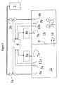
系統図である図1は、本発明の方法の基本的な機能の一例を示すものであって、これに関連する制御および測定のシステムを含む。配管は、ここでは太い線で示され、測定/制御のラインは通常の細い線で示してある。不活性ガスは、不活性ガス源(2)から放出することができ、バルブ(3a)および1個または2個以上の出口ノズル(6a)を通って、保護領域(1a)に至る。不活性ガス源は、このように、多様な設計が可能である。代表的な構成は、不活性ガスを1個または複数の容器、たとえば鋼製の円筒容器から提供する。別のやり方としては、不活性ガス(たとえば窒素)または不活性ガス/空気混合物を製造する、ガス発生器を使用することもできる。一次的なガス源としては、安全性を増大する目的で、余剰な設計をすることも考えられる。すなわち、必要であれば、第二の不活性ガス源を設置することであって、それは鋼製の円筒容器に入れた圧縮不活性ガスであってもよいし、また、不活性ガスを製造するガス発生器であってもよい。 FIG. 1, which is a system diagram, illustrates an example of the basic functions of the method of the present invention and includes the associated control and measurement system. The piping is shown here as a thick line, and the measurement / control line is shown as a normal thin line. The inert gas can be released from the inert gas source (2) and passes through the valve (3a) and one or more outlet nozzles (6a) to the protection area (1a). The inert gas source can thus be designed in various ways. A typical configuration provides the inert gas from one or more containers, such as a steel cylindrical container. Alternatively, a gas generator that produces an inert gas (eg, nitrogen) or an inert gas / air mixture can be used. As a primary gas source, an excessive design may be considered for the purpose of increasing safety. That is, if necessary, a second inert gas source is installed, which may be a compressed inert gas contained in a steel cylindrical container, or produces an inert gas. It may be a gas generator.
保護領域(1a)における不活性ガス濃度は、制御ユニット(4)によって調整され、制御ユニットは、バルブ(3a)を動かす。制御ユニット(4)は、基本の不活性化レベルが保護領域(1a)において達成されるように設定される。この基本の不活性化レベルは、保護領域(1a)における火災または爆発の危険を減少させるものであって、不活性ガスを、不活性ガス源(2)からバルブ(3a)および不活性ガス入口ノズル(6a)を通じて、保護領域(1a)内に導入することにより維持される。このシステムの構成が作動しない場合、たとえばバルブ(3a)が閉鎖しないか、または不活性ガスまたは不活性ガス/空気混合物を製造する発生器がスイッチ・オフせず、そのために不活性ガスが不活性ガス入口(6a)を通じて連続的に保護領域に入ることを許し、そのために保護領域における不活性ガス濃度が連続的に上昇して、酸素濃度が所望する基本の不活性化レベルをはるかに超えて低くなるような場合、下記のような本発明のメカニズムが作動する。 The inert gas concentration in the protection area (1a) is adjusted by the control unit (4), which moves the valve (3a). The control unit (4) is set so that a basic deactivation level is achieved in the protection area (1a). This basic deactivation level is to reduce the risk of fire or explosion in the protected area (1a), from the inert gas source (2) to the valve (3a) and the inert gas inlet. It is maintained by introducing it into the protection area (1a) through the nozzle (6a). If this system configuration does not work, for example, the valve (3a) does not close or the generator producing the inert gas or inert gas / air mixture does not switch off, so that the inert gas is inert. Permits continuous entry into the protection zone through the gas inlet (6a), so that the inert gas concentration in the protection zone increases continuously, so that the oxygen concentration far exceeds the desired basic deactivation level. In the case of lowering, the mechanism of the present invention operates as follows.
酸素センサー(5a)により制御ユニット(4)が測定していた酸素濃度があまりに低くなったときは、それに応じて、バルブ(3a)を閉鎖する信号、または不活性ガスまたは不活性ガス/空気混合物を製造していた発生器を停止させる信号を発する。ひとたびこれら二つの条件が合致し、保護領域(1a)における酸素濃度がさらに低下したならば、そのことは、不活性ガスセンサー(12a)により制御ユニット(4)に対して通知され、新鮮な空気を供給するシステム(8a)が稼動し、追加の新鮮な空気を、保護領域(1a)内に、1個または複数個の新鮮な空気の供給入口(7a)を通じて放出する。 When the oxygen concentration measured by the control unit (4) by the oxygen sensor (5a) becomes too low, a signal to close the valve (3a) or an inert gas or inert gas / air mixture accordingly. A signal to stop the generator that manufactured the Once these two conditions are met and the oxygen concentration in the protected area (1a) further decreases, this is notified to the control unit (4) by the inert gas sensor (12a) and fresh air System (8a) is activated and additional fresh air is discharged into the protection area (1a) through one or more fresh air supply inlets (7a).
流入する新鮮な空気の量は、不活性ガス製造システム(ガス容器またはガス発生器のどちらを設けた場合でも)が最大限の稼動をしているとき、保護領域(1a)における不活性ガス濃度は、上昇を続けることができないように設定する。それゆえ、これによって、保護領域(1a)への不活性ガスの流入を制御する制御ユニットが機能しなくなった場合でも、保護領域(1a)における所望の酸素濃度が確保される。このようにして、火災は信頼をもって防止され、必要であれば、人々は依然として保護領域(1a)内に止まることができ、それ以上の影響をおそれる必要はない。 The amount of fresh air flowing in is determined by the inert gas concentration in the protected area (1a) when the inert gas production system (whether equipped with a gas container or gas generator) is operating at its maximum. Set so that it cannot continue to climb. Therefore, this ensures a desired oxygen concentration in the protection region (1a) even when the control unit for controlling the inflow of the inert gas to the protection region (1a) fails. In this way, fires are reliably prevented and, if necessary, people can still remain in the protected area (1a) and do not have to fear further effects.
図2は、保護領域(1a)における酸素濃度の、実行可能なシーケンスの一例を示す図である。酸素濃度は、実際上、目的とする値の上限と下限の間にある、基本の不活性化レベル(目的とする値)に調整しておく。不活性ガス源が稼動し、不活性ガスが、時点(t0)において保護領域(1a)内に導入される。この不活性ガスを保護領域(1a)内に導入した結果、酸素濃度は時点(t0)から(t1)の間に低下する。不活性ガス源は、時点(t1)において再度稼動させられる。たとえば周囲からの空気の漏洩に起因して、若干の新鮮な空気が保護領域に入ることにより、酸素濃度は、ゆっくりとふたたび上昇を続け、時点(t2)に至る。 FIG. 2 is a diagram showing an example of an executable sequence of oxygen concentration in the protection region (1a). The oxygen concentration is adjusted to a basic deactivation level (target value) that is practically between the upper limit and the lower limit of the target value. The inert gas source is activated and the inert gas is introduced into the protected area (1a) at time (t 0 ). As a result of introducing this inert gas into the protection region (1a), the oxygen concentration decreases between time (t 0 ) and (t 1 ). The inert gas source is turned on again at time (t 1 ). As a result of some fresh air entering the protected area, for example due to leakage of air from the surroundings, the oxygen concentration slowly rises again and reaches a point in time (t 2 ).
時点(t2)において、不活性ガス源は再度稼動させられる。しかしながら、なんらかの欠陥が不活性ガス源を稼動停止させなかった場合、保護領域において、酸素濃度は低下を続ける。保護領域(1a)に対して許容され、かつ、人々に対してなお安全である最大不活性化濃度に、時点(t3)において到達する。不活性ガスシステムが誤作動した場合、すなわち、保護領域内に、不活性ガスの妨害されない連続した流入があった場合、酸素濃度は時点(t3)を過ぎても低下を続け、それは、保護領域を、人々が居るのに安全ではないものにする。 At the time (t 2 ), the inert gas source is turned on again. However, if any defects do not shut down the inert gas source, the oxygen concentration continues to decrease in the protected area. A maximum inactivation concentration that is permissible for the protected area (1a) and is still safe for people is reached at time (t 3 ). If the inert gas system malfunctions, i.e. if there is an uninterrupted continuous flow of inert gas in the protected area, the oxygen concentration continues to drop past the point in time (t 3 ), which Make the area unsafe for people to live.
本発明に従って、新鮮な空気を制御下に導入することを、時点(t3)から実施することにより、最大不活性化レベルを下回る低下は生じない。すなわち、保護領域における酸素濃度は、最大不活性化レベルよりも高い値に止まる。時点(t3)において作動する、緊急アラーム(図示してない)を設けることもできる。火災を確実に防止することができる基本的な不活性化レベルが、時点(t4)において、再度確保される。火災に対する保護を維持するために、新鮮な空気の供給は、時点(t4)において、再度スイッチ・オフされる。 In accordance with the present invention, the introduction of fresh air under control from the point in time (t 3 ) does not cause a drop below the maximum deactivation level. That is, the oxygen concentration in the protected region remains higher than the maximum deactivation level. It is also possible to provide an emergency alarm (not shown) that is activated at time (t 3 ). A basic deactivation level that can reliably prevent a fire is again ensured at time (t 4 ). In order to maintain protection against fire, the fresh air supply is switched off again at time (t 4 ).
図3は、不活性化システムのさらに別の態様であって、この場合、2個の保護領域(1a)および(1b)と、ゾーンを特定した不活性化部分およびモニター部分とからなるものを示す。保護領域(1a)は、この場合、図1および図2の記述において示した詳細に従う。不活性化部分およびモニター部分をそなえた、さらなる保護領域(1b)について、追加の説明をする。上記の構成部分は、バルブ(3b)、不活性ガス入口(6b)、酸素センサー(5b)、新鮮な空気の入口(7b)および新鮮な空気の供給システム(8b)を包含する。 FIG. 3 shows still another embodiment of the inactivation system, which comprises two protection areas (1a) and (1b), a zone-specific inactivation part and a monitor part. Show. The protection area (1a) in this case follows the details given in the description of FIGS. An additional explanation will be given for the additional protection region (1b) with inactivation and monitoring parts. The above components include a valve (3b), an inert gas inlet (6b), an oxygen sensor (5b), a fresh air inlet (7b) and a fresh air supply system (8b).
別の態様としては、図3に示した制御ユニット(4)を、2個の別々の制御ユニットから構成することもできる。二つの保護領域(1a,1b)は、相互に、壁(9)により分離されている。保護領域(1a)は、人々がこの場合アクセスせず、異なる(より高い)不活性化レベルを有するのに対し、保護領域(1b)には、不活性化にかかわらず、人々が、通常のベースで入ったり出たりする。保護領域(1a)は、酸素濃度が、たとえば13容量%という不活性化レベルを持つことができる。それに対して、制御ユニット(4)は、保護領域(1b)に対しては、たとえば酸素濃度が17容量%という、それと異なる不活性化レベルを保証する。 As another aspect, the control unit (4) shown in FIG. 3 can be composed of two separate control units. The two protection areas (1a, 1b) are separated from each other by a wall (9). The protected area (1a) is not accessed by people in this case and has a different (higher) deactivation level, whereas the protected area (1b) does not allow people to Enter and leave the base. The protection region (1a) can have an inactivation level of oxygen concentration of, for example, 13% by volume. In contrast, the control unit (4) guarantees a different inactivation level for the protection region (1b), for example an oxygen concentration of 17% by volume.
壁(9)が透過性であるため、不活性ガスは保護領域(1a)から保護領域(1b)に向かって、制御できない状況で移動することがある。このことは、図3に、方向を示す矢印(10)で示してある。制御ユニット(4)の機能は、図1を参照して説明したように、保護領域(1a)および(1b)における、異なる不活性化レベルを、バルブ(3a)および(3b)を通じて不活性ガスを供給し、必要に応じて新鮮な空気を、新鮮な空気の供給システム(8a)および(8b)から、新鮮な空気の供給入口(7a)および(7b)を通じて供給することにより、保証することにある。バルブ(3a)および(3b)は、この場合、別々の保護領域(1a)および(1b)が、それぞれ別々にモニターされる領域を構成するので、ゾーン・バルブと呼ばれる。 Since the wall (9) is permeable, the inert gas may move from the protected area (1a) toward the protected area (1b) in an uncontrollable situation. This is indicated in FIG. 3 by a direction arrow (10). The function of the control unit (4) is as described with reference to FIG. And, as necessary, fresh air is assured by supplying fresh air from the fresh air supply systems (8a) and (8b) through the fresh air supply inlets (7a) and (7b). It is in. Valves (3a) and (3b) are in this case called zone valves since the separate protection zones (1a) and (1b) constitute zones that are monitored separately.
1a 第一の保護領域
1b 第二の保護領域
2 不活性ガス源
3a ゾーン・バルブ
3b ゾーン・バルブ
4 制御ユニット
5a 酸素センサー
5b 酸素センサー
6a 不活性ガス入口
6b 不活性ガス入口
7a 新鮮な空気の供給入口
7b 新鮮な空気の供給入口
8a 新鮮な空気の供給システム
8b 新鮮な空気の供給システム
9 分割壁
10 不活性ガスの流れの方向を示す矢印
11 保護領域内の人々
12a 不活性ガスセンサー
12b 不活性ガスセンサー
DESCRIPTION OF SYMBOLS 1a 1st protection area 1b 2nd protection area 2
Claims (10)
保護領域(1a,1b)内の酸素含有量を測定し、しきい値(最大の不活性化レベル)と比較し、それがしきい値(最大の不活性化レベル)を下回った場合には、新鮮な空気を保護領域(1a,1b)に導入することを特徴とする方法。 Reducing the oxygen content in the first closed protected area (1a) and / or the second closed protected area (1b) to a basic deactivation level in relation to the surroundings. A deactivation method for preventing fire or explosion in the protected areas (1a, 1b),
The oxygen content in the protected area (1a, 1b) is measured and compared with a threshold value (maximum deactivation level) and if it falls below the threshold value (maximum deactivation level) A method characterized in that fresh air is introduced into the protected areas (1a, 1b).
酸素濃度のしきい値が、基本の不活性化レベルにおける酸素含有量の値よりも低いことを特徴とする方法。 The method of claim 1, wherein
A method characterized in that the threshold value of oxygen concentration is lower than the value of oxygen content at a basic deactivation level.
保護領域(1a,1b)内の不活性ガス含有量を測定し、しきい値と比較し、それがしきい値を超えるに至ったときには、新鮮な空気を保護領域(1a,1b)に導入することを特徴とする方法。 The method according to claim 1, wherein the oxygen content in the protective region (1a, 1b) is reduced by introduction of an inert gas or an inert gas / air mixture replacing oxygen.
Measure the inert gas content in the protection area (1a, 1b), compare with the threshold value, and when it reaches the threshold value, introduce fresh air into the protection area (1a, 1b) A method characterized by:
保護領域(1a,1b)における酸素含有量を、1箇所または2箇所以上において、それぞれ1個または複数個の酸素センサー(5a,5b)を用いて測定することを特徴とする方法。 The method of claim 1 or 2,
A method of measuring the oxygen content in the protection region (1a, 1b) at one or two or more locations using one or a plurality of oxygen sensors (5a, 5b), respectively.
保護領域(1a,1b)における不活性ガス含有量を、1箇所または2箇所以上において、それぞれ1個または複数個の不活性ガスセンサー(12a,12b)を用いて測定することを特徴とする方法。 The method of claim 3, wherein
A method characterized in that the inert gas content in the protection region (1a, 1b) is measured at one or more locations by using one or a plurality of inert gas sensors (12a, 12b), respectively. .
酸素含有量の測定値、不活性ガス含有量の測定値を、それぞれ制御ユニット(4)に供給することを特徴とする方法。 6. The method of claim 4 or 5,
A method of supplying a measured value of oxygen content and a measured value of inert gas content to the control unit (4), respectively.
制御ユニット(4)は新鮮な空気の供給システム(8a,8b)を、オン/オフにスイッチすることができることを特徴とする方法。 The method of claim 6 wherein:
A method characterized in that the control unit (4) can switch the fresh air supply system (8a, 8b) on / off.
新鮮な空気の供給を、あらかじめ制御することができる最大の不活性化レベルを下回ることなく、かつ、基本の不活性レベルを超えることがないように調節することを特徴とする方法。 In any of the above claims,
A method characterized in that the supply of fresh air is adjusted so that it does not fall below the maximum deactivation level that can be controlled in advance and does not exceed the basic deactivation level.
制御ユニット(4)は、第二の保護領域(1b)を、酸素濃度に関して、新鮮な空気のシステム(8b)、少なくとも一つの酸素センサー(5b)、少なくとも一つの不活性ガスセンサー(12b)、ゾーン・バルブ(3b)、不活性ガス入口(6b)および新鮮な空気の入口(7b)を用いてモニターし、最大の不活性化レベルを下回ることなく、かつ、基本の不活性化レベルを超えないようにすることを特徴とする方法。 A method according to any of claims 6 to 8,
The control unit (4) has a second protected area (1b) with regard to oxygen concentration, a fresh air system (8b), at least one oxygen sensor (5b), at least one inert gas sensor (12b), Monitored with zone valve (3b), inert gas inlet (6b) and fresh air inlet (7b), without exceeding the maximum deactivation level and exceeding the basic deactivation level A method characterized by not having.
制御ユニット(4)は、保護領域(1a,1b)における酸素濃度を、最大の不活性化レベルにおいて、前記酸素濃度が第二の保護領域(1b)において、第一の保護領域(1a)におけるよりも高くなるように調節することを特徴とする方法。 The method of claim 9, wherein
The control unit (4) sets the oxygen concentration in the protection region (1a, 1b) at the maximum deactivation level, and the oxygen concentration is in the second protection region (1b) and in the first protection region (1a). A method characterized by adjusting the height to be higher.
Applications Claiming Priority (2)
| Application Number | Priority Date | Filing Date | Title |
|---|---|---|---|
| EP05001224A EP1683548B1 (en) | 2005-01-21 | 2005-01-21 | Inerting method for avoiding fire |
| PCT/EP2005/011773 WO2006076936A1 (en) | 2005-01-21 | 2005-11-03 | Inertization method for avoiding fires |
Publications (1)
| Publication Number | Publication Date |
|---|---|
| JP2008528073A true JP2008528073A (en) | 2008-07-31 |
Family
ID=34933401
Family Applications (1)
| Application Number | Title | Priority Date | Filing Date |
|---|---|---|---|
| JP2007551550A Pending JP2008528073A (en) | 2005-01-21 | 2005-11-03 | Deactivation method for fire prevention |
Country Status (17)
| Country | Link |
|---|---|
| US (1) | US8517116B2 (en) |
| EP (1) | EP1683548B1 (en) |
| JP (1) | JP2008528073A (en) |
| KR (1) | KR101179786B1 (en) |
| CN (1) | CN101102820A (en) |
| AU (1) | AU2005325609B2 (en) |
| BR (1) | BRPI0519823B1 (en) |
| CA (1) | CA2594663C (en) |
| DK (1) | DK1683548T3 (en) |
| ES (1) | ES2398958T3 (en) |
| HK (1) | HK1091152A1 (en) |
| MX (1) | MX2007008702A (en) |
| NO (1) | NO20074265L (en) |
| PL (1) | PL1683548T3 (en) |
| RU (1) | RU2372954C2 (en) |
| UA (1) | UA91041C2 (en) |
| WO (1) | WO2006076936A1 (en) |
Cited By (2)
| Publication number | Priority date | Publication date | Assignee | Title |
|---|---|---|---|---|
| JP2010511447A (en) * | 2006-12-08 | 2010-04-15 | アムロナ・アーゲー | Method and apparatus for supplying makeup air under control |
| US8517116B2 (en) | 2005-01-21 | 2013-08-27 | Amrona Ag | Inertization method for preventing fires |
Families Citing this family (19)
| Publication number | Priority date | Publication date | Assignee | Title |
|---|---|---|---|---|
| DE102005002172A1 (en) * | 2005-01-17 | 2006-07-27 | Amrona Ag | Inertization process for fire prevention |
| PT1913980E (en) * | 2006-10-19 | 2009-03-19 | Amrona Ag | Inerting device with safety device |
| EP1913979B1 (en) * | 2006-10-19 | 2009-01-14 | Amrona AG | Inerting device with nitrogen generator |
| PT1913978E (en) | 2006-10-19 | 2009-08-31 | Amrona Ag | Inerting device with nitrogen generator |
| EP2173440B1 (en) | 2007-08-01 | 2015-07-22 | Amrona AG | Device and method for fire-prevention and for extinguishing a fire that has broken out in an enclosed area |
| US9526933B2 (en) * | 2008-09-15 | 2016-12-27 | Engineered Corrosion Solutions, Llc | High nitrogen and other inert gas anti-corrosion protection in wet pipe fire protection system |
| NL2006405C2 (en) * | 2011-03-16 | 2012-09-18 | Storex B V | OXYGEN REDUCTION SYSTEM IN A SPACE IN A BUILDING. |
| RU2465512C1 (en) * | 2011-04-19 | 2012-10-27 | Российская Федерация, от имени которой выступает Государственная корпорация по атомной энергии "Росатом" | Device for maintaining air medium composition in sealed container |
| RU2465513C1 (en) * | 2011-04-21 | 2012-10-27 | Российская Федерация, от имени которой выступает Государственная корпорация по атомной энергии "Росатом" | Device for forced gas exchange in sealed container |
| KR101244426B1 (en) | 2012-12-03 | 2013-03-18 | (유)성문 | Apparatus for protecting and repressing fire |
| CN104210667A (en) * | 2014-09-22 | 2014-12-17 | 中国商用飞机有限责任公司 | Inerting system control method and device for monitoring oxygen concentration |
| PL3011999T3 (en) * | 2014-10-24 | 2018-01-31 | Amrona Ag | System and method for reducing the oxygen in a target space |
| EP3111999B1 (en) * | 2015-07-02 | 2017-12-06 | Amrona AG | Oxygen reducing installation and method for dimensioning out an oxygen reducing installation |
| SG11201804790RA (en) * | 2015-12-22 | 2018-07-30 | Amrona Ag | Oxygen Reduction System and Method for Operating an Oxygen Reduction System |
| FR3054795B1 (en) * | 2016-08-03 | 2018-07-20 | Zodiac Aerotechnics | METHOD AND SYSTEM FOR INERTING A FUEL TANK |
| EP3568215B1 (en) * | 2017-01-12 | 2021-09-01 | Fire Eater A/S | A method for inerting a fire |
| EP3569290B1 (en) * | 2018-05-14 | 2024-02-14 | Wagner Group GmbH | Control and regulating system for an oxygen reducing installation |
| CN110807265A (en) * | 2019-11-08 | 2020-02-18 | 重庆科技学院 | Closed fire area combustion explosion risk judgment method based on atmospheric disturbance |
| US20230288298A1 (en) * | 2020-07-14 | 2023-09-14 | Cast Environmental, Llc | Gas Monitoring Systems and Methods |
Citations (4)
| Publication number | Priority date | Publication date | Assignee | Title |
|---|---|---|---|---|
| JPH09276428A (en) * | 1996-04-08 | 1997-10-28 | Sekiko Ryo | Method and system for preventing and distinguishing fire |
| JP2001046536A (en) * | 1999-08-12 | 2001-02-20 | Purosasu:Kk | Suppression method and apparatus for machine fire |
| JP2003071640A (en) * | 2001-08-28 | 2003-03-12 | Matsushita Electric Works Ltd | Extinguishing system of high-precision machining device |
| JP2003102858A (en) * | 2001-09-28 | 2003-04-08 | Nohmi Bosai Ltd | Fire prevention system for closed space |
Family Cites Families (24)
| Publication number | Priority date | Publication date | Assignee | Title |
|---|---|---|---|---|
| GB1385122A (en) | 1972-03-13 | 1975-02-26 | Bridgett C D S | Process for the degassing and cleaning of fuel tanks and tankers and rendering them safe for repair |
| JPS521997A (en) * | 1975-06-16 | 1977-01-08 | Kimimichi Monma | Quick system for extinguishing fire of a multistorey building |
| SU955946A1 (en) | 1981-03-30 | 1982-09-07 | за вители | Method of preventing fire in sealed inhabited sections |
| SU1151246A1 (en) | 1983-03-21 | 1985-04-23 | Испытательная Пожарная Лаборатория Управления Пожарной Охраны Управления Внутренних Дел Алтайского Крайисполкома | Installation for gas fire-fighting |
| US5090482A (en) | 1990-01-03 | 1992-02-25 | Spectronix Ltd. | Method and apparatus for extinguishing fires |
| DE4223781A1 (en) | 1992-07-18 | 1994-01-20 | Bayerische Motoren Werke Ag | Output air filtration method - prevents fire in filter unit and adsorbs harmful material |
| US6314754B1 (en) * | 2000-04-17 | 2001-11-13 | Igor K. Kotliar | Hypoxic fire prevention and fire suppression systems for computer rooms and other human occupied facilities |
| US5799495A (en) * | 1996-10-30 | 1998-09-01 | Nitec, Inc. | Container oxygen control system for transporting and ripening perishable goods |
| JP3832612B2 (en) | 1997-07-16 | 2006-10-11 | 忠弘 大見 | Fire extinguishing method and apparatus in clean room |
| US20020040940A1 (en) * | 1998-03-18 | 2002-04-11 | Wagner Ernst Werner | Inerting method and apparatus for preventing and extinguishing fires in enclosed spaces |
| DE19811851C2 (en) | 1998-03-18 | 2001-01-04 | Wagner Alarm Sicherung | Inerting procedure for fire prevention and extinguishing in closed rooms |
| WO2000052293A2 (en) * | 1999-03-03 | 2000-09-08 | Fmc Corporation | Explosion prevention system for internal turret mooring system |
| JP2003530922A (en) | 2000-04-17 | 2003-10-21 | コトライアー・イガー・ケイ | Low Oxygen Concentration Fire Prevention and Fire Suppression Systems and Respirable Fire Extinguishing Compositions in Manned Environments |
| DE10033650A1 (en) | 2000-07-11 | 2002-01-31 | Messer Griesheim Gmbh | Plant and method for storing and / or processing objects under inert conditions |
| RU2200044C2 (en) | 2000-12-09 | 2003-03-10 | Русаков Валерий Федорович | Method for providing fire-suppressing concentration of inert diluent (versions) |
| DK1261396T3 (en) | 2001-01-11 | 2006-08-21 | Wagner Alarm Sicherung | Method of inertization with nitrogen buffer |
| GB2374007A (en) | 2001-04-04 | 2002-10-09 | Kidde Plc | Fire / explosion protection system and method, using inert gas produced in low temperature catalytic oxidation of organic fuel |
| US6871645B2 (en) * | 2001-09-14 | 2005-03-29 | The United States Of America As Represented By The Secretary Of The Navy | Reduced-oxygen breathing device |
| DE10156042A1 (en) * | 2001-11-15 | 2003-05-28 | Wagner Alarm Sicherung | Method and device for extinguishing fires in tunnels |
| DE10164293A1 (en) * | 2001-12-28 | 2003-07-10 | Wagner Alarm Sicherung | Method and device for measuring the oxygen content |
| GB2397821B (en) * | 2003-01-30 | 2006-04-05 | Smartmembrane Corp | Oxygen and nitrogen enriched atmospheres in aircraft |
| DE10310439B3 (en) * | 2003-03-11 | 2004-12-09 | Basf Coatings Ag | Process for fire and explosion protection in a high-bay warehouse for chemical hazardous substances and fire and explosion-protected high-bay warehouse |
| ITMI20030925A1 (en) * | 2003-05-08 | 2004-11-09 | Vesta Srl Ora Gastec Vesta Srl | INERT GAS FIRE FIGHTING SYSTEM AND RELATED METHOD FOR THE FIRE EXTINGUISHING |
| EP1683548B1 (en) | 2005-01-21 | 2012-12-12 | Amrona AG | Inerting method for avoiding fire |
-
2005
- 2005-01-21 EP EP05001224A patent/EP1683548B1/en active Active
- 2005-01-21 PL PL05001224T patent/PL1683548T3/en unknown
- 2005-01-21 ES ES05001224T patent/ES2398958T3/en active Active
- 2005-01-21 DK DK05001224.4T patent/DK1683548T3/en active
- 2005-11-03 JP JP2007551550A patent/JP2008528073A/en active Pending
- 2005-11-03 MX MX2007008702A patent/MX2007008702A/en active IP Right Grant
- 2005-11-03 AU AU2005325609A patent/AU2005325609B2/en not_active Ceased
- 2005-11-03 CA CA2594663A patent/CA2594663C/en not_active Expired - Fee Related
- 2005-11-03 BR BRPI0519823A patent/BRPI0519823B1/en not_active IP Right Cessation
- 2005-11-03 UA UAA200708372A patent/UA91041C2/en unknown
- 2005-11-03 RU RU2007131661/12A patent/RU2372954C2/en not_active IP Right Cessation
- 2005-11-03 WO PCT/EP2005/011773 patent/WO2006076936A1/en active Application Filing
- 2005-11-03 US US11/795,798 patent/US8517116B2/en active Active
- 2005-11-03 CN CNA2005800467253A patent/CN101102820A/en active Pending
-
2006
- 2006-10-25 HK HK06111778.9A patent/HK1091152A1/en not_active IP Right Cessation
-
2007
- 2007-07-11 KR KR1020077015831A patent/KR101179786B1/en not_active IP Right Cessation
- 2007-08-21 NO NO20074265A patent/NO20074265L/en not_active Application Discontinuation
Patent Citations (4)
| Publication number | Priority date | Publication date | Assignee | Title |
|---|---|---|---|---|
| JPH09276428A (en) * | 1996-04-08 | 1997-10-28 | Sekiko Ryo | Method and system for preventing and distinguishing fire |
| JP2001046536A (en) * | 1999-08-12 | 2001-02-20 | Purosasu:Kk | Suppression method and apparatus for machine fire |
| JP2003071640A (en) * | 2001-08-28 | 2003-03-12 | Matsushita Electric Works Ltd | Extinguishing system of high-precision machining device |
| JP2003102858A (en) * | 2001-09-28 | 2003-04-08 | Nohmi Bosai Ltd | Fire prevention system for closed space |
Cited By (3)
| Publication number | Priority date | Publication date | Assignee | Title |
|---|---|---|---|---|
| US8517116B2 (en) | 2005-01-21 | 2013-08-27 | Amrona Ag | Inertization method for preventing fires |
| JP2010511447A (en) * | 2006-12-08 | 2010-04-15 | アムロナ・アーゲー | Method and apparatus for supplying makeup air under control |
| JP4883184B2 (en) * | 2006-12-08 | 2012-02-22 | アムロナ・アーゲー | Method and apparatus for supplying makeup air under control |
Also Published As
| Publication number | Publication date |
|---|---|
| HK1091152A1 (en) | 2007-01-12 |
| EP1683548A1 (en) | 2006-07-26 |
| MX2007008702A (en) | 2007-10-23 |
| NO20074265L (en) | 2007-08-21 |
| EP1683548B1 (en) | 2012-12-12 |
| US8517116B2 (en) | 2013-08-27 |
| US20080196907A1 (en) | 2008-08-21 |
| RU2007131661A (en) | 2009-02-27 |
| KR101179786B1 (en) | 2012-09-04 |
| KR20070102511A (en) | 2007-10-18 |
| BRPI0519823A2 (en) | 2009-03-24 |
| RU2372954C2 (en) | 2009-11-20 |
| WO2006076936A1 (en) | 2006-07-27 |
| AU2005325609B2 (en) | 2011-02-10 |
| CA2594663C (en) | 2014-01-07 |
| UA91041C2 (en) | 2010-06-25 |
| AU2005325609A1 (en) | 2006-07-27 |
| CN101102820A (en) | 2008-01-09 |
| ES2398958T3 (en) | 2013-03-22 |
| DK1683548T3 (en) | 2013-02-11 |
| BRPI0519823B1 (en) | 2016-06-14 |
| CA2594663A1 (en) | 2006-07-27 |
| PL1683548T3 (en) | 2013-04-30 |
Similar Documents
| Publication | Publication Date | Title |
|---|---|---|
| JP2008528073A (en) | Deactivation method for fire prevention | |
| JP5021750B2 (en) | Inactivation device with safety mechanism | |
| CA2594796C (en) | Inerting method for preventing fires | |
| US10052509B2 (en) | Method for extinguishing a fire in an enclosed space, and fire extinguishing system | |
| US20170014655A1 (en) | Aircraft with fire suppression control system | |
| US9220937B2 (en) | Inerting method and device for extinguishing a fire | |
| CA2551226C (en) | Inertisation method for reducing the risk of fire | |
| DK2322251T3 (en) | A method of operating a fire-extinguishing system |
Legal Events
| Date | Code | Title | Description |
|---|---|---|---|
| A621 | Written request for application examination |
Free format text: JAPANESE INTERMEDIATE CODE: A621 Effective date: 20080521 |
|
| A131 | Notification of reasons for refusal |
Free format text: JAPANESE INTERMEDIATE CODE: A131 Effective date: 20100810 |
|
| A601 | Written request for extension of time |
Free format text: JAPANESE INTERMEDIATE CODE: A601 Effective date: 20101108 |
|
| A602 | Written permission of extension of time |
Free format text: JAPANESE INTERMEDIATE CODE: A602 Effective date: 20101115 |
|
| A601 | Written request for extension of time |
Free format text: JAPANESE INTERMEDIATE CODE: A601 Effective date: 20101208 |
|
| A602 | Written permission of extension of time |
Free format text: JAPANESE INTERMEDIATE CODE: A602 Effective date: 20101215 |
|
| A521 | Request for written amendment filed |
Free format text: JAPANESE INTERMEDIATE CODE: A523 Effective date: 20101229 |
|
| A131 | Notification of reasons for refusal |
Free format text: JAPANESE INTERMEDIATE CODE: A131 Effective date: 20110208 |
|
| A601 | Written request for extension of time |
Free format text: JAPANESE INTERMEDIATE CODE: A601 Effective date: 20110506 |
|
| A602 | Written permission of extension of time |
Free format text: JAPANESE INTERMEDIATE CODE: A602 Effective date: 20110513 |
|
| A601 | Written request for extension of time |
Free format text: JAPANESE INTERMEDIATE CODE: A601 Effective date: 20110607 |
|
| A602 | Written permission of extension of time |
Free format text: JAPANESE INTERMEDIATE CODE: A602 Effective date: 20110614 |
|
| A521 | Request for written amendment filed |
Free format text: JAPANESE INTERMEDIATE CODE: A523 Effective date: 20110708 |
|
| A02 | Decision of refusal |
Free format text: JAPANESE INTERMEDIATE CODE: A02 Effective date: 20110913 |