JP2008524403A - Method for forming a patterned fluoropolymer film on a substrate - Google Patents
Method for forming a patterned fluoropolymer film on a substrate Download PDFInfo
- Publication number
- JP2008524403A JP2008524403A JP2007547035A JP2007547035A JP2008524403A JP 2008524403 A JP2008524403 A JP 2008524403A JP 2007547035 A JP2007547035 A JP 2007547035A JP 2007547035 A JP2007547035 A JP 2007547035A JP 2008524403 A JP2008524403 A JP 2008524403A
- Authority
- JP
- Japan
- Prior art keywords
- fluoropolymer
- film
- substrate
- printing
- patterned
- Prior art date
- Legal status (The legal status is an assumption and is not a legal conclusion. Google has not performed a legal analysis and makes no representation as to the accuracy of the status listed.)
- Withdrawn
Links
- 229920002313 fluoropolymer Polymers 0.000 title claims abstract description 96
- 239000004811 fluoropolymer Substances 0.000 title claims abstract description 96
- 239000000758 substrate Substances 0.000 title claims abstract description 65
- 238000000034 method Methods 0.000 title claims abstract description 53
- 238000007639 printing Methods 0.000 claims abstract description 66
- 239000002904 solvent Substances 0.000 claims abstract description 24
- 238000001035 drying Methods 0.000 claims abstract description 18
- 230000003667 anti-reflective effect Effects 0.000 claims abstract description 14
- 239000002318 adhesion promoter Substances 0.000 claims description 16
- -1 polyethylene terephthalate Polymers 0.000 claims description 9
- 229920000139 polyethylene terephthalate Polymers 0.000 claims description 8
- 239000005020 polyethylene terephthalate Substances 0.000 claims description 8
- 229920002284 Cellulose triacetate Polymers 0.000 claims description 6
- NNLVGZFZQQXQNW-ADJNRHBOSA-N [(2r,3r,4s,5r,6s)-4,5-diacetyloxy-3-[(2s,3r,4s,5r,6r)-3,4,5-triacetyloxy-6-(acetyloxymethyl)oxan-2-yl]oxy-6-[(2r,3r,4s,5r,6s)-4,5,6-triacetyloxy-2-(acetyloxymethyl)oxan-3-yl]oxyoxan-2-yl]methyl acetate Chemical compound O([C@@H]1O[C@@H]([C@H]([C@H](OC(C)=O)[C@H]1OC(C)=O)O[C@H]1[C@@H]([C@@H](OC(C)=O)[C@H](OC(C)=O)[C@@H](COC(C)=O)O1)OC(C)=O)COC(=O)C)[C@@H]1[C@@H](COC(C)=O)O[C@@H](OC(C)=O)[C@H](OC(C)=O)[C@H]1OC(C)=O NNLVGZFZQQXQNW-ADJNRHBOSA-N 0.000 claims description 6
- 229920001577 copolymer Polymers 0.000 claims description 6
- 239000000178 monomer Substances 0.000 claims description 6
- 125000005010 perfluoroalkyl group Chemical group 0.000 claims description 6
- BFKJFAAPBSQJPD-UHFFFAOYSA-N tetrafluoroethene Chemical group FC(F)=C(F)F BFKJFAAPBSQJPD-UHFFFAOYSA-N 0.000 claims description 6
- YSYRISKCBOPJRG-UHFFFAOYSA-N 4,5-difluoro-2,2-bis(trifluoromethyl)-1,3-dioxole Chemical compound FC1=C(F)OC(C(F)(F)F)(C(F)(F)F)O1 YSYRISKCBOPJRG-UHFFFAOYSA-N 0.000 claims description 5
- 229920000642 polymer Polymers 0.000 claims description 5
- 125000004432 carbon atom Chemical group C* 0.000 claims description 4
- 239000011521 glass Substances 0.000 claims description 4
- 125000001153 fluoro group Chemical group F* 0.000 claims description 3
- HCDGVLDPFQMKDK-UHFFFAOYSA-N hexafluoropropylene Chemical group FC(F)=C(F)C(F)(F)F HCDGVLDPFQMKDK-UHFFFAOYSA-N 0.000 claims description 3
- 229920003229 poly(methyl methacrylate) Polymers 0.000 claims description 3
- 229920000058 polyacrylate Polymers 0.000 claims description 3
- 229920000728 polyester Polymers 0.000 claims description 3
- 239000004926 polymethyl methacrylate Substances 0.000 claims description 3
- 125000004178 (C1-C4) alkyl group Chemical group 0.000 claims description 2
- MIZLGWKEZAPEFJ-UHFFFAOYSA-N 1,1,2-trifluoroethene Chemical group FC=C(F)F MIZLGWKEZAPEFJ-UHFFFAOYSA-N 0.000 claims description 2
- BQCIDUSAKPWEOX-UHFFFAOYSA-N 1,1-Difluoroethene Chemical compound FC(F)=C BQCIDUSAKPWEOX-UHFFFAOYSA-N 0.000 claims description 2
- JMGNVALALWCTLC-UHFFFAOYSA-N 1-fluoro-2-(2-fluoroethenoxy)ethene Chemical compound FC=COC=CF JMGNVALALWCTLC-UHFFFAOYSA-N 0.000 claims description 2
- RFJVDJWCXSPUBY-UHFFFAOYSA-N 2-(difluoromethylidene)-4,4,5-trifluoro-5-(trifluoromethyl)-1,3-dioxolane Chemical compound FC(F)=C1OC(F)(F)C(F)(C(F)(F)F)O1 RFJVDJWCXSPUBY-UHFFFAOYSA-N 0.000 claims description 2
- VGGSQFUCUMXWEO-UHFFFAOYSA-N Ethene Chemical compound C=C VGGSQFUCUMXWEO-UHFFFAOYSA-N 0.000 claims description 2
- 239000005977 Ethylene Substances 0.000 claims description 2
- 239000004952 Polyamide Substances 0.000 claims description 2
- 239000004793 Polystyrene Substances 0.000 claims description 2
- 239000004372 Polyvinyl alcohol Substances 0.000 claims description 2
- 125000002947 alkylene group Chemical group 0.000 claims description 2
- 229910052799 carbon Inorganic materials 0.000 claims description 2
- 229920002678 cellulose Polymers 0.000 claims description 2
- 239000001913 cellulose Substances 0.000 claims description 2
- UUAGAQFQZIEFAH-UHFFFAOYSA-N chlorotrifluoroethylene Chemical group FC(F)=C(F)Cl UUAGAQFQZIEFAH-UHFFFAOYSA-N 0.000 claims description 2
- RTZKZFJDLAIYFH-UHFFFAOYSA-N ether Substances CCOCC RTZKZFJDLAIYFH-UHFFFAOYSA-N 0.000 claims description 2
- XUCNUKMRBVNAPB-UHFFFAOYSA-N fluoroethene Chemical compound FC=C XUCNUKMRBVNAPB-UHFFFAOYSA-N 0.000 claims description 2
- 125000004430 oxygen atom Chemical group O* 0.000 claims description 2
- 229920002647 polyamide Polymers 0.000 claims description 2
- 229920000515 polycarbonate Polymers 0.000 claims description 2
- 239000004417 polycarbonate Substances 0.000 claims description 2
- 229920002223 polystyrene Polymers 0.000 claims description 2
- 229920002451 polyvinyl alcohol Polymers 0.000 claims description 2
- 239000004800 polyvinyl chloride Substances 0.000 claims description 2
- 229920000915 polyvinyl chloride Polymers 0.000 claims description 2
- 230000003287 optical effect Effects 0.000 abstract description 8
- 230000002209 hydrophobic effect Effects 0.000 abstract 1
- 239000010408 film Substances 0.000 description 61
- 239000010410 layer Substances 0.000 description 39
- 238000000576 coating method Methods 0.000 description 23
- 239000011248 coating agent Substances 0.000 description 20
- 239000000203 mixture Substances 0.000 description 14
- 239000002245 particle Substances 0.000 description 11
- 238000007774 anilox coating Methods 0.000 description 8
- 239000011230 binding agent Substances 0.000 description 8
- 229910052809 inorganic oxide Inorganic materials 0.000 description 8
- 229920006362 Teflon® Polymers 0.000 description 7
- 239000011347 resin Substances 0.000 description 6
- 229920005989 resin Polymers 0.000 description 6
- VYPSYNLAJGMNEJ-UHFFFAOYSA-N Silicium dioxide Chemical compound O=[Si]=O VYPSYNLAJGMNEJ-UHFFFAOYSA-N 0.000 description 5
- 239000004809 Teflon Substances 0.000 description 5
- 239000007788 liquid Substances 0.000 description 5
- 239000000463 material Substances 0.000 description 5
- 238000005299 abrasion Methods 0.000 description 4
- 239000006117 anti-reflective coating Substances 0.000 description 4
- 239000008199 coating composition Substances 0.000 description 4
- 125000000524 functional group Chemical group 0.000 description 4
- YVBBRRALBYAZBM-UHFFFAOYSA-N perfluorooctane Chemical compound FC(F)(F)C(F)(F)C(F)(F)C(F)(F)C(F)(F)C(F)(F)C(F)(F)C(F)(F)F YVBBRRALBYAZBM-UHFFFAOYSA-N 0.000 description 4
- 229910000077 silane Inorganic materials 0.000 description 4
- NKAMGQZDVMQEJL-UHFFFAOYSA-N 3,3,4,4,5,5,6,6,7,7,8,8,9,9,10,10,10-heptadecafluorodec-1-ene Chemical group FC(F)(F)C(F)(F)C(F)(F)C(F)(F)C(F)(F)C(F)(F)C(F)(F)C(F)(F)C=C NKAMGQZDVMQEJL-UHFFFAOYSA-N 0.000 description 3
- NIXOWILDQLNWCW-UHFFFAOYSA-M Acrylate Chemical compound [O-]C(=O)C=C NIXOWILDQLNWCW-UHFFFAOYSA-M 0.000 description 3
- 229920002799 BoPET Polymers 0.000 description 3
- BLRPTPMANUNPDV-UHFFFAOYSA-N Silane Chemical compound [SiH4] BLRPTPMANUNPDV-UHFFFAOYSA-N 0.000 description 3
- 239000008119 colloidal silica Substances 0.000 description 3
- 238000010924 continuous production Methods 0.000 description 3
- 238000009826 distribution Methods 0.000 description 3
- 238000005516 engineering process Methods 0.000 description 3
- RIQRGMUSBYGDBL-UHFFFAOYSA-N 1,1,1,2,2,3,4,5,5,5-decafluoropentane Chemical compound FC(F)(F)C(F)C(F)C(F)(F)C(F)(F)F RIQRGMUSBYGDBL-UHFFFAOYSA-N 0.000 description 2
- UQSXHKLRYXJYBZ-UHFFFAOYSA-N Iron oxide Chemical compound [Fe]=O UQSXHKLRYXJYBZ-UHFFFAOYSA-N 0.000 description 2
- 239000005041 Mylar™ Substances 0.000 description 2
- 229920001774 Perfluoroether Polymers 0.000 description 2
- GWEVSGVZZGPLCZ-UHFFFAOYSA-N Titan oxide Chemical compound O=[Ti]=O GWEVSGVZZGPLCZ-UHFFFAOYSA-N 0.000 description 2
- MCMNRKCIXSYSNV-UHFFFAOYSA-N Zirconium dioxide Chemical compound O=[Zr]=O MCMNRKCIXSYSNV-UHFFFAOYSA-N 0.000 description 2
- NIXOWILDQLNWCW-UHFFFAOYSA-N acrylic acid group Chemical group C(C=C)(=O)O NIXOWILDQLNWCW-UHFFFAOYSA-N 0.000 description 2
- 230000015572 biosynthetic process Effects 0.000 description 2
- 239000003054 catalyst Substances 0.000 description 2
- 210000004027 cell Anatomy 0.000 description 2
- 239000003795 chemical substances by application Substances 0.000 description 2
- 239000006184 cosolvent Substances 0.000 description 2
- 238000001723 curing Methods 0.000 description 2
- 239000000975 dye Substances 0.000 description 2
- 238000007756 gravure coating Methods 0.000 description 2
- ZQBFAOFFOQMSGJ-UHFFFAOYSA-N hexafluorobenzene Chemical compound FC1=C(F)C(F)=C(F)C(F)=C1F ZQBFAOFFOQMSGJ-UHFFFAOYSA-N 0.000 description 2
- 239000003112 inhibitor Substances 0.000 description 2
- 239000003999 initiator Substances 0.000 description 2
- 239000010954 inorganic particle Substances 0.000 description 2
- 238000007644 letterpress printing Methods 0.000 description 2
- 239000012528 membrane Substances 0.000 description 2
- 238000001556 precipitation Methods 0.000 description 2
- 239000002243 precursor Substances 0.000 description 2
- 238000000985 reflectance spectrum Methods 0.000 description 2
- 239000007787 solid Substances 0.000 description 2
- 125000001424 substituent group Chemical group 0.000 description 2
- AJDIZQLSFPQPEY-UHFFFAOYSA-N 1,1,2-Trichlorotrifluoroethane Chemical compound FC(F)(Cl)C(F)(Cl)Cl AJDIZQLSFPQPEY-UHFFFAOYSA-N 0.000 description 1
- JDCMOHAFGDQQJX-UHFFFAOYSA-N 1,2,3,4,5,6,7,8-octafluoronaphthalene Chemical compound FC1=C(F)C(F)=C(F)C2=C(F)C(F)=C(F)C(F)=C21 JDCMOHAFGDQQJX-UHFFFAOYSA-N 0.000 description 1
- MYWOJODOMFBVCB-UHFFFAOYSA-N 1,2,6-trimethylphenanthrene Chemical compound CC1=CC=C2C3=CC(C)=CC=C3C=CC2=C1C MYWOJODOMFBVCB-UHFFFAOYSA-N 0.000 description 1
- SMZOUWXMTYCWNB-UHFFFAOYSA-N 2-(2-methoxy-5-methylphenyl)ethanamine Chemical compound COC1=CC=C(C)C=C1CCN SMZOUWXMTYCWNB-UHFFFAOYSA-N 0.000 description 1
- 125000000022 2-aminoethyl group Chemical group [H]C([*])([H])C([H])([H])N([H])[H] 0.000 description 1
- SJECZPVISLOESU-UHFFFAOYSA-N 3-trimethoxysilylpropan-1-amine Chemical compound CO[Si](OC)(OC)CCCN SJECZPVISLOESU-UHFFFAOYSA-N 0.000 description 1
- 229920001747 Cellulose diacetate Polymers 0.000 description 1
- 239000004971 Cross linker Substances 0.000 description 1
- XUIMIQQOPSSXEZ-UHFFFAOYSA-N Silicon Chemical group [Si] XUIMIQQOPSSXEZ-UHFFFAOYSA-N 0.000 description 1
- HVVWZTWDBSEWIH-UHFFFAOYSA-N [2-(hydroxymethyl)-3-prop-2-enoyloxy-2-(prop-2-enoyloxymethyl)propyl] prop-2-enoate Chemical compound C=CC(=O)OCC(CO)(COC(=O)C=C)COC(=O)C=C HVVWZTWDBSEWIH-UHFFFAOYSA-N 0.000 description 1
- RMKZLFMHXZAGTM-UHFFFAOYSA-N [dimethoxy(propyl)silyl]oxymethyl prop-2-enoate Chemical compound CCC[Si](OC)(OC)OCOC(=O)C=C RMKZLFMHXZAGTM-UHFFFAOYSA-N 0.000 description 1
- 239000002250 absorbent Substances 0.000 description 1
- 230000002745 absorbent Effects 0.000 description 1
- 125000003668 acetyloxy group Chemical group [H]C([H])([H])C(=O)O[*] 0.000 description 1
- 239000002671 adjuvant Substances 0.000 description 1
- 238000005054 agglomeration Methods 0.000 description 1
- 230000002776 aggregation Effects 0.000 description 1
- 150000001298 alcohols Chemical class 0.000 description 1
- PNEYBMLMFCGWSK-UHFFFAOYSA-N aluminium oxide Inorganic materials [O-2].[O-2].[O-2].[Al+3].[Al+3] PNEYBMLMFCGWSK-UHFFFAOYSA-N 0.000 description 1
- 150000001408 amides Chemical class 0.000 description 1
- 229910000410 antimony oxide Inorganic materials 0.000 description 1
- 239000003963 antioxidant agent Substances 0.000 description 1
- 239000002216 antistatic agent Substances 0.000 description 1
- QVGXLLKOCUKJST-UHFFFAOYSA-N atomic oxygen Chemical compound [O] QVGXLLKOCUKJST-UHFFFAOYSA-N 0.000 description 1
- 238000009835 boiling Methods 0.000 description 1
- 239000003086 colorant Substances 0.000 description 1
- 150000001875 compounds Chemical class 0.000 description 1
- 230000006835 compression Effects 0.000 description 1
- 238000007906 compression Methods 0.000 description 1
- 229920001940 conductive polymer Polymers 0.000 description 1
- 239000003431 cross linking reagent Substances 0.000 description 1
- 230000001419 dependent effect Effects 0.000 description 1
- QDOXWKRWXJOMAK-UHFFFAOYSA-N dichromium trioxide Chemical compound O=[Cr]O[Cr]=O QDOXWKRWXJOMAK-UHFFFAOYSA-N 0.000 description 1
- 238000007598 dipping method Methods 0.000 description 1
- 239000006185 dispersion Substances 0.000 description 1
- 238000010894 electron beam technology Methods 0.000 description 1
- 150000002148 esters Chemical class 0.000 description 1
- 150000002170 ethers Chemical class 0.000 description 1
- 125000001301 ethoxy group Chemical group [H]C([H])([H])C([H])([H])O* 0.000 description 1
- 238000007765 extrusion coating Methods 0.000 description 1
- 239000000945 filler Substances 0.000 description 1
- ZYMKZMDQUPCXRP-UHFFFAOYSA-N fluoro prop-2-enoate Chemical compound FOC(=O)C=C ZYMKZMDQUPCXRP-UHFFFAOYSA-N 0.000 description 1
- 238000001879 gelation Methods 0.000 description 1
- 238000010438 heat treatment Methods 0.000 description 1
- 229930195733 hydrocarbon Natural products 0.000 description 1
- 150000002430 hydrocarbons Chemical class 0.000 description 1
- 238000003384 imaging method Methods 0.000 description 1
- 238000011065 in-situ storage Methods 0.000 description 1
- 239000011256 inorganic filler Substances 0.000 description 1
- 229910003475 inorganic filler Inorganic materials 0.000 description 1
- 238000009434 installation Methods 0.000 description 1
- 230000005865 ionizing radiation Effects 0.000 description 1
- 230000001788 irregular Effects 0.000 description 1
- 239000004973 liquid crystal related substance Substances 0.000 description 1
- 239000000314 lubricant Substances 0.000 description 1
- 239000011159 matrix material Substances 0.000 description 1
- 125000000956 methoxy group Chemical group [H]C([H])([H])O* 0.000 description 1
- 238000002156 mixing Methods 0.000 description 1
- 238000000465 moulding Methods 0.000 description 1
- VTRUBDSFZJNXHI-UHFFFAOYSA-N oxoantimony Chemical compound [Sb]=O VTRUBDSFZJNXHI-UHFFFAOYSA-N 0.000 description 1
- 229910052760 oxygen Inorganic materials 0.000 description 1
- 239000001301 oxygen Substances 0.000 description 1
- 238000004806 packaging method and process Methods 0.000 description 1
- RVZRBWKZFJCCIB-UHFFFAOYSA-N perfluorotributylamine Chemical compound FC(F)(F)C(F)(F)C(F)(F)C(F)(F)N(C(F)(F)C(F)(F)C(F)(F)C(F)(F)F)C(F)(F)C(F)(F)C(F)(F)C(F)(F)F RVZRBWKZFJCCIB-UHFFFAOYSA-N 0.000 description 1
- 239000003504 photosensitizing agent Substances 0.000 description 1
- 239000000049 pigment Substances 0.000 description 1
- 239000004014 plasticizer Substances 0.000 description 1
- 229920006254 polymer film Polymers 0.000 description 1
- 238000006116 polymerization reaction Methods 0.000 description 1
- 230000005855 radiation Effects 0.000 description 1
- 150000003254 radicals Chemical class 0.000 description 1
- 238000002310 reflectometry Methods 0.000 description 1
- 230000003678 scratch resistant effect Effects 0.000 description 1
- 229910052710 silicon Inorganic materials 0.000 description 1
- 239000000377 silicon dioxide Substances 0.000 description 1
- 239000002356 single layer Substances 0.000 description 1
- 239000011877 solvent mixture Substances 0.000 description 1
- 239000007921 spray Substances 0.000 description 1
- 239000003381 stabilizer Substances 0.000 description 1
- 239000000126 substance Substances 0.000 description 1
- 239000012756 surface treatment agent Substances 0.000 description 1
- 239000004094 surface-active agent Substances 0.000 description 1
- 229920001187 thermosetting polymer Polymers 0.000 description 1
- 239000010409 thin film Substances 0.000 description 1
- XOLBLPGZBRYERU-UHFFFAOYSA-N tin dioxide Chemical compound O=[Sn]=O XOLBLPGZBRYERU-UHFFFAOYSA-N 0.000 description 1
- 229910001887 tin oxide Inorganic materials 0.000 description 1
- 239000006097 ultraviolet radiation absorber Substances 0.000 description 1
- 239000002699 waste material Substances 0.000 description 1
- 238000009736 wetting Methods 0.000 description 1
Images
Classifications
-
- B—PERFORMING OPERATIONS; TRANSPORTING
- B41—PRINTING; LINING MACHINES; TYPEWRITERS; STAMPS
- B41M—PRINTING, DUPLICATING, MARKING, OR COPYING PROCESSES; COLOUR PRINTING
- B41M1/00—Inking and printing with a printer's forme
- B41M1/26—Printing on other surfaces than ordinary paper
- B41M1/30—Printing on other surfaces than ordinary paper on organic plastics, horn or similar materials
-
- B—PERFORMING OPERATIONS; TRANSPORTING
- B41—PRINTING; LINING MACHINES; TYPEWRITERS; STAMPS
- B41M—PRINTING, DUPLICATING, MARKING, OR COPYING PROCESSES; COLOUR PRINTING
- B41M1/00—Inking and printing with a printer's forme
- B41M1/02—Letterpress printing, e.g. book printing
-
- B—PERFORMING OPERATIONS; TRANSPORTING
- B41—PRINTING; LINING MACHINES; TYPEWRITERS; STAMPS
- B41M—PRINTING, DUPLICATING, MARKING, OR COPYING PROCESSES; COLOUR PRINTING
- B41M1/00—Inking and printing with a printer's forme
- B41M1/02—Letterpress printing, e.g. book printing
- B41M1/04—Flexographic printing
-
- B—PERFORMING OPERATIONS; TRANSPORTING
- B41—PRINTING; LINING MACHINES; TYPEWRITERS; STAMPS
- B41M—PRINTING, DUPLICATING, MARKING, OR COPYING PROCESSES; COLOUR PRINTING
- B41M1/00—Inking and printing with a printer's forme
- B41M1/26—Printing on other surfaces than ordinary paper
- B41M1/34—Printing on other surfaces than ordinary paper on glass or ceramic surfaces
-
- B—PERFORMING OPERATIONS; TRANSPORTING
- B41—PRINTING; LINING MACHINES; TYPEWRITERS; STAMPS
- B41M—PRINTING, DUPLICATING, MARKING, OR COPYING PROCESSES; COLOUR PRINTING
- B41M3/00—Printing processes to produce particular kinds of printed work, e.g. patterns
-
- B—PERFORMING OPERATIONS; TRANSPORTING
- B41—PRINTING; LINING MACHINES; TYPEWRITERS; STAMPS
- B41M—PRINTING, DUPLICATING, MARKING, OR COPYING PROCESSES; COLOUR PRINTING
- B41M3/00—Printing processes to produce particular kinds of printed work, e.g. patterns
- B41M3/003—Printing processes to produce particular kinds of printed work, e.g. patterns on optical devices, e.g. lens elements; for the production of optical devices
-
- B—PERFORMING OPERATIONS; TRANSPORTING
- B82—NANOTECHNOLOGY
- B82Y—SPECIFIC USES OR APPLICATIONS OF NANOSTRUCTURES; MEASUREMENT OR ANALYSIS OF NANOSTRUCTURES; MANUFACTURE OR TREATMENT OF NANOSTRUCTURES
- B82Y30/00—Nanotechnology for materials or surface science, e.g. nanocomposites
-
- B—PERFORMING OPERATIONS; TRANSPORTING
- B82—NANOTECHNOLOGY
- B82Y—SPECIFIC USES OR APPLICATIONS OF NANOSTRUCTURES; MEASUREMENT OR ANALYSIS OF NANOSTRUCTURES; MANUFACTURE OR TREATMENT OF NANOSTRUCTURES
- B82Y40/00—Manufacture or treatment of nanostructures
-
- G—PHYSICS
- G02—OPTICS
- G02B—OPTICAL ELEMENTS, SYSTEMS OR APPARATUS
- G02B1/00—Optical elements characterised by the material of which they are made; Optical coatings for optical elements
- G02B1/10—Optical coatings produced by application to, or surface treatment of, optical elements
- G02B1/11—Anti-reflection coatings
- G02B1/111—Anti-reflection coatings using layers comprising organic materials
-
- B—PERFORMING OPERATIONS; TRANSPORTING
- B05—SPRAYING OR ATOMISING IN GENERAL; APPLYING FLUENT MATERIALS TO SURFACES, IN GENERAL
- B05D—PROCESSES FOR APPLYING FLUENT MATERIALS TO SURFACES, IN GENERAL
- B05D1/00—Processes for applying liquids or other fluent materials
- B05D1/28—Processes for applying liquids or other fluent materials performed by transfer from the surfaces of elements carrying the liquid or other fluent material, e.g. brushes, pads, rollers
- B05D1/283—Transferring monomolecular layers or solutions of molecules adapted for forming monomolecular layers from carrying elements
-
- B—PERFORMING OPERATIONS; TRANSPORTING
- B05—SPRAYING OR ATOMISING IN GENERAL; APPLYING FLUENT MATERIALS TO SURFACES, IN GENERAL
- B05D—PROCESSES FOR APPLYING FLUENT MATERIALS TO SURFACES, IN GENERAL
- B05D7/00—Processes, other than flocking, specially adapted for applying liquids or other fluent materials to particular surfaces or for applying particular liquids or other fluent materials
- B05D7/02—Processes, other than flocking, specially adapted for applying liquids or other fluent materials to particular surfaces or for applying particular liquids or other fluent materials to macromolecular substances, e.g. rubber
- B05D7/04—Processes, other than flocking, specially adapted for applying liquids or other fluent materials to particular surfaces or for applying particular liquids or other fluent materials to macromolecular substances, e.g. rubber to surfaces of films or sheets
-
- G—PHYSICS
- G02—OPTICS
- G02F—OPTICAL DEVICES OR ARRANGEMENTS FOR THE CONTROL OF LIGHT BY MODIFICATION OF THE OPTICAL PROPERTIES OF THE MEDIA OF THE ELEMENTS INVOLVED THEREIN; NON-LINEAR OPTICS; FREQUENCY-CHANGING OF LIGHT; OPTICAL LOGIC ELEMENTS; OPTICAL ANALOGUE/DIGITAL CONVERTERS
- G02F1/00—Devices or arrangements for the control of the intensity, colour, phase, polarisation or direction of light arriving from an independent light source, e.g. switching, gating or modulating; Non-linear optics
- G02F1/01—Devices or arrangements for the control of the intensity, colour, phase, polarisation or direction of light arriving from an independent light source, e.g. switching, gating or modulating; Non-linear optics for the control of the intensity, phase, polarisation or colour
- G02F1/13—Devices or arrangements for the control of the intensity, colour, phase, polarisation or direction of light arriving from an independent light source, e.g. switching, gating or modulating; Non-linear optics for the control of the intensity, phase, polarisation or colour based on liquid crystals, e.g. single liquid crystal display cells
- G02F1/133—Constructional arrangements; Operation of liquid crystal cells; Circuit arrangements
- G02F1/1333—Constructional arrangements; Manufacturing methods
- G02F1/1335—Structural association of cells with optical devices, e.g. polarisers or reflectors
- G02F1/133502—Antiglare, refractive index matching layers
Landscapes
- Engineering & Computer Science (AREA)
- Physics & Mathematics (AREA)
- Chemical & Material Sciences (AREA)
- General Physics & Mathematics (AREA)
- Nanotechnology (AREA)
- Optics & Photonics (AREA)
- Manufacturing & Machinery (AREA)
- Condensed Matter Physics & Semiconductors (AREA)
- Crystallography & Structural Chemistry (AREA)
- Composite Materials (AREA)
- Materials Engineering (AREA)
- Ceramic Engineering (AREA)
- Laminated Bodies (AREA)
- Printing Plates And Materials Therefor (AREA)
- Coating Of Shaped Articles Made Of Macromolecular Substances (AREA)
Abstract
フルオロポリマー溶液をパターン化隆起凸版印刷プレートで隆起凸版印刷する工程と、溶剤を前記溶液から乾燥させてパターン化フルオロポリマーフィルムを形成する工程とによってパターン化フルオロポリマーフィルムを基材上に形成するための方法が開示される。このようなフルオロポリマーフィルムは、光ディスプレイにおいて使用された基材上の反射防止または疎水性層として有用である。 To form a patterned fluoropolymer film on a substrate by the steps of printing a raised relief relief printing on a patterned relief relief printing plate with a fluoropolymer solution and drying the solvent from the solution to form a patterned fluoropolymer film. A method is disclosed. Such fluoropolymer films are useful as antireflective or hydrophobic layers on substrates used in optical displays.
Description
本発明は、フルオロポリマー溶液を基材上に隆起凸版印刷する工程と、溶剤を溶液から乾燥させてパターン化フルオロポリマーフィルムを基材上に形成する工程とによってパターン化フルオロポリマーフィルムを形成する技術分野に関する。 The present invention relates to a technology for forming a patterned fluoropolymer film by a step of printing a raised relief on a substrate and a step of drying a solvent from the solution to form a patterned fluoropolymer film on the substrate. Related to the field.
ディスプレイは、コンピュータおよびテレビ技術などの様々な技術分野において広範囲に用いられている。液晶ディスプレイ(LCD)およびプラズマディスプレイ(PDP)などのディスプレイは、反射防止コーティングなどの薄いフルオロポリマーフィルムを利用する。 Displays are widely used in various technical fields such as computer and television technology. Displays such as liquid crystal displays (LCDs) and plasma displays (PDPs) utilize thin fluoropolymer films such as antireflective coatings.
米国特許公報(特許文献1)には、グレア防止層と低反射層とを有する偏光フィルムが開示されている。低反射層は、スピンコータ、ロールコータまたはプリンタによってグレア防止層上に設けられる。 US Patent Publication (Patent Document 1) discloses a polarizing film having an antiglare layer and a low reflection layer. The low reflection layer is provided on the antiglare layer by a spin coater, a roll coater or a printer.
米国特許公報(特許文献2)には、フッ素樹脂低屈折率層を有するフィルムが開示されている。前記層は、浸漬、エアーナイフ、カーテン、ローラー、ワイヤーバー、グラビアおよび押出コーティングなどの方法によってコーティング溶液を適用することによって形成されると開示されている。 US Patent Publication (Patent Document 2) discloses a film having a fluororesin low refractive index layer. Said layer is disclosed to be formed by applying a coating solution by methods such as dipping, air knife, curtain, roller, wire bar, gravure and extrusion coating.
米国特許公報(特許文献3)には、逆グラビアコーティングによって形成された外側フルオロポリマー層を有する反射防止フィルムが開示されている。 US Patent Publication (Patent Document 3) discloses an antireflection film having an outer fluoropolymer layer formed by inverse gravure coating.
(特許文献4)は、電極を作製するために膜基材上に触媒インクをフレキソ印刷することを目的とする。本発明は触媒のコートされた膜を形成するのに有用であるが、それはフィルム、特に、反射防止性質を有するフィルムの形成を目的としていない。 (Patent Document 4) aims at flexographic printing of a catalyst ink on a membrane substrate to produce an electrode. Although the present invention is useful for forming catalyst coated membranes, it is not intended for the formation of films, particularly films having antireflective properties.
反射防止コーティングとしての非晶質フルオロポリマーの使用は米国特許公報(特許文献5)および米国特許公報(特許文献6)に開示されているように公知である。しかしながら、このような非晶質フルオロポリマーは高価なので、印刷画像をフィルム上に製造するために必要な量だけ使用することが望ましい。 The use of amorphous fluoropolymers as anti-reflective coatings is known as disclosed in US Pat. However, since such amorphous fluoropolymers are expensive, it is desirable to use only the amount necessary to produce printed images on film.
反射防止コーティング材料の無駄を最小にする、基材上に反射防止フルオロポリマーフィルムをコートする方法が必要とされている。 What is needed is a method of coating an antireflective fluoropolymer film on a substrate that minimizes waste of the antireflective coating material.
本発明は、フルオロポリマーを溶液から印刷して、フルオロポリマーフィルムを基材上に印刷画像の形状に印刷する印刷画像を形成するための方法を提供することによって、先行技術に伴う問題を克服する。この方法は、浪費されるフルオロポリマーの量を最小にする。 The present invention overcomes the problems associated with the prior art by providing a method for printing a fluoropolymer from a solution to form a printed image that prints a fluoropolymer film in the form of a printed image on a substrate. . This method minimizes the amount of wasted fluoropolymer.
従って、本発明によって、(a)フルオロポリマー溶液を基材上にパターン化隆起凸版印刷プレートで隆起凸版印刷し、それによってパターン化フルオロポリマー溶液層を前記基材上に形成する工程と、(b)溶剤を前記パターン化フルオロポリマー溶液層から乾燥し、それによってパターン化フルオロポリマーフィルムを前記基材上に形成する工程とを含む、パターン化フルオロポリマーフィルムを基材上に形成するための方法が提供される。 Thus, according to the present invention, (a) a raised relief printing on a substrate with a patterned raised relief printing plate, thereby forming a patterned fluoropolymer solution layer on the substrate; Drying the solvent from the patterned fluoropolymer solution layer, thereby forming a patterned fluoropolymer film on the substrate, and a method for forming the patterned fluoropolymer film on the substrate. Provided.
非晶質フルオロポリマー反射防止コーティングは、表面磨耗に対する十分な耐性および/または基材への接着力を欠くことがある。このような場合、これらの欠点は、段階的に本方法を用いることによって解決することができる。基材へのフルオロポリマーの接着力が不十分である場合、基材とフルオロポリマーとの両方に対して許容範囲の接着力を有する薄い(例えば、約10nm)接着促進剤層を最初に光学的に透明な基材上に印刷して接着促進剤画像を前記基材上に形成することができる。次に、(接着促進剤層上の)非晶質フルオロポリマー層(例えば、約100nm)を溶液から印刷して湿潤画像を形成し、その後に乾燥させることができる。同様に、フルオロポリマー層の表面耐磨耗性が不十分である場合、許容範囲の表面耐磨耗性ならびにフルオロポリマー層への接着力を有するハードコート層の薄い(例えば、約10nm)層をフルオロポリマー層の表面に印刷することができる。望ましい場合、液体媒体をブレンドし、勾配方法で印刷してもよい。例えば、得られたフィルム中の1つの材料から他の材料への屈折率の勾配変化をもたらすように、接着促進剤、フルオロポリマー、およびハードコート液体媒体の各々が他方の量を含有してもよい。 Amorphous fluoropolymer antireflective coatings may lack sufficient resistance to surface wear and / or adhesion to the substrate. In such cases, these drawbacks can be solved by using the method in stages. If the adhesion of the fluoropolymer to the substrate is inadequate, a thin (eg, about 10 nm) adhesion promoter layer with acceptable adhesion to both the substrate and the fluoropolymer is first optically coated. The adhesion promoter image can be formed on the substrate by printing on a transparent substrate. Next, an amorphous fluoropolymer layer (eg, about 100 nm) (on the adhesion promoter layer) can be printed from the solution to form a wet image and then dried. Similarly, if the surface abrasion resistance of the fluoropolymer layer is insufficient, a thin (eg, about 10 nm) layer of hard coat layer with acceptable surface abrasion resistance and adhesion to the fluoropolymer layer is applied. It can be printed on the surface of the fluoropolymer layer. If desired, liquid media may be blended and printed in a gradient manner. For example, each of the adhesion promoter, fluoropolymer, and hardcoat liquid medium may contain the other amount to provide a refractive index gradient change from one material to the other in the resulting film. Good.
従って、さらに本発明によって、(a)接着促進剤層を光学的に透明な基材上にフレキソ印刷する工程と、(b)非晶質フルオロポリマーの溶液を前記接着促進剤層上にフレキソ印刷して湿潤画像を前記接着促進剤層上に形成する工程と、(c)溶剤を前記湿潤画像から乾燥させて非晶質フルオロポリマーフィルムを形成する工程と、(d)ハードコート層を前記非晶質フルオロポリマーフィルム上にフレキソ印刷し、得られた反射防止−フィルムの厚さが、前記入射光の反射防止性(anti−reflectivity)を提供するように入射光の波長の約1/4であるように制御され、かつ均一である工程とを含む、反射防止フィルムを基材上に形成するための方法が提供される。 Therefore, according to the present invention, further, (a) a step of flexographic printing an adhesion promoter layer on an optically transparent substrate, and (b) a flexographic printing of an amorphous fluoropolymer solution on the adhesion promoter layer. Forming a wet image on the adhesion promoter layer, (c) drying the solvent from the wet image to form an amorphous fluoropolymer film, and (d) forming a hard coat layer on the non-coated layer. Flexographically printed on a crystalline fluoropolymer film, the resulting anti-reflective-film thickness is about ¼ of the wavelength of the incident light so as to provide said anti-reflectivity. There is provided a method for forming an antireflective film on a substrate comprising the steps of being controlled and uniform.
本発明は、パターン化フルオロポリマーフィルムをディスプレイ基材上に形成するための方法に関する。前記方法は、フルオロポリマー溶液を基材上にパターン化隆起凸版印刷プレートで隆起凸版印刷し、それによってパターン化フルオロポリマー溶液層を前記基材上に形成する工程を含む。次に、溶剤をパターン化フルオロポリマー溶液層から乾燥させ、それによってパターン化フルオロポリマーフィルムを基材上に形成する。 The present invention relates to a method for forming a patterned fluoropolymer film on a display substrate. The method includes the steps of ridge relief printing a fluoropolymer solution on a substrate with a patterned ridge relief printing plate, thereby forming a patterned fluoropolymer solution layer on the substrate. The solvent is then dried from the patterned fluoropolymer solution layer, thereby forming a patterned fluoropolymer film on the substrate.
本発明の基材は、ディスプレイ表面、光学レンズ、ウインドウ、光学偏光子、光学フィルター、光沢印画および写真、透明なポリマーフィルムなどの光学物品である。基材は、透明またはグレア防止のいずれであってもよい。これらの光学物品は、アセチル化セルロース(例えば、トリアセチルセルロース(TAC)、セルロースジアセテート)、ポリエステル(例えば、ポリエチレンテレフタレート(PET))、ポリカーボネート、ポリアクリレート(例えば、ポリメチルメタクリレート)、ポリビニルアルコール、ポリスチレン、ポリ塩化ビニル、ポリアミド、ガラスなどの材料から作製される。好ましい基材は、トリアセチルセルロース、ポリエチレンテレフタレート、ポリメチルメタクリレートおよびガラスから作製される。 The substrate of the present invention is an optical article such as a display surface, an optical lens, a window, an optical polarizer, an optical filter, a glossy print and a photograph, and a transparent polymer film. The substrate may be either transparent or antiglare. These optical articles include acetylated cellulose (eg, triacetyl cellulose (TAC), cellulose diacetate), polyester (eg, polyethylene terephthalate (PET)), polycarbonate, polyacrylate (eg, polymethyl methacrylate), polyvinyl alcohol, It is made from materials such as polystyrene, polyvinyl chloride, polyamide and glass. Preferred substrates are made from triacetyl cellulose, polyethylene terephthalate, polymethyl methacrylate and glass.
本明細書中で用いられるとき隆起凸版印刷(Raised relief printing)は、基材上に印刷される形状またはパターンを画定する隆起領域を有する様々なタイプの予備形成されたプレートのいずれかを使用する方法を指す。本発明によって使用するとき、プレートの隆起領域は、フルオロポリマー溶液によって接触されてコートされ、次に隆起領域は基材と接触される。乾燥した後、隆起領域によって画定された形状またはパターンは、それによって基材に転写されてフルオロポリマーフィルムを形成する。望ましい場合、凸版印刷を使用して多層の堆積であるフィルムを形成するのが有利である。 Raised relief printing, as used herein, uses any of various types of preformed plates having raised areas that define the shape or pattern printed on the substrate. Refers to the method. When used in accordance with the present invention, the raised areas of the plate are contacted and coated with a fluoropolymer solution, and then the raised areas are contacted with the substrate. After drying, the shape or pattern defined by the raised areas is thereby transferred to the substrate to form a fluoropolymer film. If desired, it is advantageous to use letterpress printing to form a film that is a multilayer deposit.
本発明の好ましい形によって、フレキソ印刷は、使用された隆起凸版印刷方法である。フレキソ印刷は、エラストマー印刷プレートを使用するパッケージング用途のために広範囲に用いられる印刷技術であり、(非特許文献1)に記載されている。このようなプレートには、シートフォトポリマープレート、液体フォトポリマーから作製されたシートおよびゴム印刷プレートなどがある。特に有用であるのは、フォトポリマー印刷プレートを用いるフレキソ印刷技術である。最も好ましい凸版印刷技術は、デラウェア州、ウィルミントンの本願特許出願人によって商標サイレル(Cyrel)(登録商標)によって販売されたフォトポリマーフレキソ印刷プレートなどの充実シートフォトポリマープレートを使用する。 According to a preferred form of the invention, flexographic printing is the raised relief printing method used. Flexographic printing is a printing technique used extensively for packaging applications that use elastomeric printing plates and is described in (Non-Patent Document 1). Such plates include sheet photopolymer plates, sheets made from liquid photopolymers, and rubber printing plates. Particularly useful is the flexographic printing technique that uses photopolymer printing plates. The most preferred letterpress printing technique uses solid sheet photopolymer plates such as the photopolymer flexographic printing plate sold by the trademark Applicant of Wilmington, Delaware under the trademark Cyrel®.
フレキソ印刷方法は、コスト、変更、速度、薄い延伸性基材を印刷する容易さおよび印刷することができるフィルムの多様さにおいて少なからぬ利点を提供する。印刷された領域は、実質的にどんな形状または設計であってもよく、規則的であってもまたは不規則であってもよく、プレートに転写されうる。可能な形状には、円形、楕円形、多角形および丸い隅を有する多角形などがある。また、形状はパターンであってもよく、望ましい場合には複雑であってもよい。 Flexographic printing methods offer considerable advantages in cost, change, speed, ease of printing thin extensible substrates, and the variety of films that can be printed. The printed area can be of virtually any shape or design, can be regular or irregular, and can be transferred to the plate. Possible shapes include circles, ellipses, polygons and polygons with rounded corners. Also, the shape may be a pattern and may be complex if desired.
基材上の同じ領域に同じまたは異なったコーティングを多数適用することは、フレキソ印刷を用いて容易に達成される。フレキソ印刷の既存の使用において、厳密な見当合わせにおいてインクの多数の色を適用することは一般的であり、これらの技術は、上に重なった多層を有する反射防止フルオロポリマーフィルムの印刷に適切である。適用毎に適用されるコーティングの組成および量を変えてもよい。各パスにおいて適用されたコーティングの量は、コートされた領域、すなわち、長さおよび/または幅にわたって変えられてもよい。このような変化は単調または連続的である必要はない。フレキソ印刷の精度は、高価なフルオロポリマーのために特に重要である、フルオロポリマー溶液のコーティングの使用において非常に経済的であるさらなる利点を有する。 Applying many of the same or different coatings to the same area on the substrate is easily accomplished using flexographic printing. In existing uses of flexographic printing, it is common to apply multiple colors of ink in strict registration, and these techniques are suitable for printing antireflective fluoropolymer films with multiple overlying layers. is there. The composition and amount of coating applied may vary from application to application. The amount of coating applied in each pass may vary over the coated area, i.e. length and / or width. Such changes need not be monotonic or continuous. Flexographic accuracy has the additional advantage of being very economical in the use of fluoropolymer solution coatings, which is particularly important for expensive fluoropolymers.
充実シートフォトポリマーフレキソ印刷プレートを用いる本発明による好ましいフレキソ印刷方法において、商標サイレル(登録商標)として販売されているような市販のプレートが前記方法において使用するために適している。サイレル(登録商標)プレートは、5〜8ミルのポリ(エチレンテレフタレート)(PET)に均一に堆積/結合されて次にPETカバーシートでキャップされたフォトポリマーの厚いスラブである。フォトポリマー自体は、約65%のアクリルポリマー、30%のアクリルモノマー、5%の染料、開始剤、および抑制剤の混和性混合物である。米国特許公報(特許文献7)および米国特許公報(特許文献8)には、このタイプのフォトポリマープレートが開示されている。 In a preferred flexographic printing method according to the invention using a solid sheet photopolymer flexographic printing plate, a commercial plate such as that sold under the trademark Cyrel® is suitable for use in the method. The Cyrel® plate is a thick slab of photopolymer that is uniformly deposited / bonded to 5-8 mil poly (ethylene terephthalate) (PET) and then capped with a PET cover sheet. The photopolymer itself is a miscible mixture of about 65% acrylic polymer, 30% acrylic monomer, 5% dye, initiator, and inhibitor. US Patent Publication (Patent Document 7) and US Patent Publication (Patent Document 8) disclose this type of photopolymer plate.
プレート上に隆起領域を形成するための画像を有するネガは、いずれの適した方法によって設計されてもよく、電子的にネガを形成するのが特に有用であることが見出されている。ネガを通して紫外線露光したとき、モノマーの重合は選択領域において起こる。PETカバーシートを除去した後、露光されていない、非重合材料は、様々な方法によって除去されてもよい。露光されていない領域は、スプレー現像剤の処置によって簡単に洗い流されてもよい。あるいは、非重合モノマーを加熱によって液化し、次いで吸収性拭き取り材料で除去してもよい。写真解像度にされた圧縮可能なフォトポリマーレリーフ表面はこのように形成される。このレリーフ表面は、フルオロポリマー溶液をバルクアプリケータからプリントアプリケータにまたは基材表面自体に転写するのに役立つ。パターン化フルオロポリマー溶液層の形成は、エラストマープレートの機械圧縮と結びつけられた簡単な湿潤によって行われる。 Negatives with images for forming raised areas on the plate may be designed by any suitable method and it has been found that it is particularly useful to form the negatives electronically. When exposed to UV light through the negative, monomer polymerization occurs in selected areas. After removing the PET cover sheet, the unexposed, non-polymerized material may be removed by various methods. The unexposed areas may be easily washed away by spray developer treatment. Alternatively, the non-polymerized monomer may be liquefied by heating and then removed with an absorbent wipe. A compressible photopolymer relief surface made to photographic resolution is thus formed. This relief surface serves to transfer the fluoropolymer solution from the bulk applicator to the print applicator or to the substrate surface itself. Formation of the patterned fluoropolymer solution layer is accomplished by simple wetting coupled with mechanical compression of the elastomeric plate.
ゴム印刷プレートが使用されるとき、パターンは、所望のパターンに前記ゴムプレートを成形することまたはレーザー融蝕して所望の形状またはパターンを生じさせるなど、公知の技術によって生成されてもよい。 When a rubber printing plate is used, the pattern may be generated by known techniques such as molding the rubber plate into a desired pattern or laser ablating to produce the desired shape or pattern.
本発明の方法は、隆起凸版印刷方法において使用するのに適合しているフルオロポリマーと溶剤とを含むフルオロポリマー溶液を必要とする。フルオロポリマーは好ましくは非晶質であり、その結果、フルオロポリマーは溶剤中に測定可能な濃度において可溶性であり、得られたフルオロポリマーフィルムは透明である。本発明のフルオロポリマーには、好ましくは、a)クロロトリフルオロエチレン、b)フッ化ビニリデン、c)ヘキサフルオロプロピレン、d)トリフルオロエチレン、e)式CF2=CFORFのペルフルオロ(アルキルビニルエーテル)[式中、RFは1〜5個の炭素原子を有するノルマルペルフルオロアルキル基である]、f)式CF2=CFOQZのフルオロビニルエーテル[式中、Qは、0〜5個のエーテル酸素原子を含有する過フッ素化アルキレン基であり、Q中のCおよびO原子の合計が2〜10であり、Zが−COOR、−SO2F、−CN、−COFおよび−OCH3から選択された基であり、RがC1−C4アルキル基である]、g)フッ化ビニル、h)式RfCH=CH2の(ペルフルオロアルキル)エチレン[式中、RfがC1−C8ノルマルペルフルオロアルキル基である]、i)ペルフルオロ−2−メチレン−4−メチル−1,3−ジオキソラン(PMD)、j)ペルフルオロ−2,2−ジ−低級アルキル−1,3−ジオキソール、例えば、ペルフルオロ−2,2−ジメチル−1,3−ジオキソール(PDD)、およびk)テトラフルオロエチレン、から選択される少なくとも1つのモノマーの非晶質のコポリマーが挙げられる。テトラフルオロエチレンと前述のa)〜j)から選択される少なくとも1つのコモノマー30〜99モル%とから生じる反復単位を含む非晶質フルオロポリマーが好ましい。市販されている非晶質フルオロポリマーの例には、本願特許出願人製のテフロン(Teflon)(登録商標)AFおよび日本、東京の旭硝子株式会社製のサイトップ(Cytop)(商標)などがある。コポリマーの非晶質特性は、それらを光学的に透明なフィルムに製造可能にする。 The method of the present invention requires a fluoropolymer solution comprising a fluoropolymer and a solvent that are adapted for use in raised relief printing methods. The fluoropolymer is preferably amorphous so that the fluoropolymer is soluble at a measurable concentration in the solvent and the resulting fluoropolymer film is transparent. The fluoropolymer of the present invention is preferably a) chlorotrifluoroethylene, b) vinylidene fluoride, c) hexafluoropropylene, d) trifluoroethylene, e) perfluoro (alkyl vinyl ether) of formula CF 2 ═CFOR F [Wherein R F is a normal perfluoroalkyl group having 1 to 5 carbon atoms], f) a fluorovinyl ether of the formula CF 2 ═CFOQZ [wherein Q represents 0 to 5 ether oxygen atoms. A perfluorinated alkylene group containing, wherein the sum of C and O atoms in Q is from 2 to 10, and Z is selected from —COOR, —SO 2 F, —CN, —COF and —OCH 3 And R is a C 1 -C 4 alkyl group], g) vinyl fluoride, h) (perfluoroalkyl) ethylene of formula R f CH═CH 2 [wherein R f is a C 1 -C 8 normal perfluoroalkyl group], i) perfluoro-2-methylene-4-methyl-1,3-dioxolane (PMD), j) perfluoro-2,2-di-lower alkyl-1 , 3-dioxole, for example perfluoro-2,2-dimethyl-1,3-dioxole (PDD), and k) tetrafluoroethylene, an amorphous copolymer of at least one monomer. Preference is given to amorphous fluoropolymers comprising repeating units arising from tetrafluoroethylene and from 30 to 99 mol% of at least one comonomer selected from a) to j) above. Examples of commercially available amorphous fluoropolymers include Teflon (registered trademark) AF manufactured by the present applicant, and Cytop (trademark) manufactured by Asahi Glass Co., Ltd., Tokyo, Japan. . The amorphous nature of the copolymers allows them to be produced into optically transparent films.
この方法は、パターン化フルオロポリマーフィルムを基材上に形成する工程の前にパターン化隆起凸版印刷プレートで接着促進剤を基材上に隆起凸版印刷する工程をさらに含んでもよい。接着促進剤は、有機樹脂と基材との間の接着力を改良するための公知のシラン系化合物である。これらのシラン接着促進剤は、2つのタイプの置換基を有し、一方は、ケイ素原子に直接に結合した有機官能基であり、他方は、C1−C4−アルコキシまたはC2−C4アセトキシなどの酸素を介して結合した有機置換基である。好ましくは、有機官能性シランは3個のC1−C4アルコキシ基を有し、最も好ましくは、それらはエトキシまたはメトキシである。有機官能基は典型的に求電子性である。市販されているシラン接着促進剤は、アクリルオキシオルガノ−、アミノオルガノ−、ウレイドオルガノ−またはグリシドキシオルガノ−官能基を有する。アクリルオキシオルガノトリ(C1−C4)アルコキシシランおよびアミノオルガノトリ(C1−C4)アルコキシシランが好ましく、それらの例には、アクリルオキシプロピルトリメトキシシラン、ガンマ−アミノプロピルトリメトキシシラン、N−ベータ−(アミノエチル)−ガンマ−アミノプロピルトリエトキシシランおよびN−ベータ−(アミノエチル)−N−ベータ−(アミノエチル)−ガンマ−アミノプロピルトリメトキシシランなどがある。 The method may further comprise the step of printing the relief promoter on the substrate with a patterned raised relief printing plate prior to the step of forming the patterned fluoropolymer film on the substrate. The adhesion promoter is a known silane compound for improving the adhesion between the organic resin and the substrate. These silane adhesion promoters have two types of substituents, one is an organic functional group bonded directly to a silicon atom and the other is C 1 -C 4 -alkoxy or C 2 -C 4. Organic substituents bonded through oxygen, such as acetoxy. Preferably, the organofunctional silane has 3 C 1 -C 4 alkoxy groups, most preferably they are ethoxy or methoxy. Organic functional groups are typically electrophilic. Commercially available silane adhesion promoters have acryloxyorgano-, aminoorgano-, ureidoorgano- or glycidoxyorgano-functional groups. Acrylicoxyorganotri (C 1 -C 4 ) alkoxysilanes and aminoorganotri (C 1 -C 4 ) alkoxysilanes are preferred, examples of which include acryloxypropyltrimethoxysilane, gamma-aminopropyltrimethoxysilane, N-beta- (aminoethyl) -gamma-aminopropyltriethoxysilane and N-beta- (aminoethyl) -N-beta- (aminoethyl) -gamma-aminopropyltrimethoxysilane.
この方法は、パターン化フルオロポリマーフィルム上に通常のハードコートを隆起凸版印刷する工程をさらに含んでもよい。典型的にハードコート組成物は、硬化した時に磨耗力に耐性であるアクリレートまたはフルオロアクリレートポリマーから形成される。このように、次いで形成されたハードコート層は、フルオロポリマーフィルムの磨耗を防ぐのを助ける。通常のハードコートフィルムは、高耐引掻き性樹脂、概して熱硬化性樹脂または紫外線硬化樹脂などの電離放射線硬化樹脂で表面をコートすることによって製造された。さらに、通常のハードコートフィルムにおいて、無機充填剤を重合性官能基を有するフィルム形成有機成分に添加して硬度を増強する試みがなされている。多種多様なハードコート材料がここにおいてハードコート層に用いられてもよい。ハードコート層は好ましくは、セラマーとも称される、バインダー母材中に分散されたナノメートルサイズの無機酸化物粒子を含有する。ハードコート層は、硬化性液体セラマー組成物を基材上にコートする工程と、前記組成物をin situ硬化して硬化フィルムを形成する工程とによって形成されてもよい。 The method may further include the step of relief relief printing a conventional hard coat on the patterned fluoropolymer film. Typically, the hardcoat composition is formed from an acrylate or fluoroacrylate polymer that is resistant to abrasion when cured. In this way, the subsequently formed hardcoat layer helps to prevent abrasion of the fluoropolymer film. Conventional hard coat films were produced by coating the surface with a highly scratch resistant resin, generally an ionizing radiation curable resin such as a thermosetting resin or an ultraviolet curable resin. Furthermore, in a normal hard coat film, an attempt has been made to enhance the hardness by adding an inorganic filler to a film-forming organic component having a polymerizable functional group. A wide variety of hard coat materials may be used herein for the hard coat layer. The hard coat layer preferably contains nanometer sized inorganic oxide particles dispersed in a binder matrix, also referred to as ceramer. The hard coat layer may be formed by a step of coating a curable liquid ceramer composition on a substrate and a step of forming a cured film by curing the composition in situ.
様々な無機酸化物粒子をハードコート層中で用いてもよい。粒子は好ましくは実質的に球形の形状であり、サイズにおいて比較的均一である。粒子は、実質的に単一分散サイズ分布または2つ以上の実質的に単一分散分布をブレンドすることによって得られた多峰分布を有することができる。凝結は無機酸化物粒子の沈殿またはハードコートのゲル化をもたらすことがあるので、好ましくは無機酸化物粒子は実質的に凝結されず、されないままである(実質的に不連続である)。好ましくは無機酸化物粒子はサイズにおいてコロイドであり、すなわち、それらは好ましくは、約0.001〜約0.2マイクロメートル、より好ましくは約0.05マイクロメートル未満、最も好ましくは約0.03マイクロメートル未満の平均粒子直径を有する。これらのサイズ範囲は、バインダー樹脂への無機酸化物粒子の分散を容易にし、望ましい表面性質および光学的透明度を有するセラマーを提供する。好ましい無機酸化物粒子には、コロイドシリカ、コロイドチタニア、コロイドアルミナ、コロイドジルコニア、コロイドバナジア、コロイドクロミア、コロイド酸化鉄、コロイド酸化アンチモン、コロイド酸化スズ、およびそれらの混合物などがある。シリカが特定に好ましい無機粒子である。ハードコート層は好ましくは、バインダーポリマー100重量部当たり無機酸化物粒子を約10〜約50重量部、より好ましくは約25〜約40重量部で含有する。より好ましくはハードコートは、約15%〜約40%のアクリレート官能化コロイドシリカ、最も好ましくは約15%〜約35%のアクリレート官能化コロイドシリカを含有するセラマー組成物から誘導される。様々なバインダーポリマーをハードコート層において使用することができる。好ましくはバインダーは、ハードコート組成物が基材上にコートされると光硬化されうるフリーラジカル重合性前駆物質から誘導される。米国特許公報(特許文献9)(ビルカディ(Bilkadi)の’929号)に記載されたアクリル酸のプロトン基置換エステルまたはアミド、またはビルカディらの(特許文献10)に記載されたエチレン性不飽和モノマーなどのバインダー前駆物質が特に好ましい。 Various inorganic oxide particles may be used in the hard coat layer. The particles are preferably substantially spherical in shape and are relatively uniform in size. The particles can have a substantially monodisperse size distribution or a multimodal distribution obtained by blending two or more substantially monodisperse distributions. Since the agglomeration may result in precipitation of the inorganic oxide particles or gelation of the hard coat, preferably the inorganic oxide particles are not substantially agglomerated and remain unsubstantiated (substantially discontinuous). Preferably the inorganic oxide particles are colloidal in size, i.e., they are preferably from about 0.001 to about 0.2 micrometers, more preferably less than about 0.05 micrometers, and most preferably about 0.03. Having an average particle diameter of less than a micrometer. These size ranges facilitate the dispersion of the inorganic oxide particles in the binder resin and provide ceramers with desirable surface properties and optical clarity. Preferred inorganic oxide particles include colloidal silica, colloidal titania, colloidal alumina, colloidal zirconia, colloidal vanadia, colloidal chromia, colloidal iron oxide, colloidal antimony oxide, colloidal tin oxide, and mixtures thereof. Silica is a particularly preferred inorganic particle. The hard coat layer preferably contains about 10 to about 50 parts by weight, more preferably about 25 to about 40 parts by weight, of inorganic oxide particles per 100 parts by weight of the binder polymer. More preferably, the hard coat is derived from a ceramer composition containing from about 15% to about 40% acrylate functionalized colloidal silica, most preferably from about 15% to about 35% acrylate functionalized colloidal silica. Various binder polymers can be used in the hardcoat layer. Preferably, the binder is derived from a free radical polymerizable precursor that can be photocured when the hardcoat composition is coated on a substrate. A proton group-substituted ester or amide of acrylic acid described in US Patent Publication (Patent Document 9) (Bilkadi '929), or an ethylenically unsaturated monomer described in Birkadi et al. (Patent Document 10) Binder precursors such as are particularly preferred.
好ましくはハードコート層中の無機粒子、バインダーおよびいずれかの他の成分は、硬化ハードコートが基材の屈折率に近い屈折率を有するように選択される。これは、モアレパターンまたは他の可視干渉縞の可能性を低減するのを助けることがある。 Preferably the inorganic particles, binder and any other components in the hardcoat layer are selected such that the cured hardcoat has a refractive index close to that of the substrate. This may help reduce the possibility of moire patterns or other visible interference fringes.
ハードコート層を様々な薬剤と架橋させてハードコートの内部凝集強さまたは耐久性を増加させることができる。好ましい架橋剤は、比較的多数の有効な官能基を有し、ペンタエリトリトールトリアクリレートおよびペンタエリトリトールテトラアクリレートなどのトリおよびテトラ−アクリレートが挙げられる。使用されるとき、架橋剤は好ましくは、バインダー100重量部当たり約60重量部未満、より好ましくは約30〜約50重量部である。 The hard coat layer can be cross-linked with various agents to increase the internal cohesive strength or durability of the hard coat. Preferred crosslinkers have a relatively large number of effective functional groups and include tri- and tetra-acrylates such as pentaerythritol triacrylate and pentaerythritol tetraacrylate. When used, the cross-linking agent is preferably less than about 60 parts by weight per 100 parts by weight binder, more preferably from about 30 to about 50 parts by weight.
当業者は、ハードコート層が表面処理剤、界面活性剤、帯電防止剤(例えば、導電性ポリマー)、均染剤、開始剤(例えば、光開始剤)、光増感剤、紫外線吸収剤、安定剤、酸化防止剤、充填剤、潤滑剤、顔料、染料、可塑剤、沈澱防止剤などのような、他の任意の補助剤を含有できることは理解するであろう。 Those skilled in the art will understand that the hard coat layer is a surface treatment agent, a surfactant, an antistatic agent (for example, a conductive polymer), a leveling agent, an initiator (for example, a photoinitiator), a photosensitizer, an ultraviolet absorber, It will be understood that other optional adjuvants can be included such as stabilizers, antioxidants, fillers, lubricants, pigments, dyes, plasticizers, precipitation inhibitors, and the like.
コートした後、溶剤は、もしあるとしたら、熱、真空、および/または等々で蒸発分離される。次にコートされたセラマー組成物は、熱エネルギー、可視光線、紫外線または電子線放射線などのエネルギーの適した形で照射することによって硬化される。周囲条件での紫外線による照射は、この硬化技術の比較的低コストおよび速度のために、今のところ好ましい。 After coating, the solvent is evaporated off, if any, with heat, vacuum, and / or the like. The coated ceramer composition is then cured by irradiation with a suitable form of energy such as thermal energy, visible light, ultraviolet light, or electron beam radiation. Irradiation with ultraviolet light at ambient conditions is presently preferred due to the relatively low cost and speed of this curing technique.
フルオロポリマー溶液のための溶剤は、前記方法と両立できるように選択された溶剤である。溶剤が十分に低い沸点を有し、使用された作業条件下でフィルムの急速な乾燥が可能であることが有利であるが、しかしながら、フルオロポリマー溶液は、基材に転写する前に凸版印刷プレート上で乾燥するように非常に迅速に乾燥することができないことを条件とする。 The solvent for the fluoropolymer solution is a solvent selected to be compatible with the above method. Advantageously, the solvent has a sufficiently low boiling point and is capable of rapid drying of the film under the working conditions used, however, the fluoropolymer solution is applied to the relief printing plate before transfer to the substrate. The condition is that it cannot be dried very quickly as it is dried above.
多種多様なフッ素化溶剤またはそれらの混合物はフルオロポリマー溶液のための適した溶剤として役立つことがある。適した溶剤は、溶剤中のフルオロポリマーの約5重量%以上の溶液を形成することができる溶剤である。フッ素化溶剤には、クロロフルオロカーボン(例えば、1,1,2−トリクロロ−1,2,2−トリフルオロエタン(CFC−113))、ハイドロフルオロカーボン(例えば、1,1,1,2,2,3,4,5,5,5−デカフルオロペンタン(例えば、HFC−43−10mee))、ペルフルオロアルカン(例えば、ペルフルオロオクタン)、ペルフルオロ芳香族化合物(例えば、ヘキサフルオロベンゼン、オクタフルオロナフタレン)、およびフッ素化エーテル(例えば、環状ペルフルオロエーテル、3Mから入手可能なフルオリナート(Fluorinert)(商標)FC−75、C4F9OC2H5およびC3F7OCF(CF3)CF2OCHFCF3)などがある。 A wide variety of fluorinated solvents or mixtures thereof may serve as suitable solvents for the fluoropolymer solution. Suitable solvents are those that can form a solution of about 5% by weight or more of the fluoropolymer in the solvent. Fluorinated solvents include chlorofluorocarbons (eg 1,1,2-trichloro-1,2,2-trifluoroethane (CFC-113)), hydrofluorocarbons (eg 1,1,1,2,2, 3,4,5,5,5-decafluoropentane (eg, HFC-43-10mee)), perfluoroalkane (eg, perfluorooctane), perfluoroaromatic compounds (eg, hexafluorobenzene, octafluoronaphthalene), and Fluorinated ethers (eg, cyclic perfluoroethers, 3M Fluorinert ™ FC-75, C 4 F 9 OC 2 H 5 and C 3 F 7 OCF (CF 3 ) CF 2 OCHFCF 3 ) and so on.
フルオロポリマー溶液中の溶剤の量は、使用された溶剤、フルオロポリマー、隆起凸版印刷装置のタイプ(例えば、使用されたアニロックスロールの体積およびラインスクリーン、およびもしあれば、転写ロールの数)、所望のフルオロポリマーフィルムの厚さ、プロセスおよびコーティングラインスピード等によって変化する。使用された液体の量は、組成物の粘度に高度に依存している。適切な隆起凸版印刷パラメーターを確かめることは、本技術分野の当業者の技術の範囲内である。 The amount of solvent in the fluoropolymer solution depends on the solvent used, the fluoropolymer, the type of raised relief printing device (eg, volume of anilox roll and line screen used, and number of transfer rolls, if any), desired It varies depending on the thickness of the fluoropolymer film, the process and the coating line speed. The amount of liquid used is highly dependent on the viscosity of the composition. Ascertaining appropriate raised relief printing parameters is within the skill of one of ordinary skill in the art.
コーティング組成物の取扱性質、例えば乾燥性能は、乾燥速度を速めるかまたは遅くする相溶性補助溶剤を含有することによって改良することができる。例えば、炭化水素、アルコールならびにフルオロエーテルおよびフルオロアルコールがこのような補助溶剤として使用されてもよい。 The handling properties of the coating composition, such as drying performance, can be improved by including a compatible co-solvent that speeds up or slows down the drying rate. For example, hydrocarbons, alcohols and fluoroethers and fluoroalcohols may be used as such cosolvents.
本発明によって、得られた乾燥フィルムの厚さは均一であり、入射光の反射防止性を提供するように入射光の波長の約四分の一であるように制御される。本発明の方法によるフルオロポリマー溶液コーティング技術の利用によって、非常に厚い、例えば、1μm以上から非常に薄い、例えば、約20nm〜200nmまでの範囲の本質的にどんな厚さであってもよい多種多様な印刷されたフルオロポリマーフィルムを製造することができる。フィルムの厚さは約1,000nm以下である。フィルムが反射防止フィルムである場合、フィルムは好ましくは、約80nm〜約120nmの厚さを有する。 According to the present invention, the thickness of the resulting dry film is uniform and is controlled to be about one quarter of the wavelength of the incident light so as to provide antireflective properties of the incident light. By utilizing the fluoropolymer solution coating technique according to the method of the present invention, a wide variety is possible which can be very thick, for example, essentially any thickness ranging from 1 μm or more to very thin, for example from about 20 nm to 200 nm. Printed fluoropolymer films can be produced. The thickness of the film is about 1,000 nm or less. When the film is an antireflective film, the film preferably has a thickness of about 80 nm to about 120 nm.
フレキソ印刷は、フルオロポリマーフィルムの厚さの変動を約±5nm以下に制御することができる。厚さのこの全範囲を割れ、接着力の喪失、または他の不均質性の形跡なしに製造することができる。厚い層、または複雑な多層構造は、所望の最終厚さを得るために同じ領域上に堆積された多層を提供するためにフレキソ印刷技術を使用して非常に正確なパターン見当合わせを利用して達成可能である。他方、ごく少数の層または単一層を用いて非常に薄いフィルムを製造することができる。典型的に、各印刷および乾燥サイクルによって厚さ20nm〜120nmのフルオロポリマーフィルムが製造される。 Flexographic printing can control the variation in thickness of the fluoropolymer film to about ± 5 nm or less. This entire range of thickness can be produced without cracks, loss of adhesion, or other evidence of inhomogeneities. Thick layers, or complex multilayer structures, utilize very precise pattern registration using flexographic techniques to provide multiple layers deposited on the same area to obtain the desired final thickness Achievable. On the other hand, very thin films can be produced with very few or a single layer. Typically, each printing and drying cycle produces a 20 nm to 120 nm thick fluoropolymer film.
上述の多層構造は、コーティングが組成において変化することを可能にし、強化された接着力を可能にする。 The multi-layer structure described above allows the coating to vary in composition and allows for enhanced adhesion.
また、適用領域の中心からの距離の関数として適用された量を制御することによってならびに1パス当たりの適用されたコーティングの変化によって、フルオロポリマーフィルムのコートされた領域の長さおよび幅にわたって組成物を変化させてもよい。コーティング組成物またはプレート画像特性を変化させることによって、光学活性の勾配を緩やかにすることができる。 Also, the composition over the length and width of the coated area of the fluoropolymer film by controlling the amount applied as a function of the distance from the center of the application area and by changing the applied coating per pass May be changed. By changing the coating composition or the plate image properties, the gradient of optical activity can be moderated.
反射防止フルオロポリマーフィルムを含有する基材の不連続片を作製するために本発明の方法を実施することができるが、本発明は有利には、単一または多数のコーティングを有するロール素材基材およびカラープリント工業において用いられる乾燥設備と同様な乾燥設備を用いて連続方法で隆起凸版印刷を実施することによって行われる。 Although the method of the present invention can be practiced to make discontinuous pieces of a substrate containing an antireflective fluoropolymer film, the present invention advantageously provides a roll blank substrate having a single or multiple coatings. And by performing raised relief printing in a continuous manner using drying equipment similar to that used in the color printing industry.
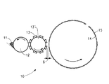
図1は、本発明によってパターン化フルオロポリマーフィルムを基材上に形成するためのフレキソ印刷校正装置の使用を示す。図1に示されるように、コーティング設備10において、フルオロポリマー溶液11はアニロックスロール12によって拾い上げられる。アニロックスロールは、均一フルオロポリマー溶液フィルムをリザーバから引き出す精密彫刻気泡表面ロールを含む印刷工業の標準化用具である。フルオロポリマー溶液の厚さは、選択された特定のアニロックスセル幾何学形状によって制御される。このフルオロポリマー溶液フィルムの一部は、ドラム13’上に配置された、サイレル(登録商標)フレキソ印刷プレートなどのプレートインプレッション6を有する凸版印刷プレート13に転写される。回転ドラム14上に配置された、トリアセチルセルロース(TAC)フィルムなどの基材15がフルオロポリマー溶液11を凸版印刷プレート13から拾い上げ、レリーフ画像を基材上に形成する。乾燥されたレリーフ画像は、基材上の反射防止フィルムとして役立つ。これを所望の数のパスで繰り返してフルオロポリマーフィルムの所望の厚さを製造することができる。
FIG. 1 illustrates the use of a flexographic proofing apparatus to form a patterned fluoropolymer film on a substrate according to the present invention. As shown in FIG. 1, in a
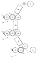
図2は、連続方法で多数のフィルムを形成するために3つの不連続な印刷設備を利用してロール素材を使用する連続方法を示す。図2に示されるように、コートされる基材は、ロール17から巻出され、図1に示されたコーティング設備10および乾燥設備16を通り過ぎる。コートおよび乾燥された基材上にコーティング設備10から、コーティング設備10a〜10nおよび乾燥設備16aおよび16nに示されるように付加的なコーティングおよび乾燥を行うことができる。形成されるフィルムの所望の厚さに応じて任意の数のコーティング設備が10aと10nとの間に存在してもよく、または基材の表面上に多層を含む反射防止フィルムを形成するために異なったコーティング組成物が各コーティング設備において適用されてもよい。コーティング設備10aおよび10nそれぞれにおいて、組成物11aおよび11nがアニロックスロール12aおよび12nによって拾い上げられ、ドラム13a’および13n’上に配置された、凸版印刷プレート13aおよび13nに転写される。次に、コーティング設備10nからのコートおよび乾燥された基材が、示されるようにアイドラーロール19を通り過ぎてロール18上に巻き取られる。3つの設備においてのコーティング組成物は、同じかまたは異なっていてもよい(例えば、接着促進剤、フルオロポリマー溶液、ハードコート)。
FIG. 2 illustrates a continuous process that uses a roll stock utilizing three discontinuous printing facilities to form multiple films in a continuous process. As shown in FIG. 2, the substrate to be coated is unwound from the
前記方法の直接製品は、その上にパターン化フルオロポリマーフィルムが形成された一定の長さの基材である。前記製品は、取扱および/または後続の加工作業を容易にするロールの形で保管されてもよい。 The direct product of the method is a length of substrate on which a patterned fluoropolymer film is formed. The product may be stored in the form of a roll that facilitates handling and / or subsequent processing operations.
本発明によって、形成されるフルオロポリマーフィルム画像は、互いに離隔された画像の連続からなってもよい。この場合、印刷を連続的に実施して画像の連続を製造する。画像は、印刷の方向に離隔される。 According to the present invention, the fluoropolymer film image formed may consist of a series of images spaced apart from each other. In this case, printing is performed continuously to produce a series of images. Images are spaced apart in the direction of printing.
(実施例1)
200lpiのアニロックスロールと画像化および硬化されて5cm×5cmの印刷表面を生じるサイレル(登録商標)PLB45(米国、デラウェア州、ウィルミントンの本願特許出願人)印刷プレートとを備えたGMS・プルーフィング・プレス(GMS Proofing Press)(英国、マンチェスターのグローバル・メディア・ソリューション社(Global Media Solutions Ltd.,Manchester,England))を用いて、テフロン(登録商標)AF1601(米国、デラウェア州、ウィルミントンの本願特許出願人、テトラフルオロエチレンとペルフルオロ−2,2−ジメチル−1,3−ジオキソールとの非晶質コポリマー)の多層をフルオリナート(登録商標)FC−40フルオロ溶剤(米国、ミネソタ州、セントポールの3M)中の6.0、3.0および1.5重量%のテフロン(登録商標)AF1601の溶液から高透明度200Dマイラー(Mylar)(登録商標)(米国、デラウェア州、ウィルミントンの本願特許出願人)上にプルーファー(proofer)のドラム回転について約240フィート/分で堆積した。湿潤層を印刷プレートの鮮明な正確なパターンで転写し、均一に乾燥した。ダブルインプレッションプリント/ドライ、プリント/ドライ方法のための測定されたテフロン(登録商標)AF1601フルオロポリマーフィルムの厚さは、上の6.0、3.0および1.5重量%のテフロン(登録商標)AF1601溶液それぞれについて1000nm、500nmおよび200nmであった。厚さはフィルメトリクス(Filmetrics)F−20反射率スペクトル分析器(米国、カリフォルニア州、サンディエゴのフィルメトリクス社(Filmetrics Inc.,San Diego,CA,USA))によって測定された。製造されたフィルムは視覚的に均一かつ連続的であった。
Example 1
GMS proofing with 200 lpi anilox roll and Cyrell® PLB45 (Patent Applicant of Wilmington, Delaware, USA) printing plate that is imaged and cured to produce a 5 cm x 5 cm printing surface Teflon AF1601 (Wilmington, Delaware, USA) using Press (GMS Proofing Press) (Global Media Solutions Ltd., Manchester, England) Applicant, an amorphous copolymer of tetrafluoroethylene and perfluoro-2,2-dimethyl-1,3-dioxole) with a fluorinate® FC-40 fluoro solvent From a solution of 6.0, 3.0 and 1.5 wt% Teflon AF1601 in (3M St. Paul, MN, USA) from a highly transparent 200D Mylar® (USA, Deposited at about 240 ft / min for proofer drum rotation on Wilmington, Delaware. The wet layer was transferred in a clear and accurate pattern on the printing plate and dried uniformly. The measured Teflon® AF1601 fluoropolymer film thickness for double impression printing / drying and printing / drying methods is 6.0, 3.0 and 1.5 wt% Teflon® ) 1000 nm, 500 nm and 200 nm for each AF1601 solution. Thickness was measured with a Filmmetrics F-20 reflectance spectrum analyzer (Firmetics Inc., San Diego, Calif., USA). The film produced was visually uniform and continuous.
(実施例2)
より微細な440lpiのアニロックスロールと同じサイレル(登録商標)PLB45プレートとを有する実施例1のGMSプレスおよび様々なフルオロ溶剤(FC−40、ペルフルオロオクチルエチレン(PFOE)、ペルフルオロオクタン(PFO))中の3.0〜4.0重量%のテフロン(登録商標)AF1601溶液を用いて、200Dマイラー上に70nm〜120nmの厚さの範囲のシングルインプレッション厚さのフルオロポリマーフィルムを形成した。厚さはフィルメトリクス(Filmetrics)F−20反射率スペクトル分析器によって測定された。製造されたフィルムは視覚的に均一かつ連続的であった。
(Example 2)
Example 1 GMS press with finer 440 lpi anilox roll and the same Cyrel® PLB45 plate and in various fluoro solvents (FC-40, perfluorooctylethylene (PFOE), perfluorooctane (PFO)) A single impression thickness fluoropolymer film ranging from 70 nm to 120 nm thick was formed on 200D Mylar using 3.0-4.0 wt% Teflon AF1601 solution. Thickness was measured by a Filmmetrics F-20 reflectance spectrum analyzer. The film produced was visually uniform and continuous.
(実施例3)
マーク・アンディ(Mark−Andy)印刷プレス(12インチの幅、米国、ミズーリ州、セントルイスのマーク−アンディ社(Mark−Andy,Inc.,St.Louis,MO, USA))は、440lpiのアニロックスおよび3.5インチ×7インチの画像化および硬化されたサイレル(登録商標)PLB45プレートを備えた。PFO/PFOEの85/15重量比の溶剤混合物中1.25重量%のテフロン(登録商標)SF50(米国、デラウェア州、ウィルミントンの本願特許出願人、テトラフルオロエチレンとヘキサフルオロプロピレンとの非晶質等モルコポリマー)溶液を500Aマイラー(米国、デラウェア州、ウィルミントンの本願特許出願人)基材上に28、120および150フィート/分のラインスピードで連続的に堆積し、SEM断面から推定した時におよそ20nm〜30nmの厚さの極薄SF50フルオロポリマーフィルムを製造した。
(Example 3)
Mark-Andy printing press (12 inches wide, Mark-Andy, Inc., St. Louis, MO, USA), St. Louis, Missouri, USA, 440 lpi Anilox and A 3.5 inch × 7 inch imaging and cured Cyrel® PLB45 plate was provided. 1.25 wt.% Teflon SF50 in a 85/15 wt. Ratio solvent mixture of PFO / PFOE (patent applicant of Wilmington, Delaware, USA, amorphous of tetrafluoroethylene and hexafluoropropylene) Quality equimolar copolymer) solution was continuously deposited on a 500A mylar (patent applicant of Wilmington, Delaware, USA) substrate at line speeds of 28, 120 and 150 ft / min, estimated from SEM cross-section Sometimes ultrathin SF50 fluoropolymer films with a thickness of approximately 20 nm to 30 nm were produced.
Claims (17)
(b)前記溶剤を前記パターン化フルオロポリマー溶液層から乾燥させ、それによってパターン化フルオロポリマーフィルムを前記基材上に形成する工程とを含むことを特徴とする、パターン化フルオロポリマーフィルムを基材上に形成するための方法。 (A) a step of printing a relief polymer on a substrate with a patterned relief relief printing plate, thereby forming a patterned fluoropolymer solution layer on the substrate, wherein the fluoropolymer solution is fluoro A process comprising a polymer and a solvent;
(B) drying the solvent from the patterned fluoropolymer solution layer, thereby forming a patterned fluoropolymer film on the substrate, wherein the patterned fluoropolymer film is a substrate. Method for forming on.
(b)溶剤を前記湿潤画像から乾燥させてフルオロポリマーフィルムを形成し、前記フルオロポリマーフィルムの厚さが、入射光の反射防止性を提供するように入射光の波長の約1/4であるように制御され、かつ均一である、工程とを含むことを特徴とする、反射防止フィルムを基材上に形成するための方法。 (A) flexographically printing an amorphous fluoropolymer solution onto an optically transparent substrate to form a wet image on the substrate;
(B) drying the solvent from the wet image to form a fluoropolymer film, the thickness of the fluoropolymer film being about ¼ of the wavelength of the incident light so as to provide antireflective properties of the incident light The method for forming an antireflection film on a substrate, characterized in that the method comprises the steps of being controlled and uniform.
(b)非晶質フルオロポリマーの溶液を前記接着促進剤層上にフレキソ印刷して湿潤画像を前記接着促進剤層上に形成する工程と、
(c)溶剤を前記湿潤画像から乾燥させて非晶質フルオロポリマーフィルムを形成する工程と、
(d)ハードコート層を前記非晶質フルオロポリマーフィルム上にフレキソ印刷し、得られた反射防止フィルムの厚さが、入射光の反射防止性を提供するように入射光の波長の約1/4であるように制御され、かつ均一である、工程とを含むことを特徴とする、反射防止フィルムを基材上に形成するための方法。 (A) flexographically printing an adhesion promoter layer on an optically transparent substrate;
(B) flexographically printing a solution of amorphous fluoropolymer on the adhesion promoter layer to form a wet image on the adhesion promoter layer;
(C) drying the solvent from the wet image to form an amorphous fluoropolymer film;
(D) flexographically printing the hardcoat layer on the amorphous fluoropolymer film and the resulting antireflective film thickness is about 1 / wavelength of the incident light so as to provide antireflective properties of the incident light. 4. A method for forming an antireflective film on a substrate, comprising the steps of being controlled to be uniform and uniform.
Applications Claiming Priority (2)
| Application Number | Priority Date | Filing Date | Title |
|---|---|---|---|
| US63782004P | 2004-12-21 | 2004-12-21 | |
| PCT/US2005/046261 WO2006069102A1 (en) | 2004-12-21 | 2005-12-19 | Process for forming a patterned fluoropolymer film on a substrate |
Publications (2)
| Publication Number | Publication Date |
|---|---|
| JP2008524403A true JP2008524403A (en) | 2008-07-10 |
| JP2008524403A5 JP2008524403A5 (en) | 2009-01-29 |
Family
ID=36084308
Family Applications (1)
| Application Number | Title | Priority Date | Filing Date |
|---|---|---|---|
| JP2007547035A Withdrawn JP2008524403A (en) | 2004-12-21 | 2005-12-19 | Method for forming a patterned fluoropolymer film on a substrate |
Country Status (7)
| Country | Link |
|---|---|
| US (2) | US20060134323A1 (en) |
| EP (1) | EP1831730A1 (en) |
| JP (1) | JP2008524403A (en) |
| KR (1) | KR20070092291A (en) |
| CN (1) | CN100541234C (en) |
| TW (1) | TW200628524A (en) |
| WO (1) | WO2006069102A1 (en) |
Cited By (1)
| Publication number | Priority date | Publication date | Assignee | Title |
|---|---|---|---|---|
| JP2018062158A (en) * | 2016-10-14 | 2018-04-19 | 日本電子精機株式会社 | Printing plate calibration device, calibration method, and printing plate delivery method |
Families Citing this family (49)
| Publication number | Priority date | Publication date | Assignee | Title |
|---|---|---|---|---|
| US20080083484A1 (en) * | 2006-09-28 | 2008-04-10 | Graciela Beatriz Blanchet | Method to form a pattern of functional material on a substrate |
| US20100112299A1 (en) * | 2007-04-19 | 2010-05-06 | Norimitsu Matsushita | Process for producing photosensitive resin printing plate having concave-convex shape and relief printing plate, and plate surface treatment solution for use in the process |
| TWI366677B (en) * | 2007-12-28 | 2012-06-21 | Ind Tech Res Inst | Electrowetting display devices and fabrication methods thereof |
| US7959598B2 (en) | 2008-08-20 | 2011-06-14 | Asante Solutions, Inc. | Infusion pump systems and methods |
| US20140036223A1 (en) * | 2011-02-03 | 2014-02-06 | Essilor International (Compagnie Generale D'optique) | Self-healing transparent coatings containing mineral conductive colloids |
| WO2013082488A2 (en) | 2011-11-30 | 2013-06-06 | Corning Incorporated | Optical coating method, apparatus and product |
| US9957609B2 (en) | 2011-11-30 | 2018-05-01 | Corning Incorporated | Process for making of glass articles with optical and easy-to-clean coatings |
| US10077207B2 (en) | 2011-11-30 | 2018-09-18 | Corning Incorporated | Optical coating method, apparatus and product |
| TWI597523B (en) * | 2012-02-28 | 2017-09-01 | Asahi Glass Co Ltd | Electrowetting device, display device, lens (2) |
| WO2013149186A1 (en) | 2012-03-30 | 2013-10-03 | Insulet Corporation | Fluid delivery device with transcutaneous access tool, insertion mechansim and blood glucose monitoring for use therewith |
| CN102926197B (en) * | 2012-11-15 | 2014-05-07 | 杭州水处理技术研究开发中心有限公司 | Manufacturing method of support cloth for preparation of ion exchange membrane |
| US9561324B2 (en) | 2013-07-19 | 2017-02-07 | Bigfoot Biomedical, Inc. | Infusion pump system and method |
| GB2523989B (en) | 2014-01-30 | 2020-07-29 | Insulet Netherlands B V | Therapeutic product delivery system and method of pairing |
| KR101636450B1 (en) * | 2015-01-23 | 2016-07-06 | 인하대학교 산학협력단 | Fabrication method for conductive adhesive film and the conductive adhesive film thereby |
| CN104678547A (en) * | 2015-02-02 | 2015-06-03 | 华南师范大学 | Electrowetting substrate, manufacturing method thereof and electrowetting display device |
| AU2016219961B2 (en) | 2015-02-18 | 2020-07-02 | Insulet Corporation | Fluid delivery and infusion devices, and methods of use thereof |
| WO2017091584A1 (en) | 2015-11-25 | 2017-06-01 | Insulet Corporation | Wearable medication delivery device |
| CN106945384A (en) * | 2016-01-06 | 2017-07-14 | 浙江德钜铝业有限公司 | A kind of Sai Yin get combination of rigidity and flexibility color coating metallic plate and its finishing system and coating process |
| WO2017123525A1 (en) | 2016-01-13 | 2017-07-20 | Bigfoot Biomedical, Inc. | User interface for diabetes management system |
| US10780223B2 (en) | 2016-01-14 | 2020-09-22 | Bigfoot Biomedical, Inc. | Adjusting insulin delivery rates |
| US10610643B2 (en) | 2016-01-14 | 2020-04-07 | Bigfoot Biomedical, Inc. | Occlusion resolution in medication delivery devices, systems, and methods |
| US10363342B2 (en) * | 2016-02-04 | 2019-07-30 | Insulet Corporation | Anti-inflammatory cannula |
| WO2018058041A1 (en) | 2016-09-23 | 2018-03-29 | Insulet Corporation | Fluid delivery device with sensor |
| AU2017376111B2 (en) | 2016-12-12 | 2023-02-02 | Bigfoot Biomedical, Inc. | Alarms and alerts for medication delivery devices and related systems and methods |
| US11027063B2 (en) | 2017-01-13 | 2021-06-08 | Bigfoot Biomedical, Inc. | Insulin delivery methods, systems and devices |
| WO2018132754A1 (en) | 2017-01-13 | 2018-07-19 | Mazlish Bryan | System and method for adjusting insulin delivery |
| WO2018156548A1 (en) | 2017-02-22 | 2018-08-30 | Insulet Corporation | Needle insertion mechanisms for drug containers |
| WO2019067367A1 (en) | 2017-09-26 | 2019-04-04 | Insulet Corporation | Needle mechanism module for drug delivery device |
| US11147931B2 (en) | 2017-11-17 | 2021-10-19 | Insulet Corporation | Drug delivery device with air and backflow elimination |
| USD928199S1 (en) | 2018-04-02 | 2021-08-17 | Bigfoot Biomedical, Inc. | Medication delivery device with icons |
| CA3099113A1 (en) | 2018-05-04 | 2019-11-07 | Insulet Corporation | Safety constraints for a control algorithm-based drug delivery system |
| CN112789070A (en) | 2018-09-28 | 2021-05-11 | 英赛罗公司 | Mode of activity of the artificial pancreas System |
| WO2020077223A1 (en) | 2018-10-11 | 2020-04-16 | Insulet Corporation | Event detection for drug delivery system |
| USD920343S1 (en) | 2019-01-09 | 2021-05-25 | Bigfoot Biomedical, Inc. | Display screen or portion thereof with graphical user interface associated with insulin delivery |
| US11801344B2 (en) | 2019-09-13 | 2023-10-31 | Insulet Corporation | Blood glucose rate of change modulation of meal and correction insulin bolus quantity |
| US11935637B2 (en) | 2019-09-27 | 2024-03-19 | Insulet Corporation | Onboarding and total daily insulin adaptivity |
| US11957875B2 (en) | 2019-12-06 | 2024-04-16 | Insulet Corporation | Techniques and devices providing adaptivity and personalization in diabetes treatment |
| US11833329B2 (en) | 2019-12-20 | 2023-12-05 | Insulet Corporation | Techniques for improved automatic drug delivery performance using delivery tendencies from past delivery history and use patterns |
| JP7512395B2 (en) | 2020-01-06 | 2024-07-08 | インスレット コーポレイション | Predicting dietary and/or exercise behavior based on persistence residuals |
| US11551802B2 (en) | 2020-02-11 | 2023-01-10 | Insulet Corporation | Early meal detection and calorie intake detection |
| US11547800B2 (en) | 2020-02-12 | 2023-01-10 | Insulet Corporation | User parameter dependent cost function for personalized reduction of hypoglycemia and/or hyperglycemia in a closed loop artificial pancreas system |
| US11986630B2 (en) | 2020-02-12 | 2024-05-21 | Insulet Corporation | Dual hormone delivery system for reducing impending hypoglycemia and/or hyperglycemia risk |
| US11324889B2 (en) | 2020-02-14 | 2022-05-10 | Insulet Corporation | Compensation for missing readings from a glucose monitor in an automated insulin delivery system |
| US11607493B2 (en) | 2020-04-06 | 2023-03-21 | Insulet Corporation | Initial total daily insulin setting for user onboarding |
| US11684716B2 (en) | 2020-07-31 | 2023-06-27 | Insulet Corporation | Techniques to reduce risk of occlusions in drug delivery systems |
| US11904140B2 (en) | 2021-03-10 | 2024-02-20 | Insulet Corporation | Adaptable asymmetric medicament cost component in a control system for medicament delivery |
| US11738144B2 (en) | 2021-09-27 | 2023-08-29 | Insulet Corporation | Techniques enabling adaptation of parameters in aid systems by user input |
| US11439754B1 (en) | 2021-12-01 | 2022-09-13 | Insulet Corporation | Optimizing embedded formulations for drug delivery |
| US12097355B2 (en) | 2023-01-06 | 2024-09-24 | Insulet Corporation | Automatically or manually initiated meal bolus delivery with subsequent automatic safety constraint relaxation |
Family Cites Families (14)
| Publication number | Priority date | Publication date | Assignee | Title |
|---|---|---|---|---|
| US4323636A (en) | 1971-04-01 | 1982-04-06 | E. I. Du Pont De Nemours And Company | Photosensitive block copolymer composition and elements |
| CA1099435A (en) * | 1971-04-01 | 1981-04-14 | Gwendyline Y. Y. T. Chen | Photosensitive block copolymer composition and elements |
| US4975505A (en) | 1981-08-20 | 1990-12-04 | E. I. Du Pont De Nemours And Company | Amorphous copolymers of perfluoro-2,2-dimethyl-1,3-dioxole |
| US5104929A (en) | 1988-04-11 | 1992-04-14 | Minnesota Mining And Manufacturing Company | Abrasion resistant coatings comprising silicon dioxide dispersions |
| US5061024C1 (en) * | 1989-09-06 | 2002-02-26 | Dupont Photomasks Inc | Amorphous fluoropolymer pellicle films |
| US5139879A (en) | 1991-09-20 | 1992-08-18 | Allied-Signal Inc. | Fluoropolymer blend anti-reflection coatings and coated articles |
| JPH07276789A (en) * | 1994-04-05 | 1995-10-24 | Fuji Photo Film Co Ltd | Recording sheet |
| US6040356A (en) * | 1996-08-28 | 2000-03-21 | Dai Nippon Printing Co., Ltd. | Durable gravure ink and uses of the same |
| US6245428B1 (en) | 1998-06-10 | 2001-06-12 | Cpfilms Inc. | Low reflective films |
| US6778240B2 (en) | 2000-03-28 | 2004-08-17 | Fuji Photo Film Co., Ltd. | Anti-glare and anti-reflection film, polarizing plate, and image display device |
| US6505942B2 (en) | 2000-04-07 | 2003-01-14 | Tomoegawa Paper Co., Ltd. | Anti-reflection material, polarization film, and production methods therefor |
| JP4485201B2 (en) * | 2001-10-24 | 2010-06-16 | イー・アイ・デュポン・ドウ・ヌムール・アンド・カンパニー | Continuous production of catalyst-coated membranes |
| JP4069369B2 (en) * | 2002-09-25 | 2008-04-02 | 信越化学工業株式会社 | Antireflection film and method of manufacturing antireflection film |
| US20050228152A1 (en) * | 2004-04-08 | 2005-10-13 | Starry Adam B | Anti-reflective coating |
-
2005
- 2005-12-19 KR KR1020077016628A patent/KR20070092291A/en not_active Application Discontinuation
- 2005-12-19 JP JP2007547035A patent/JP2008524403A/en not_active Withdrawn
- 2005-12-19 WO PCT/US2005/046261 patent/WO2006069102A1/en active Application Filing
- 2005-12-19 EP EP05854901A patent/EP1831730A1/en not_active Withdrawn
- 2005-12-19 CN CNB2005800441520A patent/CN100541234C/en not_active Expired - Fee Related
- 2005-12-20 US US11/312,069 patent/US20060134323A1/en not_active Abandoned
- 2005-12-21 TW TW094145436A patent/TW200628524A/en unknown
-
2008
- 2008-01-25 US US12/019,853 patent/US20080250955A1/en not_active Abandoned
Cited By (1)
| Publication number | Priority date | Publication date | Assignee | Title |
|---|---|---|---|---|
| JP2018062158A (en) * | 2016-10-14 | 2018-04-19 | 日本電子精機株式会社 | Printing plate calibration device, calibration method, and printing plate delivery method |
Also Published As
| Publication number | Publication date |
|---|---|
| US20060134323A1 (en) | 2006-06-22 |
| KR20070092291A (en) | 2007-09-12 |
| US20080250955A1 (en) | 2008-10-16 |
| CN100541234C (en) | 2009-09-16 |
| WO2006069102A1 (en) | 2006-06-29 |
| EP1831730A1 (en) | 2007-09-12 |
| TW200628524A (en) | 2006-08-16 |
| CN101084456A (en) | 2007-12-05 |
Similar Documents
| Publication | Publication Date | Title |
|---|---|---|
| JP2008524403A (en) | Method for forming a patterned fluoropolymer film on a substrate | |
| JP2008524403A5 (en) | ||
| TWI620949B (en) | Anti-reflective hard coat and anti-reflective article | |
| TWI586534B (en) | Resin film, composition for resin film, and method of manufacturing the resin film | |
| KR101356903B1 (en) | Optical film | |
| TWI357916B (en) | Hard-coated antiglare film, polarizing plate, and | |
| CN104540900B (en) | Antifouling hard and antifouling hard precursor | |
| CN101268389B (en) | Antistatic anti-glare film | |
| US8422133B2 (en) | Optical layered body, polarizer, and image display device | |
| TWI534002B (en) | Optical laminate and method for manufacturing optical laminate | |
| WO2014109407A1 (en) | Hard coat film, curable resin composition for hard coat layers, and method for producing hard coat film | |
| CN104379675A (en) | Nanostructured materials and methods of making the same | |
| JP2001264520A (en) | Reflection preventing film, polarizing element, display device and method for manufacturing reflection preventing film | |
| JP2009114248A (en) | Curable composition and resin plate having cured coating film | |
| US20070139780A1 (en) | Process for producing coating film, antireflection film and process for producing the same, sheet polarizer using the film, and image display device using these | |
| CN109196390A (en) | Optical laminate | |
| JP2009017305A (en) | Method of manufacturing dust-proof light transmissive member, its application and imaging apparatus provided with the member | |
| JP2006206712A (en) | Coating composition, optical film, antireflection film, polarizing plate and display device using those | |
| WO2020114225A1 (en) | Combined coating of projection screen and preparation method for projection screen | |
| WO2017115694A1 (en) | Optical member and method for producing optical member | |
| JP5150055B2 (en) | Anti-reflective material | |
| JP2006233191A (en) | Coating composition, optical film, antireflection film, polarizing plate and image display device using them | |
| KR100551135B1 (en) | Producing method of the reflection preventive transparent sheet with a excellent antipollution | |
| US10094952B2 (en) | Anti-reflection film, method of producing the film and display device | |
| WO2007046275A1 (en) | Glareless film, polarizing plate and display |
Legal Events
| Date | Code | Title | Description |
|---|---|---|---|
| A521 | Request for written amendment filed |
Free format text: JAPANESE INTERMEDIATE CODE: A523 Effective date: 20081204 |
|
| A621 | Written request for application examination |
Free format text: JAPANESE INTERMEDIATE CODE: A621 Effective date: 20081204 |
|
| A761 | Written withdrawal of application |
Free format text: JAPANESE INTERMEDIATE CODE: A761 Effective date: 20091210 |