JP2008521453A - End scope - Google Patents
End scope Download PDFInfo
- Publication number
- JP2008521453A JP2008521453A JP2007541585A JP2007541585A JP2008521453A JP 2008521453 A JP2008521453 A JP 2008521453A JP 2007541585 A JP2007541585 A JP 2007541585A JP 2007541585 A JP2007541585 A JP 2007541585A JP 2008521453 A JP2008521453 A JP 2008521453A
- Authority
- JP
- Japan
- Prior art keywords
- tissue
- endoscope
- light
- detector
- image
- Prior art date
- Legal status (The legal status is an assumption and is not a legal conclusion. Google has not performed a legal analysis and makes no representation as to the accuracy of the status listed.)
- Pending
Links
- 238000002073 fluorescence micrograph Methods 0.000 claims abstract description 17
- 239000000835 fiber Substances 0.000 claims description 35
- 239000002872 contrast media Substances 0.000 claims description 22
- 238000000034 method Methods 0.000 claims description 20
- NJDNXYGOVLYJHP-UHFFFAOYSA-L disodium;2-(3-oxido-6-oxoxanthen-9-yl)benzoate Chemical group [Na+].[Na+].[O-]C(=O)C1=CC=CC=C1C1=C2C=CC(=O)C=C2OC2=CC([O-])=CC=C21 NJDNXYGOVLYJHP-UHFFFAOYSA-L 0.000 claims description 10
- 238000001514 detection method Methods 0.000 claims description 9
- 238000001000 micrograph Methods 0.000 claims description 7
- 238000005286 illumination Methods 0.000 claims description 6
- 230000005284 excitation Effects 0.000 claims description 4
- 230000001678 irradiating effect Effects 0.000 claims description 4
- 230000003287 optical effect Effects 0.000 claims description 3
- 238000001429 visible spectrum Methods 0.000 claims description 2
- 229940039231 contrast media Drugs 0.000 claims 2
- KKAJSJJFBSOMGS-UHFFFAOYSA-N 3,6-diamino-10-methylacridinium chloride Chemical compound [Cl-].C1=C(N)C=C2[N+](C)=C(C=C(N)C=C3)C3=CC2=C1 KKAJSJJFBSOMGS-UHFFFAOYSA-N 0.000 claims 1
- 229940023020 acriflavine Drugs 0.000 claims 1
- 230000008520 organization Effects 0.000 claims 1
- 210000004027 cell Anatomy 0.000 description 9
- 238000001574 biopsy Methods 0.000 description 6
- 238000010586 diagram Methods 0.000 description 5
- 230000003902 lesion Effects 0.000 description 5
- 210000001072 colon Anatomy 0.000 description 4
- 238000003780 insertion Methods 0.000 description 4
- 230000037431 insertion Effects 0.000 description 4
- 238000011835 investigation Methods 0.000 description 4
- 238000012545 processing Methods 0.000 description 4
- 238000010253 intravenous injection Methods 0.000 description 3
- 206010058314 Dysplasia Diseases 0.000 description 2
- 238000009825 accumulation Methods 0.000 description 2
- 230000035508 accumulation Effects 0.000 description 2
- 210000003850 cellular structure Anatomy 0.000 description 2
- 238000009826 distribution Methods 0.000 description 2
- 239000000463 material Substances 0.000 description 2
- 238000012986 modification Methods 0.000 description 2
- 230000004048 modification Effects 0.000 description 2
- 239000013307 optical fiber Substances 0.000 description 2
- 238000002271 resection Methods 0.000 description 2
- 206010028980 Neoplasm Diseases 0.000 description 1
- PEJLNXHANOHNSU-UHFFFAOYSA-N acridine-3,6-diamine;10-methylacridin-10-ium-3,6-diamine;chloride Chemical compound [Cl-].C1=CC(N)=CC2=NC3=CC(N)=CC=C3C=C21.C1=C(N)C=C2[N+](C)=C(C=C(N)C=C3)C3=CC2=C1 PEJLNXHANOHNSU-UHFFFAOYSA-N 0.000 description 1
- 230000001413 cellular effect Effects 0.000 description 1
- 239000003795 chemical substances by application Substances 0.000 description 1
- 238000003745 diagnosis Methods 0.000 description 1
- 201000010099 disease Diseases 0.000 description 1
- 208000037265 diseases, disorders, signs and symptoms Diseases 0.000 description 1
- 230000000694 effects Effects 0.000 description 1
- 238000001914 filtration Methods 0.000 description 1
- 238000000799 fluorescence microscopy Methods 0.000 description 1
- 210000001035 gastrointestinal tract Anatomy 0.000 description 1
- 238000003384 imaging method Methods 0.000 description 1
- 238000001727 in vivo Methods 0.000 description 1
- 238000001802 infusion Methods 0.000 description 1
- 238000002347 injection Methods 0.000 description 1
- 239000007924 injection Substances 0.000 description 1
- 238000005192 partition Methods 0.000 description 1
- 230000001575 pathological effect Effects 0.000 description 1
- 238000002310 reflectometry Methods 0.000 description 1
- 238000012552 review Methods 0.000 description 1
- 230000035945 sensitivity Effects 0.000 description 1
- 239000000243 solution Substances 0.000 description 1
Images


Classifications
-
- A—HUMAN NECESSITIES
- A61—MEDICAL OR VETERINARY SCIENCE; HYGIENE
- A61B—DIAGNOSIS; SURGERY; IDENTIFICATION
- A61B1/00—Instruments for performing medical examinations of the interior of cavities or tubes of the body by visual or photographical inspection, e.g. endoscopes; Illuminating arrangements therefor
- A61B1/04—Instruments for performing medical examinations of the interior of cavities or tubes of the body by visual or photographical inspection, e.g. endoscopes; Illuminating arrangements therefor combined with photographic or television appliances
- A61B1/05—Instruments for performing medical examinations of the interior of cavities or tubes of the body by visual or photographical inspection, e.g. endoscopes; Illuminating arrangements therefor combined with photographic or television appliances characterised by the image sensor, e.g. camera, being in the distal end portion
-
- A—HUMAN NECESSITIES
- A61—MEDICAL OR VETERINARY SCIENCE; HYGIENE
- A61B—DIAGNOSIS; SURGERY; IDENTIFICATION
- A61B1/00—Instruments for performing medical examinations of the interior of cavities or tubes of the body by visual or photographical inspection, e.g. endoscopes; Illuminating arrangements therefor
- A61B1/04—Instruments for performing medical examinations of the interior of cavities or tubes of the body by visual or photographical inspection, e.g. endoscopes; Illuminating arrangements therefor combined with photographic or television appliances
- A61B1/043—Instruments for performing medical examinations of the interior of cavities or tubes of the body by visual or photographical inspection, e.g. endoscopes; Illuminating arrangements therefor combined with photographic or television appliances for fluorescence imaging
-
- A—HUMAN NECESSITIES
- A61—MEDICAL OR VETERINARY SCIENCE; HYGIENE
- A61B—DIAGNOSIS; SURGERY; IDENTIFICATION
- A61B1/00—Instruments for performing medical examinations of the interior of cavities or tubes of the body by visual or photographical inspection, e.g. endoscopes; Illuminating arrangements therefor
- A61B1/06—Instruments for performing medical examinations of the interior of cavities or tubes of the body by visual or photographical inspection, e.g. endoscopes; Illuminating arrangements therefor with illuminating arrangements
- A61B1/0638—Instruments for performing medical examinations of the interior of cavities or tubes of the body by visual or photographical inspection, e.g. endoscopes; Illuminating arrangements therefor with illuminating arrangements providing two or more wavelengths
-
- A—HUMAN NECESSITIES
- A61—MEDICAL OR VETERINARY SCIENCE; HYGIENE
- A61B—DIAGNOSIS; SURGERY; IDENTIFICATION
- A61B5/00—Measuring for diagnostic purposes; Identification of persons
- A61B5/0059—Measuring for diagnostic purposes; Identification of persons using light, e.g. diagnosis by transillumination, diascopy, fluorescence
- A61B5/0062—Arrangements for scanning
- A61B5/0068—Confocal scanning
-
- A—HUMAN NECESSITIES
- A61—MEDICAL OR VETERINARY SCIENCE; HYGIENE
- A61B—DIAGNOSIS; SURGERY; IDENTIFICATION
- A61B5/00—Measuring for diagnostic purposes; Identification of persons
- A61B5/0059—Measuring for diagnostic purposes; Identification of persons using light, e.g. diagnosis by transillumination, diascopy, fluorescence
- A61B5/0071—Measuring for diagnostic purposes; Identification of persons using light, e.g. diagnosis by transillumination, diascopy, fluorescence by measuring fluorescence emission
-
- A—HUMAN NECESSITIES
- A61—MEDICAL OR VETERINARY SCIENCE; HYGIENE
- A61B—DIAGNOSIS; SURGERY; IDENTIFICATION
- A61B5/00—Measuring for diagnostic purposes; Identification of persons
- A61B5/0059—Measuring for diagnostic purposes; Identification of persons using light, e.g. diagnosis by transillumination, diascopy, fluorescence
- A61B5/0082—Measuring for diagnostic purposes; Identification of persons using light, e.g. diagnosis by transillumination, diascopy, fluorescence adapted for particular medical purposes
- A61B5/0084—Measuring for diagnostic purposes; Identification of persons using light, e.g. diagnosis by transillumination, diascopy, fluorescence adapted for particular medical purposes for introduction into the body, e.g. by catheters
-
- A—HUMAN NECESSITIES
- A61—MEDICAL OR VETERINARY SCIENCE; HYGIENE
- A61B—DIAGNOSIS; SURGERY; IDENTIFICATION
- A61B1/00—Instruments for performing medical examinations of the interior of cavities or tubes of the body by visual or photographical inspection, e.g. endoscopes; Illuminating arrangements therefor
- A61B1/06—Instruments for performing medical examinations of the interior of cavities or tubes of the body by visual or photographical inspection, e.g. endoscopes; Illuminating arrangements therefor with illuminating arrangements
- A61B1/0646—Instruments for performing medical examinations of the interior of cavities or tubes of the body by visual or photographical inspection, e.g. endoscopes; Illuminating arrangements therefor with illuminating arrangements with illumination filters
Landscapes
- Health & Medical Sciences (AREA)
- Life Sciences & Earth Sciences (AREA)
- Surgery (AREA)
- General Health & Medical Sciences (AREA)
- Medical Informatics (AREA)
- Veterinary Medicine (AREA)
- Pathology (AREA)
- Public Health (AREA)
- Biophysics (AREA)
- Engineering & Computer Science (AREA)
- Biomedical Technology (AREA)
- Heart & Thoracic Surgery (AREA)
- Physics & Mathematics (AREA)
- Molecular Biology (AREA)
- Animal Behavior & Ethology (AREA)
- Nuclear Medicine, Radiotherapy & Molecular Imaging (AREA)
- Radiology & Medical Imaging (AREA)
- Optics & Photonics (AREA)
- Investigating, Analyzing Materials By Fluorescence Or Luminescence (AREA)
- Endoscopes (AREA)
- Investigating Or Analysing Materials By Optical Means (AREA)
- Instruments For Viewing The Inside Of Hollow Bodies (AREA)
Abstract
エンドスコープは、生物組織を光で照射するための第1の光源と、反射した光及び前記組織中に誘起された蛍光によって、前記組織からの肉眼で見える画像及び蛍光画像を検出するための第1の検出器と、前記組織を光で照射するための第2の光源と、前記第2の光源から前記組織への前記光を供給するための、及び、前記組織の蛍光顕微鏡画像を供給するための、共焦点顕微鏡導波管と、前記共焦点顕微鏡導波管からの前記蛍光顕微鏡画像を検出するための第2の検出器と、を備える。 The endoscope has a first light source for illuminating a biological tissue with light, and a first light source for detecting a visible image and a fluorescent image from the tissue by reflected light and fluorescence induced in the tissue. 1 detector, a second light source for illuminating the tissue with light, for supplying the light from the second light source to the tissue, and for supplying a fluorescence microscope image of the tissue And a second detector for detecting the fluorescence microscope image from the confocal microscope waveguide.
Description
本発明は、エンドスコープに関する。 The present invention relates to an end scope.
エンドスコープは、様々な疾患及び病理学的状態に対する消化管の内壁を撮像するために、今日広く使われている。伝統的に、通常の光画像は、カラーで表示されて、従来の白色光源を使用して得られる。この白色光源からの光は、エンドスコープの先端から現れるように、光学ファイバを介して送信される。組織から反射される光は、エンドスコープの先端に位置しているCCDチップといった検出器によって受信され、そして、この光は、画像が処理されてモニタに表示されうるように、画像処理プロセッサに発信される。より最近において、カラーで蛍光の画像が可能となっている。しかしながら、通常のカラーモード又は蛍光の撮像モードで操作されるかいずれにせよ、この種のシステムで調査される組織の領域に対する肉眼で見える変化だけしか、検出できない。 Endoscopes are widely used today to image the inner wall of the gastrointestinal tract for various diseases and pathological conditions. Traditionally, normal light images are displayed in color and are obtained using a conventional white light source. The light from the white light source is transmitted through an optical fiber so as to emerge from the tip of the end scope. Light reflected from the tissue is received by a detector such as a CCD chip located at the tip of the endoscope, and this light is transmitted to the image processor so that the image can be processed and displayed on a monitor. Is done. More recently, color and fluorescent images have become possible. However, whether operated in normal color mode or fluorescence imaging mode, only visible changes to the area of tissue examined with this type of system can be detected.
本発明は、以下のものを備えるエンドスコープを提供する。
例えば患者のといった、生物組織を照射するための第1の光源と、
反射した光及び前記組織中に誘起された蛍光によって、前記組織からの巨視的な(肉眼で見える)画像及び蛍光画像を検出するための第1の検出器と、
前記組織を光で照射するための第2の光源と、
前記第2の光源から前記組織への前記光を供給するための、及び、前記組織の微視的な(顕微鏡で見える)蛍光画像を供給するための、共焦点顕微鏡導波管と、
前記共焦点顕微鏡導波管からの前記蛍光顕微鏡画像を検出するための第2の検出器と、
を備える。
The present invention provides an end scope comprising:
A first light source for illuminating biological tissue, such as a patient;
A first detector for detecting macroscopic (visible) and fluorescent images from the tissue by reflected light and fluorescence induced in the tissue;
A second light source for irradiating the tissue with light;
A confocal microscope waveguide for supplying the light from the second light source to the tissue and for providing a microscopic (microscopically visible) fluorescent image of the tissue;
A second detector for detecting the fluorescence microscope image from the confocal microscope waveguide;
Is provided.
本発明によれば、内視鏡医は、白色光照明下で組織全体の範囲内において肉眼で見える観察可能な領域又は病変を観察することができ、細胞集団及び構造に対する変化によって周囲組織と異なる濃度で蛍光画像を生成される全体の構造物内の領域を観察するために、肉眼で見える蛍光モードへ切り替えることができる。これらの離散的な領域は、後に続く組織病理学によって更に調査するために領域の生検を行うオペレータによって、更に調査されうる。この種の生検法をとることは患者に若干の危険があり、そして、生検に対して適切な正しい領域が選択されたかどうか、又は、集められた組織の小さい領域がより大きな領域を代表しているかは、生検の結果が約数日後に得られるまで、オペレータにはわからない。本発明によれば、対象となる組織の領域を一旦観察すると、オペレータは、前記領域の蛍光顕微鏡画像を検出するための共焦顕微鏡導波管へ切り替えることができる。これにより、微視的な細胞形態及び細胞構造が実際の操作の間に、ほぼリアルタイムにおいて評価されることが可能となり、保証される場合には、更なる操作のための患者の中で予定を変更することを回避するために、同じ操作の間に患部におけるより広範囲な粘膜切除が行われるという決定がなされうる。このように、3つの画像モード、すなわち肉眼で見える(巨視的な)画像、蛍光画像及び顕微鏡の(微視的な)蛍光画像は、オペレータに対して感度の向上を提供して、小さい病変の存在を巨視的に検出し、そして、これらの検出された病変を微視的に観察して、細胞形態及び細胞構造の性質(例えば、通常構造との整合性、又は、形成異常又は初期の腫瘍形成を示しているか)を決定し、これにより、病変を分類するためのオペレータの選択性が向上し、そして、オペレータは、適切な行動(例えば除去)を次々に選択できる。本発明は、従って、患者の診断の精度の向上をも提供する。 According to the present invention, the endoscopist can observe an observable region or lesion that is visible to the naked eye within the entire tissue under white light illumination, and differs from the surrounding tissue by changes to the cell population and structure. It is possible to switch to the fluorescence mode visible to the naked eye in order to observe the region within the entire structure where the fluorescence image is generated at the density. These discrete areas can be further investigated by an operator performing a biopsy of the area for further investigation by subsequent histopathology. Taking this type of biopsy procedure presents some risk to the patient and whether the correct area appropriate for the biopsy has been selected, or the smaller area of collected tissue is representative of the larger area. The operator does not know if a biopsy result is obtained about a few days later. According to the present invention, once the region of the target tissue is observed, the operator can switch to the confocal microscope waveguide for detecting the fluorescence microscope image of the region. This allows microscopic cell morphology and cell structure to be evaluated in near real-time during the actual operation and, if warranted, can be scheduled in the patient for further operations. To avoid changing, a determination may be made that a more extensive mucosal resection at the affected area will be performed during the same operation. Thus, three image modes, the macroscopic (macroscopic) image, the fluorescence image, and the microscopic (microscopic) fluorescence image provide increased sensitivity to the operator and allow for small lesions. Macroscopically detect the presence and microscopically observe these detected lesions to determine the cellular morphology and cellular structure properties (eg, consistency with normal structure, or dysplasia or early tumor) This will improve the operator's selectivity for classifying the lesion and the operator can in turn select the appropriate action (eg, removal). The present invention therefore also provides improved accuracy of patient diagnosis.
好ましくは、導波管は、第1の光源から組織への光を供給するために提供される。 Preferably, a waveguide is provided for supplying light from the first light source to the tissue.
本発明の一実施の形態において、照射される異なる組織構造が照明光の波長を変更することで第1の検出器への光量を変化させて反射するように、第1の光源は白色光源であって、可視スペクトルによる有効照射を急速に変えるためのフィルタを具備する。 In an embodiment of the present invention, the first light source is a white light source so that different irradiated tissue structures are reflected by changing the amount of light to the first detector by changing the wavelength of the illumination light. A filter is provided for rapidly changing the effective illumination by the visible spectrum.
本実施の形態において、前記検出器は、好ましくはモノクロ検出器である。 In the present embodiment, the detector is preferably a monochrome detector.
他の実施の形態において、前記光源は連続白色光源であってもよく、そして、前記第1の検出器は反射光における異なる波長の様々な光量を検出するためのカラー検出器であってもよい。 In other embodiments, the light source may be a continuous white light source and the first detector may be a color detector for detecting various amounts of light of different wavelengths in the reflected light. .
好ましくは、前記導波管は第1の光源から組織に光を伝えるための単一のファイバ又はファイバーバンドルを備え、そして、前記第1の検出器は前記エンドスコープの自由端にある。 Preferably, the waveguide comprises a single fiber or fiber bundle for transmitting light from a first light source to the tissue, and the first detector is at the free end of the endoscope.
更なる実施の形態において、前記導波管は、前記エンドスコープの自由端へ光を導くための第1の導波管、及び、反射光を受信して、前記第1の検出器に反射光を伝達するための第2の導波管を備える。 In a further embodiment, the waveguide includes a first waveguide for directing light to a free end of the endoscope, and reflected light received by the first detector. Is provided with a second waveguide.
本実施の形態において、前記第1の検出器は、エンドスコープの自由端から離れて位置し、そして、前記第2の導波管によって受け取られる光をフィルタリングするためにエンドスコープの自由端にフィルタが更に設けられてもよく、又は、この更なるフィルタは前記検出器及び前記第2の導波管の間に位置してもよい。 In this embodiment, the first detector is located away from the free end of the endscope and is filtered at the free end of the endscope to filter the light received by the second waveguide. May be further provided, or this further filter may be located between the detector and the second waveguide.
前述の実施の形態のように、前記第1の検出器はモノクロ検出器又はカラー検出器であってもよくて、前記光が前記第1の導波管に提供される前に前記第1の光源からの光をフィルタリングするためのフィルタを具備しうる。 As in the previous embodiment, the first detector may be a monochrome detector or a color detector, and the first detector before the light is provided to the first waveguide. A filter for filtering light from the light source may be provided.
前記第1の導波管及び第2の導波管は、一つのファイバ又はファイバーバンドルであってもよい。 The first waveguide and the second waveguide may be a single fiber or fiber bundle.
好ましくは、前記共焦点顕微鏡導波管は、単一のファイバ又はファイバーバンドルである。 Preferably, the confocal microscope waveguide is a single fiber or fiber bundle.
一実施の形態において、前記共焦点顕微鏡ファイバ又はファイバーバンドルは、蛍光を受信して、前記第2の検出器に蛍光を導くためのファイバ・カプラーを具備する。 In one embodiment, the confocal microscope fiber or fiber bundle comprises a fiber coupler for receiving fluorescence and directing fluorescence to the second detector.
好ましくは、モニタは、肉眼で見えるそして蛍光画像の重なりを含んで単一画像を生成するディスプレイを提供するように設けられる。 Preferably, the monitor is provided to provide a display that produces the single image that is visible to the naked eye and that includes the overlap of the fluorescent images.
好ましくは、前記第2の光源は、共焦点顕微鏡導波管の通過のための所定のモノクロ波長で光を生成するためのものである。 Preferably, the second light source is for generating light at a predetermined monochromatic wavelength for passage through the confocal microscope waveguide.
好ましくは、前記第2の光源は、レーザー光源を備える。 Preferably, the second light source includes a laser light source.
一実施の形態において、前記第1の検出器はプロセッサに接続され、そして、前記検出器は、複数の異なるカラー・チップを具備する。その結果、戻ってくる蛍光の検出を最大化して任意の背景反射光の検出を減少させるために、前記第1の検出器の異なるカラー・チップに対する強度ゲインが調整されうる。 In one embodiment, the first detector is connected to a processor, and the detector comprises a plurality of different color chips. As a result, the intensity gain for the different color chips of the first detector can be adjusted to maximize the detection of the returning fluorescence and reduce the detection of any background reflected light.
好ましくは、前記第2の検出器はプロセッサにも接続している。前記プロセッサが前記画像を処理することができ、肉眼で見える蛍光画像及び蛍光顕微鏡画像をモニタ上に表示できるようにするためである。 Preferably, the second detector is also connected to a processor. This is because the processor can process the image and display a fluorescent image and a fluorescent microscope image visible to the naked eye on a monitor.
好ましくは、前記蛍光は、患者に外生の蛍光造影剤を投与することによって、組織中に誘導される。造影剤は、エンドスコープが挿入されている時に静脈注射(静注)によって患者に投与されるナトリウム・フルオレセイン(NaF)であってもよい。 Preferably, the fluorescence is induced in the tissue by administering an exogenous fluorescent contrast agent to the patient. The contrast agent may be sodium fluorescein (NaF) administered to the patient by intravenous injection (intravenous injection) when the endoscope is inserted.
しかしながら、他の造影剤も、必要に応じて用いられうる。 However, other contrast agents can be used as needed.
本発明は、エンドスコープを用いて患者の組織を検査する方法をも提供する。この方法は、外生の造影剤を患者に適用すること、
患者の組織をエンドスコープで照射すること、
前記エンドスコープによる組織中の光画像を前記エンドスコープで検出すること、
肉眼で見える蛍光性の画像を前記エンドスコープで検出すること、
前記組織中の共焦点顕微鏡蛍光画像を前記エンドスコープで検出すること、
を含む。
The present invention also provides a method for examining patient tissue using an endoscope. This method involves applying an exogenous contrast agent to the patient,
Irradiating the patient's tissue with an endoscope,
Detecting an optical image in the tissue by the endoscope with the endoscope;
Detecting a fluorescent image visible to the naked eye with the endoscope;
Detecting a confocal microscope fluorescence image in the tissue with the endoscope;
including.
好ましくは、前記エンドスコープは、フィルタ及びカラー検出器を具備し、そして、フィルタパラメータ及び前記カラー検出器のゲインは、患者に投与される造影剤に対して、最大の励起及び発光ピークになるように、制御される。 Preferably, the endoscope comprises a filter and a color detector, and the filter parameters and the gain of the color detector are such that the excitation and emission peaks are maximum for the contrast agent administered to the patient. To be controlled.
好ましくは、前記方法は、対象となる領域を確認するために肉眼で見える蛍光画像を検査すること、そして、更にそれらの領域の共焦点蛍光顕微鏡画像を検査することを含む。 Preferably, the method comprises inspecting the fluorescent image visible to the naked eye to identify the area of interest, and further inspecting the confocal fluorescence microscope image of those areas.
一実施の形態において、前記造影剤は、ナトリウム・フルオレセインを備える。しかしながら、他の実施の形態において、前記造影剤は、患者に注入するよりもむしろエンドスコープによって適用されるアクリフラビンであってもよい。 In one embodiment, the contrast agent comprises sodium fluorescein. However, in other embodiments, the contrast agent may be acriflavin applied by the endoscope rather than being injected into the patient.
本発明は、エンドスコープであると言われてもよい。このエンドスコープは、
患者の組織のカラー画像が得られる白色光カラー動作モード、
前記組織の肉眼で見える蛍光画像が得られる肉眼蛍光モード、
前記組織の蛍光顕微鏡画像が得られる共焦点顕微鏡蛍光モード、を備える。
The present invention may be said to be an end scope. This end scope is
White light color operating mode, which gives a color image of the patient's tissue,
Macroscopic fluorescence mode in which a fluorescent image visible to the naked eye of the tissue is obtained;
A confocal microscope fluorescence mode for obtaining a fluorescence microscope image of the tissue.
本発明は、単一のエンドスコープで患者の画像を得る方法にあるとも、言われうる。この方法は、患者に外生の造影剤を投与すること、患者の組織の白色光のカラー画像、肉眼で見える蛍光画像、及び、共焦点蛍光顕微鏡画像を1又は2以上得ること、を含む。 It can also be said that the present invention resides in a method for obtaining an image of a patient with a single endoscope. The method includes administering an exogenous contrast agent to the patient, obtaining one or more of a white light color image, a naked eye fluorescent image, and a confocal fluorescent microscope image of the patient's tissue.
本発明の装置が「エンドスコープ」と称されるが、この用語が装置を内服用又は生体内用途に制限することを意図していないことを理解すべきである。 Although the device of the present invention is referred to as an “endoscope”, it should be understood that this term is not intended to limit the device to internal or in vivo use.
本発明をより明確に確認しうるように、本発明の好適な実施の形態は、図面を参照して例示として記述される。 In order that the present invention may be more clearly ascertained, preferred embodiments of the invention are described by way of example with reference to the drawings.
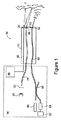
図1を参照すると、患者の組織Tを検査するためのエンドスコープ10が示される。エンドスコープ10は、挿入部12及び光源及び処理部14を有する。
Referring to FIG. 1, an
この処理部14は、白色光を生成するための電球20を具備し、そして、赤から青、緑、白色光に異なる波長を生成してそのサイクルを繰り返すために電球20の前で急速に回転するフィルタホイール22を有しうる。その結果、光の波長を変化させて照射される異なる組織構造が、挿入部12の自由端での検出器30への様々な光量に反映される。フィルタホイール22が典型的に用いられる場合、検出器30はモノクロ検出器(例えばモノクロムCCD)である。他の実施の形態において、フィルタホイール22は省略されてもよく、そして、検出器30は、組織Tから反射された異なる波長の変化する光量を検出するためのマルチチップカラーCCDであってもよい。検出器30は、検出器30からの信号を処理して検出器30で検出された画像を表示するためのプロセッサ及びモニタ40にライン42を介して接続している。
The
光は、単一の光学ファイバ又はファイバーバンドルでありうる導波管44によって、電球20から伝えられる。照明レンズ46は、ファイバ44の端部で提供されうる。
Light is transmitted from the
生物学的に適合した蛍光造影剤(例えばナトリウム・フルオレセイン)は、エンドスコープ10の挿入時に、患者に投与される。この造影剤は、例えば注入によって系統的に、又は、エンドスコープの端から局所的に印加されうる。ナトリウム・フルオレセインの場合、投与は、通常IV注入によってである。
A biologically compatible fluorescent contrast agent (eg, sodium fluorescein) is administered to the patient upon insertion of the
概して、内視鏡医は、白色光照明下で組織Tの領域(例えばコロン)又は病変を観察するが、様々な異なる建造上又は構造上の特性を強調するために外部に印加された蛍光造影剤が組織の様々な細胞構造内で区分しうることを細胞集団及び構造への変化が意味する全体構造の領域を観察するために、巨視的蛍光モードへ切り替えることができる。造影剤の異なる蓄積又は分布を有するこれらの離散的な領域は、白色光カラー画像中でオペレータに見えなくてもよく、そして、一旦検出された場合には、更に調査するようにそれらの存在をオペレータに警告する。 In general, an endoscopist observes a region (eg, a colon) or lesion of tissue T under white light illumination, but is applied externally to enhance various different architectural or structural characteristics. To observe the area of the overall structure where changes to the cell population and structure mean that the agent can partition within the various cellular structures of the tissue, it can be switched to the macroscopic fluorescence mode. These discrete regions with different accumulations or distributions of contrast agent may not be visible to the operator in the white light color image, and once detected, their presence can be further investigated. Alert the operator.
肉眼で見える蛍光モードのエンドスコープを作動するときに、その波長の光を生じるための特定位置にフィルタホイール22を回転させることによって得られうる特定の波長の光によって組織は照射される。例えば、光は、青色光であってもよい。フィルタホイール22が省略されて、そして、カラーCCDチップ型検出器30が用いられる場合、青色フィルタは光源20及びファイバーバンドル44の間に配置されてもよく、又は、あるいは、白色光が通過できるようなクリアーフィルタを有するフィルタホイール及び青いフィルタが用いられてもよい。その結果、フィルタホイールが回転されて肉眼で見える蛍光モードで作動するときに青色フィルタを持ってくる。
When operating a fluorescent mode endoscope visible to the naked eye, the tissue is illuminated by light of a specific wavelength that can be obtained by rotating the
モノクロCCD検出器がフィルタホイール22で用いられる場合、フィルタホイールは特定位置(すなわち青色)において停止しており、そして、第2の離隔したフィルタはエンドスコープの終端で切替えられる。このフィルタは、緑色の蛍光だけが検出されて青色の反射光が検出されないように、緑色のロングパス・フィルタであってもよい。
If a monochrome CCD detector is used with the
エンドスコープ10は、端部で対物レンズ・セット52を有する共焦ファイバ50を更に含む。ファイバ50は、ファイバーバンドルの単一のファイバであってもよくて、光源(例えばレーザー60)から、特定の波長の光を供給する。ファイバ50は、第2の検出器68にファイバ50を介して戻ってくる光を供給するためのシングルモード・ファイバ・カプラー66を有する。そして、検出器68は、モニタ上に画像を表示するためのプロセッサに出力を供給することができる。このプロセッサ及びモニタは、プロセッサ及びモニタ40と同様でもよく、又は、異なるプロセッサ及びモニタであってもよい。
The
このように、本発明の好ましい実施の形態によれば、光がCCD30によって検出される肉眼で見える蛍光モードによって組織の領域及び組織を一旦オペレータが観察し、そして、造影剤の異なる蓄積を有する組織の領域を観察すると、それから、更に調査するための生検法をとることを必要とする代わりに、オペレータは共焦ファイバ50を使用することができ、生検が保証されているかどうか決める前に、微視的なレベルで更に細胞形態及び細胞構造を調査することができる。従って、オペレータは、実際の操作の間に、ほぼリアルタイムの微視的な細胞形態及び細胞構造を評価することができ、保証されたならば、患者の予定を変更することを回避するために、同じ手続きの間に患部のより広範囲な粘膜切除が行われなければならないと決断することができる。
Thus, according to a preferred embodiment of the present invention, the operator once observes the region and tissue of the tissue by a visible fluorescence mode in which light is detected by the
本発明の一実施の形態において、プロセッサ40のモニタがカラー画像を表示するように、検出器30からの出力はソフトウェアによるプロセッサ40によって制御される。エンドスコープ10が肉眼で見える蛍光モードで作動するように、フィルタ22は、光源20及びファイバ44の間に選択的に配置されうる。ここで、検出器30は組織から発生する蛍光を検出する。概して、上述した青色フィルタは、青色光を提供するために用いる。組織T中に集積又は集積されていない造影剤、及び、この造影剤から青色光の影響下において蛍光が生成されるか又は生成されないかは、そして、観察されうる。カラー検出器が用いられる場合、検出器30の異なるカラー・チップに対する相対強度ゲインが、戻ってくる蛍光の検出を最大にして、任意の背景反射光の検出を減らすように調整できるように、ソフトウェア・フィードバックループが用いられる。このように、オペレータは、区分できる蛍光強度及び分布を示す調査対象の組織の離散的な領域を視覚化することができる。これらの領域は、それから、先の肉眼で見える蛍光画像と合うソフトウェアでほぼリアルタイムの共焦点像を得てチェックするために、組織の表面上の適切に選択された領域上に共焦ファイバ50の共焦先端55を配置することによって、更に調査されうる。画像の両方のセットは、必要に応じて後の再調査のためにデジタル的に格納されてもよい。概して、先端55は、レンズ及びカバースリップを具備して、単一のファイバである場合、スキャニング装置を具備してもよい。
In one embodiment of the invention, the output from
レーザー60は、モニタ57に表示されうる選択領域の蛍光顕微鏡画像を提供するために共焦ファイバ50によって蛍光が生成されて微視的なレベルで収集されるように検出領域に照射するための青色光を提供する。
The
ナトリウム・フルオレセインの場合、青色フィルタは450から500ナノメートルの間の波長の光の通過を可能にする。CCD検出器30のゲインは、ナトリウム・フルオレセインが513ナノメートルのピークを有する蛍光信号を発生するときに、緑色のチャネルを最大にするようにセットされる。他の材料が使われる場合、フィルタは、励起のピーク、及び、最大の放出ピークに調整されるチップに対するゲインを最大にするようにセットされる。同様に、レーザーによって印加される波長は、使用される材料の励起ピークに合うようにも選択される。
In the case of sodium fluorescein, the blue filter allows the passage of light with a wavelength between 450 and 500 nanometers. The gain of the
図2は、類似の参照番号が前述したものの類似する部分を指示している本発明の第2の実施の形態を示す。 FIG. 2 shows a second embodiment of the present invention in which like reference numerals indicate like parts of those previously described.
図2で、光源20は、組織Tを照らすために第1の導波管70に光を供給する。組織Tからの反射光は、検出器30に光を運搬する第2の導波管72によって受け取られる。前記検出器30は、モノクローム検出器又はカラー検出器であってもよい。モノクロ検出器が用いられる場合、フィルタホイール22(図2に示されない)は光源20及び第1の導波管70との間に配置される。肉眼で見える蛍光画像を得ることを要求されるとき、蛍光を誘発するための青色光を提供するために、フィルタホイールは所定の位置(例えば青色フィルタの位置)で止められる。そして、青色光は導波管72によって受け取られて、検出器30に伝達される。本実施の形態において、更なるフィルタ74は、導波管72及び検出器30との間に配置されうる。更なるフィルタ74は、青色光(例えば緑色フィルタ)によって誘導される蛍光波長の波長を提供するためのロングパス・フィルタであってもよい。いくつかの実施の形態では、図2の参照番号74’で示すように、フィルタ74は、エンドスコープの自由端に位置していてもよい。導波管70及び72は、一つのファイバ又はファイバーバンドルを備えていてもよい。
In FIG. 2, the
通常の白色光の肉眼で見える画像を収集するときに、フィルタ74は適所になく、そして、検出器30は単に組織Tから反映される波長の全てを検出する。そして、この波長は、カラー検出器30が使用される場合、全てのカラー・バンドであってもよく、又は、フィルタホイール22(図2に示されない)によって提供されるときに順次のさまざまな波長であってもよい。モノクロ検出器30が用いられる場合、画像はモニタ40上のカラー画像として表示されるか又はさまざまな波長画像から蓄積される。
When collecting normal white light visible images, the
共焦点顕微鏡導波管50は、前述の実施の形態における同じ方法で構成されて、同様に作動する。
The
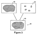
図3は、好ましい実施の形態に従って得られるさまざまな画像の図である。本発明の好ましい実施の形態において、2台のモニタ40及び57(図1を参照)が、肉眼で見える画像及び共焦顕微鏡画像に対してそれぞれ用いられる。通常の白色光画像上の蛍光画像のさまざまな部位が見られるように、通常の白色光画像及び肉眼で見える蛍光画像は最も好ましくは、単一画像を提供するために重ね合わされる。図3において理解されるように、画像80は、肉眼で見える白色光画像を表し、及び、画像82は、肉眼で見える蛍光性の画像を表す。両方の画像が一緒に単一画像83とみなされるように、画像はモニタ40の半分の画像レートによってさまざまな画像をモニタ40に切り替えることによってモニタ40の上に重ね合わされる。画像80及び82が単一画像を生成するために重ね合わされる方法は、任意の望ましい方法でも実行されうる。
FIG. 3 is an illustration of various images obtained in accordance with a preferred embodiment. In the preferred embodiment of the present invention, two
好ましい実施の形態において、別々のモニタが蛍光顕微鏡画像のために用いられるにもかかわらず、モニタ40の一部が蛍光顕微鏡画像を示すように、モニタの一部は重ね合わされた肉眼で見える画像を示すように、モニタ40がスプリットスクリーン・テクニックによってその画像に対して用いられることもできる。なお更なる実施の形態において、スプリットスクリーン・テクニックは、重ね合わされた画像83と同様に、別々の画像80及び82を示すために用いることができ、それからまた、顕微鏡画像であってもよい。なお更なる実施例において、3つの別々のモニタは、3つの異なる画像を示すために用いられうる。
In a preferred embodiment, even though separate monitors are used for the fluorescence microscope image, a portion of the monitor displays an image that is visible to the naked eye such that a portion of the
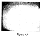
[実施例]
図4A、図4B及び図4Cは、それぞれ、図1のエンドスコープ10によって収集される、通常の白色光の肉眼で見える画像(図3の画像80を参照)、対応する肉眼で見える蛍光画像(図3の画像82を参照)及び共焦顕微鏡画像の実施例(グレイスケールにおいて再現される)である。これらの画像は、人間のコロンの一部であり、そして、Pharmalabブランドのナトリウム・フルオレセイン10%溶液のうちの5mLの形態の蛍光造影剤の静注によって下記の投与で収集される。
[Example]
FIGS. 4A, 4B and 4C respectively show a normal white light image (see
図5A及び図5Bは、それぞれ、図4A及び図4Bのオリジナルのカラーバージョンである。 5A and 5B are the original color versions of FIGS. 4A and 4B, respectively.
図4A及び図4Bの画像は、コロンの同じ部分であって、各辺約数センチメートルの領域を表す。 The images of FIGS. 4A and 4B represent the same part of the colon, representing an area about a few centimeters on each side.
図4Bの画像は、青色光の入射ビームを生じるために光源20の上に青色フィルタ22を配置することによって得られた。上述の通り、検出器30の異なるカラー・チップのための相対強度ゲインは、戻ってくる蛍光の検出を最大にして、任意の背景反射光の検出を減らすように調整された。具体的には、緑色のチップのゲインは、ほぼ530nmで信号を強化するために、青色及び赤色のチップのゲインに対して調整された。
The image of FIG. 4B was obtained by placing a
画像図4Bは、中心に拡散した明るい蛍光領域がある。この領域は、非常に異形成で、特異的に蓄積されたより多くのナトリウム・フルオレセインを有する。図4Bにおける小さく明るい外形は、コロンの表層から入射光のいくらかの反射から生じて、表層の輝きに達する加工品である。(実際、いくつかの閃光は、図4Aの形状においても明白でもある。) Image FIG. 4B has a bright fluorescent region diffused in the center. This region is very dysplastic and has more sodium fluorescein specifically accumulated. The small bright outline in FIG. 4B is a workpiece that results from some reflection of incident light from the surface of the colon and reaches the brightness of the surface. (In fact, some flashes are also evident in the shape of FIG. 4A.)
図4Cの画像は、図4A及び図4Bにおいて撮像される組織の一部である。この画像が図4A及び図4Bに対して拡大されるように、この視野はほぼ500μm×500μmである。入射光が、488nmでレーザー60によって生成され、戻り光は検出器68に影響を与える前にほぼ530nmのピークを有するナローバンドフィルタを通って、その結果、ナトリウム・フルオレセインによって発される蛍光だけが集められる。
The image of FIG. 4C is a portion of the tissue imaged in FIGS. 4A and 4B. The field of view is approximately 500 μm × 500 μm so that this image is magnified relative to FIGS. 4A and 4B. Incident light is generated by the
エンドスコープ10の焦点面は、実質的なゼロ(すなわち、組織の表層を撮像するために)から組織表面下の約250μmの深さまで可変的である。この例では、組織表面下のほぼ50μmの焦点面が、用いられた。従って、この画像の含有物は、構造体を示し、細胞形成異常の程度を示す。図4Bにおいて見られる反射率は、それが表面効果であるため、集められなかった。
The focal plane of the
本発明の趣旨及び範囲内の変形が当業者によって直ちに遂行されることができるので、本発明が先に例示として記載されている特定の実施の形態に限られていないことを理解すべきである。 It should be understood that the invention is not limited to the specific embodiments described above by way of example, as modifications within the spirit and scope of the invention can be readily accomplished by those skilled in the art. .
本発明における請求項及び上述の説明において、文脈で要求しているかさもなければ言語的又は必須的に暗示している場合を除いて、「含む(備える、具備する)」又は「含んでいる」又は「含んで」といった変形例の単語は、包括的な意味で用いられる。すなわち、上述の特徴の存在を特定するが、本発明の各種実施形態の更なる特徴の存在又は追加を排除しないために、使用される。 In the claims of the present invention and the above description, the description includes “includes” or “includes” unless the context requires or otherwise implies linguistically or essentially. Or the word of the modification like "includes" is used by the comprehensive meaning. That is, it is used to identify the presence of the features described above, but not to exclude the presence or addition of additional features of various embodiments of the invention.
更に、本願明細書における先行技術へのいかなる参照も、この種の先行技術が共通の一般知識の一部を形成するか又は形成したということを意味することを意図しない。 Furthermore, any reference to the prior art herein is not intended to imply that this type of prior art forms or forms part of common general knowledge.
10 エンドスコープ
12 挿入部
14 処理部
20 電球(バルブ)
22 フィルタホイール
30 検出器
40 モニタ
42 ライン
44 ファイバ
50 共焦ファイバ
55 共焦先端
52 レンズ・セット
60 レーザー
66 シングルモード・ファイバ・カプラー
68 第2の検出器
70 第1の導波管
72 第2の導波管
10
22
Claims (25)
反射光及び前記組織中に誘起された蛍光によって、前記組織からの肉眼で見える画像及び蛍光画像を検出するための第1の検出器と、
前記組織を光で照射するための第2の光源と、
前記第2の光源から前記組織への前記光を供給するための、及び、前記組織の蛍光顕微鏡画像を供給するための、共焦点顕微鏡導波管と、
前記共焦点顕微鏡導波管からの前記蛍光顕微鏡画像を検出するための第2の検出器と、を備え
前記第1の光源の光及び前記第2の光源の光は、異なる光路長に沿って前記組織に送信される、エンドスコープ。 A first light source for illuminating biological tissue;
A first detector for detecting a visible and fluorescent image from the tissue by reflected light and fluorescence induced in the tissue;
A second light source for irradiating the tissue with light;
A confocal microscope waveguide for supplying the light from the second light source to the tissue and for supplying a fluorescence microscope image of the tissue;
A second detector for detecting the fluorescence microscope image from the confocal microscope waveguide, wherein the light from the first light source and the light from the second light source are along different optical path lengths. An end scope sent to the organization.
前記エンドスコープの前記自由端で提供される更なるフィルタを備える、請求項7に記載のエンドスコープ。 In order to filter the light received by the second waveguide,
The endscope of claim 7, further comprising a further filter provided at the free end of the endscope.
前記第1の検出器及び前記第2の検出器の間に位置する、請求項7に記載のエンドスコープ。 In order to filter the light received by the second waveguide,
The endoscope of claim 7, located between the first detector and the second detector.
前記第1の検出器中の異なるカラー・チップに対する強度ゲインが、戻ってくる蛍光の検出を最大化して任意の背景反射光の検出を減少させるように調整されうる、請求項1に記載のエンドスコープ。 The first detector is connected to a processor, and the first detector comprises a plurality of different color chips;
The end of claim 1, wherein intensity gains for different color chips in the first detector can be adjusted to maximize detection of the returning fluorescence and reduce detection of any background reflected light. scope.
外生の造影剤を患者に適用すること、
前記組織を前記エンドスコープで照射すること、
前記エンドスコープによる前記組織中の光画像を前記エンドスコープで検出すること、
肉眼で見える蛍光性の画像を前記エンドスコープで検出すること、
前記組織中の共焦点蛍光顕微鏡画像を前記エンドスコープで検出すること、
を含む、方法。 A method of examining a patient's tissue using an endoscope,
Applying exogenous contrast media to the patient,
Irradiating the tissue with the endoscope;
Detecting an optical image in the tissue by the endoscope with the endoscope;
Detecting a fluorescent image visible to the naked eye with the endoscope;
Detecting a confocal fluorescence microscope image in the tissue with the endoscope;
Including a method.
前記方法は、フィルタパラメータ及び前記カラー検出器のゲインを、前記造影剤に対して、最大の励起及び発光ピークになるように、制御することを含む、請求項19に記載の方法。 The endoscope comprises a filter and a color detector,
20. The method of claim 19, wherein the method includes controlling filter parameters and gain of the color detector to achieve maximum excitation and emission peaks for the contrast agent.
前記組織の肉眼で見える蛍光画像が得られる肉眼蛍光モード、
前記組織の蛍光顕微鏡画像が得られる共焦点顕微鏡蛍光モード、を備える、エンドスコープ。 White light color operating mode, which gives a color image of the patient's tissue,
Macroscopic fluorescence mode in which a fluorescent image visible to the naked eye of the tissue is obtained;
An endoscope comprising a confocal microscope fluorescence mode from which a fluorescence microscope image of the tissue is obtained.
外生の造影剤を患者に適用すること、
患者の組織の白色光のカラー画像、肉眼で見える蛍光画像、及び、共焦点蛍光顕微鏡画像を1又は2以上得ること、を含む、方法。 A method for obtaining an image of a patient using a single endoscope,
Applying exogenous contrast media to the patient,
Obtaining one or more of a white light color image, a naked eye fluorescent image, and a confocal fluorescent microscope image of a patient's tissue.
Applications Claiming Priority (2)
| Application Number | Priority Date | Filing Date | Title |
|---|---|---|---|
| AU2004906759A AU2004906759A0 (en) | 2004-11-25 | Endoscope | |
| PCT/AU2005/001782 WO2006056014A1 (en) | 2004-11-25 | 2005-11-24 | Endoscope |
Publications (1)
| Publication Number | Publication Date |
|---|---|
| JP2008521453A true JP2008521453A (en) | 2008-06-26 |
Family
ID=36497672
Family Applications (1)
| Application Number | Title | Priority Date | Filing Date |
|---|---|---|---|
| JP2007541585A Pending JP2008521453A (en) | 2004-11-25 | 2005-11-24 | End scope |
Country Status (4)
| Country | Link |
|---|---|
| US (1) | US20080004495A1 (en) |
| EP (1) | EP1814434A4 (en) |
| JP (1) | JP2008521453A (en) |
| WO (1) | WO2006056014A1 (en) |
Cited By (3)
| Publication number | Priority date | Publication date | Assignee | Title |
|---|---|---|---|---|
| JP2011530082A (en) * | 2008-08-04 | 2011-12-15 | ユニバーシティ オブ ユタ リサーチ ファウンデーション | Application of dyes for confocal imaging of cellular microstructures |
| EP2546092A2 (en) | 2011-07-11 | 2013-01-16 | Delphi Technologies, Inc. | Electrical charging system having energy coupling arrangement for wireless energy transmission therebetween |
| JP2015114216A (en) * | 2013-12-12 | 2015-06-22 | 澁谷工業株式会社 | Content leakage inspection method and device |
Families Citing this family (8)
| Publication number | Priority date | Publication date | Assignee | Title |
|---|---|---|---|---|
| US8285015B2 (en) * | 2002-07-05 | 2012-10-09 | Lawrence Livermore Natioonal Security, LLC | Simultaneous acquisition of differing image types |
| WO2007132378A2 (en) * | 2006-05-09 | 2007-11-22 | Koninklijke Philips Electronics N. V. | Imaging system for three-dimensional imaging of the interior of an object |
| EP2162779B1 (en) | 2007-06-28 | 2013-08-07 | Koninklijke Philips Electronics N.V. | Lens system |
| US20090236541A1 (en) * | 2008-03-24 | 2009-09-24 | General Electric Company | System and Methods for Optical Imaging |
| EP2380482A1 (en) * | 2010-04-21 | 2011-10-26 | Koninklijke Philips Electronics N.V. | Extending image information |
| JP5604248B2 (en) * | 2010-09-28 | 2014-10-08 | 富士フイルム株式会社 | Endoscopic image display device |
| EP2636359B1 (en) * | 2011-08-15 | 2018-05-30 | Olympus Corporation | Imaging apparatus |
| CN104010558B (en) * | 2011-12-28 | 2017-03-01 | 奥林巴斯株式会社 | The method of work of fluorescence monitoring apparatus, fluorescence observing method and fluorescence monitoring apparatus |
Citations (5)
| Publication number | Priority date | Publication date | Assignee | Title |
|---|---|---|---|---|
| JPH01136629A (en) * | 1987-11-25 | 1989-05-29 | Olympus Optical Co Ltd | Endoscopic apparatus for fluorescent observation |
| JPH0397441A (en) * | 1989-09-08 | 1991-04-23 | Olympus Optical Co Ltd | Endoscope for fluorescent observation |
| JP2002345733A (en) * | 2001-05-29 | 2002-12-03 | Fuji Photo Film Co Ltd | Imaging device |
| JP2004154258A (en) * | 2002-11-05 | 2004-06-03 | Pentax Corp | Confocal endoscope |
| JP2004159924A (en) * | 2002-11-13 | 2004-06-10 | Olympus Corp | Endoscope |
Family Cites Families (24)
| Publication number | Priority date | Publication date | Assignee | Title |
|---|---|---|---|---|
| JPS5940830A (en) * | 1982-08-31 | 1984-03-06 | 浜松ホトニクス株式会社 | Apparatus for diagnosis of cancer using laser beam pulse |
| US4882619A (en) * | 1986-04-07 | 1989-11-21 | Olympus Optical Co., Ltd. | High resolution image pickup system with color dispersion means |
| JPS62247232A (en) * | 1986-04-21 | 1987-10-28 | Agency Of Ind Science & Technol | Fluorescence measuring apparatus |
| DE68929553T2 (en) * | 1988-07-13 | 2009-01-29 | Optiscan Pty. Ltd., Toorak | Confocal scanning microscope |
| JP3796635B2 (en) * | 1996-03-06 | 2006-07-12 | 富士写真フイルム株式会社 | Fluorescence detection device |
| US7179222B2 (en) * | 1996-11-20 | 2007-02-20 | Olympus Corporation | Fluorescent endoscope system enabling simultaneous achievement of normal light observation based on reflected light and fluorescence observation based on light with wavelengths in infrared spectrum |
| JP3853931B2 (en) * | 1997-10-02 | 2006-12-06 | オリンパス株式会社 | Endoscope |
| AUPP548298A0 (en) * | 1998-08-27 | 1998-09-17 | Optiscan Pty Limited | Compact confocal endoscope and endomicroscope method and apparatus |
| US6522906B1 (en) * | 1998-12-08 | 2003-02-18 | Intuitive Surgical, Inc. | Devices and methods for presenting and regulating auxiliary information on an image display of a telesurgical system to assist an operator in performing a surgical procedure |
| US6545260B1 (en) * | 1999-11-19 | 2003-04-08 | Olympus Optical Co., Ltd. | Light scanning optical device which acquires a high resolution two-dimensional image without employing a charge-coupled device |
| US6530882B1 (en) * | 2000-06-30 | 2003-03-11 | Inner Vision Imaging, L.L.C. | Endoscope having microscopic and macroscopic magnification |
| US6414779B1 (en) * | 2000-11-30 | 2002-07-02 | Opeical Biopsy Technologies, Inc. | Integrated angled-dual-axis confocal scanning endoscopes |
| JP2002209830A (en) * | 2001-01-16 | 2002-07-30 | Toshiba Corp | Endoscope and microscopic probe |
| EP1372486A2 (en) * | 2001-03-09 | 2004-01-02 | Lucid, Inc. | System and method for macroscopic and confocal imaging of tissue |
| US7172553B2 (en) * | 2001-05-16 | 2007-02-06 | Olympus Corporation | Endoscope system using normal light and fluorescence |
| US7179221B2 (en) * | 2002-03-28 | 2007-02-20 | Fuji Photo Film Co., Ltd. | Endoscope utilizing fiduciary alignment to process image data |
| WO2003090613A1 (en) * | 2002-04-26 | 2003-11-06 | Optiscan Pty Ltd | Laser scanning confocal microscope with fibre bundle return |
| US7252634B2 (en) * | 2002-11-05 | 2007-08-07 | Pentax Corporation | Confocal probe having scanning mirrors mounted to a transparent substrate in an optical path of the probe |
| US20040097791A1 (en) * | 2002-11-13 | 2004-05-20 | Olympus Corporation | Endoscope |
| JP2004180857A (en) * | 2002-12-02 | 2004-07-02 | Olympus Corp | Endoscope remote diagnostic system |
| JP4019417B2 (en) * | 2003-01-14 | 2007-12-12 | ソニー株式会社 | Image processing apparatus and method, recording medium, and program |
| US7267647B2 (en) * | 2003-02-10 | 2007-09-11 | Pentax Corporation | Endoscope |
| US7267648B2 (en) * | 2003-03-31 | 2007-09-11 | Olympus Corporation | Magnifying image pickup unit for an endoscope, an endoscope for in vivo cellular observation that uses it, and endoscopic, in vivo cellular observation methods |
| US20040230098A1 (en) * | 2003-05-14 | 2004-11-18 | Inner Vision Imaging, L.L.C. | Endoscope illumination system |
-
2005
- 2005-11-24 WO PCT/AU2005/001782 patent/WO2006056014A1/en active Application Filing
- 2005-11-24 JP JP2007541585A patent/JP2008521453A/en active Pending
- 2005-11-24 EP EP05804562A patent/EP1814434A4/en not_active Withdrawn
-
2007
- 2007-05-24 US US11/753,506 patent/US20080004495A1/en not_active Abandoned
Patent Citations (5)
| Publication number | Priority date | Publication date | Assignee | Title |
|---|---|---|---|---|
| JPH01136629A (en) * | 1987-11-25 | 1989-05-29 | Olympus Optical Co Ltd | Endoscopic apparatus for fluorescent observation |
| JPH0397441A (en) * | 1989-09-08 | 1991-04-23 | Olympus Optical Co Ltd | Endoscope for fluorescent observation |
| JP2002345733A (en) * | 2001-05-29 | 2002-12-03 | Fuji Photo Film Co Ltd | Imaging device |
| JP2004154258A (en) * | 2002-11-05 | 2004-06-03 | Pentax Corp | Confocal endoscope |
| JP2004159924A (en) * | 2002-11-13 | 2004-06-10 | Olympus Corp | Endoscope |
Cited By (7)
| Publication number | Priority date | Publication date | Assignee | Title |
|---|---|---|---|---|
| JP2011530082A (en) * | 2008-08-04 | 2011-12-15 | ユニバーシティ オブ ユタ リサーチ ファウンデーション | Application of dyes for confocal imaging of cellular microstructures |
| EP2546092A2 (en) | 2011-07-11 | 2013-01-16 | Delphi Technologies, Inc. | Electrical charging system having energy coupling arrangement for wireless energy transmission therebetween |
| EP2546953A2 (en) | 2011-07-11 | 2013-01-16 | Delphi Technologies, Inc. | Electrical charging system having energy coupling arrangement for wireless energy transmission therebetween. |
| EP2546093A2 (en) | 2011-07-11 | 2013-01-16 | Delphi Technologies, Inc. | Electrical charging system having energy coupling arrangement for wireless energy transmission therebetween |
| EP2546950A2 (en) | 2011-07-11 | 2013-01-16 | Delphi Technologies, Inc. | Electrical charging system having energy coupling arrangement for wireless energy transmission therebetween. |
| EP2546951A2 (en) | 2011-07-11 | 2013-01-16 | Delphi Technologies, Inc. | Electrical charging system having energy coupling arrangement for wireless energy transmission therebetween |
| JP2015114216A (en) * | 2013-12-12 | 2015-06-22 | 澁谷工業株式会社 | Content leakage inspection method and device |
Also Published As
| Publication number | Publication date |
|---|---|
| EP1814434A1 (en) | 2007-08-08 |
| US20080004495A1 (en) | 2008-01-03 |
| WO2006056014A1 (en) | 2006-06-01 |
| EP1814434A4 (en) | 2009-10-21 |
Similar Documents
| Publication | Publication Date | Title |
|---|---|---|
| JP2008521453A (en) | End scope | |
| US10314490B2 (en) | Method and device for multi-spectral photonic imaging | |
| US8021295B2 (en) | Endoscope system and observation method using the same | |
| JP4217403B2 (en) | System for characterization and mapping of tissue lesions | |
| US8382812B2 (en) | Apparatus for photodynamic therapy and photodetection | |
| JP3694667B2 (en) | Apparatus and method for projecting diseased tissue images using integrated autofluorescence | |
| US9345389B2 (en) | Additional systems and methods for providing real-time anatomical guidance in a diagnostic or therapeutic procedure | |
| JP3654325B2 (en) | Fluorescence detection device | |
| JP5208430B2 (en) | Fluorescence observation device for living tissue | |
| US20070213593A1 (en) | Endoscope system | |
| US20100234684A1 (en) | Multifunctional endoscopic device and methods employing said device | |
| US20080027286A1 (en) | Removable Filter Apparatus and Endoscope Apparatus | |
| JPH0654792A (en) | Image pickup device | |
| US20100268091A1 (en) | Fluorescence imaging apparatus and endoscope apparatus | |
| JP2003204924A (en) | Fluorescent endoscope system and diagnostic region image-carving method utilizing the same | |
| JP2001299676A (en) | Method and system for detecting sentinel lymph node | |
| JP2007505645A (en) | Automated endoscope device, diagnostic method and usage | |
| JP2008148791A (en) | Endoscope system | |
| JP2006340796A (en) | Sentinel lymph node detection system | |
| JP2008043383A (en) | Fluorescence observation endoscope instrument | |
| CA2335246A1 (en) | Detection of cancer using cellular autofluorescence | |
| Wagnieres et al. | Frequency-domain fluorescence lifetime imaging for endoscopic clinical cancer photodetection: apparatus design and preliminary results | |
| JP2005312979A (en) | Imaging device | |
| Papayan et al. | Video-endoscopy system for photodynamic theranostics of central lung cancer | |
| EP2228003A1 (en) | Multifunctional endoscopic device and methods employing said device |
Legal Events
| Date | Code | Title | Description |
|---|---|---|---|
| A621 | Written request for application examination |
Free format text: JAPANESE INTERMEDIATE CODE: A621 Effective date: 20080808 |
|
| A977 | Report on retrieval |
Free format text: JAPANESE INTERMEDIATE CODE: A971007 Effective date: 20110419 |
|
| A131 | Notification of reasons for refusal |
Free format text: JAPANESE INTERMEDIATE CODE: A131 Effective date: 20110426 |
|
| A601 | Written request for extension of time |
Free format text: JAPANESE INTERMEDIATE CODE: A601 Effective date: 20110726 |
|
| A602 | Written permission of extension of time |
Free format text: JAPANESE INTERMEDIATE CODE: A602 Effective date: 20110802 |
|
| A601 | Written request for extension of time |
Free format text: JAPANESE INTERMEDIATE CODE: A601 Effective date: 20110825 |
|
| A602 | Written permission of extension of time |
Free format text: JAPANESE INTERMEDIATE CODE: A602 Effective date: 20110901 |
|
| A521 | Request for written amendment filed |
Free format text: JAPANESE INTERMEDIATE CODE: A523 Effective date: 20111026 |
|
| A02 | Decision of refusal |
Free format text: JAPANESE INTERMEDIATE CODE: A02 Effective date: 20120306 |