JP2008519743A - Equipment for storing and dispensing packages - Google Patents
Equipment for storing and dispensing packages Download PDFInfo
- Publication number
- JP2008519743A JP2008519743A JP2007540719A JP2007540719A JP2008519743A JP 2008519743 A JP2008519743 A JP 2008519743A JP 2007540719 A JP2007540719 A JP 2007540719A JP 2007540719 A JP2007540719 A JP 2007540719A JP 2008519743 A JP2008519743 A JP 2008519743A
- Authority
- JP
- Japan
- Prior art keywords
- path
- package
- area
- packages
- region
- Prior art date
- Legal status (The legal status is an assumption and is not a legal conclusion. Google has not performed a legal analysis and makes no representation as to the accuracy of the status listed.)
- Pending
Links
Images


Classifications
-
- B—PERFORMING OPERATIONS; TRANSPORTING
- B65—CONVEYING; PACKING; STORING; HANDLING THIN OR FILAMENTARY MATERIAL
- B65G—TRANSPORT OR STORAGE DEVICES, e.g. CONVEYORS FOR LOADING OR TIPPING, SHOP CONVEYOR SYSTEMS OR PNEUMATIC TUBE CONVEYORS
- B65G1/00—Storing articles, individually or in orderly arrangement, in warehouses or magazines
- B65G1/02—Storage devices
- B65G1/04—Storage devices mechanical
- B65G1/06—Storage devices mechanical with means for presenting articles for removal at predetermined position or level
- B65G1/08—Storage devices mechanical with means for presenting articles for removal at predetermined position or level the articles being fed by gravity
-
- B—PERFORMING OPERATIONS; TRANSPORTING
- B65—CONVEYING; PACKING; STORING; HANDLING THIN OR FILAMENTARY MATERIAL
- B65G—TRANSPORT OR STORAGE DEVICES, e.g. CONVEYORS FOR LOADING OR TIPPING, SHOP CONVEYOR SYSTEMS OR PNEUMATIC TUBE CONVEYORS
- B65G1/00—Storing articles, individually or in orderly arrangement, in warehouses or magazines
- B65G1/02—Storage devices
- B65G1/04—Storage devices mechanical
- B65G1/137—Storage devices mechanical with arrangements or automatic control means for selecting which articles are to be removed
- B65G1/1373—Storage devices mechanical with arrangements or automatic control means for selecting which articles are to be removed for fulfilling orders in warehouses
- B65G1/1376—Storage devices mechanical with arrangements or automatic control means for selecting which articles are to be removed for fulfilling orders in warehouses the orders being assembled on a commissioning conveyor
-
- G—PHYSICS
- G06—COMPUTING; CALCULATING OR COUNTING
- G06Q—INFORMATION AND COMMUNICATION TECHNOLOGY [ICT] SPECIALLY ADAPTED FOR ADMINISTRATIVE, COMMERCIAL, FINANCIAL, MANAGERIAL OR SUPERVISORY PURPOSES; SYSTEMS OR METHODS SPECIALLY ADAPTED FOR ADMINISTRATIVE, COMMERCIAL, FINANCIAL, MANAGERIAL OR SUPERVISORY PURPOSES, NOT OTHERWISE PROVIDED FOR
- G06Q10/00—Administration; Management
- G06Q10/08—Logistics, e.g. warehousing, loading or distribution; Inventory or stock management
-
- G—PHYSICS
- G16—INFORMATION AND COMMUNICATION TECHNOLOGY [ICT] SPECIALLY ADAPTED FOR SPECIFIC APPLICATION FIELDS
- G16H—HEALTHCARE INFORMATICS, i.e. INFORMATION AND COMMUNICATION TECHNOLOGY [ICT] SPECIALLY ADAPTED FOR THE HANDLING OR PROCESSING OF MEDICAL OR HEALTHCARE DATA
- G16H20/00—ICT specially adapted for therapies or health-improving plans, e.g. for handling prescriptions, for steering therapy or for monitoring patient compliance
- G16H20/10—ICT specially adapted for therapies or health-improving plans, e.g. for handling prescriptions, for steering therapy or for monitoring patient compliance relating to drugs or medications, e.g. for ensuring correct administration to patients
- G16H20/13—ICT specially adapted for therapies or health-improving plans, e.g. for handling prescriptions, for steering therapy or for monitoring patient compliance relating to drugs or medications, e.g. for ensuring correct administration to patients delivered from dispensers
Abstract
Description
本発明は物品を、小型のパッケージ(特に医薬品パッケージだけに限らない)を自動的に保管及び取り出すための装置に関するものである。 The present invention relates to an apparatus for automatically storing and retrieving articles in small packages (not limited to pharmaceutical packages in particular).
医薬品などを保管しておき、初期の要求を満たした後に人間の介在を必要とせずに取り出し及び払い出しを行う自動化薬局が当該技術分野では公知である。一般的に、このようなシステムは、パッケージが保管されている棚のラックの位置を記憶したデータベースに接続されたロボットアームを備えている。特定のパッケージの要求を受け取ると、ロボットアームは、的確な位置へ移動して目的とするパッケージを取り出し、そのパッケージをディスペンシング・シュートまで移送する。 Automated pharmacies are known in the art that store pharmaceuticals, etc., and that can be removed and dispensed without human intervention after meeting initial requirements. Typically, such a system includes a robotic arm connected to a database that stores the position of the rack of shelves in which the packages are stored. Upon receiving a request for a specific package, the robot arm moves to the correct position, takes out the target package, and transfers the package to the dispensing chute.
このようなシステムのアウトプット速度の上限は、ロボットアームの移動速度と、ロボットアームのスイープ範囲(ロボットアームがカバー可能な範囲)とによって制限される。ロボットアームの数を増やすことによって、アウトプット速度が向上されることは明らかである。しかし、その場合は、コストが著しく増大するという問題がある。また、複数のロボットアームを互いに密接に連係させる必要があるので、システムの複雑さが増すという問題もある。 The upper limit of the output speed of such a system is limited by the moving speed of the robot arm and the sweep range of the robot arm (the range that the robot arm can cover). Obviously, increasing the number of robot arms improves the output speed. However, in that case, there is a problem that the cost is remarkably increased. In addition, since it is necessary to closely link a plurality of robot arms, there is a problem that the complexity of the system increases.
さらに、棚スペースは、パッケージ内の医薬品の種類と前記パッケージの棚における保管位置とが相関しない並べ方で、動的に配置される傾向にある。したがって、医薬品の種類と、その医薬品の取り出し及び払い出しに要する時間との間には、相互関係は存在しない。 Furthermore, the shelf space tends to be dynamically arranged in such a way that the types of medicines in the package and the storage position on the shelf of the package do not correlate. Therefore, there is no correlation between the type of medicine and the time required for taking out and dispensing the medicine.
当該技術分野では、ある種類及び大きさの医薬品パッケージが他のものよりも頻繁に要求されることが認識されている。それらは、当該技術分野では、「売れ筋の商品(fast mover)」と呼ばれている。WO03/010073には、棚に売れ筋の商品のための別の領域を設け、前記領域のそれぞれに専用のロボットアームを設置することが開示されている。前記専用のロボットアームは、前記棚の反対側に設けられ、メインロボットアームに干渉されることなく、売れ筋の商品をより迅速に取り出すために、前記領域からパッケージの取り出しだけを行う。 It is recognized in the art that certain types and sizes of pharmaceutical packages are required more frequently than others. They are called “fast movers” in the art. In WO03 / 010073, it is disclosed that a separate area for a hot-selling product is provided on a shelf, and a dedicated robot arm is installed in each of the areas. The dedicated robot arm is provided on the opposite side of the shelf and only removes the package from the area in order to take out the hot selling product more quickly without being interfered by the main robot arm.
しかしながら、この従来の構造には、いくつかの重大な欠点がある。第1に、取り出しは依然としてロボットアームにより行われるので、払い出されるパッケージを掴むためには、棚の適切なポイントに2次元に変換する必要がある。また、従来の構造では、払い出し時間は、依然として同じオーダーである。 However, this conventional structure has several significant drawbacks. First, since removal is still performed by the robotic arm, in order to grab the package to be dispensed, it needs to be converted in two dimensions to the appropriate point on the shelf. In the conventional structure, the payout time is still in the same order.
第2に、さらなるロボットアームを追加すると、前述したように、コストが増大する。さらに、この余分な費用は、拡張された特定の装置として追加される各モジュールについて生じる。 Secondly, adding additional robot arms increases the cost, as described above. In addition, this extra cost is incurred for each module added as an extended specific device.
本発明の目的は、上述したような構造を改良することである。本発明の第1の特徴は、複数のパッケージを保管及び払い出すための装置であって、保管及び把持デバイスでアクセス可能な複数の棚を含む第1の領域と、各々が独立した排出手段を有する、各々が複数のパッケージを受け取るための複数の経路を含む第2の領域とを備え、保管及び把持デバイスが第2の領域の経路を満たすように構成され、第2の領域から排出されたパッケージを移動させるための搬送手段をさらに備える装置を提供することである。 The object of the present invention is to improve the structure as described above. A first feature of the present invention is an apparatus for storing and dispensing a plurality of packages, comprising a first region including a plurality of shelves accessible by a storage and gripping device, and an independent discharging means. And a second area comprising a plurality of paths each for receiving a plurality of packages, wherein the storage and gripping device is configured to fill the path of the second area and ejected from the second area It is to provide an apparatus further comprising transport means for moving the package.
一般的に、各経路は独立した排出機構を含むものである。 In general, each path includes an independent discharge mechanism.
従って、本発明は、保管及び払い出しシステムが、第2の保管領域で追加のロボットアームを利用するものではなく、第2の領域の各経路が独立してコンベヤーにパッケージをアウトプットできるように提供されるものであることが当業者には明らかであろう。このようなシステムは、パッケージを極めて迅速に、並行してアウトプットすることを可能にする。さらに、第2の領域、即ち、経路領域はモジュール形式で容易に作ることができるため、システムの拡張が容易である。例えば、共通のコンベヤーを備えるモジュール形式又は各モジュールが、パッケージをモジュールの端部まで搬送して、近接したモジュールのコンベヤー又は、追加のコンベヤー或いはディスペンシング・シュートなどの下流側の払い出しシステムに移動させるようなコンベヤーを備えるモジュール形式などがある。 Accordingly, the present invention provides that the storage and dispensing system does not utilize additional robotic arms in the second storage area, so that each path in the second area can independently output a package to the conveyor. It will be apparent to those skilled in the art that Such a system allows packages to be output very quickly and in parallel. Furthermore, since the second area, that is, the path area can be easily created in a module form, the system can be easily expanded. For example, a module type or each module with a common conveyor transports the package to the end of the module and moves it to a nearby module conveyor or a downstream dispensing system such as an additional conveyor or dispensing chute. There is a module type equipped with such a conveyor.
経路領域から排出されたパッケージを受け取るコンベヤーの構造は、複数の異なるパッケージが同時に必要な場合、例えば、1つの処方箋で必要な場合又は病棟回診用の注文に応じる場合など、搬送手段が一時的にバッファのような機能を果たし得ることを理解されたい。パッケージを一緒に集め、搬送システム又は搬送地点まで同時に搬送することにより、各パッケージが一つ一つ順に搬送地点まで搬送される従来技術の構造と比較して、著しく時間を節約することができる。この構造は、当然のことながら、保管及び取り出し装置と、最終的な搬送先、例えば、薬局の受付との間の距離が比較的長い場合に有用である。この構造は、通常、薬局で働く人に作業スペースの制限をなくし、装置が動作する際に生じる騒音から距離をおけるようにすることから望ましい。 The structure of the conveyor that receives the package ejected from the route area is such that when several different packages are needed at the same time, for example when needed with one prescription or when ordering for a ward round, It should be understood that it can serve as a buffer. By collecting the packages together and transporting them simultaneously to the transport system or transport point, significant time can be saved compared to prior art structures where each package is transported one by one to the transport point. This structure is of course useful when the distance between the storage and retrieval device and the final transport destination, for example a pharmacy reception, is relatively long. This structure is usually desirable because it eliminates work space limitations for pharmacy workers and keeps away from the noise generated when the device is operating.
本発明の装置が十分に高い位置に配置された場合、パッケージが経路領域の経路から排出されて、コンベヤーに落下した後でさえ、依然として装置は、最終搬送機構、例えば、シュートにとって十分に高い位置にある。好適な実施形態において、しかし、経路領域から排出されたパッケージを持上げて、所定の上昇高さにあるコンベヤーの上に置くためのリフト手段が備えられている。例えば、好適な実施形態において、リフト手段は経路領域に近接して備えられ、経路から排出されたパッケージが搬送手段によってリフト手段まで搬送されるように配置される。この形態は、また、パッケージを取り出すために1つ又は複数のロボットアームを備える構造と比較して、装置の構造及び最終搬送地点まで搬送するための配置場所に関して柔軟に対応することができ、しかも著しくコストを増加することもないことから有用である。 If the device of the present invention is placed high enough, the device will still be high enough for the final transport mechanism, e.g. chute, even after the package has been ejected from the path in the path area and dropped onto the conveyor. It is in. In a preferred embodiment, however, lift means are provided for lifting the package ejected from the path area and placing it on a conveyor at a predetermined elevated height. For example, in a preferred embodiment, the lift means is provided proximate to the path area and is arranged such that a package discharged from the path is transported to the lift means by the transport means. This configuration can also flexibly deal with the structure of the device and the placement location for transporting to the final transport point, compared to a structure with one or more robot arms to take out the package, and This is useful because it does not significantly increase the cost.
さらに、1つのリフトが複数の経路モジュールに対応するように備えられることもできる。実際、リフトを追加することなく、さらに経路モジュールを現在のシステムに追加することもできる。リフト手段は、搬送手段に加えて又は搬送手段の代わりに、複数のパッケージを集めて、同時に搬送することを可能にするようなバッファとして機能しても良く、パッケージを1つずつ最終搬送地点まで搬送するものと比較して、アウトプット速度が向上することを理解されたい。 Furthermore, one lift can be provided to accommodate a plurality of path modules. In fact, more route modules can be added to the current system without adding a lift. The lifting means may function as a buffer that allows a plurality of packages to be collected and transported simultaneously in addition to or in place of the transporting means. It should be understood that the output speed is improved compared to the transport.
リフトは、パッケージを最終搬送システム、例えば、シュートなどに排出するように構成されることが望ましい。実際、実施形態によっては、装置が複数の異なる最終搬送地点を含むことが望ましく、例えば、複数のオペレータに供給するようにすることが望ましい。その場合、リフトは複数の最終搬送機構の1つにパッケージを移送し得る。例えば、ディスペンシング・シュートは、リフト手段の移動経路に従って異なる高さに配置されることもでき、リフト手段の上に置かれたパッケージを排出するのに適した高さまで上昇させることによって、パッケージを所望の最終搬送地点に選択的に払い出されるようにすることもできる。 The lift is preferably configured to eject the package to a final transport system, such as a chute. Indeed, in some embodiments, it may be desirable for the apparatus to include a plurality of different final transport points, for example, to supply a plurality of operators. In that case, the lift may transfer the package to one of a plurality of final transport mechanisms. For example, the dispensing chute can be placed at different heights according to the path of movement of the lifting means, and by raising the package to a height suitable for discharging the package placed on the lifting means, It is also possible to selectively pay out to a desired final conveyance point.
リフト手段は、パッケージを所定の異なる高さまで上昇させ、パッケージを更なる搬送システム、例えば、アウトプット・シュートなどに搬送する、又はパッケージを取出せるように構成すべきものである。リフト手段は、様々な構造をとることが可能である。1つの使用し得る構造では、搬送手段、又は搬送手段の少なくとも一部が、必要に応じて上昇及び下降可能に構成される。この構成は、スペース効率を含め、いくつかの有用な点がある。また、単に高い位置まで上昇を行うプラットフォームが備えられることもできる。 The lifting means should be configured to raise the package to different predetermined heights so that the package can be transported to a further transport system, such as an output chute, or removed. The lift means can take various structures. In one usable structure, the conveying means or at least a part of the conveying means is configured to be able to be raised and lowered as necessary. This configuration has several useful points, including space efficiency. It can also be provided with a platform that simply rises to a higher position.
パッケージの排出は、所望の高さにおいて様々な方法で実行できる。昇降プラットフォームは、リフトの所望の出口側の側面から遠ざかるに従って上向きに傾斜し得る。ドア又はゲートが、プラットフォーム自身に取り付けられる、又はプラットフォームと対向する面の装置の壁に取り付けられる。また、ドア/ゲートの有無に関係なく、所望の高さに到達したときのみ、プラットフォームが傾けられるようにすることもできる。1つの使用し得る実施例は、プラットフォームが両側から吊るされたものであり、両側の吊り下げ高さに差があるとき、プラットフォームが傾けられるようにすることもできる。 Package ejection can be performed in various ways at the desired height. The lifting platform can tilt upward as it moves away from the desired exit side of the lift. A door or gate is attached to the platform itself or to the device wall on the side facing the platform. Also, the platform can be tilted only when the desired height is reached, with or without a door / gate. One possible embodiment is that the platform is suspended from both sides, and the platform can be tilted when there is a difference in the suspension heights on both sides.
本発明では、保管及び取り出しデバイスを用いる第1の領域からのアウトプットは、第2の領域、即ち、経路領域からのアウトプットと完全に独立するようにすることもできる。しかしながら、少なくとも一部の好適な実施形態では、第1及び第2の領域から各々払い出されたパッケージが移送される経路は、少なくとも一部が共通している。実際、共通の搬送手段が使用されることもでき、それによって、両方の領域からのパッケージが最終搬送地点まで搬送される。この形態は、1つの注文を取りまとめるために必要なパッケージを、第1及び第2の領域の間で分配し得るため、コンベヤーのバッファ機能の効果を発揮させやすい。しかしながら、好適な構成では、第1及び第2の領域から払い出されるパッケージは、少なくともその経路の一部において、互いに別々の経路を用いるため、全体のアウトプット速度を遅くさせるようなボトルネックとなる問題の発生を防止しやすくしている。 In the present invention, the output from the first region using the storage and retrieval device can also be made completely independent of the output from the second region, i.e. the path region. However, in at least some preferred embodiments, at least part of the path through which the package delivered from each of the first and second regions is transferred is common. In fact, a common transport means can also be used, whereby packages from both areas are transported to the final transport point. Since this form can distribute the package required to collect one order between the first and second regions, it is easy to exert the effect of the buffer function of the conveyor. However, in a preferred configuration, packages delivered from the first and second areas use separate paths at least in part of the path, which creates a bottleneck that slows the overall output speed. It helps prevent problems.
本発明に基づく装置は、経路領域から排出されたパッケージを、搬送手段に直接落下させるように構成することもできる。しかしながら、この構成は落下を強制するため、結果としてパッケージ又はその中の内容物にダメージを与える可能性が大きくなるため好ましくない。好適な実施形態では、従って、落下するパッケージを受け取るための衝撃を和らげる緩衝領域が備えられ、パッケージはそこからコンベヤーの上に落とされる、又は更に短い距離を滑ってコンベヤーの上に搬送される。これは多くの実施方法で実施可能であるが、ゆるく吊るされたシート状の材料、例えば、パッケージが大きく跳ね返らず、落下するパッケージの衝撃を和らげることができるような繊維を用いることが好ましい。 The device according to the invention can also be configured to drop the package discharged from the path area directly onto the transport means. However, this configuration is not preferred because it forces a drop and consequently increases the possibility of damage to the package or its contents. In a preferred embodiment, therefore, a buffering area is provided to cushion the impact for receiving the falling package, from which the package is dropped onto the conveyor or slid over a shorter distance onto the conveyor. This can be done in many ways, but it is preferable to use a loosely suspended sheet-like material, for example, a fiber that does not bounce off the package and can mitigate the impact of the falling package.
好適な実施形態によっては、2つの別々の経路領域を備えるようにすることもでき、共通の緩衝領域又は好ましくは各々緩衝領域を有して、共通の搬送手段に供給するようにすることもできる。 Depending on the preferred embodiment, it can also be provided with two separate path areas, or can have a common buffer area, or preferably each buffer area, to be fed to a common transport means. .
2つ又はそれより多くの別々の経路領域を備えることは、一連の好適な実施形態の一般的な特徴である。当然のことながら、本発明では、これら経路領域の1つは、上述したような本発明の装置の第2の領域、即ち、経路領域である。従って、それが第1の領域の棚にアクセスする保管及び取り出しデバイスによって満たされるように構成される。様々な追加の経路領域が、同じ保管及び取り出しデバイスによって満たされるように備えられることもできる。また、1つ又は複数の追加の保管及び取り出しデバイスが備えられることもできる。また、1つ又は複数の追加の経路領域が、手動で満たされるように構成されることもできる。この構成は、他の経路領域での故障の発生に対する手動バックアップを可能にする、及び/又はインプット速度を速くするため、システムにパッケージを入れることを手動で補えるようにする。 Providing two or more separate path regions is a general feature of a series of preferred embodiments. Of course, in the present invention, one of these path areas is the second area of the apparatus of the present invention as described above, ie the path area. Thus, it is configured to be filled by a storage and retrieval device that accesses the shelf of the first region. Various additional path areas can also be provided to be filled by the same storage and retrieval device. One or more additional storage and retrieval devices can also be provided. One or more additional path regions can also be configured to be filled manually. This configuration allows manual backup for failure occurrences in other path areas and / or manually compensates for packaging into the system to increase input speed.
複数の経路領域が備えられている場合、これら経路領域は、共通のリフト手段によってパッケージが供給されることが望ましい。しかし、能力又はバックアップの理由から、1つ以上のリフトを備えて、各リフトが各経路領域にパッケージを供給できるようにすることもできる。 In the case where a plurality of route areas are provided, it is desirable that the package is supplied to these route areas by a common lift means. However, for capacity or backup reasons, one or more lifts may be provided so that each lift can supply a package to each path area.
各経路に備えられている排出手段は、様々な利便性の高い特定の形態をしていて良く、例えば、各経路の最前部は、その経路の前方から、その最前部にあるパッケージを傾けて落とす又は放出するようにしながら、他のパッケージは排出されないようにし、その後新たなパッケージが最前部に受け取られるように、残りのパッケージが経路を滑り降りることができるように構成することもできる。 The discharging means provided in each route may take various convenient and specific forms. For example, the front part of each route is inclined from the front of the route by the package at the front part. It can also be configured to allow the remaining packages to slide down the path so that other packages are not ejected while being dropped or released, and then a new package is received at the front.
特に好適な一連の実施形態では、排出手段は、パッケージを受け取る第1の位置から、パッケージを排出する第2の位置までピボットするように構成されたピボット部材を含むものであり、ピボット部材は、第2の位置において、追加のパッケージを受け取るのを阻止するように構成される。 In a particularly preferred series of embodiments, the ejecting means includes a pivot member configured to pivot from a first position for receiving the package to a second position for ejecting the package, the pivot member comprising: In the second position, configured to prevent receiving additional packages.
このような構成は、それ自体が新規で独創的であることから、本発明の更なる特徴は、複数のパッケージを受け取るための経路と、経路から1つずつパッケージを排出するための排出手段とを提供することであり、前記排出手段が、パッケージを受け取る第1の位置から、パッケージを排出する第2の位置までピボットするように構成されたピボット部材を含み、前記ピボット部材は、第2の位置において、追加のパッケージを受け取るのを阻止するように構成されることである。 Since such a configuration is novel and original in itself, a further feature of the present invention is that a path for receiving a plurality of packages and a discharging means for discharging the packages one by one from the path. Wherein the ejecting means includes a pivot member configured to pivot from a first position for receiving the package to a second position for ejecting the package, the pivot member comprising: In position, it is configured to prevent receiving additional packages.
これは同期アクチュエータ又は規定された時間だけ正確に作動するアクチュエータを用いるような複雑な構成を必要とすることなく、容易かつ確実に、パッケージを1つずつ排出することができる点で有用である。 This is useful in that the packages can be easily and reliably discharged one by one without the need for a complex configuration such as using a synchronous actuator or an actuator that operates accurately for a specified time.
上述したような本発明の特徴は、1つのパッケージが排出されて、ピボット部材が第1の位置に戻ると、次のパッケージがピボット部材によって受け取られるように、経路に残っているパッケージが構成されることである。この構成は、様々な適当な力、例えば、ばねを用いて行うことができるが、経路を傾斜させ、重力によって、パッケージを経路に沿ってピボット部材の方に向かって移動させることが好ましい。 A feature of the invention as described above is that the package remaining in the path is configured so that when one package is ejected and the pivot member returns to the first position, the next package is received by the pivot member. Is Rukoto. This configuration can be accomplished using a variety of suitable forces, such as springs, but it is preferable to tilt the path and move the package along the path toward the pivot member by gravity.
ピボット部材は、第1の位置において、追加のパッケージを受け取るのを阻止するように構成されることもできる。この構成は、ピボット部材がパッケージを充填される第3の位置を必要とし、パッケージは両側から持上げられてピボット部材に充填される。しかし、ピボット部材は第1の位置でパッケージを受け取ることができるように構成されることが好ましい。 The pivot member may also be configured to prevent receiving additional packages in the first position. This configuration requires a third position where the pivot member is filled with the package, and the package is lifted from both sides to fill the pivot member. However, the pivot member is preferably configured to receive the package in the first position.
ピボット部材は、好ましくはフロントアーム及びリアアームを含むものであり、フロントアームは、第1の位置においてパッケージの排出を防ぎ、第2の位置においてパッケージが排出されるように十分に引っ込むようなものである。第2のアームは、好ましくは、第1の位置において格納し得るものである。結果として、この構造はエスケープメント機構に多少類似したものであることを理解されたい。 The pivot member preferably includes a front arm and a rear arm, such that the front arm is sufficiently retracted to prevent ejection of the package in the first position and to eject the package in the second position. is there. The second arm is preferably one that can be retracted in the first position. As a result, it should be understood that this structure is somewhat similar to the escapement mechanism.
排出手段は、様々な適切な作動手段、例えば、モータ、電磁石、ソレノイドなどによって動作し得る。しかしながら、本出願人は特に利便性が高く、かつ簡素な構造を発明した。好適な実施形態では、排出手段は、熱応答する作動手段によって動作させる。熱応答作動手段は、それが異なる形状を構成するように加熱し、それによって、排出手段を移動させるように備えられる。熱応答作動手段は、単に構造体が膨張することによって必要な動作を得ることができるようなものを含み、それは例えば、バイメタル素子である。好ましくは、それは形状記憶材料を含む。そのような材料は良く知られたものであり、所定の温度まで加熱されると事前に形成された形状を構成するという特性を持っている。一部の樹脂もこの現象を示すが、本発明では形状記憶合金を使用することが好ましい。加熱手段は、形状記憶合金素子を自己加熱させるように、少なくとも形状記憶合金素子の一部に電流を通過させる手段を含むようなものであることが好ましい。 The ejecting means may be operated by various suitable actuating means such as motors, electromagnets, solenoids and the like. However, the applicant has invented a particularly convenient and simple structure. In a preferred embodiment, the evacuation means is operated by a thermally responsive actuation means. The thermal response actuating means is provided to heat so that it constitutes a different shape, thereby moving the discharge means. Thermally responsive actuation means include such that the required action can be obtained simply by expanding the structure, for example a bimetallic element. Preferably it comprises a shape memory material. Such materials are well known and have the property of forming a pre-formed shape when heated to a predetermined temperature. Although some resins also exhibit this phenomenon, it is preferable to use a shape memory alloy in the present invention. Preferably, the heating means includes means for passing an electric current through at least a part of the shape memory alloy element so as to self-heat the shape memory alloy element.
排出手段、例えば、好ましくはピボット部材は、重力によって待機位置に戻るように、又は能動的に待機位置に移動するように構成し得る。しかし、ピボット部材は待機位置に弾性的に付勢されることが好ましい。ピボット部材を備える好適な実施形態では、待機位置は第1の位置とも呼ばれる。 The discharge means, for example, preferably the pivot member, may be configured to return to the standby position by gravity or actively move to the standby position. However, it is preferable that the pivot member is elastically biased to the standby position. In a preferred embodiment comprising a pivot member, the standby position is also referred to as the first position.
上述したような経路の排出手段は、先に説明した本発明の第1の特徴の好適な実施形態であることを理解されたい。 It should be understood that the path discharge means as described above is a preferred embodiment of the first aspect of the invention described above.
また別の排出方法では、経路内の複数のパッケージに、経路の後端、即ちパッケージが入れられる方の経路の端部から、圧力をかけることもでき、ある種の保持力を制して、最前部のパッケージが排出されるようにする。この構造は、故障が発生した際に有用であり、保管及び取り出しデバイスが、経路からパッケージを排出するため、所定の経路に必要な圧力をかけることができるように構成し得る。これによって、故障が発生した場合、アウトプット速度は遅くなるが、装置は継続して動作し得る。 In another discharge method, pressure can be applied to a plurality of packages in the path from the rear end of the path, that is, the end of the path into which the package is put, and a certain holding force is controlled. The frontmost package is discharged. This structure is useful in the event of a failure and may be configured so that the storage and retrieval device can apply the necessary pressure to a given path to eject the package from the path. This reduces the output speed if a failure occurs, but the device can continue to operate.
本質的ではないが、本発明の経路領域内の経路は、一般に、経路からパッケージを排出しやすくするように、前方に向かって傾斜していることが好ましい。これは経路領域の下部後方に未使用の空間を作り出すことを理解されたい。このため、本発明の別の好ましい特徴は、第2の領域、即ち、経路領域の下部後方に、本発明の装置の第1の領域で用いられるような種類の棚を備えられることを含むことである。これはコンパクトな構成をもたらすという利点があり、小規模な範囲に設置する場合に有用であり得る。これは経路領域が、一般の棚に単に近接して配置された独立モジュールとして備えられることが開示されたWO03/010073に記載の構成に対して、更なる相違をなす特徴であることを理解されたい。 Although not essential, it is generally preferred that the pathways within the pathway region of the present invention be inclined forward to facilitate discharging the package from the pathway. It should be understood that this creates an unused space behind the path area. For this reason, another preferred feature of the present invention includes the provision of a shelf of the type as used in the first region of the device of the present invention in the second region, ie the lower rear of the path region. It is. This has the advantage of providing a compact configuration and can be useful when installed in a small area. It is understood that this is a feature that makes a further difference from the arrangement described in WO 03/010073, which discloses that the routing area is provided as an independent module placed in close proximity to a general shelf. I want.
このデッドスペースの別の使用法は、そこに搬送手段を提供するものであり、それによって、少なくとも一部の好適な実施形態では、本発明の搬送手段が、経路領域のすぐ下に備えられるようになる。また別の使用法では、デッドスペースは、パッケージを最終搬送地点まで搬送するためのディスペンシング・シュートを備えるように用いられることもできる。 Another use of this dead space is to provide a conveying means there, so that in at least some preferred embodiments, the conveying means of the present invention is provided directly below the path area. become. In another usage, the dead space can also be used to provide a dispensing chute for transporting the package to the final transport point.
さらなるデッドスペースの好ましい使用法は、第1の領域の棚用にアウトプット・シュートを備えることである。特に好ましくは、アウトプット・シュートは、経路領域の搬送手段の上にパッケージを搬送するように構成される。これは搬送及び/又はリフト手段に関して上述したようなバッファとしての効果が、棚全体に適用されるようにする。アウトプット・シュートは、第1の領域の棚用のメインアウトプット・シュートの代わりをなすこともできるが、好ましくは、追加で加えられるものである。実際、さらに一般に、第1の領域の棚用に複数のアウトプットを備えることが好ましい。このことは、保管及び取り出しデバイスが移動すべき平均距離を最小限にし、その動作速度が速くなるようにするので有用である。 A preferred use of further dead space is to provide an output chute for the shelf in the first area. Particularly preferably, the output chute is configured to transport the package onto the transport means in the path area. This allows the buffer effect as described above with respect to the transport and / or lift means to be applied to the entire shelf. The output chute can replace the main output chute for the shelf in the first area, but is preferably added in addition. In fact, more generally, it is preferable to have multiple outputs for the shelf in the first region. This is useful because it minimizes the average distance that the storage and retrieval device should move and increases its operating speed.
上述したように、本発明では、保管及び取り出しデバイスが経路領域の経路を満たすように使用され、同一のパッケージが迅速にアウトプットされるようにすることを理解されたい。 As mentioned above, it should be understood that in the present invention, storage and retrieval devices are used to fill the path in the path area so that the same package can be quickly output.
従来の自動化薬局のロボットアームは、各パッケージの棚の位置を記憶したデータベースを有するコンピュータによって制御されている。本発明の経路領域は、中央データベースが、経路領域に保管されて、その後経路領域から払い出される各パッケージの記録を保存するようなシステムに、容易に組込まれることもできる。しかしながら、これは潜在的にある程度の複雑さをもたらす。例えば、従来の自動化薬局の棚は、一般に、各区域にあるパッケージは1つだけであるのに対して、この経路システムでは、通常、各経路に複数のパッケージがあり得るため、制御ソフトウェアに問題が発生し得る。同様に、経路は通常先入れ先出し(FIFO)システムであり、制御ソフトウェアが容易に要求を満たすことができないこともある。第3に、経路領域内に保管された売れ筋の商品は必然的に、メインデータベースの呼び出しを頻繁に要求するため特に不利である。 A conventional robot arm of an automated pharmacy is controlled by a computer having a database storing the position of each package shelf. The routing area of the present invention can also be easily integrated into a system in which a central database stores a record of each package stored in the routing area and then dispensed from the routing area. However, this potentially introduces some complexity. For example, traditional automated pharmacy shelves typically have only one package in each area, whereas this route system typically has multiple packages on each route, which can be problematic for control software. Can occur. Similarly, the path is usually a first-in first-out (FIFO) system and the control software may not be able to meet the requirements easily. Thirdly, the best-selling goods stored in the routing area are inevitably particularly disadvantageous because they frequently require calls to the main database.
好適な実施形態によっては、装置は、保管及び取り出しデバイスと、各経路又はその経路のグループとの間で通信を可能とするように構成された通信手段を含んでいる。適切な手段には、無線、マイクロ波、超音波又は視覚的なライト、又は、好ましくは、赤外線送信を含む。実際に通信される情報は、特定の実施手段に適合するように構成されることもできるが、経路に入れられるパッケージ、所定の経路に保持されたパッケージの数量及び/又は種類、エラーコードなどに関する識別情報を含み得るものである。したがって、このような通信は、少なくとも売れ筋の商品の在庫数の管理を、局所的に管理できるようなものであって良く、即ち、中央データベースから遠隔的に管理するものであって良い。例えば、所定の種類のパッケージが、第1及び第2の領域の両方に保管されている場合、新たに入れられたパッケージをどちらの領域に保管するか決定することを可能にし得る。 In some preferred embodiments, the apparatus includes communication means configured to allow communication between the storage and retrieval device and each path or group of paths. Suitable means include wireless, microwave, ultrasound or visual light, or preferably infrared transmission. The information that is actually communicated can be configured to suit a particular implementation, but it relates to packages that are put into the route, the quantity and / or type of packages held in a given route, error codes, etc. Identification information can be included. Accordingly, such communication may be such that at least the management of the number of items sold can be managed locally, i.e., remotely from a central database. For example, if a given type of package is stored in both the first and second areas, it may be possible to determine in which area the newly placed package is stored.
そのような構成は、それ自体が新規で独創的である。従って、本発明の更なる特徴は、複数の別体の保管領域と、前記保管領域にパッケージを入れるための充填手段とを備える、複数のパッケージを保管及び払い出すための装置を提供することであり、装置は更に、充填手段と、各保管領域との間で情報を伝達するための手段を含むものである。保管領域は、好ましくは経路である。 Such an arrangement is novel and original in itself. Accordingly, a further feature of the present invention is to provide an apparatus for storing and dispensing a plurality of packages comprising a plurality of separate storage areas and a filling means for placing the packages in the storage areas. Yes, the apparatus further includes means for communicating information between the filling means and each storage area. The storage area is preferably a route.
経路は、保管及び取り出しデバイスに情報を伝達し得る。例えば、経路の在庫数に関して、経路が一杯になるまで満たされている場合、パッケージを異なる経路に置くように、保管及び取り出しデバイスに指図する。実際、各経路はメモリを備えることもでき、メモリにその経路自身の在庫情報を保存し、その在庫品が経路から払い出されると、保管及び取り出しデバイスによる補充を要求するようにする。好適な実施形態によっては、各経路は、バッテリなどの電源を各々備えている。 The pathway may communicate information to storage and retrieval devices. For example, with respect to route inventory, if the route is full until it is full, the storage and retrieval device is directed to place the package on a different route. In fact, each path can also be equipped with a memory, storing its own inventory information in the memory and requesting replenishment by a storage and retrieval device when the inventory is dispensed from the path. In some preferred embodiments, each path includes a power source such as a battery.
適宜使用し得る別の有用な特徴は、故障が発生した際に、装置を手動で操作する利用者が見られるような表示手段を、経路領域内の各経路に備えることを含むことである。この特徴の好ましい実施例では、各経路のライトを単に点灯させ、所定の注文を満たすため、そこからパッケージを取出すべきことを示す。また、液晶ディスプレイ(LCD)などのディスプレイを備えることもできる。これは、経路領域の排出システムが機能しなくなったとしても、利用者はどの経路からパッケージを取り出すかを知らされ、かつ経路の実際の内容物を見る必要がないため、注文を手動で迅速に満たすことができるようにする。当然のことながら、この視覚的手段を用いて、より複雑な情報、例えば、誤操作、所要の在庫、パッケージの実際数量と計画数量との不整合、在庫数の減少などの情報を利用者に伝達することもできる。実施例を1つに限定するものではないが、1組のLED、例えば、赤色と緑色のLEDが備えられ、2つのLEDの点灯又は点滅速度によって、複数のメッセージを伝達し得る。 Another useful feature that may be used as appropriate is to include in each path within the path area a display means that can be viewed by a user operating the device manually when a failure occurs. In the preferred embodiment of this feature, the lights for each path are simply turned on to indicate that the package should be removed therefrom to satisfy a given order. A display such as a liquid crystal display (LCD) can also be provided. This means that even if the route area ejection system ceases to function, the user is informed of which route to remove the package from and does not need to see the actual contents of the route, so the order can be quickly and manually To be able to meet. Of course, this visual means can be used to communicate more complex information to the user, for example, misoperation, required inventory, inconsistencies between actual and planned package quantities, and reduced inventory numbers. You can also Although the embodiment is not limited to one, a set of LEDs, for example, red and green LEDs, are provided, and multiple messages can be transmitted depending on the lighting or blinking speed of the two LEDs.
経路領域内の経路は、通常、適切な命令の受信によって、経路の前方からパッケージを自動的に払い出すように構成される。好ましくは、各経路は、例えば、故障発生の際などに用いる、手動排出を可能にするような手段を備えるものである。これは通常の払い出し機構と関連するようにすることもでき、経路の前方にてパッケージの取り出しを可能にし得る。しかし、本出願人は、経路内のパッケージを、経路の後方から手動で取り出せるような手段を備えることが有益であると考え、それを実現した。これは、空間の使用効率を最適化するために通常小規模な範囲に配置される経路領域の前方の空間に、利用者がアクセスする必要がないことを意味する。経路領域の後方は、通常、保管及び取り出しデバイスを動作させるための空間を必要とするため、経路領域の前方より大きな空間がある。 A route within the route region is typically configured to automatically dispense a package from the front of the route upon receipt of the appropriate command. Preferably, each path is provided with means for enabling manual discharge, for example, used when a failure occurs. This can also be associated with a normal dispensing mechanism and can allow for removal of the package in the front of the path. However, the Applicant has realized that it would be beneficial to provide a means by which packages in the path can be manually removed from behind the path. This means that the user does not need to access the space in front of the route area, which is usually arranged in a small range in order to optimize the space use efficiency. Behind the path area is usually larger than the front of the path area because it requires space for operating storage and retrieval devices.
経路領域内の経路は、固定的な寸法を有するものであって良い。これらは全て同一である必要はなく、経路の各寸法は、通常供給されるパッケージの大きさに適合するように選択されて良い。しかしながら、好適な実施形態によっては、少なくとも経路の一部は、少なくとも1つの寸法を変更することができる。好適な実施例では、経路の幅を変更することができる。これは所要の要求に従って変更し得る所定の経路の内容物に関して、大きな柔軟性を与える。経路の寸法調整は手動で実施されることもでき、例えば、各経路のディスプレイ手段が、調整が必要であること及び可能であれば調整の量を表示する。しかし、経路の寸法を自動的に変更するような手段が備えられることが好ましい。例えば、小型サーボモータが調整を行うために備えられることもできる。これは所定の経路の内容物を動的に割り当てられるように、調整を頻繁に行えるようにするという利点がある。 The path in the path area may have a fixed dimension. These need not all be the same, and the dimensions of the path may be selected to fit the size of the package normally supplied. However, in some preferred embodiments, at least a portion of the path can change at least one dimension. In the preferred embodiment, the width of the path can be changed. This provides great flexibility with respect to the contents of a given path that can be changed according to the required requirements. Path size adjustment can also be performed manually, for example, the display means of each path will indicate that an adjustment is needed and the amount of adjustment if possible. However, preferably means are provided for automatically changing the dimensions of the path. For example, a small servo motor can be provided to make the adjustment. This has the advantage of allowing frequent adjustments so that the contents of a given route can be dynamically assigned.
経路調整の制御は、中央コンピュータから指図されて良く、同様に、上述したような保管及び搬送デバイスと、経路自身との間での通信によって制御されても良い。例えば、保管及び取り出しデバイスが、保持しているパッケージの大きさに関する情報を経路に伝達し、経路はその大きさに従って調整を行えるようにする。 Control of route adjustment may be directed from a central computer, and similarly may be controlled by communication between the storage and transport device as described above and the route itself. For example, the storage and retrieval device communicates information about the size of the package it holds to the path so that the path can be adjusted according to the size.
本発明の装置の好適な実施形態の有用な使用法に、全ての処方箋の注文が同時に必要とされるような特定の注文を、一時的に保持するように一部又は全ての経路を用いるようにするものがある。処方箋の注文は、しばしば妥当なレベルの事前通知をもって与えられる。なぜなら、処方箋は定期的に繰り返されるものであるため、又は顧客が処方薬を集めに戻ってくる傾向にあるためである。これは全ての処方薬を1つ又は複数の経路に集めて保管し、実質的に同時に払い出すことができるようにする。このような使用法は、経路寸法の好適な自動調整に特に有益である。なぜなら、一時的に保持する目的で使用される経路に保管されるパッケージの種類を迅速に変更し得るからである。 Useful use of a preferred embodiment of the device of the present invention is to use some or all routes to temporarily hold a specific order where all prescription orders are required simultaneously There is something to do. Prescription orders are often given with a reasonable level of advance notice. This is because prescriptions are repeated regularly or because customers tend to return to collecting prescription drugs. This allows all prescription drugs to be collected and stored in one or more routes and dispensed substantially simultaneously. Such usage is particularly beneficial for suitable automatic adjustment of path dimensions. This is because the type of the package stored in the path used for the purpose of temporarily holding can be quickly changed.
従来の自動化薬局では、通常、パーソナルコンピュータ(PC)などの1つのマイクロコンピュータによって1つのロボットアームが制御されている。従来の自動化薬局は、装置が大型化すればするほど、より多くの人によって操作されるようになることがボトルネックとなっている。本発明の更なる特徴は、複数のパッケージの物理的な位置を記録するデータベースと、パッケージの注文を処理するための中央モジュールとを備える自動化薬局を操作するためのコンピュータシステムを提供することであり、コンピュータシステムは、複数のユーザインタフェースモジュールを含むものであり、各々が、注文のアップロード及びその注文の状態の監視を可能にするような注文処理モジュールと相互作用するように構成される。 In conventional automated pharmacies, one robot arm is usually controlled by one microcomputer such as a personal computer (PC). In conventional automated pharmacies, the larger the device, the more bottleneck is that it is operated by more people. A further feature of the present invention is to provide a computer system for operating an automated pharmacy comprising a database that records the physical location of a plurality of packages and a central module for processing package orders. The computer system includes a plurality of user interface modules, each configured to interact with an order processing module that enables order upload and monitoring of the status of the order.
従って、このモジュールでは、複数のオペレータがシステムを同時に使用して良く、中央モジュールが注文を処理し、個々のオペレータが各々の注文の状態及び好ましくは処理中の全ての注文を見ることを可能にする。これは従来の単一システムと比較して、所定の装置を用いることによって著しく作業を効率的にできるようにする。注文処理モジュールは、より効率的な操作を可能にするようなアルゴリズムによってプログラムされることもできる。例えば、好ましくは、自動化薬局が、本発明の第1の特徴に基づく経路領域を備えるものである場合、中央モジュールは、受注済みの他の注文を考慮して、保管及び取り出しデバイスと、経路との間で注文を配分するようなものであって良い。 Thus, this module allows multiple operators to use the system simultaneously, allowing the central module to process orders and allowing individual operators to see the status of each order and preferably all orders in process. To do. This allows the work to be done significantly more efficiently by using a given device compared to a conventional single system. The order processing module can also be programmed with algorithms that allow for more efficient operation. For example, preferably, if the automated pharmacy is provided with a route area according to the first aspect of the present invention, the central module takes into account other orders that have been ordered, a storage and retrieval device, a route, It may be like distributing orders between.
以下に説明する本発明の実施形態は、複数の医薬品パッケージを保管し、注文に応じてそれらを払い出すような、当該技術分野では一般に良く知られた種類の自動化薬局システムに関するものである。以下に記載する様々な素子の寸法及び他の物理的特性は、この使用法から推測されるものである。 Embodiments of the invention described below relate to automated pharmacy systems of the type generally well known in the art that store a plurality of pharmaceutical packages and pay them out upon order. The dimensions and other physical properties of the various elements described below are inferred from this usage.
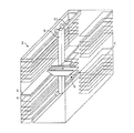
図1は、第1の領域、一般に、一般の棚領域であり(一般に符号2で示される)、通路の両側に内側を向くように備えられ、垂直方向に離隔して設けられた複数の細長い棚4を含むものである。パッケージが薬局で受け取られたとき、それを置くためのコンベヤーベルト5が備えられており、パッケージはそこから取り出され、棚4に配置されるようにすることもできる。このコンベヤーベルトは棚領域2の長さにわたっており、システムが払い出しの注文を満たすことに使用されていないとき、複数のパッケージが一度にシステムに入れられ、その後それらが棚4に配置される。この図では説明を容易にする目的で透明なものとして図示しているが、棚4及び棚後方にある通路の側壁は、通常、パッケージが通り抜けてしまわないように少なくとも十分に閉じられている。
FIG. 1 is a first region, generally a general shelf region (generally indicated by reference numeral 2), provided with a plurality of elongated strips provided inwardly on opposite sides of the passage and spaced vertically. The
通路両側の2つの棚4の間に、ロボットアームアセンブリ6が備えられている。アーム6は垂直な梁8に取り付けられており、摺動台車が、垂直な梁8を上下に移動し、棚4と水平方向に近づいたり離れたりすることができるように備えられている。垂直な梁8は、水平方向に延在する一対のガイドレール10に、並進摺動動作をするように取り付けられる。従って、その構成は、ロボットアーム6がx、y又はz軸方向に自由に動くことを可能にする。さらに、垂直な梁8に取り付けられたアームアセンブリ6は、両側の棚4にアクセスすることができるように、180度の回転動作が可能である。アームアセンブリ6は、このように、棚領域2のどの部分にもアクセスすることができる。図示していないが、当該技術分野では良く知られているように、アームアセンブリ6は一対のかみ合い部を備え、パッケージを移動させるため、かみ合い部は開閉及び上下動し得る。この図ではロボットアーム6は単に図式的に示されているが、実際には、様々な大きさ、形状及び重量のパッケージを、棚4から取り出し、別の場所に移動し、その後排出することができるような、当該技術分野では公知の様々な種類のものであって良い。
A robot arm assembly 6 is provided between the two
図1では、手前側の側壁の一部に一般の棚4が存在しないことを注意されたい。代わりに、本発明では、この領域は頻繁に要求されるパッケージ、即ち「売れ筋の商品」と呼ばれるパッケージ用の第2の領域、即ち、経路領域が備えられる。経路領域の構成要素の一部が、図2に図式的に示されている。
In FIG. 1, it should be noted that the
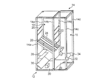
図2を参照すると、経路領域(符号12で示される)は、一般に、前部16及び後部18を画定する外枠14を含むものであり、後部18は、前部16と同じ幅だが、前部16より多少奥行きが深いことが示されている。
Referring to FIG. 2, the path region (shown at 12) generally includes an
枠14は、3組の平行な垂直支柱14a、14b及び14cを含み、各々、枠の後部、中間部、前部にある。一連の水平交差部材20が、後部の垂直支柱14aの間に延在する。同様の水平交差部材22が、中間部の垂直支柱14bの間に延在する。
The
近接して配置された一連の経路構造体24が、後部交差部材20の1つと、中間部交差部材22の1つとの間に延在する。経路構造体24を支持する中間部交差部材22は、対応する後部交差部材20より低い位置にあり、経路構造体24を、例えば、略30°の角度をもって後部から前部に下向きに傾斜させるようにする。説明を容易にするため、図2では、経路24の1つの層だけを示しているが、実際には、異なる高さにて複数の層が平行して備えられて良い。従って、実際には枠の後部18の容積の大部分は、複数の平行な経路24で占められる。
A series of closely spaced
経路24の低い方にあるその前端は、経路領域12の前部16に通じている。前部16は、一般に、広い空間であるが、経路24から落下するパッケージ28の、落下による衝撃を和らげるため、例えば、枠を横断するように引き伸ばされた1つの繊維からなる緩衝プラットフォーム26を下部に備える。緩衝プラットフォーム26は、経路領域の後部に向かって下向きとなるように角度が付けられており、モジュールの後部18の下部において、経路24の層の直ぐ下の下方に備えられたコンベヤーベルトの上に、パッケージ28がゆっくりと落ちるようにする。コンベヤー30は、横方向ならどちらの方向にも動作可能であり、パッケージ28が、モジュール12の左右どちらかに搬送されるようにする。
The lower end of the
1組の赤外線トランスミッタ及びレシーバ32、34が、前部垂直支柱14cの緩衝プラットフォーム26のすぐ上の位置に備えられ、各経路アセンブリ24に対して及び各経路アセンブリ24から、信号を送信及び受信する。その詳細は後述する。コンベヤー30の後方に、傾斜したシュート面36及び複数の追加の棚38がある。その目的は後述する。このように、傾斜した経路24によってできた下部後方の空いた空間を、追加のアウトプット・シュート36及び追加の棚38を取り付けることによって、有効利用していることを理解されたい。
A set of infrared transmitters and
図2の経路モジュール12は分離して示されているが、実際には、上述したような棚領域2内のスペースに配置される。さらに、必要に応じて、経路モジュールが棚領域2に近接して配置されることもできる。
Although the
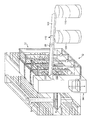
図3、4及び5は、経路アセンブリ24に使用し得る1つの構造の詳細を示している。図3及び4は、各々、経路の前方及び後方から見た図であり、全ての主要な特徴が容易に見られるように短縮遠近法で示している。各経路24は、細長いベース部材40を含み、前部及び後部交差部材20、22に固定されている。ベース部材40は、一対のL字形側壁部材42を支持する。各側壁部材42は、水平に延在する2つのアーム44を有し、その拡大図が図5に示されている。図5で示されるように、アーム44は、歯車の歯48と係合する鋸歯状のエッジ46を備え、ダブルラック及びピニオン駆動方式で、アーム44を反対方向に水平に平行移動させる。これは2つの側壁42を容易に同時に移動させることを可能にし、異なる大きさのパッケージに適合するべく経路の幅を変更するように2つの側壁42が動作し得る。側壁は、オペレータによって手動で調整されるようにすることもできる(即ち、サービスエンジニアを必要としない)、又はロボットアーム6によって移動されるようにすることもできる。別の実施形態(図示なし)では、歯48はサーボモータと置換され、経路が自動的に調整されるようにすることもできる。
3, 4 and 5 show details of one structure that may be used for the
経路24の前部に、ワイヤを立てるようにして配置されたパッケージストッパ50があり、パッケージが経路の前端から滑り落ちないようにする。パッケージストッパ50のすぐ後ろに排出フラップ52があり、フラップの上にあるパッケージを立たせるように起こすことによって、パッケージストッパを押し倒すように動作可能であるため、パッケージを経路の前端から滑り落とせるようにする。
At the front of the
排出装置52のすぐ後ろにパッケージ検出器54があり、パッケージストッパより後方の経路前部にパッケージがあるとき、そのパッケージを検知することができるようにする。同様の検出器56が経路の最前部に備えられ、払い出されたパッケージの通過を検出できるようにする。第3のパッケージ検出器58が経路の後部にあり、経路の後部に新たに進入したパッケージの検出ができるようにする。
There is a
また、利用者が押すと排出装置52を動作させられる手動排出ボタン60及び停電が起きた際に、手動で排出装置52を操作できるようにする機械式の排出レバー62を経路の後部に備えている。手動操作用のノブ60、62は、このように、様々な故障が発生したとき、利用者が、通常、経路の前端からパッケージを排出することを可能にする。図1の参照に戻ると、経路の後方から排出機構を手動で動作可能にすることは、利用者が装置の前方にアクセスする必要がなくなるため有用である。経路モジュール12が設置されると、その後ろには、ロボットアーム6を動作させるために必要な、十分な大きさの空間が存在する。
In addition, a
図3に戻ると、発光ダイオード(LED)64が経路アセンブリ24の前面にあり、装置の故障が発生したとき、所定の注文を満たすため、パッケージを取り出すべき特定の経路であることを利用者に表示するように用いられる。表示用LED64の隣に赤外線エミッタ及びレシーバ66があり、通常の使用時に、排出命令を受信するため及び状態情報を返信するため、経路アセンブリ24を中央コンピュータと通信させる手段である。
Returning to FIG. 3, the light-emitting diode (LED) 64 is in front of the
赤外線エミッタ及びレシーバ68が、経路アセンブリ24の後端に備えられ、例えば、保守整備の間、又は故障が発生したとき、経路24と直接通信することを可能にする。他の実施形態では、ロボットアーム6と所定の通信をするために用いられることもできる。経路の後端面には表示用LED70が備えられ、経路前面のLED64と同様な動作を行い、パッケージが後方から取り出される又は選択されることができるようにする。しかしながら、このLED70は、独立した赤色及び緑色の素子を含み、点灯及び異なる速度での点滅の様々な組合せによって、複数の操作メッセージを利用者に伝達することができ、例えば、取り出されるパッケージを示すメッセージだけではなく、パッケージを入れる必要があること、複数のパッケージを入れる必要があること、在庫がほとんどない又はないこと、入力又は出力エラーがあること、又は経路の在庫が本来あるべき数より多い又は少ないことなどを示すメッセージがあり得る。当然のことながら、特定のメッセージ及び表示形式が、所定の実施形態に適合するように、利用者によって選択されることができることは明らかである。
An infrared emitter and
最後に、経路の後面は経路識別デバイス72を備え、ロボットアーム6からの問い合わせ信号に応じて、経路を識別する信号を送信するように構成される。これはロボットアームが、それが正しい経路であるかどうか確認することを可能にする。
Finally, the rear surface of the route includes a
上述したような実施形態の動作を以下に説明する。動作時には、医薬品パッケージが、適切な投入地点(図示なし)にてシステムに入れられる。ロボットアーム6は、次に各パッケージを1つずつ把持し、適切な識別情報を制御コンピュータに送信し、制御コンピュータは、そのパッケージを配置する場所を教える命令をロボットアーム6に返信する。別の構成では、利用者がパッケージをスキャンするステップを実行し得る(いわゆる半自動モード)。ここで説明する本発明の実施形態では、パッケージは一般の棚4の1つに配置し得る。また、しかしながら、パッケージがいわゆる「売れ筋の商品」の場合、経路モジュール12の経路24の1つに配置されることもできる。ロボットアーム6は、まず経路識別信号を受信するために経路24に問い合わせを行い、それが正しい経路であることを確認する。次に、パッケージを経路24の後部の最上部に配置して、経路に何もない場合、パッケージがパッケージストッパ50まで経路を滑り降りるようにする、又は経路に既に複数のパッケージが存在する場合、パッケージがその複数のパッケージの後方まで経路を滑り降りるようにする。アーム6は、必要に応じて経路24の幅を調整して良く、経路24の側壁42の1つを移動させる。中央コンピュータを介して、又は別の実施態様では赤外線トランスミッタ/レシーバの構成68を用いて、パッケージを追加するための空間があるかどうか(例えば、最後部のパッケージ検出器58が覆われているかどうか)、経路を確認し得る。
The operation of the embodiment as described above will be described below. In operation, the pharmaceutical package is placed into the system at an appropriate loading point (not shown). The robot arm 6 then grips each package one by one and sends the appropriate identification information to the control computer, which returns a command to the robot arm 6 telling where to place the package. In another configuration, the user may perform a step of scanning the package (so-called semi-automatic mode). In the embodiment of the invention described here, the package may be placed on one of the
特定のパッケージの要求を受信すると、この要求は中央コンピュータによって処理され、それが売れ筋の商品ではない場合、棚4から取り出すようにロボットアームに命令を出す、又は売れ筋の商品であった場合、コンピュータは、経路モジュール前方にある赤外線トランスミッタ32(図2)から経路前部のレシーバ66へ赤外線信号を送信することによって、適切な経路24に払い出し指示を送信する。この指示は、パッケージを立たせるように起こすことによって、パッケージがパッケージストッパ50を押し倒すように排出装置52を動作させる。パッケージ38は、経路の端部から緩衝領域26の上に落下し、更にそこからコンベヤー30の上に落下する。複数個のパッケージが頻繁に要求されるパッケージの場合、複数の経路がそれを保管するように用いられることもでき、そのパッケージを複数の経路から同時に払い出すことによって、複数のそのパッケージを要求する注文が、迅速に満たされるようにすることもできる。
Upon receipt of a request for a particular package, this request is processed by the central computer and, if it is not a hot selling item, commands the robot arm to be removed from the
処方箋を満たすために追加のパッケージが要求される場合、これらが経路モジュール12から、又は適切な棚4、38からパッケージを取り出すことができるアーム6を用いて、同時に払い出されることもできるようにし、経路モジュールのアウトプット・シュート36の上にそれらを置くようにする。処方箋の全てのパッケージがコンベヤー30の上に払い出されると、この装置は、それらを搬送シュートなどに搬送するように動作し得るので、各パッケージが搬送地点まで個別に搬送される場合と比較して、注文者はより迅速に全てのパッケージを受け取ることができる。
If additional packages are required to fill the prescription, these can also be dispensed at the same time using the arm 6 that can remove the packages from the
経路モジュール12の一部故障、例えば、主電源の損失が発生した場合、手動の電気式又は機械式排出装置60、62を用いて、人間の手又はロボットアーム6によって医薬品を払い出し続けられるようにすることもできる。さらに、これは医薬品パッケージの取り出しが必要な経路のLEDを点灯することによって著しく容易になる。LEDは電流消費が極めて少ないため、予備バッテリから電源を供給し得る。これによって、オペレータは経路24内のパッケージを自分自身で見る必要がなくなる。
In the event of a partial failure of the
本発明の更なる実施形態が図6に示されている。この実施形態では、4つの別体の経路モジュール74−80が備えられ、全ての経路モジュールは、図2を参照して説明した経路モジュール12とある程度の相違を有する。内側のモジュール76、78に備えられた経路アセンブリは、第1の実施形態の経路アセンブリと同程度の大きさであり、2つの外側のモジュール74、80は、それよりさらに長い経路アセンブリ82を備えている。外側モジュールの長い経路82は容量が大きいことから、売れ筋の商品に特に有用である。
A further embodiment of the invention is shown in FIG. In this embodiment, four separate path modules 74-80 are provided, all of which have some differences from the
第1の実施形態と比較すると、個々のモジュール74−80は、各々コンベヤーシステムを備えておらず、全てのモジュールが、モジュールの前方又は下方に配置された共通のコンベヤーベルト86を使用する。長い外側経路82は、経路の向かい側に配置されている各緩衝プラットフォーム88を用いて、コンベヤー86の上にパッケージを供給する。短い内側経路84用に、同様の緩衝プラットフォームが、これら経路の端部の直ぐ下に備えられているが、これらは説明を容易にするため、図から省略されている。4つのモジュール74−80を含む経路領域全体は、スクリーン90によって保護されており、パッケージが装置から飛び出してしまうことを防止する。
Compared to the first embodiment, the individual modules 74-80 are not each equipped with a conveyor system, and all modules use a
第1の実施形態のように、ロボットアーム用のアウトプット・シュート92が、モジュール74の1つの下部に備えられているが、当然ながら、この実施形態ではコンベヤー86がモジュールの前方にあるため、その長さは第1の実施形態のものよりも長い。シュート92は、図ではモジュールの1つだけに示されているが、実際には、全てのモジュールが同様なシュートを備えている。これは一般の棚からパッケージを取り出して、アウトプット・シュートに配置するまでの移動に必要な、ロボットアームの平均移動距離を短くするため有用である。また、第1の実施形態と同様に、いくつかの追加の棚38が、傾斜した経路82、84の下方のデッドスペースに備えられる。
As in the first embodiment, an output chute 92 for the robot arm is provided at the bottom of one of the
図7は、図1に示す一般の棚4のない部分に、図6の経路領域が組込まれているところを示している。パッケージ28がコンベヤー86で搬送されることに関して、この実施形態の動作は、第1の実施形態と全く同一であるため、ここではその説明を繰り返して行わない。また、コンベヤー86は、好ましくは、バッファとして機能することができるものであり、1つの注文で要求される全てのパッケージを一緒に集める。従来、パッケージは次のパッケージの移動が開始される前に、最終搬送地点まで搬送される必要があると考えられていたため、各パッケージは個別にアウトプットされていた。その場合と比較して、これは全部のパッケージがまとめて利用者にアウトプットされるため、アウトプット速度を著しく向上させる。
FIG. 7 shows that the route region of FIG. 6 is incorporated in a portion without the
リフトシステムが新たに図7で示されている(一般に符号94で示される)。リフトシステムは、リフティングプラットフォーム96を広く含むものであり、リフトシャフト98内部で、垂直に、シャフトのベースから2つの上方の開口100、102まで駆動される。小型のコンベヤーベルト104が、リフティングプラットフォーム96のベースを形成している。プラットフォームは、側壁を有していても良く、有していなくても良い。そして、必要に応じて、経路領域のコンベヤー86と対向する側面及び開口100、102と対向する側面の両方に、各々ドアまたはゲートを備えても良い。図に示されているように、動作時には、リフティングプラットフォーム96のコンベヤー104が最も低い位置にあるとき、固定的な搬送手段86の上にあるパッケージが、コンベヤー104の上に搬送され、次にベースコンベヤー104が開口100、102の1つと同じ高さになるまで、リフティングプラットフォームが上昇させられる。ベースコンベヤー104の上のパッケージは、次に、パッケージを前方に移動して、プラットフォーム96から出ていくようにコンベヤーを動作させることによって、容易に、各開口100、102と結合した搬送シュート又はスライドの上に排出されるようにすることもできる。
A new lift system is shown in FIG. 7 (generally indicated at 94). The lift system broadly includes a
本発明の更なる実施形態が図8に示されている。実際のところ、この実施形態は、図1に示す一般の棚領域に、図2に示す経路モジュール12を単純に3個組み合わせたものである。リフトモジュール94は、図7を参照して説明したものと同一であり、経路領域の一方の端部において示されている。また、この実施形態では、搬送コンベヤー106が明示されており、2つのリフトの開口のうち上側の開口102と結合している。搬送コンベヤー106は、2つのらせん状(スパイラル)の最終搬送シュート108、110にパッケージを供給する役割を果たし、コンベヤー106の通路を横断するように備えられたスイング式の切替バー112は、特定のパッケージ38を、どちらの搬送シュート108、110に落下させるかを選択可能にするものである。
A further embodiment of the invention is shown in FIG. Actually, in this embodiment, the general shelf area shown in FIG. 1 is simply combined with three
リフトモジュールの複数のアウトプット100、102は、しかし、搬送経路の選択をする必要がないため、下流側のコンベヤーシステムの単純化を可能にする。これは制御ソフトウェアがより単純になるようにし、全体のアウトプット速度を速くすることも可能にする。
The
図9−13は、リフトモジュールの様々な異なる構造を示している。まず図9を参照すると、本発明に使用し得るリフト構造の図式的な断面図が示されている。この構造では、リフティングプラットフォーム114は、シャフト116内部で垂直方向に動作するように吊るされている。シャフト116は、コンベヤーの所定領域に、下部入力用開口118を備え、上方には、パッケージをアウトプットするための3つの開口122、124、126を備えている。3つの開口は、当然のことながら、単純に実施例としてあげただけであり、必要に応じて様々な数の開口が備えられて良い。リフティングプラットフォーム114は、各モータ132、134によって駆動される、2つの独立して駆動するロープ又はベルト128、130で吊るされている。ロープ128の一方は、プラットフォーム114に直接結合され、ロープ130の一方は、壁部材136に結合されている。壁部材136は、ちょうつがいで動作可能なようにプラットフォーム114に取り付けられている。
Figures 9-13 show various different configurations of the lift module. Referring first to FIG. 9, there is shown a schematic cross-sectional view of a lift structure that can be used with the present invention. In this configuration, the
使用時には、パッケージ38はコンベヤー120によって届けられ、入力用開口118を介して搬送され、そこから、リフティングプラットフォーム114及び側壁136によって形成される楔形のバケツに落下する。所定の注文の全てのパッケージ28が集まると、2つのモータ132、134がプラットフォーム114を上昇させるべく作動される。プラットフォームが所望の出口用開口、例えば、図9で示される3つの開口のうちの2番目の開口124に到達すると、左手側のモータ132は停止されるが、右手側のモータ134は継続して作動し、対応するロープ130の長さを更に短くする。それによって、プラットフォーム114は、パッケージ38が、出口用開口124を介して、プラットフォームからコンベヤー又はシュートの上に滑り落ちるまで傾けられる。このように、リフト手段がバッファとして機能して良いことを理解されたい。
In use, the
図10で示すリフト構造は、プーリーが最上部に備えられたプーリー付シャフト136、138の下部にモータ132、134が配置されていることを除き、図9のリフト構造と類似している。この構造は、保守整備の際にモータ132、134に容易にアクセスすることができるようになる点で有用であり得る。また、プラットフォームと、アウトプット用開口との間が近接した状態を維持し得る。
The lift structure shown in FIG. 10 is similar to the lift structure shown in FIG. 9 except that
更なるリフト構造が、図11及び図12に示されている。この構造では、パッケージを収容するように、コンベヤーベルトのベース及び3つの傾斜した側壁142からなるリフト用「バケツ」が、傾斜したコンベヤーベルト140に形成されている。図11の図の下部では、パッケージ28を、棚領域のコンベヤーからバケツに受け取るような構成が示されている。バケツは、次に2つの出口用開口146、148のどちらか1つの高さまで上昇されて良く、コンベヤー140が、パッケージをシュート内に又は次のコンベヤーの上に排出するように動作する。
A further lift structure is shown in FIGS. In this structure, a lift “bucket” consisting of a base of the conveyor belt and three
更なるリフト構造が図13に示されている。この構造では、リフトボックス150は傾斜した床152を備えるものであり、モータ156により作動されるローラ式シャッタ154によって前方が閉じられる。図13の図の下部で示されるように、シャッタ154が下ろされると、ボックス150の最上部に開口ができ、パッケージがその中に入るようにする。リフトボックス150は、次に上方の高い位置まで上昇され、シャッタ用モータ156を作動させてシャッタを上げることによって、リフトボックス150に収容されたパッケージが、傾斜した床152を滑り落ちるようにする。
A further lift structure is shown in FIG. In this structure, the lift box 150 includes an
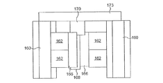
図14−19を参照すると、本発明で使用し得る様々なモジュールの様々なレイアウトが示されている。図14は、本発明で使用し得るレイアウトの1つを示している。このレイアウトでは、ロボットアーム(図示なし)が備えられる第1の一般の棚領域160が、薬局の幅にわたって延在している。一般の棚領域の一方の側面には経路領域が備えられ、経路領域は5つの経路モジュール162、164を含んでいる。モジュールのうちの2つは、通常の経路モジュール162であり、他の3つは奥行きの深いモジュール164である。奥行きの深いモジュール及び奥行きの浅いモジュールの実施形態は、図6及び図7を参照して説明した実施形態のようなものであり得る。
14-19, various layouts of various modules that can be used in the present invention are shown. FIG. 14 shows one of the layouts that can be used in the present invention. In this layout, a first
奥行きの深い各経路モジュール164の前方にはパッケージ落下領域166が備えられ、パッケージが着地する際の衝撃を和らげ、パッケージがコンベヤー168の上にのるように、パッケージを後方に向かって移動させるような役割を果たす。コンベヤー168は、5つのモジュール全てに共通のものであり、奥行きの深いモジュール164の下方、かつ奥行きの浅いモジュール162の前方に備えられている。コンベヤー168の両端には、各々2つの出口を有するリフトモジュール170が備えられている。この構成は、4つのオペレータステーション172のうちのいずれか1つが、適切なリフトモジュール170及びそのリフトの適切な出口に対して、特定の処方箋を指示することによって、装置よりパッケージが供給されるようにすることができることを意味する。
A
本発明に使用し得る別のレイアウトが図15に示されている。この構成では、コンベヤー168は、3つの経路モジュール162、162´の下方に備えられており、パッケージ落下領域166がモジュールの前方に備えられている。モジュール162、162´は、従って、図2を参照して説明したモジュールと類似したものである。しかしながら、この構成では、一般の棚160の領域には経路モジュール162が2つだけ備えられ、ロボットアームはこれらを満たすようにアクセスすることができることに注意されたい。第3のモジュール162´は、手動で満たされるように、後方から直接アクセスすることができるものである。これはシステムにパッケージを入れる全体入力速度を向上し得る。
Another layout that may be used with the present invention is shown in FIG. In this configuration, the
図16は本発明に使用し得る別のレイアウトを示す。この構成では、2つの手動で満たされる経路モジュール162´が、一般の棚領域160のロボットアームで満たされる2つのモジュール162に対向して配置されている。対向する一対のモジュールは、各々パッケージ落下領域166を有し、パッケージを順に共通のコンベヤー168に移動させ、コンベヤー168は、それらを順にリフトモジュール170に入れる。この構成において空間を節約するため、全てのモジュール162及び162´用に、1つの落下領域を備え、上述したような実施形態のように、左端のモジュール162の下方にコンベヤーを備えるように変更することもできる。
FIG. 16 shows another layout that may be used with the present invention. In this configuration, two manually filled
図17は、図16の構成と類似したタンデムレイアウトを示しているが、第2の棚領域160及びそれに備えられているするロボットアームが、右端の経路モジュール162を満たすことを特徴とする。この実施形態は、2つの一般の棚領域160の間に追加のコンベヤー173を備え、在庫をその両者の間で移動させるようにする、又は棚領域160(経路モジュール162と対向している)から取出されたパッケージがリフト170の上に置かれるようにする。これは、例えば、パッケージがシステムのどこに保管されていたとしても、処方箋を満たすために必要な全てのパッケージをまとめて集めるように、リフト170をバッファとして機能させることから有用である。
FIG. 17 shows a tandem layout similar to the configuration of FIG. 16, but the
図18は、ロボットアームが備えられている2つの別体の棚領域160が、各々2つの経路モジュール162にパッケージを供給するような構成を示しているが、上述したようなレイアウトのように、処方薬用のバッファとして機能し得る共通のリフト170が備えられている。また、この実施形態は、モジュール162の一端にコンベヤーを備えるように変更することもでき、その場合、その下部に本発明の好適な実施形態のモジュールを配置し得る。
FIG. 18 shows a configuration in which two
最後に、図19は装置の保管部の構成を示しており、それは実際の薬局受付より上の階の床面に構成され、そこから医薬品パッケージの支給を要求される。この実施形態では、ロボットアームが備えられている棚領域160は、上述したような実施形態のように、2つの経路モジュール162にパッケージを供給する。しかしながら、上述したような実施形態とは異なり、コンベヤー168は、その両端において2つの孔174の1つにパッケージを供給する。2つの孔は床を貫通し、下の階の天井と同じくらいの高さに備えられている各コンベヤー176の上に通じている。各コンベヤーは、3つのらせん状(スパイラル)のシュート178にパッケージを供給し、シュートは、パッケージを取出せるような高さまで、パッケージを下方に下ろす。リフトモジュールが必要ではないため、この構成はコストを節約することができる。
Finally, FIG. 19 shows the configuration of the storage unit of the apparatus, which is configured on the floor of the floor above the actual pharmacy reception, from which the supply of the pharmaceutical package is required. In this embodiment, the
スイング式の切替バー180が、コンベヤー176の上に備えられており、目的のシュートが正しく選択されるようにする。よって、この実施形態では6人のオペレータが、各自それぞれの場所でパッケージを受け取ることができる。
A swinging
図20は、本発明に基づく経路200の更なる実施形態を示している。この実施形態では、経路200は、図3乃至5を参照して上述したような主要部材202を広く含み、そして付属部材204も含むものである。主要部材及び付属部材202、204は、1組のレール206に取り付けられており、レールに沿って手動で摺動可能であることから、互いに近づけたり、離したりすることによって経路の幅を調整し得る。この調整量は、LED70によって表示することもでき、LEDの点滅を適切に組み合わせることによって表示し得る(例えば、幅が広い場合は赤色、幅が狭い場合は緑色を用いる)。パッケージ検出器54−58、排出ボタン60、62、赤外線検出器及びレシーバ68、表示用LED70及び経路識別装置72は、上述したものと同じものである。
FIG. 20 shows a further embodiment of a
しかし、この実施形態は、異なる排出機構208が組込まれているため、その詳細を図21a及び21bを参照して説明する。排出機構208は、経路202に対してピボット可能に取り付けられたフード形状をした部材210を含むものである。ピボット部材210は、ベースプレート212及び直立した壁214を備えている。シャフト216は、ベースプレート212から下方に延在し、その下端がピボットの支点として用いられる。シャフト216は、ピボットの支点より上方に形状記憶ワイヤ218の一端が取り付けられている。ワイヤ218の反対側の一端は、経路本体202に固定されている。また、シャフト216はピボットの支点より上方に保持スプリング220が取り付けられている。
However, since this embodiment incorporates a
図21aは、通常の待機位置を示しており、ベースプレートは、実質的に経路本体202の上側の面と同一平面上にあり、パッケージ222aは、端壁214に支えられるようにしてベースプレートの上に受け止められている。電流が形状記憶ワイヤ218を通過すると、その電気抵抗でワイヤは加熱され、次にワイヤはその「加熱した」元の形状に戻り、放熱状態の形状と比較して直線状に長く伸びた形状となる。このようにワイヤが伸びると、その伸びがピボット部材のシャフト216に伝達され、ピボット部材を前方に傾かせるようにする。これは最前部のパッケージ222aを傾斜した経路の端部から滑り落とし、それが排出されるようにする。しかしながら、同時に、ベースプレート212の後端が上方に上がるため、後ろのパッケージ222bはピボット部材210の上に移動することができず、排出もされない。
FIG. 21 a shows a normal standby position, where the base plate is substantially flush with the upper surface of the
ワイヤ218への電流の供給を止めると、ワイヤは再び収縮し、スプリング220の付勢によって、ピボット部材210はその待機位置に戻る。これは次のパッケージ222bがピボット部材210の上に移動して受け止められることによって、次の排出ができるような状態にする。従って、パッケージを、簡単に、確実に、1つずつ排出することができるようになったことを理解されたい。
When the supply of current to the
上述したような実施形態は単なる実施例であり、本発明の範囲内で様々な変形が可能であることは、当業者には明らかであろう。 It will be apparent to those skilled in the art that the above-described embodiments are merely examples, and various modifications can be made within the scope of the present invention.
Claims (53)
保管及び把持デバイスでアクセス可能な複数の棚を含む第1の領域と、
各々が独立した排出手段を有する、各々が複数のパッケージを受け取るための複数の経路を含む第2の領域とを備え、
前記保管及び把持デバイスが、前記第2の領域の前記経路を満たすように構成され、
前記装置が、前記第2の領域と関連する、前記第2の領域から排出されたパッケージを移動させるための搬送手段をさらに備えることを特徴とする装置。 An apparatus for storing and dispensing a plurality of packages,
A first region including a plurality of shelves accessible with a storage and gripping device;
A second region, each having an independent discharge means, each including a plurality of paths for receiving a plurality of packages;
The storage and gripping device is configured to fill the path of the second region;
The apparatus further comprising transport means for moving a package discharged from the second area associated with the second area.
その後、新たなパッケージが前記経路の最前部に受け取られるように、残りのパッケージが前記経路を滑り降りるように構成されることを特徴とする請求項1乃至18のいずれかに記載の装置。 The discharging means provided in each path causes the package received at the forefront of the path to be dropped or discharged from the front of the path while discharging other packages received in the path. To avoid being
19. An apparatus according to any preceding claim, wherein the remaining packages are configured to slide down the path so that new packages are then received at the forefront of the path.
前記ピボット部材は、前記第2の位置において、さらに追加のパッケージを受け取るのを阻止するように構成されることを特徴とする請求項1乃至19のいずれかに記載の装置。 The ejecting means comprises a pivot member configured to pivot from a first position for receiving a package to a second position for ejecting the package;
20. An apparatus according to any preceding claim, wherein the pivot member is configured to prevent further packages from being received in the second position.
複数の別体の保管領域と、
前記保管領域にパッケージを入れるための充填手段とを備え、
前記装置が、前記充填手段と、前記各保管領域との間で情報を伝達するための手段をさらに備えることを特徴とする装置。 An apparatus for storing and dispensing a plurality of packages,
Multiple separate storage areas;
Filling means for placing a package in the storage area;
The apparatus further comprising means for communicating information between the filling means and each storage area.
複数のパッケージの物理的な位置を記録するデータベースと、
パッケージの注文を処理するための中央モジュールとを備え、
前記コンピュータシステムは、各々が、前記注文処理用モジュールと相互作用するように構成された複数のユーザインタフェースモジュールを備え、注文のアップロード及び前記注文の状態の監視が可能となるようにすることを特徴とするコンピュータシステム。 A computer system for operating the apparatus according to any one of claims 1 to 49, comprising:
A database that records the physical location of multiple packages;
A central module for processing package orders,
The computer system comprises a plurality of user interface modules, each configured to interact with the order processing module, to enable order upload and order status monitoring. Computer system.
複数のパッケージの物理的な位置を記録するデータベースと、
パッケージの注文を処理するための中央モジュールとを備え、
前記コンピュータシステムは、各々が、前記注文処理用モジュールと相互作用するように構成された複数のユーザインタフェースモジュールを備え、注文のアップロード及び前記注文の状態の監視が可能となるようにすることを特徴とするコンピュータシステム。 A computer system for operating an automated pharmacy,
A database that records the physical location of multiple packages;
A central module for processing package orders,
The computer system comprises a plurality of user interface modules, each configured to interact with the order processing module, to enable order upload and order status monitoring. Computer system.
前記排出手段が、パッケージを受け取る第1の位置から、前記パッケージを排出する第2の位置までピボットするように構成されたピボット部材を備え、
前記ピボット部材は、前記第2の位置で追加のパッケージを受け取るのを阻止するように構成されることを特徴とする経路及び排出手段。 A path for receiving a plurality of packages and a discharge means for discharging the packages one by one from the path,
The ejecting means comprises a pivot member configured to pivot from a first position for receiving a package to a second position for ejecting the package;
A path and discharge means, wherein the pivot member is configured to prevent receiving additional packages at the second position.
Applications Claiming Priority (3)
| Application Number | Priority Date | Filing Date | Title |
|---|---|---|---|
| GB0425142A GB0425142D0 (en) | 2004-11-15 | 2004-11-15 | Apparatus for storing and dispensing packages |
| GB0505395A GB0505395D0 (en) | 2005-03-16 | 2005-03-16 | Apparatus for storing and dispensing packages |
| PCT/GB2005/004384 WO2006051329A2 (en) | 2004-11-15 | 2005-11-15 | Apparatus for storing and for independent dispensing of a plurality of packages |
Publications (2)
| Publication Number | Publication Date |
|---|---|
| JP2008519743A true JP2008519743A (en) | 2008-06-12 |
| JP2008519743A5 JP2008519743A5 (en) | 2008-11-13 |
Family
ID=35501186
Family Applications (1)
| Application Number | Title | Priority Date | Filing Date |
|---|---|---|---|
| JP2007540719A Pending JP2008519743A (en) | 2004-11-15 | 2005-11-15 | Equipment for storing and dispensing packages |
Country Status (8)
| Country | Link |
|---|---|
| US (1) | US20100089941A1 (en) |
| EP (2) | EP1836111B1 (en) |
| JP (1) | JP2008519743A (en) |
| AT (1) | ATE540883T1 (en) |
| AU (1) | AU2005303532A1 (en) |
| CA (1) | CA2587578A1 (en) |
| DE (1) | DE05803577T1 (en) |
| WO (1) | WO2006051329A2 (en) |
Cited By (3)
| Publication number | Priority date | Publication date | Assignee | Title |
|---|---|---|---|---|
| CN103158966A (en) * | 2011-12-16 | 2013-06-19 | 路海英 | Medicine storing device of automated pharmacy for traditional Chinese medicine decoction pieces in small packs |
| KR20170102466A (en) * | 2015-01-09 | 2017-09-11 | 벡톤 디킨슨 로와 저머니 게임베하 | Commissioning Device and Process for Outputting Piece Goods Using the Commissioning Device |
| JP2018529599A (en) * | 2015-09-08 | 2018-10-11 | ベクトン・ディッキンソン・ロワ・ジャーマニー・ゲーエムベーハー | Method for storing a plurality of identical single items in a picking device |
Families Citing this family (16)
| Publication number | Priority date | Publication date | Assignee | Title |
|---|---|---|---|---|
| DE202007013479U1 (en) * | 2007-09-25 | 2008-03-27 | Kht Kommissionier- Und Handhabungstechnik Gmbh | Device for storing and retrieving piece goods and in particular medicament packs |
| DE102010047872A1 (en) * | 2009-10-26 | 2011-05-19 | Westfalia Intralogistic Gmbh | bearing arrangement |
| US9390576B2 (en) * | 2012-07-31 | 2016-07-12 | Flextronics, AP LLC | Robotic package lifting assembly and method |
| WO2014191106A1 (en) * | 2013-05-31 | 2014-12-04 | Wrh Walter Reist Holding Ag | Bearing device, bearing system and method for operating a bearing system |
| AT13986U1 (en) * | 2013-09-18 | 2015-02-15 | Knapp Ag | Picking system with buffer shells containing shelf units for picking on a central belt |
| US20150094840A1 (en) * | 2013-09-30 | 2015-04-02 | Shutterfly, Inc. | Order consolidation stations having intelligent light indicators |
| CN103738633B (en) * | 2013-12-30 | 2016-02-03 | 苏州艾隆科技股份有限公司 | A kind of intelligent drugstore system of automatic tonic |
| CN103738636B (en) * | 2013-12-30 | 2016-02-03 | 苏州艾隆科技股份有限公司 | A kind of intelligent medicine-feeding method |
| US9567119B2 (en) | 2014-07-23 | 2017-02-14 | Express Scripts, Inc. | Systems and methods for manual countables |
| CN104443998B (en) * | 2014-11-21 | 2017-01-18 | 苏州艾隆科技股份有限公司 | Modular medicine discharging tank |
| CN104443997B (en) * | 2014-11-21 | 2017-04-05 | 苏州艾隆科技股份有限公司 | For the spiral straight hair delivery system and drug method of Intelligent Pharmacy |
| US9975698B2 (en) | 2015-01-09 | 2018-05-22 | Carefusion Germany 326 Gmbh | Commissioning device for piece goods |
| DE102015118832B3 (en) | 2015-11-03 | 2017-01-26 | SSI Schäfer Noell GmbH Lager- und Systemtechnik | Storage and picking system and method for storing piece goods in a picking machine |
| US10521562B2 (en) * | 2016-06-02 | 2019-12-31 | Becton Dickinson Rowa Germany Gmbh | Automatic picking machine for filling a transport container |
| US11389012B2 (en) * | 2017-07-13 | 2022-07-19 | Jorge Benitez Torres | Automated multi-dispenser and multi-replenisher of products, and method for product unloading |
| WO2019186345A2 (en) * | 2018-03-27 | 2019-10-03 | Dematic Corp. | Layer board flow mechanism for replenishment of a picking system |
Citations (12)
| Publication number | Priority date | Publication date | Assignee | Title |
|---|---|---|---|---|
| JPS53147381A (en) * | 1977-05-26 | 1978-12-22 | Ishikawajima Harima Heavy Ind Co Ltd | Automatic housing device |
| JPS5511482A (en) * | 1978-07-12 | 1980-01-26 | Toshiba Corp | Take-out method for stored goods |
| JPS58193824A (en) * | 1982-04-23 | 1983-11-11 | ゲプハルト・フエルダ−テヒニク・ゲゼルシヤフト・ミツト・ベシユレンクテル・ハフツング | Selector for single article |
| JPS5936001A (en) * | 1982-08-20 | 1984-02-28 | Tsubakimoto Chain Co | Automatic warehousing and delivery device |
| JPH0260648A (en) * | 1988-08-26 | 1990-03-01 | Central Unie:Kk | Automatic injecting drug paying out device |
| JPH04125207A (en) * | 1990-09-17 | 1992-04-24 | Daifuku Co Ltd | Picking facility |
| JPH05208705A (en) * | 1992-01-31 | 1993-08-20 | Wing Lab:Kk | Multi-storied warehouse |
| JPH05221511A (en) * | 1992-02-13 | 1993-08-31 | Kao Corp | Article handling device |
| JPH05301601A (en) * | 1992-04-24 | 1993-11-16 | Nippon Shiyuutaa:Kk | Carrier equipment in building and conveyance method by carrier equipment |
| JPH06278825A (en) * | 1993-11-12 | 1994-10-04 | Tokyo Shokai:Kk | Injection medicine preparing machine |
| JP2003081429A (en) * | 2001-09-14 | 2003-03-19 | Matsushita Electric Ind Co Ltd | Device for automatically putting out injection drug |
| JP2004231303A (en) * | 2003-01-28 | 2004-08-19 | Daifuku Co Ltd | Article work handling method |
Family Cites Families (17)
| Publication number | Priority date | Publication date | Assignee | Title |
|---|---|---|---|---|
| US3132732A (en) * | 1962-02-27 | 1964-05-12 | Come Letourneau | Coin operated vending machine |
| US3687337A (en) * | 1969-10-15 | 1972-08-29 | Antonio Burlando | Automatic vending machine with horizontal arrangement |
| US3737071A (en) * | 1972-03-17 | 1973-06-05 | Vendo Co | Product dispensing apparatus |
| US5226619A (en) * | 1991-10-15 | 1993-07-13 | Alger Robert E | Actuator mechanism |
| US5271703A (en) * | 1992-05-08 | 1993-12-21 | Si Handling System, Inc. | Automatic order selection system capable of responding to simultaneous order requests |
| US6272394B1 (en) * | 1993-07-21 | 2001-08-07 | Omnicell.Com | Methods and apparatus for dispensing items |
| JPH09223269A (en) * | 1995-12-14 | 1997-08-26 | Silk Hosei Kojo:Kk | Automatic vending device |
| NL1003596C2 (en) * | 1996-07-15 | 1997-05-27 | Cons Health Entrepreneurs Bv | Vending machine dispenser. |
| US5831820A (en) * | 1996-12-30 | 1998-11-03 | Huang; James | Peripheral docking module using a shape memory alloy actuator wire |
| US6061607A (en) * | 1997-07-18 | 2000-05-09 | St. Onge Company | Order pick system |
| US6011999A (en) * | 1997-12-05 | 2000-01-04 | Omnicell Technologies, Inc. | Apparatus for controlled dispensing of pharmaceutical and medical supplies |
| DE19815883A1 (en) * | 1998-04-08 | 1999-10-14 | Knapp Logistik Automation | Order picking system |
| DE19857282A1 (en) * | 1998-12-13 | 2000-06-29 | Stefan Stirnberg | Fully automatic medication package supply involves use of jointed robot with 5 or more degrees of freedom and/or acquisition of identification information, and/or single or collective stores |
| FR2807410B1 (en) * | 2000-04-10 | 2002-06-07 | Pharmax | DEVICE AND INSTALLATION FOR DELIVERY OF OBJECTS STORED ONLINE |
| DE10136090A1 (en) | 2001-07-26 | 2003-02-27 | Dirk Rolf Beils | Process and device for computer-controlled storage and retrieval of small-scale products |
| DE20204573U1 (en) * | 2002-03-21 | 2003-08-28 | Willach Gmbh Geb | dispenser |
| FR2837479B1 (en) * | 2002-03-21 | 2004-07-09 | Connier Realisations Automates | AUTOMATED STORAGE, DELIVERY AND TRANSPORT OF PRODUCTS |
-
2005
- 2005-11-15 EP EP05803577A patent/EP1836111B1/en not_active Revoked
- 2005-11-15 AU AU2005303532A patent/AU2005303532A1/en not_active Abandoned
- 2005-11-15 JP JP2007540719A patent/JP2008519743A/en active Pending
- 2005-11-15 WO PCT/GB2005/004384 patent/WO2006051329A2/en active Application Filing
- 2005-11-15 US US11/719,370 patent/US20100089941A1/en not_active Abandoned
- 2005-11-15 CA CA002587578A patent/CA2587578A1/en not_active Abandoned
- 2005-11-15 DE DE05803577T patent/DE05803577T1/en active Pending
- 2005-11-15 EP EP11164853A patent/EP2402267A3/en not_active Withdrawn
- 2005-11-15 AT AT05803577T patent/ATE540883T1/en active
Patent Citations (12)
| Publication number | Priority date | Publication date | Assignee | Title |
|---|---|---|---|---|
| JPS53147381A (en) * | 1977-05-26 | 1978-12-22 | Ishikawajima Harima Heavy Ind Co Ltd | Automatic housing device |
| JPS5511482A (en) * | 1978-07-12 | 1980-01-26 | Toshiba Corp | Take-out method for stored goods |
| JPS58193824A (en) * | 1982-04-23 | 1983-11-11 | ゲプハルト・フエルダ−テヒニク・ゲゼルシヤフト・ミツト・ベシユレンクテル・ハフツング | Selector for single article |
| JPS5936001A (en) * | 1982-08-20 | 1984-02-28 | Tsubakimoto Chain Co | Automatic warehousing and delivery device |
| JPH0260648A (en) * | 1988-08-26 | 1990-03-01 | Central Unie:Kk | Automatic injecting drug paying out device |
| JPH04125207A (en) * | 1990-09-17 | 1992-04-24 | Daifuku Co Ltd | Picking facility |
| JPH05208705A (en) * | 1992-01-31 | 1993-08-20 | Wing Lab:Kk | Multi-storied warehouse |
| JPH05221511A (en) * | 1992-02-13 | 1993-08-31 | Kao Corp | Article handling device |
| JPH05301601A (en) * | 1992-04-24 | 1993-11-16 | Nippon Shiyuutaa:Kk | Carrier equipment in building and conveyance method by carrier equipment |
| JPH06278825A (en) * | 1993-11-12 | 1994-10-04 | Tokyo Shokai:Kk | Injection medicine preparing machine |
| JP2003081429A (en) * | 2001-09-14 | 2003-03-19 | Matsushita Electric Ind Co Ltd | Device for automatically putting out injection drug |
| JP2004231303A (en) * | 2003-01-28 | 2004-08-19 | Daifuku Co Ltd | Article work handling method |
Cited By (7)
| Publication number | Priority date | Publication date | Assignee | Title |
|---|---|---|---|---|
| CN103158966A (en) * | 2011-12-16 | 2013-06-19 | 路海英 | Medicine storing device of automated pharmacy for traditional Chinese medicine decoction pieces in small packs |
| KR20170102466A (en) * | 2015-01-09 | 2017-09-11 | 벡톤 디킨슨 로와 저머니 게임베하 | Commissioning Device and Process for Outputting Piece Goods Using the Commissioning Device |
| JP2018501168A (en) * | 2015-01-09 | 2018-01-18 | ベクトン・ディッキンソン・ロワ・ジャーマニー・ゲーエムベーハー | Intermediary device and process for outputting unit goods using the intermediary device |
| JP2021011388A (en) * | 2015-01-09 | 2021-02-04 | ベクトン・ディッキンソン・ロワ・ジャーマニー・ゲーエムベーハー | Handling device and process of outputting unit commodity using handling device |
| KR102436228B1 (en) * | 2015-01-09 | 2022-08-25 | 벡톤 디킨슨 로와 저머니 게임베하 | Commissioning Device and Process for Outputting Piece Goods Using the Commissioning Device |
| JP7143383B2 (en) | 2015-01-09 | 2022-09-28 | ベクトン・ディッキンソン・ロワ・ジャーマニー・ゲーエムベーハー | A transfer device and a process for outputting unit products using the transfer device |
| JP2018529599A (en) * | 2015-09-08 | 2018-10-11 | ベクトン・ディッキンソン・ロワ・ジャーマニー・ゲーエムベーハー | Method for storing a plurality of identical single items in a picking device |
Also Published As
| Publication number | Publication date |
|---|---|
| US20100089941A1 (en) | 2010-04-15 |
| WO2006051329A2 (en) | 2006-05-18 |
| EP1836111A2 (en) | 2007-09-26 |
| AU2005303532A1 (en) | 2006-05-18 |
| DE05803577T1 (en) | 2010-09-23 |
| EP2402267A3 (en) | 2012-05-02 |
| EP2402267A2 (en) | 2012-01-04 |
| EP1836111B1 (en) | 2012-01-11 |
| ATE540883T1 (en) | 2012-01-15 |
| CA2587578A1 (en) | 2006-05-18 |
| WO2006051329A3 (en) | 2006-08-03 |
Similar Documents
| Publication | Publication Date | Title |
|---|---|---|
| JP2008519743A (en) | Equipment for storing and dispensing packages | |
| KR102439196B1 (en) | Systems and methods for picking items | |
| US5273392A (en) | Automated work center and method | |
| US5222855A (en) | Automated work center | |
| CN102173332B (en) | Vibration-based ejection cassette, drug dispensing apparatus, ptp dispensing apparatus, pharmaceutical product storage apparatus and ptp dispensing system | |
| US5161929A (en) | Automated work center | |
| CN101102946A (en) | Apparatus for storing and for independent dispensing of a plurality of packages | |
| US20030222091A1 (en) | Authomated pill-dispensing apparatus | |
| JP5774282B2 (en) | Product carrying device | |
| CA2249695A1 (en) | Tablet packing apparatus | |
| CN110751782A (en) | Automatic container | |
| CN111526760B (en) | Storage device, commodity delivery system, and stock abnormality detection method | |
| JP6973357B2 (en) | Picking system | |
| JP6881446B2 (en) | Transport system and drug dispensing system | |
| EP0406268B1 (en) | Automated work center | |
| JPWO2019163683A1 (en) | Chemicals dispenser | |
| JP3791260B2 (en) | Merchandise take-out and conveying device in vending machine and control method thereof | |
| JP2841266B2 (en) | Article handling equipment | |
| US20240005270A1 (en) | Increasing the capacity of different types of products and matching stock with forecasted sales volumes per product type in automatic vending machines | |
| JP4352318B2 (en) | Goods storage facility | |
| JPH10329910A (en) | Discharge and carrying out device for container accommodated in machine body and their discharge and carrying out method | |
| JP2896010B2 (en) | vending machine | |
| JPH0952620A (en) | Article selecting device | |
| JPH08127423A (en) | Transferring method of article and device thereof | |
| JPH08133421A (en) | Injection drug take out device |
Legal Events
| Date | Code | Title | Description |
|---|---|---|---|
| A521 | Request for written amendment filed |
Free format text: JAPANESE INTERMEDIATE CODE: A523 Effective date: 20080919 |
|
| A621 | Written request for application examination |
Free format text: JAPANESE INTERMEDIATE CODE: A621 Effective date: 20080919 |
|
| A977 | Report on retrieval |
Free format text: JAPANESE INTERMEDIATE CODE: A971007 Effective date: 20111021 |
|
| A131 | Notification of reasons for refusal |
Free format text: JAPANESE INTERMEDIATE CODE: A131 Effective date: 20111129 |
|
| A02 | Decision of refusal |
Free format text: JAPANESE INTERMEDIATE CODE: A02 Effective date: 20120424 |