JP2008517677A - Medical device delivery catheter - Google Patents
Medical device delivery catheter Download PDFInfo
- Publication number
- JP2008517677A JP2008517677A JP2007538197A JP2007538197A JP2008517677A JP 2008517677 A JP2008517677 A JP 2008517677A JP 2007538197 A JP2007538197 A JP 2007538197A JP 2007538197 A JP2007538197 A JP 2007538197A JP 2008517677 A JP2008517677 A JP 2008517677A
- Authority
- JP
- Japan
- Prior art keywords
- pod
- medical device
- distal
- actuator
- open
- Prior art date
- Legal status (The legal status is an assumption and is not a legal conclusion. Google has not performed a legal analysis and makes no representation as to the accuracy of the status listed.)
- Pending
Links
Images


Classifications
-
- A—HUMAN NECESSITIES
- A61—MEDICAL OR VETERINARY SCIENCE; HYGIENE
- A61F—FILTERS IMPLANTABLE INTO BLOOD VESSELS; PROSTHESES; DEVICES PROVIDING PATENCY TO, OR PREVENTING COLLAPSING OF, TUBULAR STRUCTURES OF THE BODY, e.g. STENTS; ORTHOPAEDIC, NURSING OR CONTRACEPTIVE DEVICES; FOMENTATION; TREATMENT OR PROTECTION OF EYES OR EARS; BANDAGES, DRESSINGS OR ABSORBENT PADS; FIRST-AID KITS
- A61F2/00—Filters implantable into blood vessels; Prostheses, i.e. artificial substitutes or replacements for parts of the body; Appliances for connecting them with the body; Devices providing patency to, or preventing collapsing of, tubular structures of the body, e.g. stents
- A61F2/95—Instruments specially adapted for placement or removal of stents or stent-grafts
-
- A—HUMAN NECESSITIES
- A61—MEDICAL OR VETERINARY SCIENCE; HYGIENE
- A61B—DIAGNOSIS; SURGERY; IDENTIFICATION
- A61B17/00—Surgical instruments, devices or methods, e.g. tourniquets
- A61B17/12—Surgical instruments, devices or methods, e.g. tourniquets for ligaturing or otherwise compressing tubular parts of the body, e.g. blood vessels, umbilical cord
- A61B17/12022—Occluding by internal devices, e.g. balloons or releasable wires
- A61B17/12099—Occluding by internal devices, e.g. balloons or releasable wires characterised by the location of the occluder
-
- A—HUMAN NECESSITIES
- A61—MEDICAL OR VETERINARY SCIENCE; HYGIENE
- A61B—DIAGNOSIS; SURGERY; IDENTIFICATION
- A61B17/00—Surgical instruments, devices or methods, e.g. tourniquets
- A61B17/12—Surgical instruments, devices or methods, e.g. tourniquets for ligaturing or otherwise compressing tubular parts of the body, e.g. blood vessels, umbilical cord
- A61B17/12022—Occluding by internal devices, e.g. balloons or releasable wires
- A61B17/12131—Occluding by internal devices, e.g. balloons or releasable wires characterised by the type of occluding device
- A61B17/12159—Solid plugs; being solid before insertion
-
- A—HUMAN NECESSITIES
- A61—MEDICAL OR VETERINARY SCIENCE; HYGIENE
- A61F—FILTERS IMPLANTABLE INTO BLOOD VESSELS; PROSTHESES; DEVICES PROVIDING PATENCY TO, OR PREVENTING COLLAPSING OF, TUBULAR STRUCTURES OF THE BODY, e.g. STENTS; ORTHOPAEDIC, NURSING OR CONTRACEPTIVE DEVICES; FOMENTATION; TREATMENT OR PROTECTION OF EYES OR EARS; BANDAGES, DRESSINGS OR ABSORBENT PADS; FIRST-AID KITS
- A61F2/00—Filters implantable into blood vessels; Prostheses, i.e. artificial substitutes or replacements for parts of the body; Appliances for connecting them with the body; Devices providing patency to, or preventing collapsing of, tubular structures of the body, e.g. stents
- A61F2/95—Instruments specially adapted for placement or removal of stents or stent-grafts
- A61F2/962—Instruments specially adapted for placement or removal of stents or stent-grafts having an outer sleeve
- A61F2/97—Instruments specially adapted for placement or removal of stents or stent-grafts having an outer sleeve the outer sleeve being splittable
-
- A—HUMAN NECESSITIES
- A61—MEDICAL OR VETERINARY SCIENCE; HYGIENE
- A61F—FILTERS IMPLANTABLE INTO BLOOD VESSELS; PROSTHESES; DEVICES PROVIDING PATENCY TO, OR PREVENTING COLLAPSING OF, TUBULAR STRUCTURES OF THE BODY, e.g. STENTS; ORTHOPAEDIC, NURSING OR CONTRACEPTIVE DEVICES; FOMENTATION; TREATMENT OR PROTECTION OF EYES OR EARS; BANDAGES, DRESSINGS OR ABSORBENT PADS; FIRST-AID KITS
- A61F5/00—Orthopaedic methods or devices for non-surgical treatment of bones or joints; Nursing devices; Anti-rape devices
- A61F5/0003—Apparatus for the treatment of obesity; Anti-eating devices
- A61F5/0013—Implantable devices or invasive measures
- A61F5/0076—Implantable devices or invasive measures preventing normal digestion, e.g. Bariatric or gastric sleeves
- A61F5/0079—Pyloric or esophageal obstructions
-
- A—HUMAN NECESSITIES
- A61—MEDICAL OR VETERINARY SCIENCE; HYGIENE
- A61B—DIAGNOSIS; SURGERY; IDENTIFICATION
- A61B17/00—Surgical instruments, devices or methods, e.g. tourniquets
- A61B17/12—Surgical instruments, devices or methods, e.g. tourniquets for ligaturing or otherwise compressing tubular parts of the body, e.g. blood vessels, umbilical cord
- A61B17/12022—Occluding by internal devices, e.g. balloons or releasable wires
- A61B2017/1205—Introduction devices
- A61B2017/12054—Details concerning the detachment of the occluding device from the introduction device
- A61B2017/12059—Joint of soluble material
-
- A—HUMAN NECESSITIES
- A61—MEDICAL OR VETERINARY SCIENCE; HYGIENE
- A61B—DIAGNOSIS; SURGERY; IDENTIFICATION
- A61B17/00—Surgical instruments, devices or methods, e.g. tourniquets
- A61B17/12—Surgical instruments, devices or methods, e.g. tourniquets for ligaturing or otherwise compressing tubular parts of the body, e.g. blood vessels, umbilical cord
- A61B17/12022—Occluding by internal devices, e.g. balloons or releasable wires
- A61B2017/1205—Introduction devices
- A61B2017/12054—Details concerning the detachment of the occluding device from the introduction device
- A61B2017/12081—Details concerning the detachment of the occluding device from the introduction device detachable by inflation
-
- A—HUMAN NECESSITIES
- A61—MEDICAL OR VETERINARY SCIENCE; HYGIENE
- A61B—DIAGNOSIS; SURGERY; IDENTIFICATION
- A61B90/00—Instruments, implements or accessories specially adapted for surgery or diagnosis and not covered by any of the groups A61B1/00 - A61B50/00, e.g. for luxation treatment or for protecting wound edges
- A61B90/03—Automatic limiting or abutting means, e.g. for safety
- A61B2090/037—Automatic limiting or abutting means, e.g. for safety with a frangible part, e.g. by reduced diameter
-
- A—HUMAN NECESSITIES
- A61—MEDICAL OR VETERINARY SCIENCE; HYGIENE
- A61F—FILTERS IMPLANTABLE INTO BLOOD VESSELS; PROSTHESES; DEVICES PROVIDING PATENCY TO, OR PREVENTING COLLAPSING OF, TUBULAR STRUCTURES OF THE BODY, e.g. STENTS; ORTHOPAEDIC, NURSING OR CONTRACEPTIVE DEVICES; FOMENTATION; TREATMENT OR PROTECTION OF EYES OR EARS; BANDAGES, DRESSINGS OR ABSORBENT PADS; FIRST-AID KITS
- A61F2/00—Filters implantable into blood vessels; Prostheses, i.e. artificial substitutes or replacements for parts of the body; Appliances for connecting them with the body; Devices providing patency to, or preventing collapsing of, tubular structures of the body, e.g. stents
- A61F2/82—Devices providing patency to, or preventing collapsing of, tubular structures of the body, e.g. stents
- A61F2/86—Stents in a form characterised by the wire-like elements; Stents in the form characterised by a net-like or mesh-like structure
- A61F2/88—Stents in a form characterised by the wire-like elements; Stents in the form characterised by a net-like or mesh-like structure the wire-like elements formed as helical or spiral coils
-
- A—HUMAN NECESSITIES
- A61—MEDICAL OR VETERINARY SCIENCE; HYGIENE
- A61F—FILTERS IMPLANTABLE INTO BLOOD VESSELS; PROSTHESES; DEVICES PROVIDING PATENCY TO, OR PREVENTING COLLAPSING OF, TUBULAR STRUCTURES OF THE BODY, e.g. STENTS; ORTHOPAEDIC, NURSING OR CONTRACEPTIVE DEVICES; FOMENTATION; TREATMENT OR PROTECTION OF EYES OR EARS; BANDAGES, DRESSINGS OR ABSORBENT PADS; FIRST-AID KITS
- A61F2/00—Filters implantable into blood vessels; Prostheses, i.e. artificial substitutes or replacements for parts of the body; Appliances for connecting them with the body; Devices providing patency to, or preventing collapsing of, tubular structures of the body, e.g. stents
- A61F2/02—Prostheses implantable into the body
- A61F2/04—Hollow or tubular parts of organs, e.g. bladders, tracheae, bronchi or bile ducts
- A61F2002/044—Oesophagi or esophagi or gullets
-
- A—HUMAN NECESSITIES
- A61—MEDICAL OR VETERINARY SCIENCE; HYGIENE
- A61F—FILTERS IMPLANTABLE INTO BLOOD VESSELS; PROSTHESES; DEVICES PROVIDING PATENCY TO, OR PREVENTING COLLAPSING OF, TUBULAR STRUCTURES OF THE BODY, e.g. STENTS; ORTHOPAEDIC, NURSING OR CONTRACEPTIVE DEVICES; FOMENTATION; TREATMENT OR PROTECTION OF EYES OR EARS; BANDAGES, DRESSINGS OR ABSORBENT PADS; FIRST-AID KITS
- A61F2/00—Filters implantable into blood vessels; Prostheses, i.e. artificial substitutes or replacements for parts of the body; Appliances for connecting them with the body; Devices providing patency to, or preventing collapsing of, tubular structures of the body, e.g. stents
- A61F2/95—Instruments specially adapted for placement or removal of stents or stent-grafts
- A61F2002/9505—Instruments specially adapted for placement or removal of stents or stent-grafts having retaining means other than an outer sleeve, e.g. male-female connector between stent and instrument
- A61F2002/9511—Instruments specially adapted for placement or removal of stents or stent-grafts having retaining means other than an outer sleeve, e.g. male-female connector between stent and instrument the retaining means being filaments or wires
Abstract
【課題】
【解決手段】 患者の身体内の位置へ医療デバイスを送出する装置であって、近位端と遠位端を有する細長カテーテル本体と、当該カテーテル本体の遠位端に連結され、前記位置へ送出する間に前記医療デバイスを収納し、前記医療デバイスを解放するべく開くように構成されたポッドと、前記ポッドと前記医療デバイスのうちの少なくとも一つに連結された少なくとも一の遠位アクチュエータとを具える装置。この遠位アクチュエータはポッドの開口を促進するように構成されている。前記身体内の位置へ細長カテーテルの遠位端のポッドを進めるステップと、このポッドに連結されたアクチュエータ、及び/又は、このポッドを開く前記医療デバイスを進めるステップを具える方法。ポッドを開くと、医療デバイスが解放される。
【選択図】 図1【Task】
An apparatus for delivering a medical device to a location within a patient's body, the elongated catheter body having a proximal end and a distal end, coupled to the distal end of the catheter body, and delivered to the location A pod configured to house and open the medical device during release, and at least one distal actuator coupled to at least one of the pod and the medical device. Equipment to prepare. The distal actuator is configured to facilitate opening of the pod. Advancing a pod at the distal end of an elongate catheter to a position within the body, and advancing an actuator coupled to the pod and / or the medical device that opens the pod. Opening the pod releases the medical device.
[Selection] Figure 1
Description
発明の背景
本発明は、一般的に医療デバイス及び方法に関する。特に、本発明は、患者の身体内の位置に医療デバイスを送出するカテーテルデバイス及び方法に関する。
The present invention relates generally to medical devices and methods. In particular, the present invention relates to a catheter device and method for delivering a medical device to a location within a patient's body.
現代の内科及び外科で最も普及している動向の一つは、最小侵襲手順を実行するデバイスと方法の開発である。例えば、バルーン式血管形成術とステント配設は、心臓を切開する冠状動脈バイパス手順の代替として開発された技術である。関節鏡検査外科手順は、整形外科において、膝、肩、及びその他の関節に小さな切開で様々な外科手術手順を実行するために開発され、伝統的な切開型外科手術技術を排除した。腹腔鏡検査外科手術手順は、胆嚢の除去及びその他の腹腔内手術用に開発され、わずかな切開と、最小の腹腔壁外傷のみを要し、外傷を低減し、回復時間が速くなる。最小侵襲アリーナの開発は、Intuitive Surgical, Inc. (カリフォルニア州、サニーベール)によって提供されるdaVinci(登録商標)Surgical Systemなどの、ロボット手術システムへと発展した。これによると、外科医は、前立腺又は胆嚢の除去から冠状動脈のバイパス手術までを遠隔で行うことができる。数千ではないとしても、数百の新しい最小侵襲技術が未だに開発されつつある。例えば、設立開始された多数の医療デバイス会社が、心臓弁の修復又は交換、不整脈の治療のための心臓の一部切除、及びカテーテルベースのデバイスを使用したその他の心臓手術手順を実行する技術を開発している。 One of the most prevalent trends in modern medicine and surgery is the development of devices and methods that perform minimally invasive procedures. For example, balloon angioplasty and stent placement are techniques developed as an alternative to coronary artery bypass procedures that open the heart. Arthroscopic surgical procedures have been developed in orthopedics to perform various surgical procedures with small incisions in the knees, shoulders, and other joints, eliminating traditional open surgical techniques. Laparoscopic surgical procedures have been developed for gallbladder removal and other intraperitoneal procedures, requiring only a small incision and minimal abdominal wall trauma, reducing trauma and improving recovery time. Development of minimally invasive arenas has evolved into robotic surgical systems such as the daVinci® Surgical System provided by Intuitive Surgical, Inc. (Sunnyvale, Calif.). This allows the surgeon to perform remotely from removal of the prostate or gallbladder to coronary artery bypass surgery. Hundreds, if not thousands, of new minimally invasive techniques are still being developed. For example, a number of established medical device companies have developed techniques to perform heart valve repair or replacement, partial resection of the heart to treat arrhythmias, and other cardiac surgery procedures using catheter-based devices. We are developing.
最小限の侵襲手順、デバイス及びシステムのその他の例は、米国特許出願第10/671,191号、10/833,950号、及び10/915,716号に記載されている。これらの記載は、上記に引用されている。一般的に、これらの方法とデバイスは、患者の胃の中にデバイスを配置して(時には、胃の幽門弁を通ってデバイスの一部を十二指腸の中に配置する)、肥満の治療又は回復を行う、及び/又は、その他の胃腸管系疾患の治療に役立つようなその他の種々の機能を実行する。 Other examples of minimally invasive procedures, devices and systems are described in US patent application Ser. Nos. 10 / 671,191, 10 / 833,950, and 10 / 915,716. These descriptions are cited above. Typically, these methods and devices place the device in the patient's stomach (sometimes through the stomach's pyloric valve to place a portion of the device in the duodenum) to treat or recover from obesity. And / or perform various other functions such as useful in the treatment of other gastrointestinal diseases.
新規に開発された、及び、将来開発されるであろう最小限の侵襲技術の多くは、患者の身体内に治療法を送り込むためにカテーテルデバイスを使用している。冠状動脈にステントを配置して切開した動脈を支持するといったいくつかの技術は、カテーテルの遠位端から医療デバイス(この場合はステント)を送出するステップを含む。別の例では、患者の食道を通して進めたカテーテルを介して胃又は十二指腸にデバイスを配置する。多くの場合、身体内の位置へ、長く、フレキシブルなカテーテルを用いて医療デバイスを送出することは、困難であるか、あるいは扱いにくい。例えば、長く、フレキシブルで、低プロファイルのカテーテルを、遠位側に収納した医療デバイスを身体内の所望の位置に配置するように十分に制御して進めることは困難である。カテーテルの遠位端が所望の位置まで進んだとしても、このカテーテルから医療デバイスを正確に所望の位置及び方向に放出することは困難である。いくつかの場合、デバイスの放出がそのデバイスに及び/又は近傍のヒトの繊細な組織にダメージを与えることがある。 Many of the minimally invasive techniques that are newly developed and that will be developed in the future use catheter devices to deliver therapy into the patient's body. Some techniques, such as placing a stent in a coronary artery and supporting an incised artery, include delivering a medical device (in this case, a stent) from the distal end of the catheter. In another example, the device is placed in the stomach or duodenum via a catheter advanced through the patient's esophagus. In many cases, it is difficult or cumbersome to deliver a medical device to a location within the body using a long, flexible catheter. For example, it is difficult to advance a long, flexible, low profile catheter with sufficient control to place a distally housed medical device at a desired location within the body. Even if the distal end of the catheter is advanced to the desired location, it is difficult to accurately release the medical device from the catheter to the desired location and orientation. In some cases, the release of a device can damage the device and / or nearby human sensitive tissue.
例えば、細長いカテーテルを介して医療デバイスを送出することによって、時に、デバイスがカテーテルの外へ滑り出ることがある。医療デバイスと送出カテーテルのスライド面との間の摩擦は、特に、冠状動脈などの曲がりくねった経路を通るためにカテーテルが曲げられる場合、デバイスの送出を複雑なものにする。例えばステントを送出する場合は、送出カテーテルの遠位端からのステントの送出は、通常、カテーテルの外にステントを押し出すステップ、及び/又は、ステントを正しい場所に保持したままでカテーテルをステントに対して近位側に引込むステップとを含む、全ての動作がステントにダメージを与えることがある。更に、ステントはカテーテルの中に装着するために圧縮されていたり、折りたたまれていたりするため、ステント内にエネルギィがたまっている。ステントが解放されると、このたまっていたエネルギィで、ステントを所望しない位置に進むことがある。更に、このような送出カテーテルは、ステントを押出す、又は、カテーテルの一部を引込めながらステントを保持する押出しデバイス、及び/又は、引き込み可能なシース又はスリーブを必要とする。両者共送出デバイスの製造を複雑にすると共に、送出デバイスのより大きなプロファイルが必要である。胃、幽門弁、及び/又は十二指腸内へデバイスを配置するといった、身体内の様々な位置へのその他の医療デバイスのカテーテルベースでの送出が同様の問題に直面することがある。 For example, by delivering a medical device through an elongated catheter, the device can sometimes slide out of the catheter. Friction between the medical device and the slide surface of the delivery catheter complicates delivery of the device, particularly when the catheter is bent to go through a tortuous path such as a coronary artery. For example, when delivering a stent, delivery of the stent from the distal end of the delivery catheter typically involves pushing the stent out of the catheter and / or holding the stent in place while holding the catheter against the stent. All actions, including the step of retracting proximally, can damage the stent. In addition, energy is stored in the stent as it is compressed or folded for mounting within the catheter. When the stent is released, this accumulated energy can advance the stent to an undesired location. Furthermore, such delivery catheters require an extrusion device that extrudes the stent or holds the stent while retracting a portion of the catheter, and / or a retractable sheath or sleeve. Both complicate the manufacture of the delivery device and require a larger profile of the delivery device. Catheter-based delivery of other medical devices to various locations within the body, such as placing the device in the stomach, pyloric valve, and / or duodenum, may face similar problems.
従って、効率的で、患者の身体内に医療デバイスを送出するための最小侵襲デバイス又は非侵襲デバイス及び方法が必要とされている。理想的には、このようなデバイスと方法は、使用が比較的容易であり、医療デバイス又は送出デバイスにダメージを与えることなく、所望の位置へ医療デバイスの無外傷送出が可能である。また、理想的には、このような送出デバイスは比較的低プロファイルであり、身体内で所望の位置に正確にデバイスを配置できる。これらの目的の少なくともいくつかは、本発明によって実現される。 Thus, there is a need for minimally invasive or non-invasive devices and methods for delivering medical devices into a patient's body that are efficient. Ideally, such devices and methods are relatively easy to use and allow traumatic delivery of a medical device to a desired location without damaging the medical device or delivery device. Also, ideally, such delivery devices have a relatively low profile so that the device can be accurately placed at the desired location within the body. At least some of these objectives will be met by the present invention.
発明の概要
本発明は、患者の身体内の位置へ医療デバイスを送出する装置、システム及び方法を提供する。本発明の一態様では、患者の身体内の位置へ医療デバイスを送出する装置が、近位端と遠位端を有する細長カテーテル本体と、このカテーテル本体の遠位端に接続され、前記位置へ送出する間、医療デバイスを収納し、医療デバイスを解放するために開くように構成されたポッドと、このポッドと医療デバイスのうちの少なくとも一方に接続された少なくとも一の遠位アクチュエータであって、前記ポッドが開くのを促進するように構成された遠位アクチュエータと、を具える。
SUMMARY OF THE INVENTION The present invention provides an apparatus, system and method for delivering a medical device to a location within a patient's body. In one aspect of the invention, an apparatus for delivering a medical device to a location within a patient's body is connected to an elongated catheter body having a proximal end and a distal end and the distal end of the catheter body to the location. A pod configured to receive and release the medical device during delivery and at least one distal actuator connected to at least one of the pod and the medical device during delivery; A distal actuator configured to facilitate opening of the pod.
いくつかの実施例では、ポッドが医療デバイスの上に配置された材料を具え、この材料が破れ、又ははがされて、ポッドが開くように構成されている。例えば、このような材料は、様々な実施例において弾性あるいは剛性のいずれでもよく、限定されるものではないが、シリコーン、ポリイソプレン、ポリイミド、ポリウレタン、ポリオレフィン、ポリエチレン、ナイロン、ラテックス、ネオプレン、ステンレススチール、ニチノール、セラミック、テフロン、生体分解性材料、複合材料などである。いくつかの実施例では、この材料は、材料が破れるあるいははがされた後に内側にカールするように構成された形状記憶材料を具えている。代替的に、この材料は、材料の破れあるいははがれを促進する少なくとも一セットのミシン目又はスリットを具えていても良い。このミシン目は、ポッドに沿って、ポッドの縦軸に平行な直線、ポッドの円周上にありポッドの縦軸に直交する直線、スパイラルライン、波線、あるいはオープンマウス形状を形成するラインといった、好適な構成で設けられている。更に別の実施例では、この材料は、対向する端部に沿って設けた複数の開口を具え、装置が更に、医療デバイスの上に前記材料を維持するための開口を通るコードを具えていても良い。このコードを取り除くと、ポッドが開く。代替的に、この材料は、該材料に比較して構造的に弱い少なくとも一の部分を具え、材料の破れあるいははがれを促進するようにしてもよい。更に別の実施例では、この材料はその長さの少なくとも一部に沿って少なくとも一のジップロック部材を具えている。このジップロック部材は、閉じた係合構造から、開構造へ開くように構成されている。 In some embodiments, the pod comprises a material disposed on the medical device, and the material is torn or peeled to open the pod. For example, such materials can be either elastic or rigid in various embodiments, including but not limited to silicone, polyisoprene, polyimide, polyurethane, polyolefin, polyethylene, nylon, latex, neoprene, stainless steel. Nitinol, ceramic, Teflon, biodegradable material, composite material, etc. In some embodiments, the material comprises a shape memory material configured to curl inward after the material is torn or peeled. Alternatively, the material may comprise at least one set of perforations or slits that promote material tearing or peeling. This perforation is a straight line parallel to the pod's longitudinal axis, a straight line on the circumference of the pod and perpendicular to the longitudinal axis of the pod, a spiral line, a wavy line, or a line forming an open mouth shape, It is provided in a suitable configuration. In yet another embodiment, the material comprises a plurality of openings provided along opposite ends, and the apparatus further comprises a cord passing through the openings for maintaining the material on the medical device. Also good. Removing this code will open the pod. Alternatively, the material may comprise at least one portion that is structurally weak compared to the material to facilitate tearing or peeling of the material. In yet another embodiment, the material comprises at least one ziplock member along at least a portion of its length. The ziplock member is configured to open from a closed engagement structure to an open structure.
いくつかの実施例では、遠位側のアクチュエータがこの材料を切断するように構成されており、このアクチュエータは、一又はそれ以上の刃、引き紐、ワイヤ、糸、楔、その他の切断部材又はジッパなどの、好適なカッタを具えていても良い。別の実施例では、遠位アクチュエータは、ポッド内に正圧を導入して材料をバーストさせる圧力入力部材を具えている。代替的に、遠位アクチュエータは、医療デバイスを膨張させて、当該デバイスを拡大させ材料を断裂させる医療デバイスに連結された膨張デバイスを具えていても良い。 In some embodiments, a distal actuator is configured to cut the material, which includes one or more blades, drawstrings, wires, threads, wedges, other cutting members or A suitable cutter such as a zipper may be provided. In another embodiment, the distal actuator includes a pressure input member that introduces positive pressure into the pod to burst the material. Alternatively, the distal actuator may comprise an expansion device coupled to the medical device that expands the medical device to expand the device and tear the material.
いくつかの実施例では、この装置は更に、ハウジング内を軸方向に延在する引込み可能な内側シャフトを具える。医療デバイスは、少なくとも一のルーメンを具えており、送出中は医療デバイスがこの内側シャフトの上にあって、内側シャフトの引込みが医療デバイスの少なくとも一部を解放するようにする。例えば、いくつかの実施例では、引込み可能なシャフトがポッドの遠位端を越えて延在しており、シャフトの引込みで医療デバイスの遠位部分を解放する一方で、ポッドが開いて医療デバイスの近位部分を解放する。 In some embodiments, the apparatus further comprises a retractable inner shaft that extends axially within the housing. The medical device has at least one lumen so that during delivery the medical device is on the inner shaft and retraction of the inner shaft releases at least a portion of the medical device. For example, in some embodiments, the retractable shaft extends beyond the distal end of the pod, and retracting the shaft releases the distal portion of the medical device while the pod opens and the medical device Release the proximal part of the.
代替の実施例では、ポッドが、医療デバイスを解放可能に収納する少なくとも二つの対向するハウジング部材と、このハウジング部材を移動可能に連結する少なくとも一のヒンジを具えている。このハウジング部材は、このヒンジを中心に移動して、ポッドを開くように構成されている。ハウジング部材は、限定するものではないが、例えば、ポリマ、セラミック、金属、複合材料又は生物学的材料などの材料でできている。様々な実施例では、ヒンジは、フレキシブルな材料のヒンジ、リビングヒンジ、ピンジョイント、ユニバーサルジョイント、又はその他のヒンジあるいはジョイントであっても良い。いくつかの実施例では、各ハウジング部材の少なくとも一部が、形状記憶材料、超弾性材料又はばね荷重式材料を具え、ハウジング部材は、拘束から解放されたときに互いから離れる方向へ移動するように予備成形されている。いくつかの実施例では、遠位アクチュエータが、閉じた構造でポッドを解放可能に保持し、始動されると、ポッドを解放して開いた構造にするように構成されている。このような遠位アクチュエータは、例えば、リング、引込み可能なスリーブ、破壊可能なスリーブ、ピン又はクランプを具えていても良い。 In an alternative embodiment, the pod includes at least two opposing housing members that releasably house a medical device and at least one hinge that movably couples the housing members. The housing member is configured to move about the hinge to open the pod. The housing member is made of a material such as, but not limited to, a polymer, a ceramic, a metal, a composite material, or a biological material. In various embodiments, the hinge may be a flexible material hinge, a living hinge, a pin joint, a universal joint, or other hinge or joint. In some embodiments, at least a portion of each housing member comprises a shape memory material, a superelastic material or a spring loaded material so that the housing members move away from each other when released from the restraint. Is pre-formed. In some embodiments, the distal actuator is configured to releasably hold the pod in a closed configuration and, when activated, to release the pod to an open configuration. Such a distal actuator may comprise, for example, a ring, a retractable sleeve, a breakable sleeve, a pin or a clamp.
この装置のいくつかの実施例は更に、ハウジング部材間にこの部材を離して押圧するように配置された少なくとも一のばねを具える。遠位アクチュエータは、ハウジング部材の回りに配置した少なくとも一の可動ホルダを具え、このホルダは、ハウジング部材を互いに保持する第1の位置から、ハウジング部材を離すように移動させる第2の位置へ移動可能である。選択的に、このホルダは、第2の位置から第1の位置へ移動可能として、ハウジング部材を元に戻すようにしても良い。いくつかの実施例では、このホルダは、前記ハウジング部材の回りに配置した少なくとも一のリングを具えている。第1の位置ではこのリングは、ポッドの遠位端近傍に配置されており、第2の位置ではこのリングは、ポッドの近位端近傍に配置される。代替的に、ホルダが、ハウジング部材の上に移動可能に配置されたスリーブを具えていても良い。いくつかの実施例では、アクチュエータが、更にホルダが第1の位置から第2の位置へ移動するときにハウジング部材を離すように押圧する楔を具えている。 Some embodiments of the apparatus further comprise at least one spring arranged to press the members apart between the housing members. The distal actuator includes at least one movable holder disposed about the housing member that moves from a first position that holds the housing members together to a second position that moves the housing members away. Is possible. Optionally, the holder may be movable from the second position to the first position to return the housing member. In some embodiments, the holder includes at least one ring disposed about the housing member. In the first position, the ring is located near the distal end of the pod, and in the second position, the ring is located near the proximal end of the pod. Alternatively, the holder may comprise a sleeve movably disposed on the housing member. In some embodiments, the actuator further comprises a wedge that presses the housing member apart as the holder moves from the first position to the second position.
追加の特徴も含まれている。例えば、ポッドは少なくとも一の放射線不透過性マーカ又は材料を具えていても良い。様々な実施例が、様々な先端形状のポッドを有する。例えば、ポッドは開遠位端又は閉遠位先端を有していてもよい。いくつかの実施例では、先端が、組織を貫くように構成され、硬質で尖った先端であってもよい。代替的に、ポッドが前進する間の組織のダメージを防ぐため、先端が丸く、無外傷性先端であっても良い。いくつかの実施例では、この先端は、ガイドワイヤを受けるための少なくとも一の開口又はルーメンを有するフレキシブルノーズを具える。 Additional features are also included. For example, the pod may comprise at least one radiopaque marker or material. Various embodiments have pods with various tip shapes. For example, the pod may have an open distal end or a closed distal tip. In some embodiments, the tip is configured to penetrate tissue and may be a hard and pointed tip. Alternatively, the tip may be round and an atraumatic tip to prevent tissue damage while the pod is advanced. In some embodiments, the tip includes a flexible nose having at least one opening or lumen for receiving a guidewire.
選択的に、この装置は、ポッド内に配置した移動可能な押し出し部材を具えて、開いたポッドから医療デバイスを押し出すようにしても良い。例えば、押し出し部材は、医療デバイスに接触して押圧するポッドの近位端付近に配置したプラットフォームと、このプラットフォームに連結しており、カテーテル本体を通ってその近位端へ延在し、ユーザがプラットフォームを前進後退できるようにする細長シャフトを具えていても良い。別の実施例では、この押し出し部材は、ポッドの近位端付近に配置したばね荷重式プラットフォームを具え、このプラットフォームが拘束から解放されたときに、ポッドの外に医療デバイスを押し出すように構成されている。いくつかの実施例では、ポッドが開いたときにプラットフォームが自動的に拘束から解放される。その他の実施例では、プラットフォームは、ユーザによって拘束から解放される。この装置は、また、プラットフォームに解放可能に連結した安全機構を具え、プラットフォームが時期尚早に進むことを防ぐようにしても良い。 Optionally, the apparatus may include a movable pusher member disposed within the pod to push the medical device from the open pod. For example, the pusher member is coupled to the platform disposed near the proximal end of the pod that contacts and presses against the medical device and extends to the proximal end through the catheter body and allows the user to It may have an elongated shaft that allows the platform to move forward and backward. In another embodiment, the pusher member comprises a spring-loaded platform disposed near the proximal end of the pod and is configured to push the medical device out of the pod when the platform is released from restraint. ing. In some embodiments, the platform is automatically released from restraint when the pod is opened. In other embodiments, the platform is released from restraint by the user. The device may also include a safety mechanism releasably coupled to the platform to prevent the platform from advancing prematurely.
このデバイスのいくつかの実施例は更に、ポッドの湾曲を低減するためにポッドの長さの少なくとも一部に沿って配置した少なくとも一の支持部材を具える。一の実施例では、例えば、複数の支持部材をポッドの内側面に沿って配置している。このような支持部材は、シリコーンあるいはその他の好適な材料でできている。この装置は又、ポッドの少なくとも一部に沿って配置したガイドワイヤルーメンを具えている。このようなガイドワイヤルーメンは、ポッドの外側表面又は内側表面に沿って配置することができる。いくつかの実施例では、ガイドワイヤルーメンが、カテーテル本体の少なくとも一部の上に延在している。選択的に、追加のガイドワイヤルーメンを医療デバイスの少なくとも一部に沿って配置することもできる。 Some embodiments of the device further comprise at least one support member disposed along at least a portion of the length of the pod to reduce pod curvature. In one embodiment, for example, a plurality of support members are disposed along the inner surface of the pod. Such a support member is made of silicone or other suitable material. The apparatus also includes a guidewire lumen disposed along at least a portion of the pod. Such a guidewire lumen can be placed along the outer or inner surface of the pod. In some embodiments, a guidewire lumen extends over at least a portion of the catheter body. Optionally, additional guidewire lumens can be placed along at least a portion of the medical device.
いくつかの実施例では、このデバイスは、遠位アクチュエータに接続された少なくとも一の近位アクチュエータを具え、ユーザが遠位アクチュエータを始動できるようにしている。このような近位アクチュエータには、例えば、トリガ、引き紐、ボタン、ダイアル、スライド式アクチュエータなどが含まれる。いくつかの実施例では、近位アクチュエータは、カテーテル本体のルーメンを通って延在するシャフトとコードの少なくとも一つを介して遠位アクチュエータと接続されている。代替的に、近位アクチュエータは、電気的接続を介して遠位アクチュエータに接続されていても良い。選択的に、カテーテル本体は、その外側表面に一連の深さマークを具え、ポッドが患者の身体内にどれだけ挿入されたかをユーザに表示するようにしてもよい。 In some embodiments, the device includes at least one proximal actuator connected to the distal actuator to allow a user to trigger the distal actuator. Such proximal actuators include, for example, triggers, drawstrings, buttons, dials, sliding actuators and the like. In some embodiments, the proximal actuator is connected to the distal actuator via at least one of a shaft and cord extending through the lumen of the catheter body. Alternatively, the proximal actuator may be connected to the distal actuator via an electrical connection. Optionally, the catheter body may have a series of depth marks on its outer surface to indicate to the user how much the pod has been inserted into the patient's body.
一の実施例では、医療デバイスは胃の中に位置して、間欠的に幽門弁に接触するように構成されている。例えば、一のデバイスは、十二指腸内に配置する遠位部分と、胃の中に配置する近位部分と、幽門弁を通って延在するように構成された遠位部分を近位部分に連結する細長連結部分を具える。いくつかの実施例では、送出装置は、十二指腸内で遠位部分を解放し、次いで、胃の中で近位部分を解放するように構成されている。また、いくつかの実施例では、医療デバイスは、幽門弁からの食物の通過を遅らせて、肥満治療を補助するように構成されている。代替的に、あるいは、追加的に、医療デバイスは、第2の医療デバイスを胃、小腸あるいは双方に配置して収納又は係止するように構成して、胃及び/又は小腸内で機能を実行するようにしても良い。 In one embodiment, the medical device is positioned in the stomach and configured to intermittently contact the pyloric valve. For example, one device connects a distal portion disposed within the duodenum, a proximal portion disposed within the stomach, and a distal portion configured to extend through the pyloric valve to the proximal portion. It has an elongated connecting part. In some embodiments, the delivery device is configured to release the distal portion within the duodenum and then release the proximal portion within the stomach. In some embodiments, the medical device is also configured to delay the passage of food from the pyloric valve to assist in the treatment of obesity. Alternatively or additionally, the medical device is configured to place or lock the second medical device in the stomach, small intestine or both to perform a function in the stomach and / or small intestine. You may make it do.
本発明のもう一つの態様では、医療デバイスを患者の身体内の位置へ送出する装置が、近位端と遠位端を有する細長のカテーテル本体と、このカテーテル本体の遠位端に連結され、前記位置へ送出する間、医療デバイスを収納し、医療デバイスを解放するために開くように構成されたポッドと、を具える。このポッドは、前記位置に配置された後に、自動的に開くように構成されている。一の実施例では、このポッドは、医療デバイスの上に配置した材料を具えており、この材料の少なくとも一部は生体分解性である。選択的に、このポッドは、更に、材料内に配置された少なくとも二つの対向するハウジング部材を具えており、このハウジング部材は、離れるように自動的に移動して、この材料が少なくとも部分的に分解したときにポッドを開く。いくつかの実施例では、前記位置は、患者の胃であり、材料の少なくとも一部は胃の中で迅速に生体分解可能である。代替の実施例では、ポッドは、医療デバイスの上に配置した材料を具えており、所望の送出位置の温度に達したら、この材料の少なくとも一部が分解する。 In another aspect of the invention, an apparatus for delivering a medical device to a location within a patient's body is coupled to an elongate catheter body having a proximal end and a distal end, and the distal end of the catheter body, A pod configured to house the medical device and open to release the medical device during delivery to the location. The pod is configured to automatically open after being placed in the position. In one embodiment, the pod includes a material disposed on a medical device, at least a portion of the material being biodegradable. Optionally, the pod further comprises at least two opposing housing members disposed within the material, the housing members automatically moving away so that the material is at least partially. Open pod when disassembled. In some embodiments, the location is the patient's stomach and at least a portion of the material is rapidly biodegradable in the stomach. In an alternative embodiment, the pod comprises a material disposed on the medical device, and at least a portion of the material decomposes once the desired delivery location temperature is reached.
本発明の別の態様では、患者の身体内の位置に医療デバイスを送出するシステムが、近位端と遠位端を有する細長のカテーテル本体と、このカテーテル本体の遠位端に連結され、この位置に送出する間に医療デバイスを収納して、医療デバイスを解放するために開くように構成されたポッドと、ポッドと医療デバイスのうちの少なくとも一つに接続された少なくとも一つの遠位アクチュエータであって、ポッドの開口を促進するように構成された遠位アクチュエータと、ポッド内に解放可能に収納された医療デバイスを具える。いくつかの実施例では、このデバイスは、十二指腸内に配置する遠位部分と、胃の中に配置する近位部分と、遠位部分を近位部分に連結して、幽門弁を通って延在するように構成された細長連結部分と、を具える。送出装置は、遠位部分を十二指腸で解放し、次いで近位部分を胃の中で解放するように構成されている。一の実施例では、医療デバイスは、胃の中に配置されて幽門弁に間欠的に接触するように構成されている。このような医療デバイスは、幽門弁からの食物の通過を遅らせて、肥満治療を補助するように構成されている。代替的に、あるいは、追加的に、医療デバイスは、第2の医療デバイスを胃、小腸あるいは双方の中に配置して収納又は係止するように構成して、胃及び/又は小腸内で機能を実行するようにしても良い。一の実施例では、このシステムは更に、医療デバイスをカテーテル本体とポッドのうちの少なくとも一つに連結する繋ぎを具えている。患者からカテーテルを取り外すことで、患者から医療デバイスを除去する。 In another aspect of the present invention, a system for delivering a medical device to a location within a patient's body is coupled to an elongated catheter body having a proximal end and a distal end, and the distal end of the catheter body, A pod configured to house a medical device during delivery to a position and open to release the medical device, and at least one distal actuator connected to at least one of the pod and the medical device A distal actuator configured to facilitate opening of the pod and a medical device releasably housed within the pod. In some embodiments, the device extends through the pyloric valve with a distal portion disposed within the duodenum, a proximal portion disposed within the stomach, and the distal portion coupled to the proximal portion. An elongated connecting portion configured to be present. The delivery device is configured to release the distal portion at the duodenum and then release the proximal portion in the stomach. In one embodiment, the medical device is configured to be placed in the stomach and intermittently contact the pyloric valve. Such medical devices are configured to delay the passage of food from the pyloric valve to assist in the treatment of obesity. Alternatively or additionally, the medical device is configured to place or house or lock the second medical device in the stomach, small intestine, or both to function in the stomach and / or small intestine. May be executed. In one embodiment, the system further comprises a tether that connects the medical device to at least one of the catheter body and the pod. The medical device is removed from the patient by removing the catheter from the patient.
本発明の更に別の態様では、患者の身体内の位置へ医療デバイスを送出する方法が、細長カテーテルの遠位端にあるポッドを身体内の位置に進めるステップと、ポッドと医療デバイスのうちの少なくと一方に連結したアクチュエータを始動させてポッドを開くステップとを具える。ポッドを開いて、医療デバイスを解放する。いくつかの実施例では、少なくともポッドの遠位部分が患者の幽門弁に進んで、ポッドが開くと、医療デバイスの遠位部分が患者の十二指腸内に位置し、デバイスの近位部分が患者の胃の中に位置し、遠位及び近位部分の間に延在する細長連結部分が幽門弁にかかる。 In yet another aspect of the invention, a method of delivering a medical device to a location within a patient's body includes advancing a pod at the distal end of the elongate catheter to a location within the body; Starting at least an actuator coupled to one side to open the pod. Open the pod and release the medical device. In some embodiments, when at least the distal portion of the pod is advanced into the patient's pyloric valve and the pod is opened, the distal portion of the medical device is located within the patient's duodenum and the proximal portion of the device is the patient's proximal portion. An elongated connecting portion located in the stomach and extending between the distal and proximal portions spans the pyloric valve.
いくつかの実施例では、アクチュエータを始動するステップが、ポッドを破る、はがすあるいは切断するステップのうちの少なくとも一つを具える。例えば、様々な実施例において、ポッドを破いたり、はがしたり、あるいは一又はそれ以上のミシン目ラインあるいは構造的に弱いラインに沿って切断することができる。一の実施例においては、アクチュエータの始動は、ポッドの複数の開口からコードを引き出すステップを具える。このコードは、医療デバイスの周囲にポッドを一緒に保持するように構成されている。代替的に、アクチュエータを始動するステップは、形状記憶、超弾性、あるいはばね荷重式のハウジング上に配置したスリーブを引込むステップを具える。別の実施例では、アクチュエータを始動するステップは、ポッドの二又はそれ以上のハウジング部材の上に配置したリングを引き込むステップを具える。ハウジング部材は、リング内の拘束から解放されたときに自動的に離れる方向に移動する。更に別の代替では、アクチュエータを始動するステップは、ポッドを加圧して、破裂させて開くステップを具える。あるいは、アクチュエータを始動するステップは、医療デバイスを膨張させて、拡大し、ポッドを破裂させて開くステップを具えていても良い。 In some embodiments, starting the actuator comprises at least one of breaking, peeling or cutting the pod. For example, in various embodiments, the pod can be broken, peeled, or cut along one or more perforation lines or structurally weak lines. In one embodiment, actuation of the actuator includes withdrawing a cord from a plurality of openings in the pod. The cord is configured to hold the pod together around the medical device. Alternatively, starting the actuator comprises retracting a sleeve disposed on a shape memory, superelastic, or spring loaded housing. In another embodiment, starting the actuator comprises retracting a ring disposed on the two or more housing members of the pod. The housing member moves away automatically when released from the restraint in the ring. In yet another alternative, starting the actuator comprises pressurizing the pod to rupture and open. Alternatively, activating the actuator may comprise expanding and expanding the medical device and rupturing and opening the pod.
いくつかの実施例では、本方法は更に、押し出し部材を用いて開いたポッドの外に医療デバイスを押圧するステップを具える。この方法は、又、医療デバイスの縦ルーメンに沿って延在する内側シャフトを引込むステップを具える。ここで、このシャフトを引込むことで、デバイスの少なくとも一部を解放する。一の実施例では、医療デバイスの解放されている部分は、シャフトの上に配置されたときの直線形状から、シャフトから解放されたときに非直線形状へ変化するように構成された遠位側形状記憶部分を具える。いくつかの実施例では、ポッドは、ポッドのガイドワイヤルーメンを通って延在するガイドワイヤの上を進む。 In some embodiments, the method further comprises pressing the medical device out of the open pod using the pusher member. The method also includes retracting an inner shaft that extends along the longitudinal lumen of the medical device. Here, pulling on the shaft releases at least a portion of the device. In one embodiment, the released portion of the medical device is configured to change from a linear shape when placed over the shaft to a non-linear shape when released from the shaft. It has a shape memory part. In some embodiments, the pod travels over a guidewire that extends through the guidewire lumen of the pod.
本発明に係る実施例のこれらの及びその他の態様を、図面を参照して以下により詳細に説明する。 These and other aspects of embodiments according to the invention will be described in more detail below with reference to the drawings.
発明の詳細な説明
様々な実施例において、医療デバイス送出カテーテルは、ヒトの身体内における複数位置のいずれかに複数の医療デバイスのいずれかを送出するのに使用される。例えば、一の実施例は、冠状動脈内にステントを送出するのに使用することができ、別の実施例は、末梢血管内にステントを送出するのに使用することができ、その他の実施例は心臓内に様々なデバイスを送出するのに使用することができ、整形外科の実施例では、様々な関節内にデバイスを送出するのに使用することができる、などである。以下の記載及び添付の図面において、医療デバイス送出カテーテルの様々な実施例は、患者の胃の中にデバイスを送出するように構成されており、いくつかの場合ではこのデバイスは幽門弁を通って、十二指腸内へ延在している。このようなデバイスの例は、米国特許出願第10/671,191号、10/833,950号、10/915,716号に記載されており、これらの出願は、本発明の譲受人に譲渡されており、上記に引用されている。しかしながら、身体内の複数位置のいずれかにその他の好適なデバイスを送出するのに代替の実施例を使用することができる。
DETAILED DESCRIPTION OF THE INVENTION In various embodiments, a medical device delivery catheter is used to deliver any of a plurality of medical devices to any of a plurality of locations within a human body. For example, one embodiment can be used to deliver a stent into a coronary artery, another embodiment can be used to deliver a stent into a peripheral vessel, and other embodiments. Can be used to deliver various devices into the heart, in orthopedic embodiments, it can be used to deliver devices into various joints, and so forth. In the following description and accompanying drawings, various embodiments of a medical device delivery catheter are configured to deliver the device into the patient's stomach, in some cases the device passes through the pyloric valve. Extending into the duodenum. Examples of such devices are described in US patent application Ser. Nos. 10 / 671,191, 10 / 833,950, 10 / 915,716, which are assigned to the assignee of the present invention. And is quoted above. However, alternative embodiments can be used to deliver other suitable devices to any of multiple locations within the body.
上述の記載と、図1を参照すると、一実施例において、医療デバイス送出カテーテル10は、遠位端に引き剥がしポッド14を有するカテーテル本体12を具える。この実施例では胃の中に配置するデバイスである医療デバイス18が、引き剥がしポッド14内に収納されている。引き剥がしポッド14は、ミシン目20とカッタ22を具える。引き紐24がカッタ22に取り付けられており、カテーテル本体12を通って延在して、近位端において外に出て、引きリング25に取り付けられている。引きリング25を近位側へ引っ張ると、カッタ22がミシン目20に沿って近位側へ移動して、引き剥がしポッド14を開き、医療デバイス18を解放する。
With reference to the above description and with reference to FIG. 1, in one embodiment, a medical
様々な実施例において、引き剥がしポッド14は、送出中に医療デバイス18全体を、あるいは一部のみを覆っている。ポッド14は、一般的には複数の異なる材料あるいは材料の組み合わせでできている。通常、引き剥がしポッド14は医療デバイス18の上に位置し、時に伸張した、弾性材料又はエラストマ材料できている。このような弾性材料には、例えば、シリコーン、ポリイソプレン、ポリイミド、ポリウレタン、ポリオレフィンなどが含まれる。代替の実施例では、引き剥がしポッド14は、限定するものではないが、ポリエチレン、ナイロン、ステンレススチール、ニチノール、セラミック、テフロン又は複合材料などの剛性材料でできており、ミシン目20、スリット、ホールなどを設けてポッド14を壊すあるいは破ることができるようにしている。ミシン目20は、ポッド14の全長あるいは一部のみに沿って延在している。ミシン目は、ポッド14に沿って、一又はそれ以上の縦ライン、一又はそれ以上の円周ライン、一又はそれ以上のスパイラルライン、オープンマウス形状、不規則又は非対称パターン、その他のあらゆる好適な形状又はパターンで配置することができる。更に別の実施例では、ミシン目20以外に、より薄いあるいは構造的により弱い材料でできたライン、他の部分がファイバ、バンドなどで強化されいてるポッド14の強化していない部分、あるいは非均質材料の組み合わせなどの、一又はそれ以上の構造的に弱いラインを引き剥がしポッド14に設けることができる。
In various embodiments, the tear-off
代替の実施例では、ポッド14全体又は一部が、所望の送出位置内に配置されたら分解して、医療デバイス18を放出するように構成された生体分解性材料でできている。例えば、ポッド14は、胃環境内で迅速に分解するように設計された材料でできていても良い。このような生体分解性材料の例には、限定するものではないが、ゼラチン、ワックス、スターチ、乳酸、糖、たんぱく質、ゴム、及びポリビニルアルコールなどが含まれる。いくつかの非分解性ポッド14は、形状記憶材料または超弾性材料でできており、ポッドが破れて開き、あるいははがれて医療デバイス18を放出した後に内側にカールするか、又は折りたたまれるようにしても良い。ポッド14のエッジの上にカールさせることで、送出デバイス10の抜き取り中に組織に接触してダメージが生じるのを防ぐことができる。
In an alternative embodiment, all or a portion of the
複数の好適な機構のいずれかを用いて、破く、はがす、分離するなどによってポッド14を開くことができる。ミシン目20は、一例である。図6に示すように、他の実施例では、ポッド材料26は対向する端部26aと26bに複数の開口30を有しており、材料26を医療デバイス(図示せず)の周囲にまきつけて、端部26a、26bをコード30を介して取り付けるようにしても良い。(一般的に、この出願の目的に照らして、「コード」の用語は、あらゆる、コード、ワイヤ、糸、フィラメント、紐、その他を意味する。)コード30を、開口28を通して巻きつけて、材料26の二つの端部26a、26bを互いに保持し、医療デバイス18を材料26内に拘束している。コード30を、次いで、引き抜いて(先端がソリッドな矢印)、端部26a、26bを自由にして、材料26を開き、医療デバイスを解放する。様々な実施例では、コード30を、開口28又はミシン目を通して縫いこむようにしても良く、あるいは開口28又はミシン目の周りに巻きつけるか、あるいはループにしても良い。
Any of a number of suitable mechanisms can be used to open the
図1に戻ると、様々な実施例において、あらゆる好適なカッタ22又は切断用又は引き剥がしポッド14内で破れを開始するその他のアクチュエータデバイスを使用することができる。例えば、カッタ22は、刃、コード、楔、その他であっても良い。代替の実施例では、医療デバイス18自体の一部がカッタ22として作用して、医療デバイス18のその部分がポッド14を切断するように前進後退する。代替的に、ジッパを用いて、引き剥がしポッド14を開けるようにしても良い。一の実施例では、ミシン目20を、ジップロックデバイスで置き換えて、ジッパを開いてポッド14を開くようにしている。
Returning to FIG. 1, in various embodiments, any suitable cutter 22 or other actuator device that initiates tearing within the cutting or tearing
カッタ22は、カッタ22からカテーテル本体12を通って延在し、近位側で外に出て、引きリング25に取り付けられている引き紐24に取り付けられている。様々な代替の実施例では、引きリング25を、限定するものではないが、スライド、トリガ、ボタンなどのその他のアクチュエータデバイスで置き換えることができる。引きリング25を近位側に引っ張ることで、カッタ22がミシン目20に沿って近位側に移動して、ポッド14を切断(あるいは「はがす」)して開き、医療デバイス18を解放する。
The cutter 22 extends from the cutter 22 through the
ポッド14は、多数の異なる遠位端形状のいずれかを具える。図に示す実施例では、例えば、引き剥がしポッド14は、解放遠位端を有し、医療デバイス18がこの遠位端から突出して丸い先端を形成している。別の実施例では、ポッド14が、医療デバイス18を完全にとり囲む丸い先端を具えている。いくつかの実施例では、ポッド14の先端がフレキシブルであり、蛇行する生体構造上の経路を通ってガイドワイヤに沿って容易に前進するようにしている。別の代替の実施例では、引き剥がしポッド14は、鋭利で先の尖った先端を有し、例えば、組織を容易に貫通するようにして、例えば、強靭な結合組織を容易に貫通するようにして関節スペース内へデバイス18を送出する。
図2A及び2Bを参照すると、医療デバイス送出カテーテル40の別の実施例は、カテーテル本体58とポッド41を好適に具えており、ポッド41は医療デバイス18を収納するように構成されている。ポッド41は、一般的に二つの対向するハウジング部材42を具えており、これらはヒンジ56によって近位端において移動可能に連結されており、ポッド41をクラムシェルのように開くことができる(図2B)。一方のハウジング部材42には、ガイドワイヤチューブ44が取り付けられており、カテーテル40がガイドワイヤ46に沿って前進できるように構成されている。図2Aに示すポッド41の遠位端の上には、リング48が配置されており、これは引き紐50に連結されている。移動可能な内側シャフト54が、カテーテル本体58を通って延在しており、開いたポッド41の外へ医療デバイス18を押し出すのを補助するために、遠位側においてプラットフォーム52に取り付けられている(図2B)。
With reference to FIGS. 2A and 2B, another embodiment of the medical
カテーテル40の様々な代替の実施例には、複数の変形例が含まれる。例えば、いくつかの実施例においてはガイドワイヤチューブ44は、ポッド41の内側に配置されていてもよく、カテーテル本体58の上に延在していても良く、あるいは、ポッド41の上ではなく、カテーテル本体58の上全体に配置されていても良い。同様に、引き紐50は、いくつかの実施例では、ポッド41とカテーテル本体58の内側に配置されている。内側シャフト54とプラットフォーム52は、選択的な特徴であり、全ての実施例に必ずしも含まれている必要はない。代替の実施例では、プラットフォーム52は、ポッド41の内側の近位端にばねを介して取り付けられており、プラットフォーム52がばね荷重式であり、医療デバイス18をポッド41から解放するときに、自動的に前側にはねるようにしている。あらゆる好適なヒンジ56、又は複数のヒンジは交換できる。代替の実施例では、ポッド41は、ヒンジを介してではなく、形状記憶材料又はばね荷重式材料によって外側に曲がることによって開く。閉鎖スリーブ、ピン、移動可能なクランプ、その他といったその他の閉鎖デバイスをリング48に置き換えることができる。ハウジング42は、硬質であってもフレキシブルであってもよく、あらゆる好適な材料又は材料の組み合わせで作ることができる。いくつかの実施例では、図2A及び2Bに示すように、ポッド41の外径は、カテーテル本体58の外径より大きい。代替の実施例では、この外径が同じである。従って、医療デバイス送出カテーテル40の様々な実施例は、本発明の範囲から外れることなく、複数の異なる形状及び特徴のいずれかを有することができる。
Various alternative embodiments of the
使用において、送出カテーテル40は、胃の中、及びあるいは幽門弁を通って十二指腸内へ延在するなど、医療デバイス18を送出する所望の位置に配置される。一又はそれ以上の放射線不透過性マーカあるいは材料をカテーテル40内へ含めることによって、及び/又は、一又はそれ以上の深さマーキングをカテーテル本体58の近位部分の外側表面に設けることによって、所望の位置へ進めることが容易になり、ユーザがカテーテル40が身体内にどのくらい進んだかを決定する助けになる。ポッド41と医療デバイス18が所望の位置に進んだら、カテーテル40の近位端でユーザが引き紐50を近位側に引っ張って、これによってリングをポッド41の近位側に移動させる。(先端がソリッドな矢印)。医療デバイス18は、ポッド41内で圧縮された形状に拘束されており、リング48が近位側に移動すると(図2B)、医療デバイス18が拘束されない、拡張した形状にはねる/拡張し、これによってハウジング部材42を押し離す。部材42は、ヒンジ56があるため容易に分離する。医療デバイス18は、このようにしてポッド41から解放される。医療デバイス18をポッド41の外へ更に押圧するためには、ユーザによって内側シャフト54が進められて、医療デバイス18をプラットフォーム52の前側に押し進める。この方法で、医療デバイス18は、遠位部分21が十二指腸内に位置し、連結部分19が幽門弁に位置し、近位部分17が胃の中に位置するように配置される。遠位部分21と近位部分17は、通常、閉じているときはポッド41内に拘束された拡張可能な部分であり、リング48又はその他の拘束デバイスが取り除かれると、ポッド41を押し開く。医療デバイス18が解放されると、送出カテーテル40が身体から引き抜かれるときに、ハウジング部材42は自然に閉じる。
In use, the
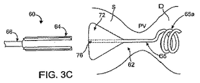
図3A−3Cを参照すると、代替の実施例では、医療デバイス送出カテーテル60は、好適に、カテーテル本体66と、カテーテル本体66の遠位端に取り付けたポッド64と、カテーテル本体66とポッド64を通ってポッド64の遠位端を越えて延在する引き込み可能な内側シャフト68とを具える。ポッド64は、ミシン目ライン70と、カッタ74を具える。この実施例では、医療デバイス62は、拡張可能な近位部分72と、形状記憶遠位端65を有する遠位部分65を具える。図3Bと3Cに示すように、近位部分72は、内側シャフト68が通過する中央ルーメン76を具える。
Referring to FIGS. 3A-3C, in an alternative embodiment, the medical device delivery catheter 60 preferably includes a
図3Aを参照すると、使用に際して、送出カテーテル60は、ポッド64が患者の胃Sの中に位置し、医療デバイス62の遠位端65を伴う内側シャフト68が、幽門弁PVを少なくとも一部的に通って、時には、図に示すように十二指腸Dの中へ延在している。カテーテル60とデバイス62が、カテーテル60及び/又はデバイス62上の一又はそれ以上の放射線不透過性マーキング、及び/又はカテーテル本体66の外側表面上の深さマーキングで確認することができる所望の展開位置にあると、内側シャフトが引き抜かれる(先端がソリッドな矢印)68。図3Bに示すように、内側シャフト68が遠位部分65から除去されると、形状記憶遠位端65aが、真っ直ぐで展開していない形状から、この場合は、らせん形状の展開形状へ変形する。丸い又は楕円形のボール形状、砂時計形状、カールした渦状形状、その他、などのその他の形状を代替の実施例で使用することができる。遠位端65aは、形状記憶、超弾性材料、ばね荷重、あるいはその他の弾性材料で好適に作って、非展開形状から展開した形状へ動かすことができる。一般的に、展開した形状にある遠位端65aは、十二指腸Dの近位部分内に位置し、幽門弁PVを通って胃Sへ戻らないように設計されている。
Referring to FIG. 3A, in use, the delivery catheter 60 has a pod 64 positioned in the patient's stomach S and an
医療デバイス62の近位部分72を展開するために、ポッド64は、カッタ74を用いてミシン目ライン70に沿って切断される(あるいは、様々な実施例において、破って分離される、あるいははがされる)。図3Cに示すように、近位部分72は、ポッド64から解放されると、拡張し、展開して、拡張した形状を取り、この部分が胃Sの中に残り、幽門弁PVを通って十二指腸Dへ行くことを防止する。カテーテル60の長軸を中心とする医療デバイス62の回転方向は、所望の送出を達成するのにしばしば重要になる。従って、いくつかの実施例では、ミシン目ライン70の方向であって、従って、ポッド64が開く側が、送出時に、所望の医療デバイス62の制御された回転方向を達成するように構成されている。次いで送出カテーテル60が引き抜かれ、医療デバイス62を胃S、幽門弁PVを通って、十二指腸D内の適所に配置する。
To deploy the
送出カテーテル60の様々な実施例は、医療デバイス60の送出を強化及び/又は容易にする追加の特徴を具えていても良い。例えば、いくつかの実施例では、医療デバイス62に対する内側シャフト68の回転方向を、シャフト68に対してデバイス62に「鍵をかける」(keying)ことによって、制御するようにしている。キーイング機能は、デバイス62の非円形断面形状に合った非円形ルーメン(例えば、四角形、三角形、スロット、その他)をカテーテル60に設けることによって達成することができる。代替の実施例では、デバイス62は、デバイス62の長さに沿って(複数箇所に)配置した鍵のかかったアンカを介してシャフト68を係合することができる。一の実施例では、アンカがデバイス62の遠位先端にあるキャストである。このアンカは、シャフト68が係合するスロットを有していても良い。いくつかの実施例では、シャフト68も、一又はそれ以上の形状記憶材料又は超弾性材料を具えており、拘束された形状において医療デバイス62の回復力を相殺する。
Various embodiments of the delivery catheter 60 may include additional features that enhance and / or facilitate delivery of the medical device 60. For example, in some embodiments, the direction of rotation of the
図4を参照すると、一の実施例では、医療デバイス送出カテーテル80が、カテーテル本体86とポッド82を具え、このポッドはより広い近位部分82aと、より狭い遠位部分82bと、これらの間のステップオフ84を具える。ポッド82は、ミシン目88を介して開くことができ、あるいは、代替の実施例では、上述したその他の好適な手段で開くことができる。遠位部分82bを、幽門弁PVを通って進めて、十二指腸D内に遠位端を位置させることができるような形状とサイズを有する。ステップオフ84は、幽門弁PVを通って移動しないような形状とサイズを有する。従って、ポッド82は、ユーザが送出カテーテル80を部分的に幽門弁を通って進め、医療デバイス81を弁にまたがる位置で解放できるように構成されている。送出カテーテル80が十分に前進すると、ステップオフ84は、幽門弁PVにぶつかり、ユーザはこの接触を感じて、カテーテル80が十分に進んだことを知ることができる。医療デバイス81は、次いで、弁にまたがる所望の位置で展開する。代替の実施例(図示せず)では、ポッドではなく医療デバイス自体が、直径にステップオフを具え、完全ではなく、部分的に幽門弁PVを通過できる。
Referring to FIG. 4, in one embodiment, a medical
図5を参照すると、多数の実施例において、医療デバイス送出カテーテル90は、カテーテル本体94と、その内壁に沿って配置された一又はそれ以上の支持部材96と、一又はそれ以上のミシン目セット98を有するポッド92を具える。支持部材96は、例えば、細長い、曲がった、馬蹄形、あるいは、さもなければ、成型されたあるいは接着剤によって壁に取り付けたシリコーン片として構成されたものであってもよい。代替の実施例では、支持部材96は、ステッチ又はケースによって、ポッド92内に取り付けるようにしても良い。更なる実施例では、支持部材96が生体分解性であってもよい。支持部材96は、一般的に、ポッド92を安定させて、医療デバイス91のより狭い部分が配置されている領域において屈曲したり湾曲したりしないように構成されている。別の実施例では、支持部材96は、ポッド92の壁の中に埋め込まれていても良く、金属などのその他の材料を具えていても良い。
Referring to FIG. 5, in many embodiments, the medical
図7A−7Cを参照すると、医療デバイス送出カテーテル100の別の実施例が示されており、ポッド102を開く方法が示されている。ポッド102は、二本のミシン目セット104と、ポッド102に沿って延在し、取り付け部材108を介して遠位端に取り付けられているコード106を具えている。コード106が近位側に引っ張られると(先端がソリッドな矢印)、図7Bに示すようにポッド102の一部がはがれ、従って、ポッド102の内部109が露出する。典型的には、医療デバイス(図示せず)は内部109に収納されており、従って、ポッド102がはがれると解放される。コード106が近位側に更に引っ張られると(先端がソリッドな矢印)、図7Cに示すように、ポッド102が更にはがれて開く。様々な実施例では、ポッド102は、複数の様々なミシン目、スリット、ホール、薄い材料部分など、はがす、破る、切断する、あるいは、ポッド102を開くためのその他の手段のうちのいずれを有していても良い。
Referring to FIGS. 7A-7C, another embodiment of the medical
上記は、本発明の完全で正確な記載であるが、様々な変形例、追加、その他のうちのいずれも、本発明の範囲から外れない限り上述した実施例に行うことができる。例えば、上述したデバイスと方法を用いて、あらゆる好適な状態を取り扱い、あるいは、胃腸管内で好適な機能を実行することができる。したがって、上述の記載は、主に例示的な目的で提供されており、特許請求の範囲で規定される本発明の範囲を制限すると解釈するべきではない。 While the above is a complete and accurate description of the invention, any of the various modifications, additions, and others can be made to the embodiments described above without departing from the scope of the invention. For example, the devices and methods described above can be used to handle any suitable condition or perform suitable functions within the gastrointestinal tract. Therefore, the above description is provided primarily for exemplary purposes and should not be construed as limiting the scope of the invention as defined in the claims.
Claims (82)
近位端及び遠位端を有する細長カテーテル本体と;
前記カテーテル本体の前記遠位端に連結され、前記位置へ送出している間は前記医療デバイスを収納し、前記医療デバイスを開いて解放するように構成されたポッドと;
前記ポッドと前記医療デバイスのうちの少なくとも一方に連結された少なくとも一の遠位アクチュエータであって、前記ポッドが開くのを促進するように構成された遠位アクチュエータと;
を具えることを特徴とする装置。 In an apparatus for delivering a medical device to a location within a patient's body:
An elongate catheter body having a proximal end and a distal end;
A pod coupled to the distal end of the catheter body and configured to receive the medical device and to open and release the medical device during delivery to the position;
At least one distal actuator coupled to at least one of the pod and the medical device, the distal actuator configured to facilitate opening of the pod;
A device characterized by comprising.
前記医療デバイスを解放可能に収納する少なくとも二つの対向するハウジング部材と;及び
前記ハウジング部材に移動可能に連結した少なくとも一のヒンジを具え、前記ハウジング部材が前記ヒンジに対して移動して、前記ポッドを開くように構成されていることを特徴とする装置。 The apparatus of claim 1, wherein the pod is:
At least two opposing housing members for releasably housing the medical device; and at least one hinge movably coupled to the housing member, the housing member being moved relative to the hinge, wherein the pod A device characterized in that it is configured to open.
前記医療デバイスに接触して押圧する前記ポッドの近位端近傍に配置したプラットフォームと;及び
前記プラットフォームに連結され、前記カテーテル本体を通ってその近位端へ延在して、ユーザが前記プラットフォームを前進及び後退できるようにする細長シャフトと;
を具えることを特徴とする装置。 35. The apparatus of claim 34, wherein the pusher member is:
A platform disposed near the proximal end of the pod that contacts and presses against the medical device; and is coupled to the platform and extends through the catheter body to the proximal end so that a user can move the platform. An elongate shaft that allows advancement and retraction;
A device characterized by comprising.
十二指腸内に位置させる遠位部分と;
胃の中に位置させる近位部分と;及び
前記遠位部分を前記近位部分に連結して、前記幽門弁を通って延在するように構成された細長連結部分と;
を具えることを特徴とする装置。 54. The apparatus of claim 53, wherein the device is:
A distal portion located in the duodenum;
A proximal portion positioned in the stomach; and an elongated connecting portion configured to connect the distal portion to the proximal portion and extend through the pyloric valve;
A device characterized by comprising.
近位端及び遠位端を有する細長カテーテル本体と;及び
前記カテーテル本体の遠位端に連結され、前記位置へ送出する間は前記医療デバイスを収納して、前記医療デバイスを開いて解放するように構成されたポッドと;を具え、
前記ポッドが前記位置に配置された後に自動的に開くように構成されていることを特徴とする装置。 In an apparatus for delivering a medical device to a location within a patient's body:
An elongate catheter body having a proximal end and a distal end; and coupled to the distal end of the catheter body for receiving the medical device during delivery to the position to open and release the medical device. A pod configured with:
An apparatus configured to automatically open after the pod is placed in the position.
近位端及び遠位端を有する細長カテーテル本体と;
前記カテーテル本体の前記遠位端に連結され、前記位置へ送出する間は前記医療デバイスを収納し、前記医療デバイスを開いて解放するように構成されたポッドと;
前記ポッドと前記医療デバイスのうちの少なくとも一方に連結された少なくとも一の遠位アクチュエータであって、前記ポッドを開くのを促進するように構成された遠位アクチュエータと;及び
前記ポッド内に解放可能に収納された医療デバイスと;
を具えることを特徴とするシステム。 In a system for delivering a medical device to a location within a patient's body:
An elongate catheter body having a proximal end and a distal end;
A pod coupled to the distal end of the catheter body and configured to receive the medical device and to open and release the medical device during delivery to the position;
At least one distal actuator coupled to at least one of the pod and the medical device, the distal actuator configured to facilitate opening the pod; and releasable within the pod Medical devices housed in;
A system characterized by comprising.
十二指腸内に位置させる遠位部分と;
胃の中に位置させる近位部分と;
前記遠位部分を前記近位部分に連結して、前記幽門弁にわたって延在するように構成された細長連結部分と;
を具えることを特徴とするシステム。 64. The system of claim 63, wherein the device is:
A distal portion located in the duodenum;
A proximal portion located in the stomach;
An elongate connection portion configured to connect the distal portion to the proximal portion and extend across the pyloric valve;
A system characterized by comprising.
細長カテーテルの遠位端にあるポッドを前記本体の位置に進めるステップと;及び
前記ポッドと前記医療デバイスのうちの少なくとも一つに連結したアクチュエータを始動して前記ポッドを開くステップとを具え、
前記ポッドを開くことで前記医療デバイスを解放することを特徴とする方法。 In a method of delivering a medical device to a location within a patient's body, the method includes:
Advancing a pod at the distal end of the elongate catheter to the position of the body; and activating an actuator coupled to at least one of the pod and the medical device to open the pod;
Opening the pod to release the medical device.
Applications Claiming Priority (2)
| Application Number | Priority Date | Filing Date | Title |
|---|---|---|---|
| US10/974,482 US7347868B2 (en) | 2004-10-26 | 2004-10-26 | Medical device delivery catheter |
| PCT/US2005/038842 WO2006047708A2 (en) | 2004-10-26 | 2005-10-25 | Medical device delivery catheter |
Publications (1)
| Publication Number | Publication Date |
|---|---|
| JP2008517677A true JP2008517677A (en) | 2008-05-29 |
Family
ID=36207071
Family Applications (1)
| Application Number | Title | Priority Date | Filing Date |
|---|---|---|---|
| JP2007538197A Pending JP2008517677A (en) | 2004-10-26 | 2005-10-25 | Medical device delivery catheter |
Country Status (6)
| Country | Link |
|---|---|
| US (3) | US7347868B2 (en) |
| EP (1) | EP1804678A4 (en) |
| JP (1) | JP2008517677A (en) |
| AU (1) | AU2005299614B2 (en) |
| CA (1) | CA2585430A1 (en) |
| WO (1) | WO2006047708A2 (en) |
Cited By (10)
| Publication number | Priority date | Publication date | Assignee | Title |
|---|---|---|---|---|
| JP4832448B2 (en) * | 2004-12-27 | 2011-12-07 | スパッツ エフジーアイエー、インコーポレイティッド | Gastrointestinal floating anchor |
| US8403952B2 (en) | 2004-12-27 | 2013-03-26 | Spatz-Fgia, Inc. | Floating gastrointestinal anchor |
| US8430894B2 (en) | 2006-03-28 | 2013-04-30 | Spatz-Fgia, Inc. | Floating gastrointestinal anchor |
| US9974680B2 (en) | 2004-12-27 | 2018-05-22 | Spatz Fgia, Inc. | System and methods for internalization of external components of adjustable intragastric balloon |
| JP2018126221A (en) * | 2017-02-06 | 2018-08-16 | 川澄化学工業株式会社 | Catheter for delivery and device for delivering intravascular retainer |
| JP2018186895A (en) * | 2017-04-28 | 2018-11-29 | 川澄化学工業株式会社 | Catheter for transportation, and intravascular detention tool transport device |
| JP2018202153A (en) * | 2017-06-05 | 2018-12-27 | 川澄化学工業株式会社 | Transport catheter and intravascular indwelling device transport device |
| US10857019B2 (en) | 2012-11-26 | 2020-12-08 | Spatz Fgia, Inc. | System and methods for internalization of external components of an adjustable intragastric balloon |
| US10893966B2 (en) | 2017-02-09 | 2021-01-19 | Spatz FGIA Ltd | Check valve with docking station for gastrointestinal balloon |
| JP2022009603A (en) * | 2013-02-21 | 2022-01-14 | ボストン サイエンティフィック サイムド,インコーポレイテッド | Stent for forming anastomosis and medical device comprising the same |
Families Citing this family (154)
| Publication number | Priority date | Publication date | Assignee | Title |
|---|---|---|---|---|
| US6746483B1 (en) * | 2000-03-16 | 2004-06-08 | Smith & Nephew, Inc. | Sheaths for implantable fixation devices |
| US9060844B2 (en) | 2002-11-01 | 2015-06-23 | Valentx, Inc. | Apparatus and methods for treatment of morbid obesity |
| US7572228B2 (en) * | 2004-01-13 | 2009-08-11 | Remon Medical Technologies Ltd | Devices for fixing a sensor in a lumen |
| US20070208252A1 (en) | 2004-04-21 | 2007-09-06 | Acclarent, Inc. | Systems and methods for performing image guided procedures within the ear, nose, throat and paranasal sinuses |
| US8932276B1 (en) | 2004-04-21 | 2015-01-13 | Acclarent, Inc. | Shapeable guide catheters and related methods |
| US10188413B1 (en) | 2004-04-21 | 2019-01-29 | Acclarent, Inc. | Deflectable guide catheters and related methods |
| US7803150B2 (en) | 2004-04-21 | 2010-09-28 | Acclarent, Inc. | Devices, systems and methods useable for treating sinusitis |
| US7654997B2 (en) | 2004-04-21 | 2010-02-02 | Acclarent, Inc. | Devices, systems and methods for diagnosing and treating sinusitus and other disorders of the ears, nose and/or throat |
| US9351750B2 (en) * | 2004-04-21 | 2016-05-31 | Acclarent, Inc. | Devices and methods for treating maxillary sinus disease |
| US8764729B2 (en) | 2004-04-21 | 2014-07-01 | Acclarent, Inc. | Frontal sinus spacer |
| US20070167682A1 (en) * | 2004-04-21 | 2007-07-19 | Acclarent, Inc. | Endoscopic methods and devices for transnasal procedures |
| US20060004323A1 (en) | 2004-04-21 | 2006-01-05 | Exploramed Nc1, Inc. | Apparatus and methods for dilating and modifying ostia of paranasal sinuses and other intranasal or paranasal structures |
| US7462175B2 (en) * | 2004-04-21 | 2008-12-09 | Acclarent, Inc. | Devices, systems and methods for treating disorders of the ear, nose and throat |
| US9089258B2 (en) | 2004-04-21 | 2015-07-28 | Acclarent, Inc. | Endoscopic methods and devices for transnasal procedures |
| US8747389B2 (en) | 2004-04-21 | 2014-06-10 | Acclarent, Inc. | Systems for treating disorders of the ear, nose and throat |
| US8702626B1 (en) | 2004-04-21 | 2014-04-22 | Acclarent, Inc. | Guidewires for performing image guided procedures |
| US20190314620A1 (en) | 2004-04-21 | 2019-10-17 | Acclarent, Inc. | Apparatus and methods for dilating and modifying ostia of paranasal sinuses and other intranasal or paranasal structures |
| US7419497B2 (en) | 2004-04-21 | 2008-09-02 | Acclarent, Inc. | Methods for treating ethmoid disease |
| US8894614B2 (en) | 2004-04-21 | 2014-11-25 | Acclarent, Inc. | Devices, systems and methods useable for treating frontal sinusitis |
| US7559925B2 (en) | 2006-09-15 | 2009-07-14 | Acclarent Inc. | Methods and devices for facilitating visualization in a surgical environment |
| US9399121B2 (en) | 2004-04-21 | 2016-07-26 | Acclarent, Inc. | Systems and methods for transnasal dilation of passageways in the ear, nose or throat |
| US9554691B2 (en) | 2004-04-21 | 2017-01-31 | Acclarent, Inc. | Endoscopic methods and devices for transnasal procedures |
| US20060063973A1 (en) | 2004-04-21 | 2006-03-23 | Acclarent, Inc. | Methods and apparatus for treating disorders of the ear, nose and throat |
| WO2005110280A2 (en) | 2004-05-07 | 2005-11-24 | Valentx, Inc. | Devices and methods for attaching an endolumenal gastrointestinal implant |
| US7347868B2 (en) * | 2004-10-26 | 2008-03-25 | Baronova, Inc. | Medical device delivery catheter |
| US20060122522A1 (en) * | 2004-12-03 | 2006-06-08 | Abhi Chavan | Devices and methods for positioning and anchoring implantable sensor devices |
| US10390714B2 (en) | 2005-01-12 | 2019-08-27 | Remon Medical Technologies, Ltd. | Devices for fixing a sensor in a lumen |
| US8951225B2 (en) | 2005-06-10 | 2015-02-10 | Acclarent, Inc. | Catheters with non-removable guide members useable for treatment of sinusitis |
| US7816975B2 (en) * | 2005-09-20 | 2010-10-19 | Hewlett-Packard Development Company, L.P. | Circuit and method for bias voltage generation |
| US8060214B2 (en) * | 2006-01-05 | 2011-11-15 | Cardiac Pacemakers, Inc. | Implantable medical device with inductive coil configurable for mechanical fixation |
| US8211114B2 (en) | 2006-04-24 | 2012-07-03 | Ethicon Endo-Surgery, Inc. | Medical instrument having a medical snare |
| US20070250012A1 (en) * | 2006-04-24 | 2007-10-25 | Ifung Lu | Medical instrument having a medical needle-knife |
| US9138250B2 (en) * | 2006-04-24 | 2015-09-22 | Ethicon Endo-Surgery, Inc. | Medical instrument handle and medical instrument having a handle |
| US7837620B2 (en) | 2006-04-25 | 2010-11-23 | Ethicon Endo-Surgery, Inc. | Medical tubular assembly |
| US7927327B2 (en) * | 2006-04-25 | 2011-04-19 | Ethicon Endo-Surgery, Inc. | Medical instrument having an articulatable end effector |
| US20070255312A1 (en) * | 2006-05-01 | 2007-11-01 | Ifung Lu | Medical instrument having an end-effector-associated member |
| US7758593B2 (en) * | 2006-05-04 | 2010-07-20 | Ethicon Endo-Surgery, Inc. | Medical instrument handle and medical instrument having same |
| US7597661B2 (en) * | 2006-05-11 | 2009-10-06 | Ethicon Endo-Surgery, Inc. | Medical instrument having a catheter and method for using a catheter |
| US7959642B2 (en) * | 2006-05-16 | 2011-06-14 | Ethicon Endo-Surgery, Inc. | Medical instrument having a needle knife |
| US20070270639A1 (en) * | 2006-05-17 | 2007-11-22 | Long Gary L | Medical instrument having a catheter and having a catheter accessory device and method for using |
| US7892166B2 (en) * | 2006-05-18 | 2011-02-22 | Ethicon Endo-Surgery, Inc. | Medical instrument including a catheter having a catheter stiffener and method for using |
| US8439961B2 (en) * | 2006-07-31 | 2013-05-14 | Boston Scientific Scimed, Inc. | Stent retaining mechanisms |
| ES2369203T3 (en) * | 2006-09-15 | 2011-11-28 | Cardiac Pacemakers, Inc. | ANCHORAGE FOR AN IMPLANTABLE MEDICAL DEVICE. |
| US8676349B2 (en) | 2006-09-15 | 2014-03-18 | Cardiac Pacemakers, Inc. | Mechanism for releasably engaging an implantable medical device for implantation |
| US20080071248A1 (en) * | 2006-09-15 | 2008-03-20 | Cardiac Pacemakers, Inc. | Delivery stystem for an implantable physiologic sensor |
| WO2008057720A1 (en) * | 2006-11-08 | 2008-05-15 | Cardiac Pacemakers, Inc. | Implant for securing a sensor in a vessel |
| WO2008096362A1 (en) * | 2007-02-07 | 2008-08-14 | Duocure, Inc. | Duodenal stimulation devices and methods for the treatment of conditions relating to eating disorders |
| WO2008124787A2 (en) * | 2007-04-09 | 2008-10-16 | Acclarent, Inc. | Ethmoidotomy system and implantable spacer devices having therapeutic substance delivery capability for treatment of paranasal sinusitis |
| US20100121371A1 (en) * | 2007-04-30 | 2010-05-13 | Spatz Fgia, Inc. | Non-endoscopic insertion and removal of a device |
| US8204599B2 (en) * | 2007-05-02 | 2012-06-19 | Cardiac Pacemakers, Inc. | System for anchoring an implantable sensor in a vessel |
| US20080283066A1 (en) * | 2007-05-17 | 2008-11-20 | Cardiac Pacemakers, Inc. | Delivery device for implantable sensors |
| US7634318B2 (en) | 2007-06-14 | 2009-12-15 | Cardiac Pacemakers, Inc. | Multi-element acoustic recharging system |
| EP2178597A4 (en) | 2007-07-24 | 2010-09-22 | Betastim Ltd | Duodenal eating sensor |
| WO2009033049A1 (en) * | 2007-09-07 | 2009-03-12 | Baronova, Inc. | Device for intermittently obstructing a gastric opening and method of use |
| CA2701576C (en) | 2007-10-17 | 2016-06-21 | Angiomed Gmbh & Co. Medizintechnik Kg | Delivery system for a self-expanding device for placement in a bodily lumen |
| US8915951B2 (en) * | 2008-02-11 | 2014-12-23 | Boston Scientific Scimed, Inc. | Self-expandable stent with a constrictive coating and method of use |
| WO2009105699A1 (en) | 2008-02-22 | 2009-08-27 | Endologix, Inc. | Design and method of placement of a graft or graft system |
| US8545544B2 (en) * | 2008-04-03 | 2013-10-01 | Gardia Medical Ltd. | Delivery catheter with constraining sheath and methods of deploying medical devices into a body lumen |
| US8236040B2 (en) * | 2008-04-11 | 2012-08-07 | Endologix, Inc. | Bifurcated graft deployment systems and methods |
| GB0815339D0 (en) * | 2008-08-21 | 2008-10-01 | Angiomed Ag | Method of loading a stent into a sheath |
| CA2720466A1 (en) * | 2008-05-09 | 2009-11-12 | Juergen Dorn | Method of loading a stent into a sheath |
| US8211053B2 (en) | 2008-05-13 | 2012-07-03 | Equilibrate, Llc | Interosmolar fluid removal |
| US9750625B2 (en) | 2008-06-11 | 2017-09-05 | C.R. Bard, Inc. | Catheter delivery device |
| GB0810749D0 (en) | 2008-06-11 | 2008-07-16 | Angiomed Ag | Catherter delivery device |
| WO2010002786A2 (en) * | 2008-06-30 | 2010-01-07 | Rafael Fleites | Method and system for endoscopic placement of a balloon |
| EP2296536A1 (en) * | 2008-07-15 | 2011-03-23 | Cardiac Pacemakers, Inc. | Implant assist apparatus for acoustically enabled implantable medical device |
| JP5584687B2 (en) | 2008-09-18 | 2014-09-03 | アクラレント インコーポレイテッド | Method and apparatus for treating ear, nose and throat disorders |
| GB0823716D0 (en) | 2008-12-31 | 2009-02-04 | Angiomed Ag | Stent delivery device with rolling stent retaining sheath |
| US8694129B2 (en) | 2009-02-13 | 2014-04-08 | Cardiac Pacemakers, Inc. | Deployable sensor platform on the lead system of an implantable device |
| DE102009018723A1 (en) * | 2009-04-27 | 2010-10-28 | Karl Storz Gmbh & Co. Kg | Medical dilatation instrument |
| EP2429452B1 (en) | 2009-04-28 | 2020-01-15 | Endologix, Inc. | Endoluminal prosthesis system |
| CN102639086A (en) * | 2009-09-10 | 2012-08-15 | 挪威斯腾特公司 | Vascular prosthesis assembly with retention mechanism and method |
| GB0921240D0 (en) * | 2009-12-03 | 2010-01-20 | Angiomed Ag | Stent device delivery system and method of making such |
| GB0921238D0 (en) | 2009-12-03 | 2010-01-20 | Angiomed Ag | Stent device delivery system and method of making such |
| GB0921236D0 (en) * | 2009-12-03 | 2010-01-20 | Angiomed Ag | Stent device delivery system and method of making such |
| GB0921237D0 (en) | 2009-12-03 | 2010-01-20 | Angiomed Ag | Stent device delivery system and method of making such |
| US8870950B2 (en) | 2009-12-08 | 2014-10-28 | Mitral Tech Ltd. | Rotation-based anchoring of an implant |
| US20110184509A1 (en) * | 2010-01-27 | 2011-07-28 | Abbott Laboratories | Dual sheath assembly and method of use |
| US20110208292A1 (en) * | 2010-02-19 | 2011-08-25 | Abbott Laboratories | Hinged sheath assembly and method of use |
| WO2011111047A2 (en) | 2010-03-10 | 2011-09-15 | Mitraltech Ltd. | Prosthetic mitral valve with tissue anchors |
| US8628554B2 (en) | 2010-06-13 | 2014-01-14 | Virender K. Sharma | Intragastric device for treating obesity |
| US10010439B2 (en) | 2010-06-13 | 2018-07-03 | Synerz Medical, Inc. | Intragastric device for treating obesity |
| US9526648B2 (en) | 2010-06-13 | 2016-12-27 | Synerz Medical, Inc. | Intragastric device for treating obesity |
| US10420665B2 (en) | 2010-06-13 | 2019-09-24 | W. L. Gore & Associates, Inc. | Intragastric device for treating obesity |
| US9763657B2 (en) | 2010-07-21 | 2017-09-19 | Mitraltech Ltd. | Techniques for percutaneous mitral valve replacement and sealing |
| US11653910B2 (en) | 2010-07-21 | 2023-05-23 | Cardiovalve Ltd. | Helical anchor implantation |
| EP2595693B1 (en) | 2010-07-22 | 2015-03-04 | Endobetix Ltd | Pancreatiobiliary diversion device |
| US10111767B2 (en) | 2010-10-29 | 2018-10-30 | Abbott Cardiovascular Systems Inc. | Sheaths used in polymer scaffold delivery systems |
| EP2635241B1 (en) | 2010-11-02 | 2019-02-20 | Endologix, Inc. | Apparatus for placement of a graft or graft system |
| GB201020373D0 (en) | 2010-12-01 | 2011-01-12 | Angiomed Ag | Device to release a self-expanding implant |
| US20120172887A1 (en) | 2011-01-05 | 2012-07-05 | Wilson-Cook Medical, Inc. d/b/a Cook Endoscopy | Proximal Release Expandable Prosthesis Delivery System |
| US8414528B2 (en) | 2011-05-27 | 2013-04-09 | Abbott Cardiovascular Systems Inc. | Polymer scaffold sheaths |
| US8852257B2 (en) | 2011-06-21 | 2014-10-07 | Abbott Cardiovascular Systems Inc. | Sheaths used with polymer scaffold |
| US8852272B2 (en) | 2011-08-05 | 2014-10-07 | Mitraltech Ltd. | Techniques for percutaneous mitral valve replacement and sealing |
| US20140324164A1 (en) * | 2011-08-05 | 2014-10-30 | Mitraltech Ltd. | Techniques for percutaneous mitral valve replacement and sealing |
| WO2013021374A2 (en) | 2011-08-05 | 2013-02-14 | Mitraltech Ltd. | Techniques for percutaneous mitral valve replacement and sealing |
| EP2739214B1 (en) | 2011-08-05 | 2018-10-10 | Cardiovalve Ltd | Percutaneous mitral valve replacement and sealing |
| US10213329B2 (en) | 2011-08-12 | 2019-02-26 | W. L. Gore & Associates, Inc. | Evertable sheath devices, systems, and methods |
| US9011514B2 (en) * | 2011-08-22 | 2015-04-21 | Cook Medical Technologies Llc | Emergency vessel repair prosthesis deployment system |
| US9089399B2 (en) * | 2011-09-17 | 2015-07-28 | Katalyst Surgical, Llc | Steerable laser probe |
| US9168352B2 (en) | 2011-12-19 | 2015-10-27 | Cardiacassist, Inc. | Dual lumen cannula |
| US9173759B2 (en) | 2012-05-31 | 2015-11-03 | Valentx, Inc. | Devices and methods for gastrointestinal bypass |
| US20130324906A1 (en) | 2012-05-31 | 2013-12-05 | Valen Tx, Inc. | Devices and methods for gastrointestinal bypass |
| US9681975B2 (en) | 2012-05-31 | 2017-06-20 | Valentx, Inc. | Devices and methods for gastrointestinal bypass |
| US8628571B1 (en) | 2012-11-13 | 2014-01-14 | Mitraltech Ltd. | Percutaneously-deliverable mechanical valve |
| US9072590B2 (en) | 2012-12-07 | 2015-07-07 | Abbott Cardiovascular Systems Inc. | Sheaths reducing recoil and loss of retention for polymer scaffolds crimped to balloons |
| EP2948103B1 (en) | 2013-01-24 | 2022-12-07 | Cardiovalve Ltd | Ventricularly-anchored prosthetic valves |
| US9763819B1 (en) | 2013-03-05 | 2017-09-19 | W. L. Gore & Associates, Inc. | Tapered sleeve |
| US9757264B2 (en) | 2013-03-13 | 2017-09-12 | Valentx, Inc. | Devices and methods for gastrointestinal bypass |
| US9675483B2 (en) | 2013-06-21 | 2017-06-13 | Abbott Cardiovascular Systems Inc. | Protective sheath assembly for a polymer scaffold |
| US9788983B2 (en) | 2013-06-21 | 2017-10-17 | Abbott Cardiovascular Systems Inc. | Removable sheath assembly for a polymer scaffold |
| US10098771B2 (en) | 2013-09-25 | 2018-10-16 | Abbott Cardiovascular Systems Inc. | Clip sheath for a polymer scaffold |
| US9907641B2 (en) | 2014-01-10 | 2018-03-06 | W. L. Gore & Associates, Inc. | Implantable intraluminal device |
| WO2015120155A1 (en) * | 2014-02-06 | 2015-08-13 | Boston Scientific Scimed, Inc. | Occlusion device detachable by inflation of a balloon |
| US9913958B2 (en) | 2014-02-28 | 2018-03-13 | Abbott Cardiovascular Systems Inc. | Protective sheaths for medical devices |
| US10966850B2 (en) | 2014-03-06 | 2021-04-06 | W. L. Gore & Associates, Inc. | Implantable medical device constraint and deployment apparatus |
| US9364361B2 (en) | 2014-03-13 | 2016-06-14 | Abbott Cardiovascular Systems Inc. | Striped sheaths for medical devices |
| US9510976B2 (en) * | 2014-04-29 | 2016-12-06 | Abbott Cardiovascular Systems Inc. | Devices and methods for treatment of the Eustachian tube and sinus cavity |
| EP3137016A4 (en) | 2014-04-30 | 2018-01-24 | Lean Medical Technologies, LLC | Gastrointestinal device |
| US9414947B2 (en) * | 2014-05-13 | 2016-08-16 | Covidien Lp | Gastric tubes having tethered plugs and methods of use |
| WO2016016899A1 (en) | 2014-07-30 | 2016-02-04 | Mitraltech Ltd. | Articulatable prosthetic valve |
| US10569063B2 (en) | 2014-10-03 | 2020-02-25 | W. L. Gore & Associates, Inc. | Removable covers for drug eluting medical devices |
| CN110141399B (en) | 2015-02-05 | 2021-07-27 | 卡迪尔维尔福股份有限公司 | Prosthetic valve with axially sliding frame |
| US9974651B2 (en) | 2015-02-05 | 2018-05-22 | Mitral Tech Ltd. | Prosthetic valve with axially-sliding frames |
| US10118035B2 (en) | 2015-02-24 | 2018-11-06 | Elira, Inc. | Systems and methods for enabling appetite modulation and/or improving dietary compliance using an electro-dermal patch |
| US20220062621A1 (en) | 2015-02-24 | 2022-03-03 | Elira, Inc. | Electrical Stimulation-Based Weight Management System |
| US9956393B2 (en) | 2015-02-24 | 2018-05-01 | Elira, Inc. | Systems for increasing a delay in the gastric emptying time for a patient using a transcutaneous electro-dermal patch |
| US10765863B2 (en) | 2015-02-24 | 2020-09-08 | Elira, Inc. | Systems and methods for using a transcutaneous electrical stimulation device to deliver titrated therapy |
| US10864367B2 (en) | 2015-02-24 | 2020-12-15 | Elira, Inc. | Methods for using an electrical dermal patch in a manner that reduces adverse patient reactions |
| US10376145B2 (en) | 2015-02-24 | 2019-08-13 | Elira, Inc. | Systems and methods for enabling a patient to achieve a weight loss objective using an electrical dermal patch |
| US10335302B2 (en) | 2015-02-24 | 2019-07-02 | Elira, Inc. | Systems and methods for using transcutaneous electrical stimulation to enable dietary interventions |
| US9757574B2 (en) | 2015-05-11 | 2017-09-12 | Rainbow Medical Ltd. | Dual chamber transvenous pacemaker |
| WO2017004265A1 (en) | 2015-06-30 | 2017-01-05 | Endologix, Inc. | Locking assembly for coupling guidewire to delivery system |
| US10531866B2 (en) | 2016-02-16 | 2020-01-14 | Cardiovalve Ltd. | Techniques for providing a replacement valve and transseptal communication |
| US10779980B2 (en) | 2016-04-27 | 2020-09-22 | Synerz Medical, Inc. | Intragastric device for treating obesity |
| EP3496664B1 (en) | 2016-08-10 | 2021-09-29 | Cardiovalve Ltd | Prosthetic valve with concentric frames |
| USD800908S1 (en) | 2016-08-10 | 2017-10-24 | Mitraltech Ltd. | Prosthetic valve element |
| US11426276B2 (en) * | 2016-10-12 | 2022-08-30 | Medtronic Vascular, Inc. | Stented prosthetic heart valve delivery system having an expandable bumper |
| EP3551140A4 (en) | 2016-12-09 | 2020-07-08 | Zenflow, Inc. | Systems, devices, and methods for the accurate deployment of an implant in the prostatic urethra |
| US11246704B2 (en) | 2017-08-03 | 2022-02-15 | Cardiovalve Ltd. | Prosthetic heart valve |
| US10575948B2 (en) | 2017-08-03 | 2020-03-03 | Cardiovalve Ltd. | Prosthetic heart valve |
| US11793633B2 (en) | 2017-08-03 | 2023-10-24 | Cardiovalve Ltd. | Prosthetic heart valve |
| US10537426B2 (en) | 2017-08-03 | 2020-01-21 | Cardiovalve Ltd. | Prosthetic heart valve |
| US10888421B2 (en) | 2017-09-19 | 2021-01-12 | Cardiovalve Ltd. | Prosthetic heart valve with pouch |
| US10933247B2 (en) * | 2017-08-21 | 2021-03-02 | MRM MedTech, LLC | Lead with integrated features to facilitate extraction and associated methods of extraction |
| US11865334B2 (en) * | 2017-08-21 | 2024-01-09 | MRM MedTech, LLC | Lead with integrated feature including a low friction component to facilitate extraction and associated methods of extraction |
| CA3077748C (en) | 2017-10-11 | 2023-01-03 | W. L. Gore & Associates, Inc | Implantable medical device constraint and deployment apparatus |
| GB201720803D0 (en) | 2017-12-13 | 2018-01-24 | Mitraltech Ltd | Prosthetic Valve and delivery tool therefor |
| GB201800399D0 (en) | 2018-01-10 | 2018-02-21 | Mitraltech Ltd | Temperature-control during crimping of an implant |
| US20200129164A1 (en) * | 2018-10-24 | 2020-04-30 | M-V Arterica AB | Self-expanding hemostatic devices and methods for fascia and vessel passages |
| EP4061244A1 (en) | 2019-11-19 | 2022-09-28 | Arterica Inc. | Vascular closure devices and methods |
| WO2021101951A1 (en) | 2019-11-19 | 2021-05-27 | Zenflow, Inc. | Systems, devices, and methods for the accurate deployment and imaging of an implant in the prostatic urethra |
| CN115279442A (en) * | 2020-03-10 | 2022-11-01 | 波士顿科学国际有限公司 | Method for coupling components of an installation and associated installation with these components |
| CN111904677B (en) * | 2020-09-14 | 2021-06-01 | 艾柯医疗器械(北京)有限公司 | Stent delivery member, stent delivery system, and stent system |
Citations (1)
| Publication number | Priority date | Publication date | Assignee | Title |
|---|---|---|---|---|
| JPH08173548A (en) * | 1994-08-12 | 1996-07-09 | Cardiovascular Concepts Inc | Equipment and method for release arrangement of artificial organ in pipe cavity |
Family Cites Families (29)
| Publication number | Priority date | Publication date | Assignee | Title |
|---|---|---|---|---|
| US5222970A (en) * | 1991-09-06 | 1993-06-29 | William A. Cook Australia Pty. Ltd. | Method of and system for mounting a vascular occlusion balloon on a delivery catheter |
| FR2688688A1 (en) * | 1992-03-12 | 1993-09-24 | Richard Thierry | Tool for fitting an autoexpansible endoprosthesis for human or animal tubular organ |
| IT1260485B (en) | 1992-05-29 | 1996-04-09 | PROCEDURE AND DEVICE FOR THE TREATMENT OF THE OBESITY OF A PATIENT | |
| US5824041A (en) * | 1994-06-08 | 1998-10-20 | Medtronic, Inc. | Apparatus and methods for placement and repositioning of intraluminal prostheses |
| US5765682A (en) * | 1994-10-13 | 1998-06-16 | Menlo Care, Inc. | Restrictive package for expandable or shape memory medical devices and method of preventing premature change of same |
| US5782916A (en) | 1996-08-13 | 1998-07-21 | Galt Laboratories, Inc. | Device for maintaining urinary continence |
| US6254628B1 (en) * | 1996-12-09 | 2001-07-03 | Micro Therapeutics, Inc. | Intracranial stent |
| FR2765098A1 (en) * | 1997-06-25 | 1998-12-31 | Jean Noel Bernard | APPLIANCE FOR LAYING AND RECOVERING PARTS SUCH AS ENDOPROTHESES |
| US5820584A (en) | 1997-08-28 | 1998-10-13 | Crabb; Jerry A. | Duodenal insert and method of use |
| US5895410A (en) * | 1997-09-12 | 1999-04-20 | B. Braun Medical, Inc. | Introducer for an expandable vascular occlusion device |
| FR2769491B1 (en) | 1997-10-15 | 2000-01-07 | Patrick Sangouard | ADJUSTABLE ARTIFICIAL SPHINCTER WITH MAGNETIC CONTROL |
| US6254642B1 (en) | 1997-12-09 | 2001-07-03 | Thomas V. Taylor | Perorally insertable gastroesophageal anti-reflux valve prosthesis and tool for implantation thereof |
| US7160312B2 (en) | 1999-06-25 | 2007-01-09 | Usgi Medical, Inc. | Implantable artificial partition and methods of use |
| US6540789B1 (en) | 2000-06-15 | 2003-04-01 | Scimed Life Systems, Inc. | Method for treating morbid obesity |
| US6488962B1 (en) | 2000-06-20 | 2002-12-03 | Depomed, Inc. | Tablet shapes to enhance gastric retention of swellable controlled-release oral dosage forms |
| WO2002011696A2 (en) | 2000-08-08 | 2002-02-14 | Ev & M | Active tissue augmentation materials and method |
| JP4255286B2 (en) | 2001-05-17 | 2009-04-15 | ウィルソン−クック メディカル インコーポレイテッド | Intragastric device for treating obesity |
| US6558400B2 (en) | 2001-05-30 | 2003-05-06 | Satiety, Inc. | Obesity treatment tools and methods |
| US20020188354A1 (en) | 2001-06-12 | 2002-12-12 | Peghini Paolo Lino | Device to treat obesity by obstructing gastric outlet |
| US6951536B2 (en) | 2001-07-30 | 2005-10-04 | Olympus Corporation | Capsule-type medical device and medical system |
| US20040117031A1 (en) * | 2001-08-27 | 2004-06-17 | Stack Richard S. | Satiation devices and methods |
| US6675809B2 (en) * | 2001-08-27 | 2004-01-13 | Richard S. Stack | Satiation devices and methods |
| US6740121B2 (en) | 2001-11-09 | 2004-05-25 | Boston Scientific Corporation | Intragastric stent for duodenum bypass |
| US6755869B2 (en) | 2001-11-09 | 2004-06-29 | Boston Scientific Corporation | Intragastric prosthesis for the treatment of morbid obesity |
| US20030144708A1 (en) | 2002-01-29 | 2003-07-31 | Starkebaum Warren L. | Methods and apparatus for retarding stomach emptying for treatment of eating disorders |
| US6994095B2 (en) | 2003-07-28 | 2006-02-07 | Medventure Associates Iv | Pyloric valve corking device and method |
| US9498366B2 (en) | 2003-07-28 | 2016-11-22 | Baronova, Inc. | Devices and methods for pyloric anchoring |
| US8048169B2 (en) | 2003-07-28 | 2011-11-01 | Baronova, Inc. | Pyloric valve obstructing devices and methods |
| US7347868B2 (en) * | 2004-10-26 | 2008-03-25 | Baronova, Inc. | Medical device delivery catheter |
-
2004
- 2004-10-26 US US10/974,482 patent/US7347868B2/en active Active
-
2005
- 2005-10-25 EP EP05814120A patent/EP1804678A4/en not_active Withdrawn
- 2005-10-25 JP JP2007538197A patent/JP2008517677A/en active Pending
- 2005-10-25 AU AU2005299614A patent/AU2005299614B2/en not_active Ceased
- 2005-10-25 CA CA002585430A patent/CA2585430A1/en not_active Abandoned
- 2005-10-25 WO PCT/US2005/038842 patent/WO2006047708A2/en active Application Filing
-
2008
- 2008-03-14 US US12/049,217 patent/US8070824B2/en not_active Expired - Fee Related
-
2011
- 2011-12-01 US US13/309,434 patent/US8579988B2/en active Active
Patent Citations (1)
| Publication number | Priority date | Publication date | Assignee | Title |
|---|---|---|---|---|
| JPH08173548A (en) * | 1994-08-12 | 1996-07-09 | Cardiovascular Concepts Inc | Equipment and method for release arrangement of artificial organ in pipe cavity |
Cited By (13)
| Publication number | Priority date | Publication date | Assignee | Title |
|---|---|---|---|---|
| JP4832448B2 (en) * | 2004-12-27 | 2011-12-07 | スパッツ エフジーアイエー、インコーポレイティッド | Gastrointestinal floating anchor |
| US8403952B2 (en) | 2004-12-27 | 2013-03-26 | Spatz-Fgia, Inc. | Floating gastrointestinal anchor |
| US9974680B2 (en) | 2004-12-27 | 2018-05-22 | Spatz Fgia, Inc. | System and methods for internalization of external components of adjustable intragastric balloon |
| US8430894B2 (en) | 2006-03-28 | 2013-04-30 | Spatz-Fgia, Inc. | Floating gastrointestinal anchor |
| US8430895B2 (en) | 2006-03-28 | 2013-04-30 | Spatz-Fgia, Inc. | Floating gastrointestinal anchor |
| US10857019B2 (en) | 2012-11-26 | 2020-12-08 | Spatz Fgia, Inc. | System and methods for internalization of external components of an adjustable intragastric balloon |
| JP7300489B2 (en) | 2013-02-21 | 2023-06-29 | ボストン サイエンティフィック サイムド,インコーポレイテッド | Medical devices including stents for forming anastomoses |
| JP2022009603A (en) * | 2013-02-21 | 2022-01-14 | ボストン サイエンティフィック サイムド,インコーポレイテッド | Stent for forming anastomosis and medical device comprising the same |
| JP2018126221A (en) * | 2017-02-06 | 2018-08-16 | 川澄化学工業株式会社 | Catheter for delivery and device for delivering intravascular retainer |
| US10893966B2 (en) | 2017-02-09 | 2021-01-19 | Spatz FGIA Ltd | Check valve with docking station for gastrointestinal balloon |
| JP2018186895A (en) * | 2017-04-28 | 2018-11-29 | 川澄化学工業株式会社 | Catheter for transportation, and intravascular detention tool transport device |
| JP2018202153A (en) * | 2017-06-05 | 2018-12-27 | 川澄化学工業株式会社 | Transport catheter and intravascular indwelling device transport device |
| JP7103721B2 (en) | 2017-06-05 | 2022-07-20 | Sbカワスミ株式会社 | Transport catheter and intravascular indwelling device transport device |
Also Published As
| Publication number | Publication date |
|---|---|
| US8579988B2 (en) | 2013-11-12 |
| WO2006047708A2 (en) | 2006-05-04 |
| AU2005299614A1 (en) | 2006-05-04 |
| US20120165788A1 (en) | 2012-06-28 |
| CA2585430A1 (en) | 2006-05-04 |
| US7347868B2 (en) | 2008-03-25 |
| US8070824B2 (en) | 2011-12-06 |
| AU2005299614A8 (en) | 2011-10-13 |
| EP1804678A2 (en) | 2007-07-11 |
| AU2005299614B2 (en) | 2011-06-16 |
| US20060089627A1 (en) | 2006-04-27 |
| US20080215130A1 (en) | 2008-09-04 |
| WO2006047708A3 (en) | 2009-04-16 |
| EP1804678A4 (en) | 2010-11-03 |
Similar Documents
| Publication | Publication Date | Title |
|---|---|---|
| JP2008517677A (en) | Medical device delivery catheter | |
| JP4005308B2 (en) | Wound closure device | |
| EP2077768B1 (en) | Devices for treating obesity and gerd by intussuscepting a portion of stomach tissue | |
| US20190282234A1 (en) | Tissue retraction devices and related methods of use | |
| TW510788B (en) | Surgical stabilizer devices and methods | |
| JP4508866B2 (en) | Vascular closure clip and delivery device | |
| US7452363B2 (en) | Applier for fastener for single lumen access anastomosis | |
| US20080319435A1 (en) | Shape-changing tissue constrictor and methods of use | |
| EP1520527A1 (en) | Anastomosis device | |
| US20040186514A1 (en) | Flexible device for transfixing and joining tissue | |
| US20060217748A1 (en) | Method for Hybrid Gastro-Jejunostomy | |
| JPH07275203A (en) | Device and method to form anatomic cavity for hernia treatment using abdominal cavity mirror and patch to be usedfor this method | |
| EP2685911A1 (en) | Endoscopic full thickness gastric reduction apparatus and method | |
| JP2020506029A (en) | Apparatus and method for retracting tissue | |
| EP2571429A1 (en) | Devices and methods to deliver, retain, and remove a separating device in an intussuscepted hollow organ | |
| WO2020196336A1 (en) | Anchor instrument | |
| EP3119289B1 (en) | Devices for lumen occlusion | |
| US20210290418A1 (en) | Systems and methods for implanting a gastric bypass device | |
| AU2007201158B2 (en) | Method for hybrid gastro-jejunostomy | |
| KR20240051281A (en) | Devices, systems, and methods for pyloric occlusion | |
| AU2014200828A1 (en) | Methods and devices for treating obesity and GERD by intussuscepting a portion of stomach tissue |
Legal Events
| Date | Code | Title | Description |
|---|---|---|---|
| A621 | Written request for application examination |
Free format text: JAPANESE INTERMEDIATE CODE: A621 Effective date: 20080917 |
|
| A131 | Notification of reasons for refusal |
Free format text: JAPANESE INTERMEDIATE CODE: A131 Effective date: 20110308 |
|
| A601 | Written request for extension of time |
Free format text: JAPANESE INTERMEDIATE CODE: A601 Effective date: 20110524 |
|
| A602 | Written permission of extension of time |
Free format text: JAPANESE INTERMEDIATE CODE: A602 Effective date: 20110531 |
|
| A601 | Written request for extension of time |
Free format text: JAPANESE INTERMEDIATE CODE: A601 Effective date: 20110706 |
|
| A602 | Written permission of extension of time |
Free format text: JAPANESE INTERMEDIATE CODE: A602 Effective date: 20110713 |
|
| A02 | Decision of refusal |
Free format text: JAPANESE INTERMEDIATE CODE: A02 Effective date: 20111018 |