JP2008514916A - Determination of the inflow of the right and left eigenvectors in a Coriolis flowmeter - Google Patents
Determination of the inflow of the right and left eigenvectors in a Coriolis flowmeter Download PDFInfo
- Publication number
- JP2008514916A JP2008514916A JP2007533443A JP2007533443A JP2008514916A JP 2008514916 A JP2008514916 A JP 2008514916A JP 2007533443 A JP2007533443 A JP 2007533443A JP 2007533443 A JP2007533443 A JP 2007533443A JP 2008514916 A JP2008514916 A JP 2008514916A
- Authority
- JP
- Japan
- Prior art keywords
- conduit
- relative phase
- eigenvector
- flow rate
- determining
- Prior art date
- Legal status (The legal status is an assumption and is not a legal conclusion. Google has not performed a legal analysis and makes no representation as to the accuracy of the status listed.)
- Pending
Links
Images


Classifications
-
- G—PHYSICS
- G01—MEASURING; TESTING
- G01F—MEASURING VOLUME, VOLUME FLOW, MASS FLOW OR LIQUID LEVEL; METERING BY VOLUME
- G01F1/00—Measuring the volume flow or mass flow of fluid or fluent solid material wherein the fluid passes through a meter in a continuous flow
- G01F1/76—Devices for measuring mass flow of a fluid or a fluent solid material
- G01F1/78—Direct mass flowmeters
- G01F1/80—Direct mass flowmeters operating by measuring pressure, force, momentum, or frequency of a fluid flow to which a rotational movement has been imparted
- G01F1/84—Coriolis or gyroscopic mass flowmeters
- G01F1/845—Coriolis or gyroscopic mass flowmeters arrangements of measuring means, e.g., of measuring conduits
- G01F1/8468—Coriolis or gyroscopic mass flowmeters arrangements of measuring means, e.g., of measuring conduits vibrating measuring conduits
- G01F1/849—Coriolis or gyroscopic mass flowmeters arrangements of measuring means, e.g., of measuring conduits vibrating measuring conduits having straight measuring conduits
-
- G—PHYSICS
- G01—MEASURING; TESTING
- G01F—MEASURING VOLUME, VOLUME FLOW, MASS FLOW OR LIQUID LEVEL; METERING BY VOLUME
- G01F1/00—Measuring the volume flow or mass flow of fluid or fluent solid material wherein the fluid passes through a meter in a continuous flow
- G01F1/76—Devices for measuring mass flow of a fluid or a fluent solid material
- G01F1/78—Direct mass flowmeters
- G01F1/80—Direct mass flowmeters operating by measuring pressure, force, momentum, or frequency of a fluid flow to which a rotational movement has been imparted
- G01F1/84—Coriolis or gyroscopic mass flowmeters
- G01F1/8409—Coriolis or gyroscopic mass flowmeters constructional details
- G01F1/8436—Coriolis or gyroscopic mass flowmeters constructional details signal processing
-
- G—PHYSICS
- G01—MEASURING; TESTING
- G01F—MEASURING VOLUME, VOLUME FLOW, MASS FLOW OR LIQUID LEVEL; METERING BY VOLUME
- G01F25/00—Testing or calibration of apparatus for measuring volume, volume flow or liquid level or for metering by volume
- G01F25/10—Testing or calibration of apparatus for measuring volume, volume flow or liquid level or for metering by volume of flowmeters
Landscapes
- Physics & Mathematics (AREA)
- Fluid Mechanics (AREA)
- General Physics & Mathematics (AREA)
- Engineering & Computer Science (AREA)
- Signal Processing (AREA)
- Measuring Volume Flow (AREA)
Abstract
振動管路に対する左固有ベクトルの相対位相の周期的計算を可能にする方法及び機器が開示される。通常動作期間に2つの駆動部が連携して使用され、管路(202)の主曲げモードが励起される。周期的に、2つの駆動部のうちの第1の駆動部(204)が、次いで第2の駆動部(206)が使用不能にされ、振動管路についての左固有ベクトルの相対位相の決定(208)を可能にする測定が可能となる。 A method and apparatus is disclosed that allows for periodic calculation of the relative phase of the left eigenvector with respect to the vibrating line. During the normal operation period, the two driving units are used in cooperation to excite the main bending mode of the pipe line (202). Periodically, the first of the two drives (204) and then the second drive (206) are disabled, and the relative phase of the left eigenvector for the vibration line is determined (208). ) Is possible.
Description
本発明は流量計の分野に関し、詳細にはコリオリ流量計に関する。
従来技術の記述
コリオリ流量計では、流体搬送管を正弦運動で振動させ、管の2つ以上の位置で振動応答間の時間遅延(又は位相角)を測定することによって、質量流量が測定される。実際の状況では、時間遅延は質量流量と共に線形に変化するが、時間遅延はゼロ質量流量では一般にゼロではない。通常は、非比例減衰、残留柔軟性応答、電磁気的漏話、計器電子回路での位相遅延などの幾つかの要素によって引き起こされる流量ゼロ遅延又はオフセットが存在する。
The present invention relates to the field of flow meters, and in particular to Coriolis flow meters.
Description of the Prior Art In a Coriolis flow meter, mass flow is measured by vibrating a fluid carrying tube in a sinusoidal motion and measuring the time delay (or phase angle) between the vibration responses at two or more locations on the tube. . In actual situations, the time delay varies linearly with mass flow, but the time delay is generally not zero at zero mass flow. There are usually zero flow delays or offsets caused by several factors such as non-proportional decay, residual flexibility response, electromagnetic crosstalk, phase delay in instrument electronics.
この流量ゼロ・オフセットは、典型的には、流量ゼロ状態での流量ゼロ・オフセットを測定し、この測定したオフセットを後続の流動期間に行った測定値から差し引くことによって補正される。これは、流量ゼロ・オフセットが一定のままである場合に流量ゼロ・オフセット問題を補正するのには十分である。遺憾ながら、流量ゼロ・オフセットは、周囲環境(温度など)の小さな変化、又は材料が流れる配管系の変化に影響を受ける可能性がある。流量ゼロ・オフセットの変化は測定流量の誤差を引き起こす。通常動作期間には、流量ゼロ状態と流量ゼロ状態との間に長い期間が存在し得る。コリオリ流量計は、こうした流量ゼロ状態の期間に流量計をゼロ設定することによって較正することができる。経時的なゼロ・オフセットの変化は、測定流量の著しい誤差を引き起こす可能性がある。したがって、流動期間に流量ゼロ・オフセットを較正するシステム及び方法に対する要求が存在する。 This zero flow offset is typically corrected by measuring the zero flow offset in the zero flow condition and subtracting this measured offset from the measurements taken in subsequent flow periods. This is sufficient to correct the flow zero offset problem when the flow zero offset remains constant. Unfortunately, zero flow offset can be affected by small changes in the surrounding environment (such as temperature) or changes in the piping system through which the material flows. Changes in flow zero offset cause measurement flow error. In the normal operation period, there may be a long period between the zero flow state and the zero flow state. The Coriolis flow meter can be calibrated by zeroing the flow meter during these zero flow conditions. Changes in zero offset over time can cause significant errors in the measured flow rate. Accordingly, there is a need for a system and method for calibrating a zero flow offset during the flow period.
発明の概要
振動管路に対する左固有ベクトルの相対位相の周期的計算を可能にする方法及び機器が開示される。通常動作期間に2つの駆動部が連携して使用され、管路の主曲げモードが励起される。周期的に、2つの駆動部のうちの第1の駆動部が、次いで第2の駆動部が使用不能にされ、振動管路についての左固有ベクトルの相対位相の決定を可能にする測定が可能となる。
SUMMARY OF THE INVENTION A method and apparatus is disclosed that enables periodic calculation of the relative phase of a left eigenvector with respect to a vibrating line. During the normal operation period, the two drive units are used in cooperation to excite the main bending mode of the pipeline. Periodically, the first of the two drives, then the second drive, is disabled, allowing measurements that allow the determination of the relative phase of the left eigenvector for the vibration line Become.
態様
本発明の一態様は、
管路の振動モードの励起中に、管路を通じて材料を流すこと、
振動管路の相対運動を測定すること、及び
管路についての左固有ベクトルの相対位相を周期的に決定すること、
を含む方法を含む。
Aspects of the present invention are as follows:
Flowing material through the conduit during excitation of the vibration mode of the conduit;
Measuring the relative motion of the oscillating pipeline, and periodically determining the relative phase of the left eigenvector for the pipeline,
Including methods.
好ましくは、この方法は、
管路についての右固有ベクトルの相対位相を決定すること、及び
左固有ベクトルの相対位相と右固有ベクトルの相対位相とを使用して、管路を通る材料の実際の流量を決定すること、
を更に含む。
Preferably, the method comprises
Determining the relative phase of the right eigenvector for the conduit, and using the relative phase of the left eigenvector and the relative phase of the right eigenvector to determine the actual flow of material through the conduit;
Is further included.
好ましくは、この方法は、
右固有ベクトルの相対位相を使用して、管路を流れる材料の未補正流量を決定すること、及び
未補正流量を実際の流量と比較することにより、管路を通る材料の流量についてのゼロ・オフセットを決定すること、
を更に含む。
Preferably, the method comprises
Use the relative phase of the right eigenvector to determine the uncorrected flow rate of the material flowing through the pipeline, and to compare the uncorrected flow rate with the actual flow rate to zero offset the material flow rate through the pipeline To determine the
Is further included.
好ましくは、この方法は、ゼロ・オフセットで補正された右固有ベクトルの相対位相を使用して、管路を流れる材料流量を決定することを更に含む。
好ましくは、この方法は、
右固有ベクトルの相対位相を決定すること、及び
右固有ベクトルの相対位相と左固有ベクトルの相対位相との平均を取ることにより、管路を通る材料の流量についてのゼロ・オフセットを決定すること、
を更に含む。
Preferably, the method further includes determining the material flow rate through the conduit using the relative phase of the right eigenvector corrected for zero offset.
Preferably, the method comprises
Determining the relative phase of the right eigenvector, and determining the zero offset for the flow rate of the material through the conduit by averaging the relative phase of the right eigenvector and the relative phase of the left eigenvector;
Is further included.
好ましくは、この方法は、ゼロ・オフセットで補正された右固有ベクトルの相対位相を使用して、管路を流れる材料流量を決定することを更に含む。
好ましくは、この方法は、残留柔軟性応答及び電磁気的漏話について左固有ベクトルの相対位相が補正されることを更に含む。
Preferably, the method further includes determining the material flow rate through the conduit using the relative phase of the right eigenvector corrected for zero offset.
Preferably, the method further includes the relative phase of the left eigenvector being corrected for residual flexibility response and electromagnetic crosstalk.
好ましくは、この方法は、
第1駆動部と該第1駆動部から離間した第2駆動部とを使用して管路の振動モードを励起している間に、振動管路上の2つの離間した位置の間の第1相対位相を測定すること、
第2駆動部だけを使用して管路の振動モードを励起している間に、振動管路上の2つの離間した位置間の第2相対位相を測定すること、
第1相対位相から第2相対位相を差し引くことにより、第1駆動部に関連する残留柔軟性応答及び電磁気的漏話を計算すること、
第2駆動部だけを使用して管路の振動モードを励起している間に、振動管路上の2つの離間した位置間の第3相対位相を測定すること、及び
第1相対位相から第3相対位相を差し引くことにより、第2駆動部に関連する残留柔軟性応答及び電磁気的漏話を計算すること、
を更に含む。
Preferably, the method comprises
While exciting the vibration mode of the pipe line using the first drive part and the second drive part spaced from the first drive part, a first relative between two spaced positions on the vibration pipe line Measuring the phase,
Measuring a second relative phase between two spaced locations on the vibrating conduit while exciting the vibration mode of the conduit using only the second drive;
Calculating a residual flexible response and electromagnetic crosstalk associated with the first drive by subtracting the second relative phase from the first relative phase;
Measuring the third relative phase between two spaced positions on the vibrating conduit while exciting the vibration mode of the conduit using only the second drive, and from the first relative phase to the third Calculating the residual flexible response and electromagnetic crosstalk associated with the second drive by subtracting the relative phase;
Is further included.
本発明の別の態様は、
離間した構成の少なくとも2つの駆動部を使用して管路の振動モードを励起している間に、管路を通じて材料を流すこと、
振動管路の運動を測定すること、
駆動部のうちの第1の駆動部だけを使用して管路の振動モードを駆動している間に、管路上の第1位置と駆動部のうちの第1の駆動部との間の第1位置関係を決定すること、
駆動部のうちの第2の駆動部だけを使用して管路の振動モードを駆動している間に、管路上の第1位置と駆動部のうちの第2の駆動部との間の第2位置関係を決定すること、及び
第1位置関係及び第2位置関係を使用して左固有ベクトルを決定すること、
を含む。
Another aspect of the present invention provides:
Flowing material through the conduit while exciting the vibration mode of the conduit using at least two drives in a spaced configuration;
Measuring the motion of the vibrating pipeline,
While driving the vibration mode of the pipe line using only the first drive part of the drive part, the first position between the first position on the pipe line and the first drive part of the drive part. 1 determining the positional relationship,
While driving the vibration mode of the pipe line using only the second drive part of the drive part, the second position between the first position on the pipe line and the second drive part of the drive part. Determining a two positional relationship, and determining a left eigenvector using the first positional relationship and the second positional relationship;
including.
好ましくは、この方法は、管路の運動が、第1駆動部と共に位置する第1センサと、第2駆動部と共に位置する第2センサで測定されることを更に含む。
好ましくは、この方法は、
第1駆動部と第2駆動部とを使用して管路の振動モードを励起する間に、管路についての右固有ベクトルの相対位相を決定すること、及び
右固有ベクトルの相対位相から左固有ベクトルの相対位相を差し引くことにより、管路を通る材料の実際の流量を決定すること、
を更に含む。
Preferably, the method further includes measuring the movement of the conduit with a first sensor located with the first drive and a second sensor located with the second drive.
Preferably, the method comprises
Determining the relative phase of the right eigenvector for the pipeline while exciting the vibration mode of the pipeline using the first drive and the second drive, and relative to the left eigenvector from the relative phase of the right eigenvector Determining the actual flow rate of material through the pipeline by subtracting the phase;
Is further included.
好ましくは、この方法は、
右固有ベクトルの相対位相を使用して、管路を流れる材料の未補正流量を決定すること、
未補正流量を実際の流量と比較することにより、管路を通る材料の流量についてのゼロ・オフセットを決定すること、及び
ゼロ・オフセットで補正された右固有ベクトルの相対位相を使用して、管路を流れる材料流量を決定すること、
を更に含む。
Preferably, the method comprises
Using the relative phase of the right eigenvector to determine the uncorrected flow rate of the material flowing through the conduit;
Determine the zero offset for the material flow through the pipeline by comparing the uncorrected flow rate with the actual flow rate, and use the relative phase of the right eigenvector corrected for the zero offset to Determining the material flow rate through the
Is further included.
好ましくは、この方法は、
第1駆動部と第2駆動部とを使用して管路の振動モードを励起する間に、管路についての右固有ベクトルの相対位相を決定すること、
右固有ベクトルの相対位相と左固有ベクトルの相対位相との平均を取ることにより、管路を通る材料の流量についてのゼロ・オフセットを決定すること、及び
ゼロ・オフセットで補正された右固有ベクトルの相対位相を使用して、管路を流れる材料流量を決定すること、
を更に含む。
Preferably, the method comprises
Determining the relative phase of the right eigenvector for the pipeline while exciting the vibration mode of the pipeline using the first drive and the second drive;
Determine the zero offset for the flow rate of the material through the pipeline by averaging the relative phase of the right eigenvector and the relative phase of the left eigenvector, and the relative phase of the right eigenvector corrected for zero offset Using to determine the material flow through the pipeline,
Is further included.
好ましくは、この方法は、
少なくとも2つの駆動部を使用して振動モードを駆動するときに、第1位置と第2位置との間の第1デルタ時間を測定すること、
駆動部のうちの第1の駆動部を除くすべての駆動部を使用して振動モードを駆動するときに、第1位置と第2位置との間の第2デルタ時間を測定すること、
駆動部のうちの第2の駆動部を除くすべての駆動部を使用して振動モードを駆動するときに、第1位置と第2位置との間の第3デルタ時間を測定すること、
第1デルタ時間及び第2デルタ時間を使用して第1補正値を計算すること、
第1デルタ時間及び第3デルタ時間を使用して第2補正値を計算すること、
左固有ベクトルを計算する前に、第1補正値を使用して第1位置関係を調節すること、及び
左固有ベクトルを計算する前に、第2補正値を使用して第2位置関係を調節すること、
を更に含む。
Preferably, the method comprises
Measuring a first delta time between a first position and a second position when driving the vibration mode using at least two drives;
Measuring a second delta time between the first position and the second position when driving the vibration mode using all of the driving parts except the first driving part;
Measuring a third delta time between the first position and the second position when driving the vibration mode using all of the driving parts except the second driving part;
Calculating a first correction value using the first delta time and the second delta time;
Calculating a second correction value using the first delta time and the third delta time;
Adjusting the first positional relationship using the first correction value before calculating the left eigenvector, and adjusting the second positional relationship using the second correction value before calculating the left eigenvector. ,
Is further included.
好ましくは、この方法は、
管路の振動モードの励起中に、管路を通じて材料を流すこと、
振動管路の相対運動を測定すること、
管路の振動モードを励起中に、右固有ベクトルの相対位相を測定すること、
ゼロ・オフセットで補正された右固有ベクトルの相対位相を使用して、管路を流れる材料流量を決定すること、
管路を流れる材料の流れを停止させることなく、新しいゼロ・オフセットを決定すること、及び
新しいゼロ・オフセットで補正された右固有ベクトルの相対位相を使用して、管路を流れる材料流量を決定すること、
を更に含む。
Preferably, the method comprises
Flowing material through the conduit during excitation of the vibration mode of the conduit;
Measuring the relative movement of the vibrating line,
Measuring the relative phase of the right eigenvector while exciting the vibration mode of the pipeline;
Using the relative phase of the right eigenvector corrected for zero offset to determine the material flow through the conduit;
Determine the new zero offset without stopping the material flow through the pipeline, and use the relative phase of the right eigenvector corrected with the new zero offset to determine the material flow through the pipeline thing,
Is further included.
好ましくは、この方法は、管路についての左固有ベクトルの相対位相を使用して新しいゼロ・オフセットが決定されることを更に含む。
好ましくは、この方法は、新しいゼロ・オフセットを周期的に決定することを更に含む。
Preferably, the method further includes determining a new zero offset using the relative phase of the left eigenvector for the conduit.
Preferably, the method further includes periodically determining a new zero offset.
好ましくは、この方法は、周期性が、流量を測定する際に必要な精度の関数であることを更に含む。
好ましくは、この方法は、測定された環境パラメータの変化が生じたときに新しいゼロ・オフセットが決定されることを更に含む。
Preferably, the method further includes that the periodicity is a function of the accuracy required in measuring the flow rate.
Preferably, the method further comprises that a new zero offset is determined when a change in the measured environmental parameter occurs.
本発明の別の態様は、
流れる材料を収容するように構成された管路と、
管路の複数の振動モードを励起するように構成された少なくとも2つの駆動部と、
振動管路の相対運動を測定するように構成された検出装置と、
振動管路の相対運動を使用して、管路についての左固有ベクトルの相対位相を周期的に決定するように構成された装置であって、振動管路の相対運動を使用して、管路についての右固有ベクトルの相対位相を決定するようにも構成された装置と、
を含む。
Another aspect of the present invention provides:
A conduit configured to contain flowing material;
At least two drives configured to excite a plurality of vibration modes of the conduit;
A detection device configured to measure the relative motion of the vibrating line;
An apparatus configured to periodically determine the relative phase of a left eigenvector for a pipeline using relative motion of the oscillating pipeline, using the relative motion of the oscillating pipeline for the pipeline An apparatus configured to determine the relative phase of the right eigenvector of
including.
好ましくは、この方法は、管路を通る材料の実際の流量が、右固有ベクトルの相対位相に対する左固有ベクトルの相対位相の差を使用することによって決定されることを更に含む。 Preferably, the method further comprises that the actual flow rate of material through the conduit is determined by using the difference of the relative phase of the left eigenvector relative to the relative phase of the right eigenvector.
好ましくは、この方法は、管路を通る材料の流量が、ゼロ・オフセットで補正された右固有ベクトルの相対位相を使用して決定されることを更に含む。
好ましくは、この方法は、右固有ベクトルの相対位相と左固有ベクトルの相対位相との平均を取ることにより、管路を通る材料の流量についてのゼロ・オフセットを決定することを更に含む。
Preferably, the method further comprises that the flow rate of material through the conduit is determined using the relative phase of the right eigenvector corrected for zero offset.
Preferably, the method further comprises determining a zero offset for the material flow through the conduit by averaging the relative phase of the right eigenvector and the relative phase of the left eigenvector.
好ましくは、この方法は、
右固有ベクトルの相対位相から左固有ベクトルの相対位相を差し引くことにより、管路を通る材料の実際の流量が決定されること、及び
右固有ベクトルの相対位相を使用して決定された流量を実際の流量と比較することにより、管路を通る材料の流量についてのゼロ・オフセットが決定されること、
を更に含む。
Preferably, the method comprises
By subtracting the relative phase of the left eigenvector from the relative phase of the right eigenvector, the actual flow rate of the material through the conduit is determined, and the flow rate determined using the relative phase of the right eigenvector is the actual flow rate. The comparison determines the zero offset for the flow rate of material through the conduit;
Is further included.
好ましくは、この方法は、左固有ベクトルの相対位相が残留柔軟性応答及び電磁気漏話について補正されることを更に含む。
好ましくは、この方法は、
少なくとも2つの駆動部を使用して管路の振動モードを励起している間に、振動管路上の第1位置と、振動管路上の第2位置との間の第1相対位相が決定されること、
少なくとも2つの駆動部のうちの第1の駆動部を除くすべての駆動部を使用して管路の振動モードを励起する間に、振動管路上の第1位置と、振動管路上の第2位置との間の第2相対位相が決定されること、
少なくとも2つの駆動部のうちの第2の駆動部を除くすべての駆動部を使用して管路の振動モードを励起する間に、振動管路上の第1位置と、振動管路上の第2位置との間の第3相対位相が決定されること、
第1相対位相から第2相対位相を差し引くことにより、少なくとも2つの駆動部の第1の駆動部についての残留柔軟性応答及び電磁気漏話が決定されること、及び
第1相対位相から第3相対位相を差し引くことにより、少なくとも2つの駆動部の第2の駆動部についての残留柔軟性応答及び電磁気漏話が決定されること、
を更に含む。
Preferably, the method further includes the relative phase of the left eigenvector being corrected for residual flexible response and electromagnetic crosstalk.
Preferably, the method comprises
A first relative phase between a first position on the vibrating conduit and a second position on the vibrating conduit is determined while exciting the vibration mode of the conduit using at least two drives. thing,
A first position on the vibration line and a second position on the vibration line while exciting the vibration mode of the line using all of the drive parts except the first drive part of the at least two drive parts. A second relative phase between is determined,
A first position on the vibration line and a second position on the vibration line during excitation of the vibration mode of the pipe line using all the drive parts of the at least two drive parts except the second drive part. A third relative phase between is determined,
By subtracting the second relative phase from the first relative phase, the residual flexibility response and electromagnetic crosstalk for the first driver of at least two drives is determined, and the third relative phase from the first relative phase To determine the residual flexibility response and electromagnetic crosstalk for the second drive of the at least two drives,
Is further included.
好ましくは、この方法は、検出装置が、離間した関係の少なくとも2つのセンサを備えることを更に含む。
好ましくは、この方法は、装置が、左固有ベクトル及び右固有ベクトルの相対位相を決定するプロセッサ実行コードであることを更に含む。
Preferably, the method further comprises the detection device comprising at least two sensors in spaced relation.
Preferably, the method further includes the apparatus being processor execution code for determining the relative phase of the left and right eigenvectors.
好ましくは、この方法は、装置が、左固有ベクトル及び右固有ベクトルの相対位相を決定する回路であることを更に含む。
好ましくは、この方法は、
流れる材料を収容するように構成された管路と、
管路の振動モードを励起する手段と、
振動管路の相対運動を検知する手段と、
管路についての左固有ベクトルの相対位相を周期的に決定する手段と、
管路についての右固有ベクトルの相対位相を決定する手段と、
右固有ベクトルの相対位相と左固有ベクトルの相対位相との平均を取ることにより、管路を通る材料についてのゼロ・オフセットを決定する手段と、
ゼロ・オフセットで補正された右固有ベクトルの相対位相を使用することによって実際の材料流量を決定する手段と、
を更に含む。
Preferably, the method further includes the apparatus being a circuit that determines a relative phase of the left eigenvector and the right eigenvector.
Preferably, the method comprises
A conduit configured to contain flowing material;
Means for exciting the vibration mode of the pipeline;
Means for detecting the relative movement of the vibrating conduit;
Means for periodically determining the relative phase of the left eigenvector for the conduit;
Means for determining the relative phase of the right eigenvector for the conduit;
Means for determining the zero offset for the material through the conduit by averaging the relative phase of the right eigenvector and the relative phase of the left eigenvector;
Means for determining the actual material flow rate by using the relative phase of the right eigenvector corrected for zero offset;
Is further included.
好ましい実施の形態の詳細な説明
図1〜図5及び以下の説明は、本発明の最良の形態をどのように作成及び使用するかを当業者に教示するための特定の例を示す。本発明の原理を教示する目的で、一部の従来の態様が単純化され、又は省略されている。こうした例の、本発明の範囲内に包含される変形形態を当業者は理解するであろう。当業者は理解するように、以下で説明する特徴を様々な方式で組み合わせて本発明の複数の変形形態を形成できる。その結果、本発明は、以下で説明する特定の例に限定されず、特許請求の範囲及びその均等物だけによって限定される。
Detailed Description of the Preferred Embodiments FIGS. 1-5 and the following description depict specific examples to teach those skilled in the art how to make and use the best mode of the invention. For the purpose of teaching inventive principles, some conventional aspects have been simplified or omitted. Those skilled in the art will appreciate variations from these examples that fall within the scope of the invention. Those skilled in the art will appreciate that the features described below can be combined in various ways to form multiple variations of the invention. As a result, the invention is not limited to the specific examples described below, but only by the claims and their equivalents.
理論的背景
コリオリ流量計の動作を数式を用いて説明することができる。線形システムの運動を記述する1次微分方程式の一般システムは、
Theoretical Background The operation of the Coriolis flow meter can be explained using mathematical formulas. A general system of first-order differential equations describing the motion of a linear system is

である。式(1)では、M及びKはシステムの質量及び剛性の行列であり、Cは、減衰による対称成分とコリオリの力による歪対称成分とを有することのできる一般減衰行列である。式(1)は
Aq+Bq=u (2)
として書き直すことができる。ただしAは行列
It is. In Equation (1), M and K are the mass and stiffness matrices of the system, and C is a general damping matrix that can have a symmetric component due to damping and a strain symmetric component due to Coriolis forces. Formula (1) is Aq + Bq = u (2)
Can be rewritten as: Where A is a matrix
に等しく、Bは行列 And B is a matrix
に等しく、uは And u is
に等しい。
式(1)及び(2)に注目することによって運動の方程式に対する洞察を得ることができる。式(2)に関連する一般化された固有値問題を、
Bφ(r)=−Aφ(r)λ (3)
のように右固有ベクトルφ(r)について解くことができる。対称なA及びB行列に対しては、固有ベクトルを使用して運動の方程式を対角化又は分離することができる。分離後の方程式は容易に解くことができる。非対称システム、例えばCがコリオリ行列を含む場合、右固有ベクトルは運動の方程式を対角化せず、結合方程式が得られる。結合方程式は、解くのがより難しく、方程式に対する洞察の妨げとなる。非対称なA又はB行列を対角化するのには左固有ベクトルが必要である。以下の導出はこの過程を示す。左固有ベクトルは
be equivalent to.
Insight into the equations of motion can be gained by noting equations (1) and (2). The generalized eigenvalue problem associated with equation (2) is
Bφ (r) = − Aφ (r) λ (3)
The right eigenvector φ (r) can be solved as follows. For symmetric A and B matrices, eigenvectors can be used to diagonalize or separate equations of motion. The equations after separation can be easily solved. If the asymmetric system, for example C contains a Coriolis matrix, the right eigenvector does not diagonalize the equation of motion and a coupled equation is obtained. Coupling equations are more difficult to solve and hinder insights into the equations. A left eigenvector is required to diagonalize an asymmetric A or B matrix. The following derivation illustrates this process. The left eigenvector is
の一般化固有値問題を解くことによって得られる。一般に、M及びKはコリオリ流量計に関して対称となる。流れがない場合、Cも対称となり、システム行列A及びBは対称となる。この場合、式(3)と式(4)は同一であり、左固有ベクトルと右固有ベクトルは同一である。流れがあるとき、関連するC行列の非対称性により、左固有ベクトルと右固有ベクトルが異なるものとなる。 Is obtained by solving the generalized eigenvalue problem In general, M and K are symmetric with respect to the Coriolis flow meter. When there is no flow, C is also symmetric and system matrices A and B are symmetric. In this case, Expression (3) and Expression (4) are the same, and the left eigenvector and the right eigenvector are the same. When there is a flow, the left and right eigenvectors will be different due to the asymmetry of the associated C matrix.
j次の右固有ベクトルである jth right eigenvector
及びi次の左固有ベクトルである And the i-th order left eigenvector
を考察する。式(5)に Is considered. In equation (5)
を前から掛け、式(6)に Is multiplied from the front and the equation (6)
を後ろから掛け、両者の差を取ることにより、i≠jの場合、 Is multiplied from the back and the difference between the two is taken.
が得られる。式(5)に Is obtained. In equation (5)
を掛け、式(6)に To formula (6)
を掛け、同じ手順を行うことにより、i≠jの場合、 And if i ≠ j,
を得ることができる。式(7)及び(8)は、システム行列A又はBに左固有ベクトルΦ(L)を前から掛け、右固有ベクトルΦ(R)を後ろから掛けると、システム行列が対角化されることを示している。すなわち、 Can be obtained. Equations (7) and (8) show that when the system matrix A or B is multiplied by the left eigenvector Φ (L) from the front and the right eigenvector Φ (R) from the back, the system matrix is diagonalized. ing. That is,
となる。
左固有ベクトル行列及び右固有ベクトル行列がシステム行列を対角化するということは、右固有ベクトルの組と左固有ベクトルの組が一次独立であることを意味する。どちらの組も、応答についての座標系の基底として使用することができる。左固有ベクトルと右固有ベクトルとの差は非対称コリオリ行列に起因することを理解することが、本発明の基礎を形成する。
It becomes.
The left eigenvector matrix and the right eigenvector matrix diagonalize the system matrix means that the right eigenvector set and the left eigenvector set are linearly independent. Either set can be used as the basis of the coordinate system for the response. Understanding that the difference between the left and right eigenvectors is due to the asymmetric Coriolis matrix forms the basis of the present invention.
流量計の数学的モデルに関しては、質量、剛性及び非コリオリ効果をモデル化する減衰行列は対称である。流量ゼロ・システムでは、左固有ベクトルと右固有ベクトルは(任意の倍率内では)同じである。しかし、流れに関連するコリオリの力は、数学的モデルでは歪対称減衰行列(転置行列が元の行列に負の符号を付けたものとなる)として現れる。歪対称コリオリ行列により、システムの左固有ベクトルと右固有ベクトルが異ならされる。非比例減衰のない流動システムでは、左固有ベクトルの異なる係数間の相対位相は、右固有ベクトルの同じ係数間の相対位相と大きさが等しく、符号が逆である。非比例減衰のシステムでは、これらの位相値は、左固有ベクトルと右固有ベクトルに対して等しくオフセットしているが、差は同じままである。したがって、左固有ベクトル及び右固有ベクトルの位相特性を正確に測定することができる場合、この特性は、非比例減衰からのゼロ・オフセットに起因する位相と、材料流動に起因する位相とを区別することを可能にし、関連するゼロ・オフセット誤差が除去される。 With respect to the mathematical model of the flow meter, the attenuation matrix that models mass, stiffness and non-Coriolis effects is symmetric. In a zero flow system, the left and right eigenvectors are the same (within any magnification). However, the Coriolis force associated with the flow appears in the mathematical model as a distortion-symmetric decay matrix (the transposed matrix is the original matrix with a negative sign). Due to the distortion-symmetric Coriolis matrix, the left and right eigenvectors of the system are made different. In a flow system without non-proportional decay, the relative phase between different coefficients of the left eigenvector is equal in magnitude and opposite in sign to the relative phase between the same coefficient of the right eigenvector. In a non-proportional decay system, these phase values are equally offset with respect to the left and right eigenvectors, but the difference remains the same. Thus, if the phase characteristics of the left and right eigenvectors can be accurately measured, this characteristic distinguishes between the phase due to zero offset from non-proportional decay and the phase due to material flow. And the associated zero offset error is removed.
残留柔軟性、電磁気漏話、及び電子測定システム特性もゼロ・オフセットに寄与する。これらの効果の1つの解釈は、これらが右固有ベクトル位相の測定値の誤差を導入するということである。駆動モード(右固有ベクトル)を厳密に測定することができる場合、非比例減衰がゼロ・オフセットを引き起こす唯一の効果となり、この誤差は、左及び右固有ベクトルdT情報を使用して、流動効果から容易に区別されることになる。 Residual flexibility, electromagnetic crosstalk, and electronic measurement system characteristics also contribute to zero offset. One interpretation of these effects is that they introduce an error in the measurement of the right eigenvector phase. If the drive mode (right eigenvector) can be measured accurately, non-proportional decay is the only effect that causes a zero offset, and this error is easily eliminated from the flow effect using the left and right eigenvector dT information It will be distinguished.
動作
図1に、管路を通して流れる材料を収容するように構成された管路102の上面図を示す。D1及びD2は管路102に沿って離間する2つの駆動部(アクチュエータとも呼ばれる)である。この好ましい形態では、この2つの駆動部は、管路の軸中心に関して対称に離間する。駆動部は、管路102に力を加えて管路102に複数の振動モードを励起するように構成される。力は、(例えば、狭い周波数に閉じ込められた)実質的にコヒーレントであっても、広帯域であってもよい。駆動部は、管路に取り付けられた磁石と、振動電流が通過する基準に取り付けられたコイルなどの周知の手段でよい。
Operation FIG. 1 shows a top view of a
S1及びS2は、駆動部D1及びD2と共に位置する2つのセンサを示す。センサは、管路102の位置及び運動を表す複数の信号を生成するように構成される。センサは、コイル型速度変換器、光又は超音波運動センサ、加速度計、慣性速度センサなどの様々な装置を含むことができる。この実施の形態では、それぞれ駆動部の1つと共に配置された2つのセンサが示されている。別の実施の形態では、管路102の長さ方向に沿って管路102の位置及び運動を測定するように構成されたセンサが1つだけあることがある。3つ以上のセンサを有する他の構成も可能である。
S1 and S2 indicate two sensors located together with the drive units D1 and D2. The sensor is configured to generate a plurality of signals representative of the position and movement of the
図1Aは、未変形状態の管路102を示す。アクチュエータを等しい電力で駆動することにより、管路の主曲げモードを励起することができる。参照により本明細書に組み込まれる2000年7月25日に付与された「振動管路を振動させるための駆動部」という名称の米国特許第6092429号は、管路の様々な振動モードを励起するように構成された駆動部を開示している。
FIG. 1A shows the
図1Bは、管路の主曲げモードに対応する変形状態の管路102を示す。この振動モードはまた、管路を通る材料の流れがないときの状態に対応する。図1B及び図1Cの管路102の変形は、図が見やすいように誇張されている。管路102の実際の変形はずっと小さい。材料が振動管路102を流れるとき、流動材料はコリオリの力を発生させる。コリオリの力は管路102を変形させ、追加の振動モードを励起する。図1Cは、コリオリの力によって励起された主振動モードを示す。
FIG. 1B shows the
センサS1とセンサS2の間で検出される相対位相差を使用して、管路102を流れる材料流量を決定することができる。(図1Bに示す)流量ゼロ状態では、流れに起因してS1とS1との間で検出される位相差はない。ゼロ・オフセット条件に起因する位相差が存在する可能性がある。材料が管路102を流れると、流れに起因するS1とS2の間の位相差が存在する。S1とS2の間で検出される測定位相差は、システムの右固有ベクトルの相対位相の尺度であり、管路を流れる材料流量に比例する。右固有ベクトルの相対位相をθR、センサS1での管路の振動の測定位相をθS1、センサS2での管路の振動の測定位相をθS2とすると、θR=θS1−θS2である。振動周波数ωで割ることによって位相差から時間差デルタTを計算することができる。すなわちΔT=(θS1−θS2)/ωである。時間差ΔTはまた、管路を流れる材料流量に比例し、質量流量計で典型的に使用される尺度である。管路102を流れる材料流量に関する一層正確な決定は、測定される材料流量をゼロ・オフセット量で補正することによって計算することができる。すなわち、ΔTC=ΔT−ZeroOffsetである。
The relative phase difference detected between sensor S1 and sensor S2 can be used to determine the material flow rate through
本発明の例示的な一つの実施の形態では、通常動作期間には両方の駆動部が使用されて管路の主曲げモードが励起される。管路を流れる材料流量は、右固有ベクトルの相対位相を測定し、ΔT領域に変換し、この値をゼロ・オフセット補正量で補正すること、すなわちΔTRC=ΔTR−ZeroOffsetによって決定される。周期的に、管路が一方の駆動部のみを使用して励起され、次いで他方の駆動部のみを使用して励起される。駆動信号の位相と管路上の位置の間で測定が行われる。これらの測定値は、システムの左固有ベクトルの相対位相を決定するのに使用される。 In an exemplary embodiment of the invention, both drives are used during normal operation to excite the main bending mode of the conduit. The material flow rate through the pipeline is determined by measuring the relative phase of the right eigenvector, converting it to the ΔT region, and correcting this value with a zero offset correction amount, ie ΔT RC = ΔT R -ZeroOffset. Periodically, the conduit is excited using only one drive and then excited using only the other drive. Measurements are made between the phase of the drive signal and the position on the conduit. These measurements are used to determine the relative phase of the system's left eigenvector.
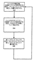
図2は、本発明の例示的な一つの実施の形態で左固有ベクトルを決定するためのフローチャートである。ステップ202では、通常動作期間に両方の駆動部が使用されて管路の振動が励起される。ステップ204では、駆動部D1だけが使用されて管路の振動が励起される。この期間に、駆動部D1で使用される駆動信号とセンサS1との間の位相が測定される。この測定位相差をθ1と呼ぶ。ステップ206では、駆動部D1が非活性化され、駆動部D2だけが使用されて管路の振動が励起される。この期間に、駆動部D2で使用される駆動信号とセンサS1との間の位相が測定される。この測定位相差をθ2と呼ぶ。ステップ208では、システムについての左固有ベクトルの相対位相θLをθL=θ1−θ2として計算することができる。時間領域に変換することにより、左固有ベクトルの相対的デルタTすなわちΔTL=(θ1−θ2)/ωが得られる。ステップ210では、通常動作が再開し、両方の駆動部が使用されて管路の振動が励起される。駆動部がオン及びオフされる順序は重要ではない。
FIG. 2 is a flowchart for determining a left eigenvector in an exemplary embodiment of the invention. In
1つの駆動部だけで管路の振動を励起するときに左固有ベクトルについての相対位相(θ1及びθ2)が決定されるので、残留柔軟性応答(RF)及び電磁気漏話(EC)を補正しなければならない。各駆動部は何らかの残留柔軟性応答及び電磁気漏話を引き起こす。この影響は駆動部が停止されたときにほぼ瞬時にゼロに減衰する。駆動部を短い期間だけ停止することにより、その駆動部に関連する残留柔軟性応答及び電磁気漏話によって引き起こされる各センサでの測定位相の変化を決定することができる。測定される位相の変化は、各駆動部が非活性化されたときに生じるセンサ間の差の階段状変化を測定することによって決定することができる。 Since the relative phase (θ1 and θ2) for the left eigenvector is determined when exciting the vibration of the pipeline with only one drive, the residual flexibility response (RF) and electromagnetic crosstalk (EC) must be corrected. Don't be. Each drive causes some residual flexibility response and electromagnetic crosstalk. This effect decays to zero almost instantaneously when the drive is stopped. By stopping the drive for a short period of time, it is possible to determine the change in measurement phase at each sensor caused by the residual flexible response and electromagnetic crosstalk associated with that drive. The measured phase change can be determined by measuring the step change in the difference between the sensors that occurs when each drive is deactivated.
図3は、残留柔軟性及び電子的漏話を決定するための一つの実施の形態を示すフローチャートである。ステップ302では、通常動作期間に両方の駆動部が使用されて管路の振動が励起される。両方の駆動部が動作する場合のデルタTであるΔTD1D2がセンサS1とセンサS1との間で測定される。ステップ304では駆動部D2が停止され、駆動部D1だけが使用されて管路が励起される。この期間に、駆動部D1だけが動作する場合のデルタTであるΔTD1がセンサS1とセンサS1の間で測定される。ΔTD1D2とΔTD1の差は、駆動部D2の残留柔軟性及び電子的漏話に起因する。ステップ306では、駆動部D1が停止され、駆動部D2だけが使用されて管路が励起される。この期間に、駆動部D2だけが動作する場合のデルタTであるΔTD2がセンサS1とセンサS1の間で測定される。ΔTD1D2とΔTD2の差は、駆動部D1の残留柔軟性及び電子的漏話に起因する。測定されたΔTを両方の駆動部の残留柔軟性及び電子的漏話に対して補正するために、測定されたΔTから、ΔTD1D2とΔTD1の差、及びΔTD1D2とΔTD2の差が差し引かれる。したがって、補正されたデルタTはΔTC=ΔT−(ΔTD1D2−ΔTD1)−(ΔTD1D2−ΔTD2)である。この技法を使用して、左固有ベクトルの相対位相についてのデルタTであるΔTLCを残留柔軟性及び電子的漏話について補正することができる。すなわち、ΔTLC=ΔTL−(ΔTD2−ΔTD1)。
FIG. 3 is a flowchart illustrating one embodiment for determining residual flexibility and electronic crosstalk. In
図4は、本発明の例示的な一つの実施の形態において駆動部を切り換えながら不平衡な単一管の流量計を使用して測定された相対的ΔT値を示すチャートである。この流量計では、駆動部DR1及びDR2が垂直方向から45度の向きにあり、センサPR3と同じ軸位置に位置する。DR1及びDR2を同じ信号で駆動することにより、擬似並置駆動部/センサ対が達成される。駆動部DL1、DL2及びセンサPL3を使用して擬似並置駆動部/センサ対を得るのに同じ関係が使用される。2つの駆動部センサ対(DR1/DR2/PR3及びDL1/DL2/PL3)は、流量計の軸中心の周りに対称に離間する。時刻ゼロから時刻30まで、両方の擬似駆動部対が使用されて流量計の振動が励起された。約30秒地点で、DL1/DL2駆動部対がオフにされるとき、ΔT値の階段状変化が生じる。このΔTの変化は、DL1/DL2擬似駆動部の残留柔軟性応答及び電磁気漏話によって引き起こされたものである。時刻約65で、駆動部対DR1/DR2がスイッチ・オフされ、駆動部対DL1/DL2がスイッチ・オンされる。ほぼ100秒の標識のところで、DR1/DR2駆動部対が再びオンとなり、両方の擬似駆動部対が使用されて流量計の振動が励起される。測定されたΔT値の時刻100から120の間の変化は、DR1/DR2擬似駆動部の残留柔軟性応答及び電磁気漏話によって引き起こされたものである。
FIG. 4 is a chart showing the relative ΔT values measured using an unbalanced single tube flow meter while switching the drive in one exemplary embodiment of the present invention. In this flow meter, the drive units DR1 and DR2 are oriented at 45 degrees from the vertical direction and are located at the same axial position as the sensor PR3. By driving DR1 and DR2 with the same signal, a pseudo juxtaposed drive / sensor pair is achieved. The same relationship is used to obtain a pseudo juxtaposed driver / sensor pair using the drivers DL1, DL2 and sensor PL3. Two driver sensor pairs (DR1 / DR2 / PR3 and DL1 / DL2 / PL3) are symmetrically spaced about the axial center of the flow meter. From time zero to time 30, both pseudo-drive pairs were used to excite the flow meter vibration. At about 30 seconds, when the DL1 / DL2 driver pair is turned off, a step change in ΔT value occurs. This change in ΔT is caused by the residual flexible response and electromagnetic crosstalk of the DL1 / DL2 pseudo drive unit. At about time 65, the drive unit pair DR1 / DR2 is switched off, and the drive unit pair DL1 / DL2 is switched on. At approximately 100 seconds, the DR1 / DR2 drive pair is turned on again, and both simulated drive pairs are used to excite the flow meter vibration. The change in the measured ΔT value between
駆動部及びセンサが流量計の軸中心の周りに対称に位置する流量計では、各駆動部に関連する残留柔軟性及び電子的漏話は、大きさが等しく、符号が逆である。通常動作期間に両方の駆動部が使用されて管路の振動が励起されるとき、各影響は打ち消し合い、右固有ベクトルのデルタTを正確に測定するために補正する必要がない。各駆動部が短い期間だけスイッチ・オフされるとき、同時に、左固有ベクトル及び残留柔軟性及び電子的漏話についての測定を行うことができる。 In flowmeters where the drive and sensor are located symmetrically about the axis center of the flowmeter, the residual flexibility and electronic crosstalk associated with each drive are equal in magnitude and opposite in sign. When both drives are used during normal operation to excite vibrations in the pipeline, each effect cancels out and does not need to be corrected to accurately measure the delta T of the right eigenvector. As each drive is switched off for a short period of time, measurements on the left eigenvector and residual flexibility and electronic crosstalk can be made simultaneously.
異なる電子測定チャネル間の不均一な位相を補償することは当技術分野で周知である。例えば、既知の信号を入力に印加し、位相の崩れを測定することができる。この手順は、テストの実施中にテスト中のチャネルの測定機能を引き受ける予備測定チャネルを設けることにより、流動期間に実施することができる。 Compensating for non-uniform phase between different electronic measurement channels is well known in the art. For example, a known signal can be applied to the input and phase collapse can be measured. This procedure can be performed during the flow period by providing a preliminary measurement channel that assumes the measurement function of the channel under test during the test.
左固有ベクトルと右固有ベクトルについての相対的ΔTが測定され、残留柔軟性、電子的漏話効果などについて補正された後、流れの寄与と非比例減衰の寄与が計算される。流れの影響Fは、左固有ベクトルと右固有ベクトルの相対的ΔT間の差を2で割ったものである。つまりF=(ΔTR−ΔTL)/2である。流れの影響Fを、通常動作期間にΔTRを測定することによって決定された流量と比較することによって、新しいゼロ・オフセットを計算することができる。すなわち、ZeroOffset=ΔTR−F。この新しいZeroOffsetを使用して、左固有ベクトルについての値が次回に決定されるまで、通常動作期間に測定流量を補正することができる。 After the relative ΔT for the left and right eigenvectors is measured and corrected for residual flexibility, electronic crosstalk effects, etc., the flow contribution and the non-proportional decay contribution are calculated. The flow effect F is the difference between the relative ΔT of the left and right eigenvectors divided by two. That is, F = (ΔT R −ΔT L ) / 2. The flow effect F, by comparing the flow rate determined by measuring the [Delta] T R to the normal operation period, it is possible to calculate the new zero offset. That is, ZeroOffset = ΔT R −F. This new ZeroOffset can be used to correct the measured flow rate during normal operation until the value for the left eigenvector is next determined.
非比例減衰効果NDは、左固有ベクトルと右固有ベクトルとの平均である。すなわち、ND=ΔTR+ΔTL)/2。この値を新しいZeroOffset値として使用することもできる。 The non-proportional damping effect ND is an average of the left eigenvector and the right eigenvector. That is, ND = ΔT R + ΔT L ) / 2. This value can also be used as a new ZeroOffset value.
図5は、本発明の例示的な一つの実施の形態において流動期間に流量計のゼロ・オフセットを再較正するためのフローチャートである。ステップ502では、通常動作期間に両方の駆動部が使用されて管路の振動が励起される。右固有ベクトルについての未補正の相対的デルタTが決定される。次いで、右固有ベクトルの未補正の相対的デルタTが、ゼロ・オフセットを使用することによって補正される。右固有ベクトルの補正された相対的デルタTを使用して、流量計を流れる流量が決定される。周期的に、ステップ504で駆動部D1及びD2が交互にスイッチ・オフされ、左固有ベクトルの相対的デルタT及び残留柔軟性(RF)及び電子的漏話(EC)が決定される。左固有ベクトルの相対的デルタTが残留柔軟性及び電子的漏話効果について補正される。ステップ506では、左固有ベクトルの補正された相対的デルタTと右固有ベクトルの未補正デルタTとが使用されて、新しいゼロ・オフセットが決定される。古いゼロ・オフセットが新しいゼロ・オフセットで置き換えられ、プロセスはステップ502で再開する。流量計の新しいゼロ・オフセットを計算し、それに置き換えることにより、流量計を通る材料の流動中の流量ゼロ条件について流量計が再較正される。
FIG. 5 is a flow chart for recalibrating the zero offset of the flow meter during the flow period in an exemplary embodiment of the invention. In
例示的な一つの実施の形態においては、いつ再較正を行うべきかについての決定は、較正と較正との間の一定の時間間隔を使用することによって行うことができる。別の例示的な実施の形態では、環境又は配管システムの変化が検出されたときに再較正を行うことができる。例えば、温度変化が閾量よりも大きいとき、再較正を実施することができる。再較正を行うときについての決定は、周期的タイマと環境変化の検出との組合せでよい。再較正と再較正との間の期間は、精度要件が低いシステムより、高い精度を必要とするシステムの方が短くてよい。 In one exemplary embodiment, the determination of when to recalibrate can be made by using a fixed time interval between calibrations. In another exemplary embodiment, recalibration can be performed when a change in the environment or piping system is detected. For example, recalibration can be performed when the temperature change is greater than a threshold amount. The decision about when to recalibrate may be a combination of a periodic timer and environmental change detection. The period between recalibrations may be shorter for systems that require high accuracy than systems with low accuracy requirements.
左固有ベクトルの相対位相を測定するための駆動部D1とD2の切り換えは、流量計の通常動作を中断しなければならないこと(すなわち、右固有ベクトルのΔTを使用して流量を測定すること)を意味するわけではない。例えば、駆動部が管路のセンターラインについて対称に配置されたとき、各駆動部は同じ量で駆動モードを励起する。例えばD1が非活性化されるときにD2への電流を2倍にすることにより、駆動力の大きさを維持することができる。 Switching between the drives D1 and D2 to measure the relative phase of the left eigenvector means that the normal operation of the flowmeter must be interrupted (ie, measuring the flow using the right eigenvector ΔT). Not to do. For example, when the drive units are arranged symmetrically about the center line of the pipeline, each drive unit excites the drive mode by the same amount. For example, the magnitude of the driving force can be maintained by doubling the current to D2 when D1 is deactivated.
上記の説明では、単一管路の流量計を使用して本発明を説明した。当技術分野で良く理解されているように、他の構成の流量計、例えば二重管路流量計で本発明を使用することができる。更に、直線管路を使用して本発明を説明したが、流量計の幾何形状について他の構成、例えば曲がった管路も可能である。 In the above description, the present invention has been described using a single-line flow meter. As is well understood in the art, the present invention can be used with other configurations of flow meters, such as double line flow meters. Furthermore, although the present invention has been described using a straight line, other configurations for the geometry of the flow meter, such as a curved line, are possible.
Claims (30)
振動管路の相対運動を測定するステップと、
前記管路についての左固有ベクトルの相対位相を周期的に決定するステップ(208)と、
を含む方法。 Flowing material through the conduit during excitation of the vibration mode of the conduit;
Measuring the relative motion of the vibrating conduit;
Periodically determining (208) the relative phase of the left eigenvector for the conduit;
Including methods.
前記左固有ベクトルの前記相対位相と前記右固有ベクトルの前記相対位相とを使用して、前記管路を通る前記材料の実際の流量を決定するステップと、
を更に含む、請求項1に記載の方法。 Determining the relative phase of the right eigenvector for the conduit (302);
Using the relative phase of the left eigenvector and the relative phase of the right eigenvector to determine an actual flow rate of the material through the conduit;
The method of claim 1, further comprising:
前記未補正流量を前記実際の流量と比較することにより、前記管路を通る前記材料の流量についてのゼロ・オフセットを決定するステップ(506)と、
を更に含む、請求項2に記載の方法。 Using the relative phase of the right eigenvector to determine an uncorrected flow rate of the material flowing through the conduit;
Determining (506) a zero offset for the flow rate of the material through the conduit by comparing the uncorrected flow rate with the actual flow rate;
The method of claim 2 further comprising:
前記右固有ベクトルの前記相対位相と前記左固有ベクトルの前記相対位相との平均を取ることにより、前記管路を通る前記材料の流量についてのゼロ・オフセットを決定するステップと、
を更に含む、請求項1に記載の方法。 Determining the relative phase of the right eigenvector;
Determining a zero offset for the flow rate of the material through the conduit by averaging the relative phase of the right eigenvector and the relative phase of the left eigenvector;
The method of claim 1, further comprising:
第1駆動部(304)と該第1駆動部から離間した第2駆動部とを使用して前記管路の前記振動モードを励起している間に、前記振動管路上の2つの離間した位置の間の第1相対位相を測定するステップと、
前記第2駆動部だけを使用して前記管路の前記振動モードを励起している間に、前記振動管路上の前記2つの離間した位置間の第2相対位相を測定するステップ(304)と、
前記第1相対位相から前記第2相対位相を差し引くことにより、前記第1駆動部に関連する残留柔軟性応答及び電磁気的漏話を計算するステップ(308)と、
第1駆動部だけを使用して前記管路の前記振動モードを励起している間に、前記振動管路上の前記2つの離間した位置間の第3相対位相を測定するステップ(306)と、
前記第1相対位相から前記第3相対位相を差し引くことにより、前記第2駆動部に関連する残留柔軟性応答及び電磁気的漏話を計算するステップ(308)と、
を更に含む、請求項7に記載の方法。 In addition,
Two excited positions on the vibrating conduit while exciting the vibration mode of the conduit using the first driver (304) and a second driver spaced apart from the first driver. Measuring a first relative phase between:
Measuring a second relative phase between the two spaced locations on the vibrating conduit while exciting the vibration mode of the conduit using only the second driver; and ,
Calculating a residual flexibility response and electromagnetic crosstalk associated with the first driver by subtracting the second relative phase from the first relative phase;
Measuring a third relative phase between the two spaced locations on the vibrating conduit while exciting the vibration mode of the conduit using only the first drive (306);
Calculating a residual flexibility response and electromagnetic crosstalk associated with the second driver by subtracting the third relative phase from the first relative phase (308);
The method of claim 7, further comprising:
前記振動管路の運動を測定するステップと、
前記駆動部のうちの第1の駆動部だけを使用して前記管路の前記振動モードを駆動している間に、前記管路上の第1位置と前記駆動部のうちの前記第1の駆動部との間の第1位置関係を決定するステップ(204)と、
前記駆動部のうちの第2の駆動部だけを使用して前記管路の前記振動モードを駆動している間に、前記管路上の前記第1位置と前記駆動部のうちの前記第2の駆動部との間の第2位置関係を決定するステップ(206)と、
前記第1位置関係及び前記第2位置関係を使用して左固有ベクトルを決定するステップ(208)と、
を含む方法。 Flowing material through the conduit while exciting the vibration mode of the conduit using at least two drives in a spaced configuration;
Measuring the motion of the vibrating line;
While driving the vibration mode of the pipeline using only the first drive unit of the drive unit, the first position of the pipeline and the first drive of the drive unit Determining a first positional relationship with the unit (204);
While driving the vibration mode of the pipeline using only the second drive unit of the drive unit, the first position on the pipeline and the second of the drive units. Determining a second positional relationship with the drive unit (206);
Determining a left eigenvector using the first positional relationship and the second positional relationship (208);
Including methods.
前記右固有ベクトルの前記相対位相から前記左固有ベクトルの前記相対位相を差し引くことにより、前記管路を通る前記材料の実際の流量を決定するステップと、
を更に含む、請求項9に記載の方法。 Determining the relative phase of the right eigenvector for the conduit while exciting the vibration mode of the conduit using the first driver and the second driver;
Determining the actual flow rate of the material through the conduit by subtracting the relative phase of the left eigenvector from the relative phase of the right eigenvector;
The method of claim 9, further comprising:
前記未補正流量を前記実際の流量と比較することにより、前記管路を通る材料の流量についてのゼロ・オフセットを決定するステップと、
前記ゼロ・オフセットで補正された前記右固有ベクトルの前記相対位相を使用して、前記管路を流れる材料流量を決定するステップと、
を更に含む、請求項11に記載の方法。 Using the relative phase of the right eigenvector to determine an uncorrected flow rate of the material flowing through the conduit;
Determining a zero offset for the flow rate of material through the conduit by comparing the uncorrected flow rate with the actual flow rate;
Using the relative phase of the right eigenvector corrected for the zero offset to determine a material flow rate through the conduit;
The method of claim 11, further comprising:
前記右固有ベクトルの前記相対位相と前記左固有ベクトルの前記相対位相との平均を取ることにより、前記管路を通る前記材料の流量についてのゼロ・オフセットを決定するステップと、
前記ゼロ・オフセットで補正された前記右固有ベクトルの前記相対位相を使用して、前記管路を流れる材料流量を決定するステップと、
を更に含む、請求項9に記載の方法。 Determining the relative phase of the right eigenvector for the conduit while exciting the vibration mode of the conduit using the first driver and the second driver;
Determining a zero offset for the flow rate of the material through the conduit by averaging the relative phase of the right eigenvector and the relative phase of the left eigenvector;
Using the relative phase of the right eigenvector corrected for the zero offset to determine a material flow rate through the conduit;
The method of claim 9, further comprising:
前記駆動部のうちの第1の駆動部を除くすべての駆動部を使用して前記振動モードを駆動するときに、前記第1位置と前記第2位置との間の第2デルタ時間を測定するステップ(304)と、
前記駆動部のうちの第2の駆動部を除くすべての駆動部を使用して前記振動モードを駆動するときに、前記第1位置と前記第2位置との間の第3デルタ時間を測定するステップ(306)と、
前記第1デルタ時間及び前記第2デルタ時間を使用して第1補正値を計算するステップ(308)と、
前記第1デルタ時間及び前記第3デルタ時間を使用して第2補正値を計算するステップ(308)と、
前記左固有ベクトルを計算する前に、前記第1補正値を使用して前記第1位置関係を調節するステップと、
前記左固有ベクトルを計算する前に、前記第2補正値を使用して前記第2位置関係を調節するステップと、
を更に含む、請求項9に記載の方法。 Measuring a first delta time between the first position and the second position when driving the vibration mode using at least two drives;
A second delta time between the first position and the second position is measured when the vibration mode is driven using all of the driving units except the first driving unit. Step (304);
A third delta time between the first position and the second position is measured when the vibration mode is driven using all of the driving parts except the second driving part. Step (306);
Calculating a first correction value using the first delta time and the second delta time (308);
Calculating a second correction value using the first delta time and the third delta time (308);
Adjusting the first positional relationship using the first correction value before calculating the left eigenvector;
Adjusting the second positional relationship using the second correction value before calculating the left eigenvector;
The method of claim 9, further comprising:
前記振動管路の相対運動を測定するステップと、
前記管路の前記振動モードを励起中に、前記右固有ベクトルの前記相対位相を測定するステップと、
ゼロ・オフセットで補正された前記右固有ベクトルの前記相対位相を使用して、前記管路を流れる材料流量を決定するステップ(502)と、
前記管路を流れる材料の流れを停止させることなく、新しいゼロ・オフセットを決定するステップと、
前記新しいゼロ・オフセットで補正された前記右固有ベクトルの前記相対位相を使用して、前記管路を流れる材料流量を決定するステップと、
を含む方法。 Flowing material through the conduit during excitation of the vibration mode of the conduit;
Measuring the relative movement of the vibrating conduit;
Measuring the relative phase of the right eigenvector while exciting the vibration mode of the conduit;
Using the relative phase of the right eigenvector corrected with zero offset to determine a material flow through the conduit (502);
Determining a new zero offset without stopping the flow of material through the conduit;
Using the relative phase of the right eigenvector corrected with the new zero offset to determine a material flow rate through the conduit;
Including methods.
前記管路の複数の振動モードを励起するように構成された少なくとも2つの駆動部(D1、D2)と、
前記振動管路の相対運動を測定するように構成された検出装置と、
前記振動管路の相対運動を使用して、前記管路についての左固有ベクトルの相対位相を周期的に決定するように構成された装置であって、前記振動管路の相対運動を使用して、前記管路についての右固有ベクトルの相対位相を決定するようにも構成された装置と、
を備える機器。 A conduit (102) configured to contain flowing material;
At least two drivers (D1, D2) configured to excite a plurality of vibration modes of the conduit;
A detection device configured to measure relative motion of the vibrating conduit;
An apparatus configured to periodically determine the relative phase of a left eigenvector for the pipe using the relative movement of the vibrating pipe, using the relative movement of the vibrating pipe, An apparatus configured to determine a relative phase of a right eigenvector for the conduit;
Equipment with.
前記右固有ベクトルの前記相対位相を使用して決定された前記流量を前記実際の流量と比較することにより、前記管路を通る材料の流量についての前記ゼロ・オフセットが決定される、
請求項22に記載の機器。 By subtracting the relative phase of the left eigenvector from the relative phase of the right eigenvector, the actual flow rate of the material through the conduit is determined,
By comparing the flow rate determined using the relative phase of the right eigenvector with the actual flow rate, the zero offset for the flow rate of material through the conduit is determined;
The device according to claim 22.
前記少なくとも2つの駆動部のうちの第1の駆動部を除くすべての駆動部を使用して前記管路の前記振動モードを励起する間に、前記振動管路上の前記第1位置と、前記振動管路上の前記第2位置との間の第2相対位相が決定され、
前記少なくとも2つの駆動部のうちの第2の駆動部を除くすべての駆動部を使用して前記管路の前記振動モードを励起する間に、前記振動管路上の前記第1位置と、前記振動管路上の前記第2位置との間の第3相対位相が決定され、
前記第1相対位相から前記第2相対位相を差し引くことにより、前記少なくとも2つの駆動部の前記第1の駆動部についての残留柔軟性応答及び電磁気漏話が決定され、
前記第1相対位相から前記第3相対位相を差し引くことにより、前記少なくとも2つの駆動部の前記第2の駆動部についての残留柔軟性応答及び電磁気漏話が決定される、
請求項25に記載の機器。 A first relative between a first position on the vibrating conduit and a second position on the vibrating conduit while exciting the vibration mode of the conduit using the at least two drives. The phase is determined,
The first position on the vibrating pipeline and the vibration during excitation of the vibration mode of the pipeline using all of the at least two drivers except for the first driver. A second relative phase with respect to the second position on the pipeline is determined;
The first position on the oscillating pipeline and the vibration during excitation of the oscillating mode of the pipeline using all of the at least two drivers except for the second driver. A third relative phase with respect to the second position on the pipeline is determined;
By subtracting the second relative phase from the first relative phase, a residual flexibility response and electromagnetic crosstalk for the first drive of the at least two drives is determined,
By subtracting the third relative phase from the first relative phase, a residual flexibility response and electromagnetic crosstalk for the second drive of the at least two drives is determined.
The device according to claim 25.
前記管路の振動モードを励起する手段と、
前記振動管路の相対運動を検知する手段と、
前記管路についての左固有ベクトルの相対位相を周期的に決定する手段と、
前記管路についての前記右固有ベクトルの前記相対位相を決定する手段と、
前記右固有ベクトルの前記相対位相と前記左固有ベクトルの前記相対位相との平均を取ることにより、前記管路を流れる前記材料についてのゼロ・オフセットを決定する手段と、
前記ゼロ・オフセットで補正された前記右固有ベクトルの前記相対位相を使用することによって実際の材料流量を決定する手段と、
を備える機器。 A conduit (102) configured to contain material flowing through the conduit;
Means for exciting the vibration mode of the conduit;
Means for detecting relative movement of the vibrating conduit;
Means for periodically determining the relative phase of the left eigenvector for the conduit;
Means for determining the relative phase of the right eigenvector for the conduit;
Means for determining a zero offset for the material flowing through the conduit by averaging the relative phase of the right eigenvector and the relative phase of the left eigenvector;
Means for determining an actual material flow rate by using the relative phase of the right eigenvector corrected for the zero offset;
Equipment with.
Applications Claiming Priority (1)
| Application Number | Priority Date | Filing Date | Title |
|---|---|---|---|
| PCT/US2004/031549 WO2006036139A1 (en) | 2004-09-27 | 2004-09-27 | In-flow determination of left and right eigenvectors in a coriolis flowmeter |
Related Child Applications (1)
| Application Number | Title | Priority Date | Filing Date |
|---|---|---|---|
| JP2012001393A Division JP2012098301A (en) | 2012-01-06 | 2012-01-06 | Determination of inflow of right and left characteristic vectors in coriolis flowmeter |
Publications (2)
| Publication Number | Publication Date |
|---|---|
| JP2008514916A true JP2008514916A (en) | 2008-05-08 |
| JP2008514916A5 JP2008514916A5 (en) | 2011-02-24 |
Family
ID=34958795
Family Applications (1)
| Application Number | Title | Priority Date | Filing Date |
|---|---|---|---|
| JP2007533443A Pending JP2008514916A (en) | 2004-09-27 | 2004-09-27 | Determination of the inflow of the right and left eigenvectors in a Coriolis flowmeter |
Country Status (11)
| Country | Link |
|---|---|
| US (1) | US7706987B2 (en) |
| EP (2) | EP2120020B1 (en) |
| JP (1) | JP2008514916A (en) |
| KR (1) | KR100973772B1 (en) |
| CN (1) | CN100458377C (en) |
| AR (1) | AR051036A1 (en) |
| BR (1) | BRPI0419040B1 (en) |
| CA (1) | CA2581107C (en) |
| HK (1) | HK1111760A1 (en) |
| MX (1) | MX2007003176A (en) |
| WO (1) | WO2006036139A1 (en) |
Cited By (2)
| Publication number | Priority date | Publication date | Assignee | Title |
|---|---|---|---|---|
| JP2018522244A (en) * | 2015-07-27 | 2018-08-09 | マイクロ モーション インコーポレイテッド | Off-resonance cycling of Coriolis flow meters |
| JP2018526627A (en) * | 2015-07-27 | 2018-09-13 | マイクロ モーション インコーポレイテッド | Method for obtaining the left eigenvector of a Coriolis flow meter through which fluid flows |
Families Citing this family (17)
| Publication number | Priority date | Publication date | Assignee | Title |
|---|---|---|---|---|
| DE102006044592A1 (en) | 2006-09-19 | 2008-03-27 | Endress + Hauser Flowtec Ag | Method for determining the mass flow rate of a Coriolis mass flowmeter arranged on a rotary filler |
| DE102007024276A1 (en) | 2007-05-23 | 2008-11-27 | Endress + Hauser Flowtec Ag | Method for measuring and monitoring flow parameter of medium, involves exciting measuring tube to mechanical vibrations by one converter element according to one excitation signal during one measurement |
| DE102007024275A1 (en) | 2007-05-23 | 2008-11-27 | Endress + Hauser Flowtec Ag | Method for measuring and / or monitoring a flow parameter and corresponding device |
| DE102007028209A1 (en) * | 2007-06-15 | 2008-12-18 | Endress + Hauser Flowtec Ag | Method for measuring and / or monitoring a flow parameter and corresponding device |
| JP5589351B2 (en) * | 2009-11-02 | 2014-09-17 | パナソニック株式会社 | Flow measuring device |
| DE102010006224A1 (en) * | 2010-01-28 | 2011-08-18 | Krohne Ag | Method for determining a parameter for the correction of measured values of a Coriolis mass flowmeter |
| DE202010009023U1 (en) * | 2010-06-12 | 2011-11-14 | Neoperl Gmbh | aerator |
| AU2011379966B2 (en) | 2011-10-26 | 2015-01-29 | Micro Motion, Inc. | Collocated sensor for a vibrating fluid meter |
| EP3008428B1 (en) | 2013-06-14 | 2021-02-24 | Micro Motion, Inc. | Vibratory flowmeter and method for meter verification |
| BR112016016581B1 (en) * | 2014-01-24 | 2021-03-02 | Micro Motion, Inc | vibratory flow meter for meter verification, and meter verification method |
| DE102015107366B3 (en) * | 2015-05-11 | 2016-01-21 | Krohne Messtechnik Gmbh | Method of operating a flowmeter and related flowmeter |
| WO2017146717A1 (en) * | 2016-02-26 | 2017-08-31 | Micro Motion, Inc. | Determining a corrected measured flow rate |
| US11402254B2 (en) * | 2019-08-13 | 2022-08-02 | Badger Meter, Inc. | Ultrasonic flow meter calibration system and method |
| DE112021003296A5 (en) | 2020-06-18 | 2023-05-11 | Endress+Hauser Flowtec Ag | Vibronic measuring system |
| DE102020131649A1 (en) | 2020-09-03 | 2022-03-03 | Endress + Hauser Flowtec Ag | Vibronic measuring system |
| DE102020134707A1 (en) | 2020-12-22 | 2022-06-23 | Endress+Hauser Flowtec Ag | Coriolis mass flow meter and method for determining factors influencing its total zero error, method for determining total zero error and operating method therefor |
| CN113188637B (en) * | 2021-04-30 | 2022-02-15 | 南京荣晟自动化设备有限公司 | Movable on-line calibrating device for coriolis mass flowmeter by standard meter method |
Family Cites Families (19)
| Publication number | Priority date | Publication date | Assignee | Title |
|---|---|---|---|---|
| USRE31450E (en) | 1977-07-25 | 1983-11-29 | Micro Motion, Inc. | Method and structure for flow measurement |
| US4365154A (en) * | 1980-03-06 | 1982-12-21 | Texaco Inc. | Detection of impurities in a fluid containing free gas using nuclear techniques |
| US4491025A (en) | 1982-11-03 | 1985-01-01 | Micro Motion, Inc. | Parallel path Coriolis mass flow rate meter |
| US5373745A (en) | 1991-02-05 | 1994-12-20 | Direct Measurement Corporation | Single path radial mode Coriolis mass flow rate meter |
| JP3200826B2 (en) | 1993-11-19 | 2001-08-20 | 横河電機株式会社 | Coriolis mass flowmeter |
| US5734112A (en) | 1996-08-14 | 1998-03-31 | Micro Motion, Inc. | Method and apparatus for measuring pressure in a coriolis mass flowmeter |
| US6199022B1 (en) | 1997-07-11 | 2001-03-06 | Micro Motion, Inc. | Drive circuit modal filter for a vibrating tube flowmeter |
| US6092429A (en) | 1997-12-04 | 2000-07-25 | Micro Motion, Inc. | Driver for oscillating a vibrating conduit |
| US6360175B1 (en) | 1998-02-25 | 2002-03-19 | Micro Motion, Inc. | Generalized modal space drive control system for a vibrating tube process parameter sensor |
| US5987999A (en) | 1998-07-01 | 1999-11-23 | Micro Motion, Inc. | Sensitivity enhancing balance bar |
| US6233526B1 (en) | 1998-07-16 | 2001-05-15 | Micro Motion, Inc. | Vibrating conduit parameter sensors and methods of operation therefor utilizing spatial integration |
| US6427127B1 (en) * | 1998-07-16 | 2002-07-30 | Micro Motion, Inc. | Vibrating conduit process parameter sensors, operating methods and computer program products utilizing complex modal estimation |
| US6272438B1 (en) * | 1998-08-05 | 2001-08-07 | Micro Motion, Inc. | Vibrating conduit parameter sensors, methods and computer program products for generating residual-flexibility-compensated mass flow estimates |
| US6577977B2 (en) | 1999-02-16 | 2003-06-10 | Micro Motion, Inc. | Process parameter sensor apparatus, methods and computer program products using force filtering |
| GB2350426B (en) * | 1999-05-25 | 2002-08-28 | Abb Instrumentation Ltd | Vibrating tube meter |
| US6347293B1 (en) | 1999-07-09 | 2002-02-12 | Micro Motion, Inc. | Self-characterizing vibrating conduit parameter sensors and methods of operation therefor |
| US6466880B2 (en) * | 2001-02-16 | 2002-10-15 | Micro Motion, Inc. | Mass flow measurement methods, apparatus, and computer program products using mode selective filtering |
| US6606573B2 (en) | 2001-08-29 | 2003-08-12 | Micro Motion, Inc. | Sensor apparatus, methods and computer program products employing vibrational shape control |
| US6704666B2 (en) * | 2001-08-29 | 2004-03-09 | Micro Motion, Inc. | Determining properties of a flow tube and of a fluid flowing through a flow tube of a coriolis flowmeter |
-
2004
- 2004-09-27 CN CNB2004800440862A patent/CN100458377C/en active Active
- 2004-09-27 EP EP08170888.5A patent/EP2120020B1/en active Active
- 2004-09-27 BR BRPI0419040A patent/BRPI0419040B1/en active IP Right Grant
- 2004-09-27 EP EP04785069.8A patent/EP1794549B1/en active Active
- 2004-09-27 US US11/574,716 patent/US7706987B2/en active Active
- 2004-09-27 MX MX2007003176A patent/MX2007003176A/en active IP Right Grant
- 2004-09-27 JP JP2007533443A patent/JP2008514916A/en active Pending
- 2004-09-27 WO PCT/US2004/031549 patent/WO2006036139A1/en active Application Filing
- 2004-09-27 CA CA2581107A patent/CA2581107C/en active Active
- 2004-09-27 KR KR1020077009504A patent/KR100973772B1/en active IP Right Grant
-
2005
- 2005-09-26 AR ARP050104019A patent/AR051036A1/en unknown
-
2008
- 2008-03-06 HK HK08102644.8A patent/HK1111760A1/en unknown
Cited By (2)
| Publication number | Priority date | Publication date | Assignee | Title |
|---|---|---|---|---|
| JP2018522244A (en) * | 2015-07-27 | 2018-08-09 | マイクロ モーション インコーポレイテッド | Off-resonance cycling of Coriolis flow meters |
| JP2018526627A (en) * | 2015-07-27 | 2018-09-13 | マイクロ モーション インコーポレイテッド | Method for obtaining the left eigenvector of a Coriolis flow meter through which fluid flows |
Also Published As
| Publication number | Publication date |
|---|---|
| AR051036A1 (en) | 2006-12-13 |
| CN100458377C (en) | 2009-02-04 |
| BRPI0419040B1 (en) | 2016-06-28 |
| US20080011100A1 (en) | 2008-01-17 |
| EP2120020B1 (en) | 2019-12-25 |
| EP2120020A1 (en) | 2009-11-18 |
| MX2007003176A (en) | 2007-06-05 |
| HK1111760A1 (en) | 2008-08-15 |
| CA2581107A1 (en) | 2006-04-06 |
| CA2581107C (en) | 2013-01-08 |
| KR20070049253A (en) | 2007-05-10 |
| CN101036037A (en) | 2007-09-12 |
| WO2006036139A1 (en) | 2006-04-06 |
| EP1794549A1 (en) | 2007-06-13 |
| US7706987B2 (en) | 2010-04-27 |
| KR100973772B1 (en) | 2010-08-04 |
| BRPI0419040A (en) | 2007-12-11 |
| EP1794549B1 (en) | 2019-03-27 |
Similar Documents
| Publication | Publication Date | Title |
|---|---|---|
| JP2008514916A (en) | Determination of the inflow of the right and left eigenvectors in a Coriolis flowmeter | |
| JP2008514916A5 (en) | ||
| JP4469337B2 (en) | Coriolis flow meter diagnostic device and diagnostic method | |
| JP4690865B2 (en) | Mass flow meter control method | |
| JP4331599B2 (en) | Calibration of Coriolis mass flowmeters using normal mode analysis | |
| US10890473B2 (en) | Off-resonance cycling for coriolis flowmeters | |
| JP5144266B2 (en) | Method and apparatus for measuring flow rate in a pipeline by measuring Coriolis coupling between two vibration modes | |
| US7523005B2 (en) | Clamp-on coriolis mass flow meter using in-situ calibration | |
| JP5836427B2 (en) | Determination of the inflow of the right and left eigenvectors in a Coriolis flowmeter | |
| JP7049527B2 (en) | Determining the damping characteristics of the meter assembly | |
| JP2012098301A (en) | Determination of inflow of right and left characteristic vectors in coriolis flowmeter | |
| RU2369840C2 (en) | Identification of left and right internal vectors in coriolis flow metre in mode with flow | |
| JP7206368B2 (en) | Electronic measuring instrument and verification diagnostic method for flow meter | |
| WO2023191762A1 (en) | Mode excitation detection for a vibratory flowmeter and related methods | |
| JP2011128167A (en) | Method and apparatus for measuring flow through conduit by measuring coriolis coupling between two vibration modes |
Legal Events
| Date | Code | Title | Description |
|---|---|---|---|
| A977 | Report on retrieval |
Free format text: JAPANESE INTERMEDIATE CODE: A971007 Effective date: 20100625 |
|
| A131 | Notification of reasons for refusal |
Free format text: JAPANESE INTERMEDIATE CODE: A131 Effective date: 20100927 |
|
| A524 | Written submission of copy of amendment under section 19 (pct) |
Free format text: JAPANESE INTERMEDIATE CODE: A524 Effective date: 20101227 |
|
| A02 | Decision of refusal |
Free format text: JAPANESE INTERMEDIATE CODE: A02 Effective date: 20110908 |
|
| RD04 | Notification of resignation of power of attorney |
Free format text: JAPANESE INTERMEDIATE CODE: A7424 Effective date: 20110913 |
|
| A521 | Written amendment |
Free format text: JAPANESE INTERMEDIATE CODE: A523 Effective date: 20120106 |
|
| A911 | Transfer to examiner for re-examination before appeal (zenchi) |
Free format text: JAPANESE INTERMEDIATE CODE: A911 Effective date: 20120116 |
|
| A912 | Re-examination (zenchi) completed and case transferred to appeal board |
Free format text: JAPANESE INTERMEDIATE CODE: A912 Effective date: 20120921 |
|
| A601 | Written request for extension of time |
Free format text: JAPANESE INTERMEDIATE CODE: A601 Effective date: 20130107 |
|
| A602 | Written permission of extension of time |
Free format text: JAPANESE INTERMEDIATE CODE: A602 Effective date: 20130110 |
|
| A521 | Written amendment |
Free format text: JAPANESE INTERMEDIATE CODE: A821 Effective date: 20130410 |
|
| A521 | Written amendment |
Free format text: JAPANESE INTERMEDIATE CODE: A523 Effective date: 20130905 |