JP2008514500A - "Electric vehicle power supply device via floor" - Google Patents
"Electric vehicle power supply device via floor" Download PDFInfo
- Publication number
- JP2008514500A JP2008514500A JP2007534043A JP2007534043A JP2008514500A JP 2008514500 A JP2008514500 A JP 2008514500A JP 2007534043 A JP2007534043 A JP 2007534043A JP 2007534043 A JP2007534043 A JP 2007534043A JP 2008514500 A JP2008514500 A JP 2008514500A
- Authority
- JP
- Japan
- Prior art keywords
- floor
- conductor
- supply
- mounted power
- current
- Prior art date
- Legal status (The legal status is an assumption and is not a legal conclusion. Google has not performed a legal analysis and makes no representation as to the accuracy of the status listed.)
- Granted
Links
Images


Classifications
-
- B—PERFORMING OPERATIONS; TRANSPORTING
- B60—VEHICLES IN GENERAL
- B60L—PROPULSION OF ELECTRICALLY-PROPELLED VEHICLES; SUPPLYING ELECTRIC POWER FOR AUXILIARY EQUIPMENT OF ELECTRICALLY-PROPELLED VEHICLES; ELECTRODYNAMIC BRAKE SYSTEMS FOR VEHICLES IN GENERAL; MAGNETIC SUSPENSION OR LEVITATION FOR VEHICLES; MONITORING OPERATING VARIABLES OF ELECTRICALLY-PROPELLED VEHICLES; ELECTRIC SAFETY DEVICES FOR ELECTRICALLY-PROPELLED VEHICLES
- B60L5/00—Current collectors for power supply lines of electrically-propelled vehicles
- B60L5/40—Current collectors for power supply lines of electrically-propelled vehicles for collecting current from lines in slotted conduits
-
- B—PERFORMING OPERATIONS; TRANSPORTING
- B60—VEHICLES IN GENERAL
- B60M—POWER SUPPLY LINES, AND DEVICES ALONG RAILS, FOR ELECTRICALLY- PROPELLED VEHICLES
- B60M1/00—Power supply lines for contact with collector on vehicle
- B60M1/30—Power rails
- B60M1/34—Power rails in slotted conduits
-
- B—PERFORMING OPERATIONS; TRANSPORTING
- B60—VEHICLES IN GENERAL
- B60L—PROPULSION OF ELECTRICALLY-PROPELLED VEHICLES; SUPPLYING ELECTRIC POWER FOR AUXILIARY EQUIPMENT OF ELECTRICALLY-PROPELLED VEHICLES; ELECTRODYNAMIC BRAKE SYSTEMS FOR VEHICLES IN GENERAL; MAGNETIC SUSPENSION OR LEVITATION FOR VEHICLES; MONITORING OPERATING VARIABLES OF ELECTRICALLY-PROPELLED VEHICLES; ELECTRIC SAFETY DEVICES FOR ELECTRICALLY-PROPELLED VEHICLES
- B60L2200/00—Type of vehicles
- B60L2200/26—Rail vehicles
Abstract
給電装置(1)に、少なくとも1本の供給電圧に接続される直線供給導体(7)、少なくとも1本のゼロボルト導体帰路(8)を支えるレール(6)ならびに直線導体を隠すことになる少なくとも1つの傾斜したL字状の保護断面(35)が含まれる床付け電流供給装置(2)が含まれる。これには電気的に車両の利用者回路ならびにゼロボルト帰路に接続されると同時に供給導体とそれぞれ滑り接触状態になるよう仕向けられる出力集電靴(41)ならびにゼロボルト集電靴(42)が含まれる少なくとも1つの移動通電構成部品(38)が含まれる電流通電の搭載装置(3)も含まれる。この発明は都市輸送車両ならびにこれらの車両用軌道の導体に利するものである。
【選択図】図1At least one linear supply conductor (7) connected to at least one supply voltage, a rail (6) supporting at least one zero volt conductor return path (8) and at least one linear conductor are hidden in the power supply device (1). A floor current supply device (2) is included which includes two inclined L-shaped protective cross sections (35). This includes an output current collector shoe (41) and a zero volt current collector shoe (42) that are electrically connected to the vehicle user circuit as well as the zero volt return path and are each brought into sliding contact with the supply conductor. Also included is a current-carrying mounting device (3) that includes at least one mobile energization component (38). The present invention is useful for city transport vehicles and conductors for these vehicle tracks.
[Selection] Figure 1
Description
本発明は好ましくは誘導レール上を走行する誘導装置により誘導される電動車両向け床経由給電装置に関する。 The present invention preferably relates to a power supply apparatus for passing through a floor for an electric vehicle guided by a guide device that travels on a guide rail.
本発明は特に直流低電圧の床経由給電装置を対象とする。 The present invention is particularly directed to a DC low voltage via-floor power feeder.
対象とする電動車両は例えば道路上の陸上車両であるが鉄道車両でも良い。 The target electric vehicle is, for example, a land vehicle on a road, but may be a rail vehicle.
本発明は特に電気推進力により自動誘導される都市公共輸送車両の給電に応用され、この車両は鉄道走行かあるいはタイヤ走行タイプであり得る。しかしながら、本発明はこのような好ましい用途だけに限定されるものではない。 The present invention is particularly applicable to power supply for city public transport vehicles that are automatically guided by electric propulsion, which vehicles can be of the rail type or of the tire type. However, the present invention is not limited to such preferred applications.
このタイプの電気推進力あるいは牽引力による車両は従来方法の空中ケーブルあるいはその交通軌道上部に配されるカテナリー吊り線により電気エネルギーが供給される。 Vehicles of this type of electric propulsion or traction are supplied with electrical energy by conventional methods of aerial cables or catenary suspension lines placed above the traffic track.
しかしながら、実際は審美的な理由あるいはその他で、これらの電化空中線が無くされる傾向になっているとともに、床面あるいは埋込みの給電装置に置き換えられるようになってきている。先行技術では様々な床付け給電装置がこれらの車両向けに提案された。しかしながら、これらの装置ではすべて安全に関していくつかの深刻な欠点が呈されている。実際、これらの先行装置では、特に導体部品と接触する場合に、人に極めて危険であることが明白である直流高電圧の給電が用意されている。しかも、高電圧の利用で浮遊電流の存在につながる余計な危険が生じている。 In practice, however, these electrified antennas tend to be eliminated for aesthetic reasons or otherwise, and replaced by floor or embedded feeders. In the prior art, various floor-mounted power feeders have been proposed for these vehicles. However, all these devices present some serious drawbacks with regard to safety. In fact, these predecessors provide DC high-voltage power supplies that are clearly dangerous for humans, especially when they come into contact with conductor parts. In addition, the use of high voltage creates an extra danger that leads to the presence of stray currents.
本発明の目的はその設置と配線が単純かつ迅速である電動車両向けの公共上完全に安全な床付け給電装置が提供されることにある。 An object of the present invention is to provide a publicly completely safe floor-mounted power feeding device for electric vehicles that is simple and quick to install and to wire.
本発明のもう一つの目的はメンテナンスの簡単な床付け給電装置の提供にある。 Another object of the present invention is to provide a floor-mounted power supply device that is easy to maintain.
この技術問題が解決されるため、本発明により、決められた軌道上を移動する少なくとも1本の導体部品との滑り接触による床付け給電タイプの陸上車両向け床付け給電装置が提供される。この装置には車両上に搭載されると同時に該車両と一緒に移動する床に設置される電流供給装置ならびに通電装置が含まれる。 In order to solve this technical problem, the present invention provides a floor-mounted power supply device for land vehicles of a floor-mounted power supply type by sliding contact with at least one conductor component moving on a predetermined track. This device includes a current supply device and a power supply device that are installed on the vehicle and installed on the floor that moves with the vehicle.
本発明による給電装置は上部が開いた溝内に配置される。これには給電電圧に接続される少なくとも1本の直線供給導体が含まれ、この少なくとも1本の導体は少なくとも1本のゼロボルト導体帰路を支持するレールの横方向溝内に設置される。これにはさらに下部に配置される直線導体を取り囲むと同時に隠すようになる傾斜したL字の全体形状を呈する少なくとも1つの保護断面が含まれる。 The power supply device according to the present invention is disposed in a groove having an open top. This includes at least one linear supply conductor connected to the supply voltage, the at least one conductor being placed in the lateral groove of the rail supporting at least one zero volt conductor return. This further includes at least one protective cross-section that exhibits the overall shape of an inclined L-shape that surrounds and conceals the straight conductors located below.
通電搭載装置にはレールの横方向溝内を走る支持架線装置により担われる少なくとも1つの移動通電構成部品が含まれる。この通電構成部品には、供給導体と電気的滑り接触状態になるよう仕向けられる出力集電靴ならびにゼロボルト導体帰路と電気的滑り接触状態になるよう仕向けられるゼロボルト集電靴が含まれ、これらの集電靴は車両の利用者回路に電気的に接続される。 The energization mounting device includes at least one moving energization component carried by a supporting overhead line device that runs in a lateral groove of the rail. This energizing component includes an output current collector shoe that is intended to be in electrical sliding contact with the supply conductor and a zero-volt current collector shoe that is intended to be in electrical sliding contact with the zero-volt conductor return path. The shoe is electrically connected to the user circuit of the vehicle.
出力集電靴と給電導体間の接触は保護断面の下で行われると同時にこの保護断面の折り返しにより取り囲まれるのが有利である。 Advantageously, the contact between the output current collector shoe and the feed conductor is made under the protective cross section and at the same time is surrounded by the folding of the protective cross section.
この少なくとも1本の直線給電導体は供給直流電圧に接続され得るのが好ましい。 This at least one linear feed conductor is preferably connectable to a supply DC voltage.
本発明による供給装置により完全な安全が歩行者あるいは本線のその他利用者に確保される。 The supply device according to the invention ensures complete safety for pedestrians or other users of the main line.
さらに、この供給装置の設置とメンテナンスは特に簡単である。 Furthermore, the installation and maintenance of this supply device is particularly simple.
都合の良いことに、本発明による装置には、人の安全が危険状態にさらされる問題の場合に、そのときにもはや電圧下にない支持架線装置の通電中の分離を可能にする溝内を移動する少なくとも1つの通電構成部品の分離手段の形で追加の安全装置が含まれ得る。 Conveniently, the device according to the invention has a groove in the groove that allows for the separation of the supporting overhead device, which is no longer under voltage, in the case of a problem in which human safety is at risk. Additional safety devices may be included in the form of means for separating the moving at least one energized component.
本発明の好ましい実施形態例によると、電流供給装置にはそれぞれ供給電圧に接続される2本の直線供給導体が含まれることが可能でこれらの2本の導体は2本のゼロボルト導体帰路が支持される中央レール両側の溝内に設置される。 According to a preferred embodiment of the present invention, the current supply device can include two linear supply conductors each connected to a supply voltage, which are supported by two zero volt conductor return paths. Installed in the grooves on both sides of the central rail.
これにはまた傾斜したL字の全体形状を呈する2つの保護断面も含まれ、これらの保護断面のそれぞれにより下部に設置される直線導体の1本が取り囲まれると同時に隠されるようになる。 This also includes two protective cross sections that have an overall shape of an inclined L-shape, each of which protects and conceals one of the straight conductors installed below.
この変型例によると、通電搭載装置には中央レール両側の溝内を走る支持架線装置により担われる2つの移動通電構成部品が含まれ、これらの通電構成部品のそれぞれには対応する供給導体と電気的滑り接触状態になるよう仕向けられる出力集電靴ならびに対応するゼロボルト導体帰路と電気的に滑り接触状態になるよう仕向けられるゼロボルト集電靴が含まれ、これらの出力およびゼロボルトへの集電靴は車両の利用者回路に電気的に接続される。 According to this variant, the energization mounting device includes two moving energization components carried by a supporting overhead line device running in the grooves on both sides of the central rail, each of these energization components having a corresponding supply conductor and electrical Current collecting shoes that are directed to be in sliding contact as well as zero volt current collecting shoes that are directed to be in sliding contact with the corresponding zero volt conductor return path. It is electrically connected to the vehicle user circuit.
都合の良いことに、各出力集電靴と対応する供給導体間の接触は、対応する保護断面の下で生じ得ると同時にこの保護断面の折り返しにより取り囲まれ得る。好ましくは、2本の直線供給導体はそれぞれ、例えば等値の片方はプラスで他方はマイナスの供給直流低電圧に接続可能である。 Conveniently, contact between each output current collector shoe and the corresponding supply conductor may occur under the corresponding protective cross section and at the same time be surrounded by the folding of this protective cross section. Preferably, each of the two linear supply conductors can be connected to a supply DC low voltage, for example one of the equal values is positive and the other is negative.
本発明による給電装置が次に図1から図12を参照して詳細に説明されよう。様々な図面で示される同じ要素には同一参照番号が振られている。 The power supply device according to the present invention will now be described in detail with reference to FIGS. The same elements shown in the various figures are given the same reference numerals.
様々な図面ならびに関係する以下の詳細説明は2本の直線供給導体を伴う2本のゼロボルト導体帰路を伴いさらに2つの通電構成部品を伴う本発明の特定の実施形態例に関する。しかしながら、これはいかなる場合にも限定的な本発明の好ましい一例の問題にしか過ぎないことが理解されなくてはならない。 The various drawings and the associated detailed description below relate to specific example embodiments of the present invention with two zero volt conductor return paths with two straight feed conductors and two more current components. However, it should be understood that this is in no way limited to a preferred example problem of the present invention.
既に言及されたように、また、図示されてはいないが、本発明による給電装置には1本のみの直線供給導体、1本だけのゼロボルト導体帰路、ならびに1つのみの通電構成部品しか含まれ得ない。 As already mentioned and not shown, the power supply device according to the invention includes only one straight supply conductor, only one zero-volt conductor return, and only one energizing component. I don't get it.
同様に1本あるいは複数本の直線給電導体の供給電圧は任意の形状であると同時に任意の値であり得る。 Similarly, the supply voltage of one or a plurality of linear power supply conductors can be of any shape and any value at the same time.
これは直流電圧の、高電圧駆動の、公共安全上の低電圧の、あるいはその他の問題であり得るが必ずしもそうであるとは限らない。一般的に利用される高電圧駆動は750ボルト程度のものである。 This can be, but is not necessarily the case for DC voltage, high voltage drive, low public safety voltage, or other problems. A commonly used high voltage drive is of the order of 750 volts.
公共安全上の低電圧とは各極について60ボルト以下の電圧と理解される。 Public safety low voltage is understood as a voltage of 60 volts or less for each pole.
これらの電圧は安全電圧で、すなわち、人にとって致命的でないと同時に生理的に危険でない電圧である。 These voltages are safety voltages, i.e., voltages that are not fatal to a person and not physiologically dangerous.
本発明による給電装置1は一定軌道上を移動する電動車両に搭載される床からの電気利用回路の供給が実現可能にされるために協働され補完される2つの装置から形成される。 The power supply device 1 according to the present invention is formed of two devices that are cooperated and complemented to enable the supply of an electricity utilization circuit from a floor mounted on an electric vehicle moving on a fixed track.
これは示された好ましい変型例に関して相次いで説明される車両上に搭載されるとともに、車両と一緒に移動する床に設置される電流供給装置2および電流通電装置3から形成される。
It is mounted on a vehicle which will be described one after another with respect to the preferred variant shown, and is formed from a
電流供給装置2だけが図2に示される。
Only the
この装置は好ましくはコンクリート製でほぼ長方形断面であると同時にその上部面が開いた溝4内に収容される。 The device is preferably made of concrete and has a substantially rectangular cross-section while being accommodated in a groove 4 whose upper surface is open.
この溝4は掘削溝に設置されると同時に適当な盛土が利用されてこれに固定されるよう仕向けられる。溝は掘削溝面がほぼ床面と合うように選択されるのが好ましい。コンクリート製の溝4はしかしながら床面の上部を越えることも可能である。ある場合には、この溝が埋め込まれずに既存の完成した床上に例えば車道上に、厚さに余裕をもたせて単純に設置されると同時に固定されることさえもあり得る。 The groove 4 is installed in the excavation groove, and at the same time, the suitable embankment is used and is fixed to the groove. The groove is preferably selected such that the excavation groove surface substantially matches the floor surface. The concrete groove 4 can, however, also extend over the top of the floor. In some cases, this groove may not be embedded and may even be fixed at the same time as it is simply installed on an existing finished floor, for example on a roadway, with a margin of thickness.
溝4内に浸透し得る雨水の排水が可能となるよう、その内部流量が中央直線回収手段ならびに溝に沿って進む図示されていない2本の排水溝手段5によって排水されるのが好ましい。複数の樋あるいは導管によりマンホールそして下水道まで集水された雨水が排出される。 It is preferable that the internal flow rate is drained by the central straight line collecting means and the two draining groove means 5 (not shown) proceeding along the groove so that rainwater that can penetrate into the groove 4 can be drained. Rainwater collected by manholes and sewers is discharged by multiple dredging or pipes.
電流供給の床付け装置2は、示された変型例に関して、主として好ましくは中央レール6ならびに2つの対称な供給構成部品の形のもとでそれぞれ好ましくは直流電圧、片方はプラス、他方はマイナスに接続される2本の直線供給導体7から構成される。
The current
電気エネルギーは、説明された好ましい例では、プラス60ボルトおよびマイナス60ボルトに固定された一定の供給電圧にされるため、発電所と配電中継所での変圧ならびに整流を経て供給網からもたらされる。 In the preferred example described, the electrical energy is brought from the supply network through transformation and rectification at the power plant and distribution relay station, since it is at a constant supply voltage fixed at plus 60 volts and minus 60 volts.
電気ゼロを通る帰路は、このための好ましくは対称の2本のゼロボルト導体帰路8が支えられる好ましくは中央のレール6に沿って行われる。
The return path through the electrical zero preferably takes place along a
レール6は1本あるいは複数本のゼロボルト導体帰路8の支持材としてのみ利用可能である。しかしながら、好ましいことに、これは誘導レールの問題でもあり得て、本発明はこの誘導機能が無い場合でも相変わらず役立つものである。
The
都合の良いことに、レール6は好ましくは電気的な絶縁材料でかつ機械的に強度のある押し出し成形により製作可能である。実際の様々な方法により、場合に応じて補強繊維が利用される押し出し成型の方向でその強度が最大である部品の入手が可能である。
Conveniently, the
金属レール6の場合も電位がゼロであるので人についての危険が無いため考えられる。
In the case of the
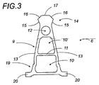
示された好ましい実施形態に関してレール6はその断面の全体形状がほぼ三角形のタイプの本体9を呈する。
With respect to the preferred embodiment shown, the
横方向応力に対する満足すべき強度が確保されて材料も節約されるためには、レール6の本体9は中空の小箱構造を呈すると同時に、このように、例えば、仕切壁11により分離されかつ円筒穴12が上に載るほぼ台形断面の2つの重ねられた小箱10を含む。
In order to ensure a sufficient strength against lateral stresses and to save material, the
本発明に欠かせない特徴によると、レール6はその横方向仕切壁13の少なくとも1面にその重量がかかるが、これらのそれぞれにかかる方が好ましく、スチールで製作されるのが好ましい導体路8によりゼロボルト帰路が可能となる。導体路8は様々な図面で示されるように対称であると同時にほぼ鉛直であることが好ましい。
According to the essential features of the present invention, the
レール本体9はきのこ部とも呼ばれ得る充足断面のレール頭部14が上部の方に続く。
The
示された例では、この頭部は、傾斜すると同時に、例えば、軽く膨らんだ盤面17により上部部分に結合される両側の走行路16を伴う傾斜すると同時に上部の方に拡がる下部横腹部15が両側にある台形状の全体形状の断面を呈する。
In the example shown, the head is tilted at the same time as, for example, the
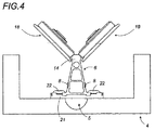
こうして、これは、図4および図9に示されるように、対応するレール6の頭部14の2本の傾斜路16上を走行するようになる傾斜したV字状の2個の誘導ローラー18が含まれ得る車両あるいは通電腕金の誘導全体装置向けの誘導レールとして利用され得る。
Thus, as shown in FIGS. 4 and 9, this is two inclined V-shaped
下部付近では、レール6の本体9はその両側面を越えて溝の底部でその固定を可能にする長手方向支持縁20まで拡幅される基盤部19で終わるのが好ましい。
Near the lower part, the
レール6は例えば0.8メートル毎の一定間隔でかつ、例えば枕木にねじ留めされるクラマージュといわれる挟み部品22を介在して配置される溝4の底部の枕木21に固定される。
The
これらの枕木21のそれぞれの横方向端部23の面に横腹断面25の下端24が挟み留めにより固定される。
The
2つの横腹断面25により横方向に電流供給装置が区切られる。これらの外側面はコンクリート中に包まれる。これらの横腹断面25は、例えば、極めて小さな負荷で引き抜き成形されるプラスチック材料で製作可能である。
The current supply device is divided in the lateral direction by the two
既に言及されたように、本発明による電流供給装置2には、レール6の両側にかつこれからある距離だけ離れて溝4内に設置される少なくとも1本の、しかし好ましくは2本の直線導体路7が含まれる。
As already mentioned, the
これらの導体7はほぼ台形の対称形断面を呈するのが好ましいと同時に、例えば、ステンレススチール、アルミニウム、あるいは銅といったような適切なすべての導体材料から製作可能である。
These
これらが極めて低い電圧(プラス60ボルトあるいはマイナス60ボルト)に接続される場合には、導体7は大きなアンペアの電流を受ける。これらは、従って、比較的大きな表面の断面を呈さなくてはならない。重量と値段の理由で、アルミニウムの採用がこれらの導体の製作に最適であろう。
When they are connected to a very low voltage (plus 60 volts or minus 60 volts), the
電流通電装置3の集電靴と直線導体7間の摩擦の良好な条件が確保されるためには、これらの導体の対応面が、例えば、およそ1ミリの厚さのステンレス製薄板の摩擦板26で被覆されるのが好ましい。示された好ましい例では、この摩擦板26は各導体7の下部平面27の面上に付加される。
In order to ensure good conditions for friction between the current collector shoe of the current-carrying
図8に示されるように、直線導体7は必ずしも単一の塊ではない。
As shown in FIG. 8, the
より小さな断面積で十分である場合には直線導体7は、例えば、ほぼ台形断面の絶縁支持材56中に埋め込まれる直線導体心線55から形成され得る。
If a smaller cross-sectional area is sufficient, the
絶縁支持材56には下部部分に直線心線導体55が強制気味に取付けられると同時に保持される受入れ溝57が含まれる。直線導体心線55の下部平面58の面は自由のままであると同時に絶縁支持材56の内部に軽く引っ込んでいるのが好ましい。
The insulating
供給直線導体7は懸垂される一連の吊り金物28により支持される。
The supply
各吊り金物28には、対応する導体7あるいは絶縁支持材56の上部部分の形状に合う2枚の横方向仕切壁30を通ってこれらの横方向縁の領域で下方に伸びる上部仕切壁29が含まれるのが好ましい。
Each
これらの吊り金物28の少なくとも1枚ならびに好ましくはそのそれぞれは、導体7の両側に配置されるとともに、これらの上部仕切壁29の領域で結合されると同時に、導体7あるいはこの絶縁支持材56が挟み留めにより固定されるように締付けにより組立てられるくさび形状の2つの部品31から形成され得る。
At least one of these
吊り金物にはその機能が後で明らかにされる上方に突き出た上部先端突起部32も含まれるのが好ましい。
Preferably, the hanger also includes an
吊り金物28は間隔をおいて設置される。これらは、例えば、およそ800ミリメートルで等間隔に配置されるが、特にカーブ部分では、さらに短い等間隔で配置可能である。
The hanging
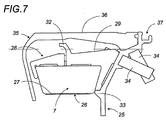
図7および図8に見られるように、吊り金物28は横腹断面25の支持リブ33上に乗ると同時に、例えば、そのナットがコンクリート中に取り込まれるネジ釘34によってこの上に固定される。
As can be seen in FIGS. 7 and 8, the
保護断面35が少なくとも1つの好ましくはそれぞれの横腹断面25に固定される。この固定は、また、そのナットがコンクリート中に取り込まれるネジ釘34によって固定される保護断面35の端部が中で噛合するようになる各横腹断面25の上端面で行われるのが好ましい。
A
保護断面35は傾斜したL字の全体形状を呈すると同時に下部に置かれる直線導体7を取り囲むのが好ましい。
The
この存在により、こうして安全が完全に確保される電圧下の直線導体7への利用者の万一の接近が禁じられる。これにより、さらに、物体、工具、破片あるいはその他の本発明による電流供給装置内への望ましくない、偶然のあるいは悪意的なあらゆる侵入が遮断される。これにより悪天候に対する装置の保護もまた確保される。
Due to this presence, the user should be prevented from approaching the
上記で説明された全体装置の建設は各導体7がこれへの接近を不可能にする全体的にL字形状の保護断面35により隠されるように施工される。この特徴により、必要に応じて低電圧の利用と組み合わされる本発明による電気供給装置は完全に公共上安全な装置となる。
The construction of the overall device described above is carried out in such a way that each
保護断面35は、排水溝が形成される対応した河岸の方に向かう雨水の流れに関して軽く外側の方に傾斜した上部区域36を呈するのが好ましい。各側の横腹断面25の長手方向端部溝部37に取付けられる図には示されていない中間継手により防水分離が確保される。
The
都合の良いことに、レール6と保護断面35間には溝4の底部の向かう雨水ならびに例えば破片あるいは小物体といった異物の排出を可能にする空間がある。
Conveniently, there is a space between the
あらゆるひっかかりが回避されるよう、枕木21の無い、レール6の基盤部19と横腹断面25の下端24の間に存在する空間は、レール6と保護断面35の間に存在する空間よりも大きな寸法である。保護断面35は交差部で別の電動車両の重量を支えるため、あるいは交差部面での通常の車両、歩行者、自転車利用者、バイク利用者の通行ならびに従来の交通軌道とともに整備される面の通行を可能にするために十分な強度がなくてはならない。
In order to avoid any catches, the space between the base 19 of the
これらの断面は軽い可撓性があり、ある一定のあるいはそれぞれの導体支持吊り金物28から突き出た上部先端突起部32が、図7に見られるように、支持止め具として形成されこれにより変形が大きな場合の応力の反復が可能となる。
These cross sections are light and flexible, and an
上記で説明された構造は連続的である。吊り金物28に関しては局所的であり得る、つまりは間隔をおいて繰り返される部品の形であり得る。横腹断面25は連続的であるがコンクリートに埋め込まれるとともに等間隔で設置されるインサートにより固定される。
The structure described above is continuous. The
次に車両に搭載されると同時に図9から図11に例示される電流通電装置の説明のさらに詳細に入ろう。 Next, a description will be given in more detail of the explanation of the current supply device illustrated in FIGS.
車両の利用回路の機能に必要な電気エネルギーの回収は、少なくとも1つの好ましくはレール6の両側の溝4内を走る、例えば対称な2つの移動通電構成部品38によって行われる。
The recovery of the electrical energy required for the function of the vehicle utilization circuit is effected by at least one preferably two moving
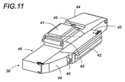
各通電構成部品38の主要部分は図11および図12の透視図に示された通電靴39である。2つの通電靴39は好ましくは同一であって、片方が他方に対して逆転されるだけで単純に配置される。
The main part of each energizing
示された好ましい変型例について、各靴39は細長い本体40を呈すると同時に、これには中央位置に好ましくは対応する供給導体7の摩擦板26で被覆される構成面27あるいは58と滑り接触状態になるほぼ水平な出力集電靴41が含まれる。
For the preferred variant shown, each
勿論、この出力集電靴41はどのような場合でも電気的な導体接触が確保されるように導体7と弾性復元力接触状態に取付けられ得る。
Of course, this output current collecting
都合の良いことに、稼働中は、出力集電靴41と供給導体7の間の接触は傾斜したL字形状の保護断面35の下で生じると同時に、この保護断面の折り返しにより取り囲まれる。
Conveniently, during operation, contact between the output
各通電靴39には、レール6側に向けられるその横腹上に、レール6により支えられる対応するゼロボルト導体帰路8上で電気的な滑り接触状態であると同時にこれが維持されるように配されるゼロボルト帰路集電靴42も含まれる。これらの集電靴42は対応する帰路8と弾性復元接触状態で取付けられることも可能である。
Each energizing
出力集電靴41およびゼロボルト集電靴42は電気的な導体材料で製作される。電気的に絶縁材料で製作される通電靴39の本体40により2つの集電靴間の絶縁が確保可能となる。
The output
都合の良いことに、通電靴39の本体40は、例えば、各集電靴とそのばねを取り囲む小箱から形成される緩衝器43と一体にすることも可能である。
Conveniently, the
出力41ならびにゼロボルト帰路42の各集電靴は車両との電気連結のために供給導体域に電気的に接続される。
Each collector shoe of
電気接触の迅速接続装置と一体となった保護蓋44により各集電靴が所定位置に都合良く固定され得る。また、メンテナンスが容易となるよう、集電靴ならびにこれらの電気的接続は、特にこれらの交換のために蓋44との一体性を維持する1本だけのネジ釘45のネジが戻されて解除され得るのが好ましい。
Each collecting shoe can be conveniently fixed in place by a
2つの通電靴39は動的安定性のために車両の誘導腕金に取付けられるのが好ましい支持架線装置46により支持されると同時に機械的に結合される。
The two current-carrying
図9に図示された支持架線装置46には逆U字の全体形状の2本の腕金支持材47が含まれると同時に、腕金の方に向いて位置する好ましくは外側の方に曲げられたその自由端48により通電靴39の固定を可能にする連結板49が形成される。
The support
U字の2本の支持腕金47により支持架線装置46の前後部分が形成される。これらは各横腹上にU字の2本の支持腕金47の対応する横方向分岐を接合する好ましくはほぼ水平の2本の補強横棒50により結合される。
The front and rear portions of the support
支持架線装置46により2つの機能が満たされる。
Two functions are satisfied by the support
一方で、溝内部で通電構成部品38が支持されると同時に、他方でこれらの通電構成部品38と車両の利用者回路間の電気的連結が確保される。
On the one hand, the current-carrying
この後者の機能は支持腕金47を形成すると同時に桟の電気的絶縁を確保する複合材料の導体芯材に埋め込まれる銅桟51によって行われるのが好ましい。
This latter function is preferably performed by a
各通電靴39は異なる支持腕金47にそれぞれ付属する連結板49によって支持架線装置46上の前後に固定される。
Each energizing
これらの連結板49の1枚は出力集電靴41に電気的に接続されると同時に、これにより、例えば対応する支持腕金47の横方向分岐の介在により車両の利用者回路までの出力電流の伝導が可能となる。もう1枚の板49はゼロボルトへの集電靴42に電気的に接続されると同時に、これにより、例えば、対応する支持腕金47の横方向分岐を経由してゼロボルト帰路が生ずるのが可能となる。
One of these connecting
車両の正常な機能の枠内では、本発明による床付け電気供給装置は通電構成部品38が本線の最初の通電位置にある溝4内に挿入されると同時に本線の最後でしか再び出ることがないように設置される。
Within the framework of the normal functioning of the vehicle, the floor-mounted electricity supply device according to the invention can only reappear at the end of the main line at the same time that the current-carrying
しかしながら、本発明の安全性と迅速性の理由のために、本発明による装置により通電構成部品38からの切り離し、ならびに、例えば、故障、事故あるいは何らかの問題の場合に支持架線装置46の通電中の切り離しが可能となる。
However, for reasons of safety and speed of the present invention, the device according to the present invention may be disconnected from the energized
有利なことに、人の安全性にかかわる重大な故障の場合にこの通電中の分離が溝内に存在するその他の要素を害することなく行われ得る。さらには、これにより溝から外部の要素に電圧がかからないことが確保される。 Advantageously, in the case of a serious safety-related failure, this energization separation can be performed without harming other elements present in the groove. Furthermore, this ensures that no voltage is applied to the external elements from the groove.
このため、また、図9に示されるように、支持架線装置46はその補強横棒50に関して長手方向の接続の分離が可能である。こうしてこれは上部の境界部品52ならびに少なくとも1つの好ましくは2つの下部接続部品53に分割可能である。上部境界部品52はその横腹のそれぞれの上でそれぞれ2枚の連結板49で終わる下部接続部品53により延長されるのが好ましい。
For this reason, as shown in FIG. 9, the support
2つの接続部品53は同一であると同時にU字の全体形状をとるのが好ましい。これらは止めピンあるいは予め決められた限界より大きな圧力下で降伏する剪断ネジ釘54によって上部境界部品52との一体化が可能である。
The two connecting
明らかなように、本発明はこれまでに説明されると同時に様々な図面で示された好ましい実施形態に限定されることはなく、専門家により多くの変更例がもたらされると同時に本発明の範囲と枠組から逸脱することなく別の変型例が考案されることがあり得る。 As will be apparent, the invention is not limited to the preferred embodiments described above and shown in the various drawings, and many modifications are made by a specialist while at the same time the scope of the invention. Other variations may be devised without departing from the framework.
本発明の有利なその他の特徴は以下に続く詳細説明、付録の図が参照されてなされる説明が読まれれば明らかになろう。すなわち、 Other advantageous features of the invention will become apparent upon reading the following detailed description and the description made with reference to the accompanying figures. That is,
Claims (36)
これらの2本の導体(7)が2本のゼロボルト導体帰路(8)を支えると同時にさらに傾斜したL字の全体形状を呈する2つの保護断面(35)が含まれる中央レール(6)の両側の溝(4)に設置され、これらの保護断面(35)のそれぞれにより下部に設置される直線導体(7)の1本が取り囲まれると同時に隠されるようになること、通電搭載装置(3)に中央レール(6)の両側の溝(4)内を走る全体支持架線装置(46)により担われる2つの移動通電構成部品(38)が含まれ、これらの各通電構成部品(38)に、対応する供給導体(7)と電気的にすべり接触状態になるよう仕向けられる出力集電靴(41)ならびに対応するゼロボルト導体帰路(8)と電気的にすべり接触状態になるよう仕向けられるゼロボルト集電靴(42)が含まれ、これらの出力(41)ならびにゼロボルト(42)の集電靴が車両の利用者回路に電気的に接続されること、ならびに各出力集電靴(41)と対応する供給導体(7)間の接触が対応する保護断面(35)の下で行われるとともにこの保護断面の折り返しにより取り囲まれることを特徴とする請求項1あるいは請求項2による給電装置 The current supply device (2) includes two linear supply conductors (7) each connected to a supply voltage,
Both sides of the central rail (6) including these two conductors (7) support two zero-volt conductor return paths (8) and at the same time include two protective cross-sections (35) exhibiting a further inclined L-shape. One of the straight conductors (7) installed in the lower part of each of the protective cross sections (35) is surrounded and simultaneously hidden by each of these protective cross sections (35); Includes two moving energized components (38) carried by the overall support overhead line device (46) running in the grooves (4) on both sides of the central rail (6). Each of these energized components (38) An output current collector shoe (41) that is intended to be in electrical sliding contact with the corresponding supply conductor (7) and a zero volt current collector that is intended to be in electrical sliding contact with the corresponding zero volt conductor return path (8). shoes 42) and these outputs (41) as well as zero volt (42) current collector shoes are electrically connected to the vehicle user circuit, and each output current collector shoe (41) and corresponding supply conductor 3. The power supply device according to claim 1, wherein the contact between (7) takes place under the corresponding protective cross section (35) and is surrounded by the folding of the protective cross section.
Applications Claiming Priority (3)
| Application Number | Priority Date | Filing Date | Title |
|---|---|---|---|
| FR0410356 | 2004-09-30 | ||
| FR0410356A FR2875751A1 (en) | 2004-09-30 | 2004-09-30 | ELECTRIC GROUND POWER SYSTEM FOR ELECTRIC VEHICLE |
| PCT/FR2005/002338 WO2006035139A1 (en) | 2004-09-30 | 2005-09-21 | Ground power supply system for electric vehicle |
Publications (2)
| Publication Number | Publication Date |
|---|---|
| JP2008514500A true JP2008514500A (en) | 2008-05-08 |
| JP4824690B2 JP4824690B2 (en) | 2011-11-30 |
Family
ID=34951686
Family Applications (1)
| Application Number | Title | Priority Date | Filing Date |
|---|---|---|---|
| JP2007534043A Expired - Fee Related JP4824690B2 (en) | 2004-09-30 | 2005-09-21 | "Electric vehicle power supply device via floor" |
Country Status (8)
| Country | Link |
|---|---|
| US (1) | US7748509B2 (en) |
| EP (1) | EP1802485A1 (en) |
| JP (1) | JP4824690B2 (en) |
| KR (1) | KR101166279B1 (en) |
| CN (1) | CN101044040B (en) |
| FR (1) | FR2875751A1 (en) |
| RU (1) | RU2374095C2 (en) |
| WO (1) | WO2006035139A1 (en) |
Cited By (1)
| Publication number | Priority date | Publication date | Assignee | Title |
|---|---|---|---|---|
| JP2010513760A (en) * | 2006-12-22 | 2010-04-30 | ロール インダストリー | Anti-escape safety device for guidance unit with two inclined rollers rotating on rail |
Families Citing this family (15)
| Publication number | Priority date | Publication date | Assignee | Title |
|---|---|---|---|---|
| FR2921021B1 (en) * | 2007-09-13 | 2014-07-04 | Lohr Ind | REPETITIVE LATERAL TRANSVERSAL ARRANGEMENT FOR ELECTRICAL SIDE POWER PROFILE OF A MOTORIZED ELECTRIC MOTORIZED VEHICLE. |
| FR2938800B1 (en) * | 2008-11-21 | 2010-12-24 | Alstom Transport Sa | SUPPORTING SUPPORT SUPPORT SUPPORT |
| KR101130687B1 (en) * | 2009-04-15 | 2012-04-02 | 오성기전주식회사 | Power rail assembly for railroad car |
| MY166734A (en) * | 2009-04-15 | 2018-07-19 | Posco Ict Co Ltd | Conductive rail facility for railway vehicles and fitting thereof |
| SE1000327A1 (en) * | 2010-04-01 | 2011-08-23 | Elways Ab | A rail construction adapted for one or more electrically propulsive vehicles |
| GB2485616A (en) * | 2010-11-22 | 2012-05-23 | Bombardier Transp Gmbh | Route for transferring electric energy to vehicles |
| JP4898963B1 (en) * | 2011-02-28 | 2012-03-21 | 三菱重工業株式会社 | Guide rails and traffic systems for track vehicles |
| CN102951041B (en) * | 2011-08-22 | 2015-09-09 | 陈海水 | The anti-disconnect type double protection method that knocks into the back of electric train |
| KR102331404B1 (en) * | 2013-09-21 | 2021-11-25 | 마그네모션, 인코포레이티드 | Linear motor transport for packaging and other uses |
| CN204039861U (en) * | 2014-07-29 | 2014-12-24 | 李嘉发 | A kind of road for electric vehicle charging |
| US10490687B2 (en) | 2018-01-29 | 2019-11-26 | Waymo Llc | Controlling detection time in photodetectors |
| CN110789406B (en) * | 2018-08-01 | 2022-08-09 | 比亚迪股份有限公司 | Charging rail and rail transit system with same |
| CN112572238B (en) * | 2021-01-15 | 2023-05-26 | 安徽华信电动科技股份有限公司 | Anti-breaking device for plastic bags of trolley wire rail |
| CN113306404B (en) * | 2021-04-29 | 2022-10-25 | 中车青岛四方机车车辆股份有限公司 | Rail vehicle ground power supply interlocking device and rail vehicle ground power supply access method |
| FR3128415A1 (en) * | 2021-10-18 | 2023-04-28 | Philippe Nobileau | Safe "low voltage" conductive connection device to the ground for static and dynamic load. |
Family Cites Families (24)
| Publication number | Priority date | Publication date | Assignee | Title |
|---|---|---|---|---|
| DE175461C (en) * | ||||
| US502842A (en) * | 1893-08-08 | Robert r | ||
| US562796A (en) * | 1896-06-30 | brandenburg | ||
| US483761A (en) * | 1892-10-04 | Closed conduit for electric railways | ||
| US413294A (en) * | 1889-10-22 | Conduit for electric railways | ||
| US452160A (en) * | 1891-05-12 | Electric railway | ||
| US454023A (en) * | 1891-06-16 | Electric railway | ||
| US323675A (en) * | 1885-08-04 | henderson | ||
| US519328A (en) * | 1894-05-08 | And william p | ||
| US492737A (en) * | 1893-02-28 | Conduit electric railway | ||
| US463197A (en) * | 1891-11-17 | Electrical conduit | ||
| DE106673C (en) * | ||||
| DE176461C (en) * | 1905-09-08 | |||
| US1010504A (en) * | 1911-03-20 | 1911-12-05 | Frederick Hale Lindsley | Third-rail covering. |
| US1763495A (en) * | 1929-01-21 | 1930-06-10 | William B Young | Adjustable mounting for electric bulbs |
| US3848712A (en) * | 1973-04-09 | 1974-11-19 | B Flodell | Device for supplying an object propelled along a rail or the like with electrical current |
| CH598971A5 (en) * | 1975-01-21 | 1978-05-12 | Josef Beck | Conductor rail for battery car |
| US4083439A (en) * | 1975-09-16 | 1978-04-11 | Chandler Leo E | Power collection device for electric powered rail cars |
| US4129203A (en) * | 1977-06-13 | 1978-12-12 | Nelson Berman | Roadway vehicle |
| FR2735728B1 (en) * | 1995-06-23 | 1997-08-08 | Lohr Ind | POWER SUPPLY AND GUIDANCE ASSEMBLY ALONG A GROUND RAIL FOR VEHICLE ON WHEELS |
| CN1184044A (en) * | 1996-12-04 | 1998-06-10 | 张声凯 | Power supply system grounding method and device for trolleybus |
| FR2800020B1 (en) * | 1999-10-25 | 2003-10-03 | Alstom | STATIC GROUND SUPPLY SYSTEM FOR ELECTRIC VEHICLE AND ELECTRIC VEHICLE FOR SUPPLY USING SUCH A SUPPLY SYSTEM |
| DE10160247A1 (en) | 2001-05-25 | 2003-06-18 | Sobolewski Walter | Combi vehicle for use on railways |
| CN1463868A (en) * | 2002-06-14 | 2003-12-31 | 李善伯 | Electric automobile floor groove power transmission operating state information acquisition method |
-
2004
- 2004-09-30 FR FR0410356A patent/FR2875751A1/en not_active Withdrawn
-
2005
- 2005-09-21 RU RU2007115611/11A patent/RU2374095C2/en not_active IP Right Cessation
- 2005-09-21 JP JP2007534043A patent/JP4824690B2/en not_active Expired - Fee Related
- 2005-09-21 US US11/664,173 patent/US7748509B2/en not_active Expired - Fee Related
- 2005-09-21 EP EP05805761A patent/EP1802485A1/en not_active Withdrawn
- 2005-09-21 KR KR1020077006851A patent/KR101166279B1/en not_active IP Right Cessation
- 2005-09-21 CN CN2005800331516A patent/CN101044040B/en not_active Expired - Fee Related
- 2005-09-21 WO PCT/FR2005/002338 patent/WO2006035139A1/en active Application Filing
Cited By (1)
| Publication number | Priority date | Publication date | Assignee | Title |
|---|---|---|---|---|
| JP2010513760A (en) * | 2006-12-22 | 2010-04-30 | ロール インダストリー | Anti-escape safety device for guidance unit with two inclined rollers rotating on rail |
Also Published As
| Publication number | Publication date |
|---|---|
| US7748509B2 (en) | 2010-07-06 |
| EP1802485A1 (en) | 2007-07-04 |
| KR101166279B1 (en) | 2012-07-17 |
| CN101044040A (en) | 2007-09-26 |
| US20080105509A1 (en) | 2008-05-08 |
| KR20070067106A (en) | 2007-06-27 |
| RU2007115611A (en) | 2008-11-10 |
| CN101044040B (en) | 2012-05-23 |
| FR2875751A1 (en) | 2006-03-31 |
| RU2374095C2 (en) | 2009-11-27 |
| JP4824690B2 (en) | 2011-11-30 |
| WO2006035139A1 (en) | 2006-04-06 |
Similar Documents
| Publication | Publication Date | Title |
|---|---|---|
| JP4824690B2 (en) | "Electric vehicle power supply device via floor" | |
| US20210114474A1 (en) | Contact apparatus and charging contact unit and method for electrically connecting a vehicle to a charging station | |
| KR101231058B1 (en) | Bridge having track for hybrid transport system | |
| CA2781993C (en) | Positioning and/or holding a plurality of line sections of electric lines along a drive way of a vehicle | |
| CN104943565A (en) | Ground level power supply system for a non-guided vehicle | |
| JP2009511320A (en) | Section insulator for rigid train lines | |
| US20160075258A1 (en) | Gantry type movable catenary system at a railway crossing | |
| JP2019515842A (en) | Power supply structure for orbital traffic | |
| KR101237476B1 (en) | High security device for capturing electric energy on the ground for supplying a landborne vehicle | |
| US9845025B2 (en) | Rigid T-rail conductor system | |
| KR101106038B1 (en) | Conductor rail line of rubber wheel automated guidway transit type light weight railway | |
| CN105480119A (en) | Independent return current rail technique of DC traction electricity supply system for railway traffic | |
| CA2366111C (en) | Power rail and guidebeam assembly for a vehicle transportation system | |
| KR100869761B1 (en) | Power supply apparatus for light electric railway | |
| KR20100134831A (en) | A safety system for the high voltage trolley wire | |
| US5117072A (en) | Constant current non-bridging section insulator | |
| KR20220119641A (en) | Track section for driving electric railway vehicles | |
| KR102599071B1 (en) | rigid bar transition device for high speed electric railroad | |
| KR102602939B1 (en) | Rigid conductor and rigid conductor overlap | |
| KR200463734Y1 (en) | Earthing Device for Automatic Guided Transit | |
| US11059496B2 (en) | Ground-based power supply and associated reinforcing method | |
| KR20230152507A (en) | Installing Method Of Expansion Joint For Overhead Rigid Catenary | |
| Pande et al. | Light Weight Rigid OCS in Elevated Section of Delhi MRTS | |
| NL1036575C2 (en) | SOLAR SYSTEM THAT PRODUCES ELECTRICITY ABOVE RAIL LINES. | |
| JPH07163006A (en) | Electrifying system of nonelectrified railroad having small-height and narrow section in railroad track |
Legal Events
| Date | Code | Title | Description |
|---|---|---|---|
| A621 | Written request for application examination |
Free format text: JAPANESE INTERMEDIATE CODE: A621 Effective date: 20080919 |
|
| A131 | Notification of reasons for refusal |
Free format text: JAPANESE INTERMEDIATE CODE: A131 Effective date: 20110329 |
|
| A601 | Written request for extension of time |
Free format text: JAPANESE INTERMEDIATE CODE: A601 Effective date: 20110629 |
|
| A602 | Written permission of extension of time |
Free format text: JAPANESE INTERMEDIATE CODE: A602 Effective date: 20110706 |
|
| A521 | Written amendment |
Free format text: JAPANESE INTERMEDIATE CODE: A523 Effective date: 20110728 |
|
| TRDD | Decision of grant or rejection written | ||
| A01 | Written decision to grant a patent or to grant a registration (utility model) |
Free format text: JAPANESE INTERMEDIATE CODE: A01 Effective date: 20110830 |
|
| A01 | Written decision to grant a patent or to grant a registration (utility model) |
Free format text: JAPANESE INTERMEDIATE CODE: A01 |
|
| A61 | First payment of annual fees (during grant procedure) |
Free format text: JAPANESE INTERMEDIATE CODE: A61 Effective date: 20110908 |
|
| R150 | Certificate of patent or registration of utility model |
Free format text: JAPANESE INTERMEDIATE CODE: R150 |
|
| FPAY | Renewal fee payment (event date is renewal date of database) |
Free format text: PAYMENT UNTIL: 20140916 Year of fee payment: 3 |
|
| LAPS | Cancellation because of no payment of annual fees |